on the flight paths and lifetimes of burning particles of...
TRANSCRIPT

Tenth Symposium (International) on Combustion, pp. 1021-1037, The Combustion Institute, 1965
ON THE FLIGHT PATHS AND LIFETIMES OF BURNING PARTICLES OF WOOD
C. SANCHEZ TARIFA, P. PEREZ DEL NOTARIO, AND F. GARClA MORENO
Institute Nacional de Tecnica Aeroespacial "Esteban Terradas", Madrid, Spain
Results of a research program on the burning properties, flight paths and lifetimes of burning particles of wood are given in the paper. This study is related to fire spread produced by fire brands, which is the dominating propagation mechanism in major forest fires.
The laws of variation of the aerodynamic drag and weight of firebrands as functions of both time and relative wind speed are obtained experimentally in a wind tunnel. From these data the flight paths and corresponding lifetimes of the firebrands are calculated for giving horizontal wind conditions and for a certain model of the convection column above a fire.
The conclusion was drawn that it is an excellent approximation to assume that the firebrands always fly at their final or terminal velocity of fall. This assumption considerably reduces the experimental work as well as the theoretical studies.
The results obtained permit the valuation of the dangerous areas of possible fire propagation. Comparative results of the potential danger of firebrands according to size, shape, kind of wood, moisture content, and wind conditions are shown.
A preliminary study of the general laws governing combustion of wood with forced convection is also included.
1. Introduction
In high-intensity forest fires the dominating fire propagation mechanism is the transport of burning embers or firebrands ahead of the fire front. Burning pieces of wood are carried aloft by the convective air currents, and then they are carried forward by the winds.
Showers of thousands of burning embers ignite large areas ahead of the fire. This phenomenon, called spotting, is one of the worst characteristics of major fires, increasing their intensity and making fire suppression much more difficult.1
In extremely adverse conditions some firebrands can be carried up to very high altitudes, and then they may ignite secondary fires several kilometers from the main fire front. These secondary fires are very dangerous and they are very difficult to prevent and suppress.
The present work is a contribution to the study of the burning characteristics and flight paths of firebrands. Particles of several kinds and shapes of wood were burned in wind tunnels; the variations of their weight and aerodynamic drag were recorded as functions of time. From these data can be calculated the flight paths and burning-out times of the firebrands under given wind conditions, as well as the maximum dis
tance that may be reached by the firebrands still burning.
These results permit the evaluation of the dangerous areas of possible fire propagation and give comparative results of the potential danger of firebrands according to size, shape, kind of wood, and moisture content.
These works are part of a research program2,3
carried out at the Instituto Nacional de Tecnica Aeroespacial, Madrid. This research program is being sponsored by the Forest Service of the United States Department of Agriculture, under a five year Grant.
2. Fundamental Equations
The motion of firebrands was studied by assuming that they behave as a point mass, and the aerodynamic drag assumed to act in the opposite direction to the motion of the center of gravity of the firebrand.
On these assumptions, the two-dimensional motion of a firebrand of mass m moving at the absolute velocity Y(x, y, t) within a wind u(x, y, t) is governed by the following system of differential equations:
dVx dux dwx , n . „wx . . m — - = m-7T — m - — = —fpColw2 — (1)
dt dt dt w
1021

1022 AERODYNAMICS I N COMBUSTION
dVy dt
dUy
~dl dwv i n A 2W*
— — ^PCDAW* mg.
w dt
(2)
In these equations vr(x, y, t) is the relative velocity of the wind with respect to the firebrand, CD is the aerodynamic drag coefficient, p is the air density, and A is the maximum cross section area of the firebrand.
Considering constant wind conditions, we find
dwx/dt + i(pCDA/m)wwx = 0
dwy/dt + %(pCr>A/m)wwy — g 0.
(3)
(4)
Since the particle is burning, its mass, cross section area, and drag coefficient are functions of both time and relative wind speed.
Therefore, parameter
a = pCT,A/2m (5)
is a function of w and t. The problem lies in the integration of System
(3)-(4), in order to obtain the flight paths of the firebrands by means of the expressions
X = I (ux — wx) dt,
Y — / (uv ~ wv) dt.
(6)
(7)
Function a(w, t) has to be determined experimentally. Burning-out time ti(w, t) is also
experimentally obtained. This burning-out time may be longer or shorter than the time tg required for a firebrand to reach the ground.
In the first case, the firebrand reaches the ground while still burning, and in the second case, the firebrand burns out in the air. When k = tg, the maximum horizontal range of possible fire propagation is reached.
3. Research Facilities
In order to determine functions a(w, t) and tb(w, t), the experimental procedure was selected that consists of burning particles of wood in a wind tunnel; the weight and the aerodynamic drag of the firebrand were recorded as functions of time.
Two wind tunnels were designed and constructed to carry out the research program. One of the tunnels (Fig. 1) is a suction-intake wind tunnel in which the air speed is controlled by means of lateral-air intakes and with a throttle valve. In this way wind speed can be varied from 0 to 40 m/sec. The particles of wood were suspended with a thin steel wire at the test section. The particle was ignited with the flame of a butane torch and the weight and the aerodynamic drag recorded as functions of time by means of a two-component strain-gauge balance and with a four channel pen-recorder Micrograph. The variation of the size of the firebrand was recorded by taking photographs during the combustion process.
Arm Supported by o Two-Components Strain Gauge Balance
w/////////////////"////////^^^^ FIG. 1. Diagram of the horizontal wind tunnel. Another similar wind tunnel, but vertical, was also
utilized.

FIREBRANDS 1023
Tests were carried out at constant or at variable wind speed.
The second tunnel is similar to the one described, but it is placed in a vertical position with the intake section down. This wind tunnel was placed in this way in order to facilitate the tests in which the wind speed is to be kept continuously equal to the terminal velocity of fall of the firebrand.
Wind speed was continuously reduced as the firebrand burned, in order to keep the steel wire (which holds the firebrand) in a horizontal position. In this way, the aerodynamic drag of the firebrand was kept equal to its weight throughout the combustion process.
Similar tests at the terminal velocity of fall can be performed in the horizontal wind tunnel, equalizing the recorded values of the weight and
the aerodynamic drag of the firebrand by reducing continuously the wind speed.
4. Experimental Results
The research program comprised the study of different types of firebrands. Their size, shape, kind of wood, and moisture content were the parameters of the process investigated.
Spherical and cylindrical firebrands of different size, and of five kinds of wood, have been studied so far.
The initial diameters of the spheres were between 10 and 50 mm. The cylinders ranged from 6 to 15 mm in diameter and from 18 to 36 mm in length. Firebrands of pine wood (pinus pinaster), oak (quercus rubra), aspen (populus tremuloides), spruce (picea excelsa) and balsa
1200
1100<
1000
•700
.0)600 O)
500
400
300
200
100
Wind tunnel air speed
I n i t i a l weight mgr
Lifetime Wind tunnel air speed
I n i t i a l weight mgr
Lifetime
0 1 m/sec. 1,100 5m 37s
O 4m/sec . 1,100 3m 41s
X 7 m / s e c 1,100 2 m 4 3 s
Pinus pir D0 =15 MC=201
aster wood mm.
— ' •»*—J o ^^w="——»
t
Time, min.
FIG. 2. Weight of firebrands as a function of time. Each curve represents the average values of four or five experiments.

1024 AERODYNAMICS IN COMBUSTION
(ochroma lagopus) have been studied, with moisture contents ranging from 2% to 25%.
The firebrands were burned in the wind tunnels at constant or variable wind speed. Spheres and cylinders kept their shape, more or less, as they burned. Since wood is not a homogeneous substance, results showed considerable dispersion which made necessary the utilization of average values (see Figs. 5 and 6).
The cylindrical firebrands were held with their axis perpendicular to the direction of the wind during the tests. This is the position of maximum drag and it is also the position of maximum stability in a free fall. However, a study was made of the possible influence of the free motion of the cylinder on its burning characteristics and on its aerodynamic drag, and it was concluded, that the procedure that consists of keeping the cylinders at rest did not introduce any significant error in the study of the flight- and burning-characteristics of firebrands. [This study was made by measuring the free fall times of cylinders dropped from a balloon at heights of 100 and 200 meters and by comparing these times
with those calculated by assuming that the cylinders fall in the position of maximum drag. The influence of the motion of the cylinders on their burning-out times was also studied.]
Some experimental results obtained at constant wind speed are included in Figs. 2 and 3. They show typical laws of variation of weight, mean diameter, and aerodynamic drag as functions of time.
When the air speed is low, the firebrands flame at the initial state of the burning process and glow from then onwards. At high speed there was no flaming and all combustion occurred as a glowing process.
The weight of the firebrand changed rapidly at first, and then decreased slowly. Diameters decreased according to a quadratic law (see Sec. 8).
5. Solution of the System
System (3)-(4) of differential equations is of difficult analytical solution, because a is a complicated function of w and t. Fortunately,
-.400
300
200 E
100
J 0
PIG. 3. Diameter and aerodynamic drag of a firebrand as functions of time.

FIREBRANDS 1025
made by taking a constant value of a, it was promptly verified that velocities wx and wy tend very rapidly toward their asymptotic values.
In Fig. 4 two representative cases are shown. It may be seen that in 2 or 3 sec wx and wy are very close to their asymptotic values. On the other hand, burning-out time of those firebrands is of the order of 2-3 min. Therefore, in order to calculate the flight paths it is an excellent approximation to assume that the firebrands always fly at their terminal velocity of fall.
System (3)-(4) can be integrated analytically by taking a constant value of parameter a
QK. 1 1 1 1 1 1 1 1 1 1 1 1 1 1 1 0 .2 .4 .6 .8 1.0 1.2 U 1JS 1jB 2P 2.2 2.4 2.6 2.8 3.0
if sec
WXo = 20 m/sec. PINUS PINASTER SPHERE Wy0 = 20 m/sec.
VVy0 * 0 D0 =17 mm. MC.= 20%
FIG. 4. Components wx and wy of the relative wind velocity tend rapidly toward zero, and toward the final velocity of fall wf, respectively.
there exists an approximated solution which gives excellent results for the calculation of the flight paths.
Solution of System (3)-(4) gives the asymptotic values:
Mt^az = wxf = 0 (8)
(%)**» = Wyf =wf= {g/af. (9)
By means of numerical integrations of System (3)-(4), which may be carried out readily with the experimental values of a, and by means of approximated analytical solutions of the system

1026 AERODYNAMICS IN COMBUSTION
Considering that
—dwx/dt = awwx > aoWWx
— clwy/dt = awiDy — g > a^wiVy — g;
[%,o > (flf/ao)*];
(10)
(ID
upper bounding (majorant) expressions IF^ and Wy for w^ and wy were obtained by integrating System (3)-(4) for a = a0. [The integration was performed by means of the change of variable z = wy/wz and by assuming wu /wx^>\.~]
This resulted in
wx < Wx 2(fl/ao)Jexp[—(flraoK]
and
PH - {g/af < TF„ - (p/ao)*
(g/aoY2 + Wi,,0 - C«V.o — (fl/ao)*D exp £—2(^o)*0
2(6'/«o)i[w2/,o — (tf/ao)*] exp [— 2(flra0)*<]
(12)
(tf/ao)* + «V,o — [wj/,0 ~ (s/ao)*] exp [—2(^a;o)¥] 171 • (13)
With these expressions it was promptly verified that the time required for the firebrands to reach velocities very close to their aymptotic values is always very small in all cases of practical interest.
6. Flight Paths and Lifetimes
The approximation of taking wx = 0, wv = wf = (s,/CK)*> simplifies considerably the problem
12
of calculating the flight paths and lifetimes of firebrands.
Function Wf = f(t) was directly obtained experimentally by following the methods described in Sec. 3. Several representative examples are shown in Figs. 5, 6, and 7.
The initial shape of curves Wf = f(t) depends appreciably on the ignition process, since the gases of the ignition torch have a lower density than that of the ambient air. Therefore, when the
10
6 6 0)
e !5
0
\ * K Aver age Values
l \ 5
^y E xperimental Values
l \ 5
^y "a I o j
<u . Q.I c o I
c I
CM t^~~"'""*c— * — CM
1 2 t m i n . SPHERES SPRUCE
M.C. = 2%
FIG. 5. Experimental and average values of terminal velocities of fall of spherical firebrands.

FIREBRANDS 1027
flame is taken out, the terminal velocity of fall decreases suddenly as shown in Figs. 5 and 6.
The ignition of the firebrand introduced a subjective factor into the process. In order to reduce the effect of this subjective factor, ignition times were made as short as possible. In addition, identical ignition-time values were assigned to identical firebrands. Fortunately, the influence of ignition on the flight paths of firebrands is not very important.
From the experimental values of function Wf = f(t) the flight paths are immediately calculated by integrating numerically the Expressions (6) and (7) for wx = 0, wy = Wf.
The errors introduced in the calculation of the flight-paths by assuming that the firebrands fly at their terminal velocities of fall are extremely small in all cases of practical interest.
The errors of the horizontal and vertical paths may be defined in the form
rtf rt wxdt / dt I wx dt
o ''o ex —
/ (ux — wx) J n
dt ix tf
(14)
ft/ [H I (Wy — Wf) dt J (Wy — Wf)
J n J n dt
(if [tf I (iLy — Wy) dt Uytf ~ I Wf dt
J n J n
(15)
Talcing the expressions of wx and wv given by (12) and (13) into the above formulas, it can be verified that these errors are extremely small3
provided that the wind is not too low or the final time tf not too small, but these cases are of no practical interest.
A model of the convection column as well as the wind conditions have to be given to calculate the flight paths.
Wind conditions above a forest fire can be very different, as shown in Fig. 8. However, it has been observed1 that in most major fires a low-level jet wind exists for which the maximum intensity of wind occurs at or near the ground, as shown in several wind profiles of Fig. 8.
Convection columns always exist above a well-developed forest fire. They are of different types, which are determined by the prevailing wind conditions.
When there is a jet wind, and the wind decreases or has a small value aloft, a vertical or almost vertical convection column appears which is called a tower convection column.1 If the wind aloft increases, the convection column curves gradually towards the direction of the wind.
When a strong wind-gradient exists aloft the convection column bends sharply, originating what is called a "fractured convection column."1
There are almost no data on the values of the convective speed within the convection columns, although vertical velocities up to 100-130 km/hour have been observed in some high-intensity fires.
No data exists on the variation of such vertical speed with height in natural convection columns. Rouse4 has shown that convection speed decreases as the I power of height above a point-source fire, but it is questionable that Rouse's model could be applied to a forest fire.
Once the curves Wf = f(t) was obtained, flight paths and burning-out distance of the firebrands could be calculated immediately for any type of convection column. However, for simplicity, and because of the lack of actual data, two simplified models of convection columns were considered:
The first model considered a vertical convection column of constant speed. The firebrands left the convection column at random, thrown out by turbulence, and then they were picked up by a constant horizontal wind (Fig. 9).
In the second model, an inclined convection column of a given width was assumed. The velocity within the convection column was constant and was the product of a constant horizontal wind and of a constant vertical convective velocity.
The firebrands were picked up from the ground and they left the convection column at a point determined by the initial position of the firebrand (Fig. 10).
Figures 9 and 10 show some examples of flight paths of spherical and cylindrical firebrands for the two models of convection columns.
I t may be observed that if the firebrand leaves the convection column at a critical height, it reaches a maximum horizontal distance while still burning. It can also be seen that even small spherical or cylindrical firebrands can reach a very great horizontal distance while still burning, showing the potential danger of fire propagation for adverse conditions (strong winds and intense convective currents).
7. Results and Conclusions
The more significant results and conclusions, so far obtained with regard to the burning characteristics and flight paths of firebrands, are as follows:
1. The flight paths of firebrands may be studied, in all practical cases, by assuming that they always fly at their terminal velocity of fall.
2. This simplification permits an easy calcula-

1028 AERODYNAMICS IN COMBUSTION
0 1 2 3 Time t ,min.
FIG. 6. Influence of the ignition period on the curves of the terminal velocities of fall of cylindrical firebrands.
tion of the flight paths, by means of the experimental data obtained by burning firebrands in an air flow of velocity continually equal to the firebrand's terminal velocity of fall.
3. In adverse conditions the firebrands may fall, while still burning, at a very great distance from the fire front.
4. This great distance is reached when the firebrand remains within the convection column up to a critical height.
5. The zone of potential danger of fire propagation depends, to a considerable extent, on the size of the firebrands. The critical or more dangerous size depends, especially, on the value of the convective velocity. Figure 11 shows an example of how results are influenced by the size of firebrands.
6. The kind of wood has an appreciable influence on the process. Figure 12 shows comparative results for five kinds of woods. It may be observed that, of the different species studied, aspen is one of the most dangerous woods insofar as maximum range is concerned.
7. The shape of the firebrands is an important factor in the process. Only spherical and cylindrical firebrands have been studied so far. For like values of the initial terminal velocities of fall, cylindrical firebrands may reach a greater horizontal distance. Therefore, they are more dangerous.
8. Moisture content lengthens the ignition process, but it does not exert much influence on the flight paths of firebrands.
9. The free motion of cylindrical firebrands does not influence, to a significant extent, their combustion times and flight properties.
8. Combustion of Wood with Forced Convection
A study was conducted in order to learn the general properties of the combustion of wood when forced convection exists.
By burning wood particles of several sizes and shapes at constant wind speed, empirical expressions were determined of the laws of

FIEEBEANDS 1029
Time t j min .
CYLINDERS 8 x 2 4 m m .
SPRUCE PINE ASPEN
SPHERES 10,15,22 mm
SPRUCE PINE
M.C. = 2 %
FIG. 7 Terminal velocities of fall (average values) of several types of firebrands.
variation of the diameter and density of firebrands as functions of both time and wind speed. From these expressions it was possible to calculate the terminal velocity of fall of a burning particle, and then its flight path under given wind conditions.
These studies give very general conclusions, especially considering that results may be expressed in dimensionless form, from which scaling laws are readily derived.
Only one example is given to show the method which is being applied, since these studies were very recently initiated and only a few experimental data are available.
From the experimental data obtained so far, it appears that the convective combustion at constant speed of small spheres and cylinders
of wood may be approximated by expressions of the form (Fig. 13).
P»//>»,o = (1 + VtT1 (16)
r2/fo2 = i _ [(/3 + 8w)/r022t; (w - constant).
(17)
In these expressions t], f3, and 8 are parameters which depend on the kind of wood and on the moisture content.
I t was observed that, apparently, density does not depend appreciably on the wind speed and that the law of variation of the radius is similar to that of the combustion of liquid spheres.
Assuming that the rate of variation of the surface area of the firebrand, obtained by

1030 AERODYNAMICS IN COMBUSTION
3200
2800
0 10 20 30 40 50 60 70 80 90 Wind speed, k i lometers per hour
FIG. 8. Wind profiles above some major forest fires. A: Wood River Valley fire, May 2, 1951; B: Chats-worth fire, July 14, 1954; C: Fort Lewis fire, October 23, 1953; D: Jamison fire, August 31, 1954. (Taken from Ref. 1).
100 200 300 400 500 600 700 800 9 00 1000 1100 1200 1300 Hor izonta l d is tance X , meters
u y = 30 m / s e c . ( a t X = 0 ) u x = 20 m / s e c . ( a t X > 0 )
FIG. 9. Flight paths of cylindrical firebrands. Vertical convection column model.

FIEEBEANDS 1031
1 1
AS ^s. Convection zone I u .
Conve for L-
ction zone =250 m.
A \ v F / /
A \ v >-
1 / / \ . ^S,
1
\
1 1/ 1/ \
^ \ v̂ Moximum Range Xm i
S
1/ 1/ \
^ \ v̂ =)! A
/1 k. ^ *<£oV ^ 2 2 ^
7 / / i
7\\'
^ K ^ ^ ^ = ^ \ l
0 \ 1000 Width of the
[Convection zone at Y=0
3000 £000 Horizontol d i s t a n c e X m.
5000 5600
PINUS PINASTER 0o=22 mm MC=2%
u y = 3 0 m/sec (for X = L+-y^-y' ux = 20 m/sec Uy
FIG. 10. Flight paths of spherical firebrands. Inclined convection column model. Initial position of the firebrands on the ground is fixed.
differentiating Eq. (17),
d(r/roy= -l(p+8w)/rQ*ldt (18)
is the same as that in a combustion taking place at the terminal velocity of fall; and then taking into Eq. (18) the value of w given by:
Wf = Wffi Pw,0 To
(19)
the following differential equation is obtained:
d(r/r0)2
= -Q3 + 8wffi(l + ^)-*(r/r0)*] <W, (20) which gives the variation of the firebrand radius as a function of time when the firebrand flies at its terminal velocity of fall.
In Fig. 14 the experimental curve Wf = f(t) and the theoretical curve given by Eq. (20) are compared; Fig. 15 shows the flight paths obtained from both curves.
I t may be observed that the approximation given by the theoretical curve is fairly good. However, the burning out time or final point of curve Wf = f(t), obtained theoretically, is considerably longer than the experimental value. This is due to the fact that the particles of wood never burn out down to a zero-diameter in the wind tunnel, but they always break off from the wire when they have burned down to a very small size. Therefore, whereas theoretical results
are probably more accurate in this case, this discrepancy is not important, since it does not seem likely that a very small firebrand could ignite a forest fire.
Nomenclature
A Maximum cross sectional area of a firebrand
CD Aerodynamic drag coefficient D Diameter
a Acceleration of gravity m Firebrand mass 0 "Initial value" (subscript) r Radius t Time ib Burning-out time tf Final time, equal to fe or tg
to Ground time (flight time until the firebrand falls to the ground)
u Wind velocity V Absolute velocity of firebrand w Relative velocity of the wind with re
spect to the firebrand Wf Final or terminal velocity of fall of a
firebrand X Horizontal axis; also subscript: x com
ponent Y Vertical axis; also subscript: y component
a = CDA/2m €x) €y Errors in length of the flight path.

1032 AERODYNAMICS IN COMBUSTION
8 00
o o o e o o o 2
3DUDJ uunuuiXDuu JO^ }.ij6iaq IDOI^ IJQ -t-• ( u i ) ^ A
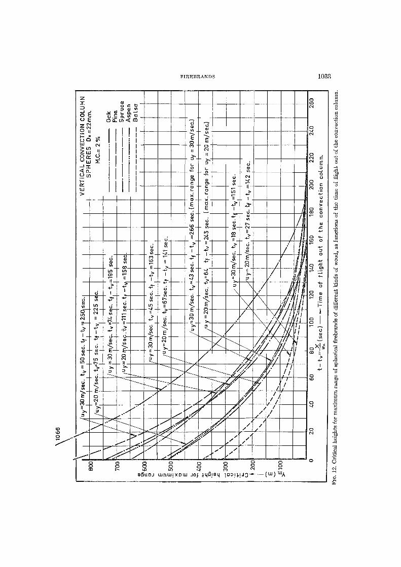
FIKEBBANDS 1033
o o CO
o o r-o o to 8
aBuoj uunuii
o o XDUU JOJ ^qBiaq TDOI^UQ- uu)UJA
D

1034 AERODYNAMICS I N COMBUSTION
1.0
• 4
,2
\. a EXPERIMENTAL RESULTS / W= 4 m/sec, A
10 mm. •< W _ . | Q // 4
rW= 4 m/sec. n 13 mm. i vV = io " *
„_ (W= 4 m/sec. o 1 5 m m . | w = 1 0 „ 0
& \ ° Q
• \ o \ n
EXPERIMENTAL RESULTS / W= 4 m/sec, A
10 mm. •< W _ . | Q // 4
rW= 4 m/sec. n 13 mm. i vV = io " *
„_ (W= 4 m/sec. o 1 5 m m . | w = 1 0 „ 0
ANA W =
V w= ^ 0
LYTICAL APROXIMATION ANA W =
V w= ^ 0
* . j
a
^
a • o
2 3 Time t ,m in .
1.0
.8
.4
Do = 15 mm. /
,o Do = 13 mm.
Do = 10 mm.
\ \ \
\ \ V
\
\ \ \ \ \
\ \
\ \
\ X p \ *
k \ \ \
I , V
- 1
/ \ *» 1 < \ ^ \ \
»\ \ \ \ 0
\ \ \ \
Time t , min.
FIG. 13. Empirical approximations of the laws of variation of density and diameter as functions of time for spherical firebrands.

FIREBRANDS 1035
FIG. 14 Comparison of the theoretical and experimental curves w/ — f{t) of a spherical firebrand.
0 400 800 1200 1600 2000 2400 2800 3200 3600 4000 4^00 4800 5200 5600 6000 Horizontal distance Xm
uy =30 m/sec (at X = 0) ux =20 m/sec (at X > 0 )
FIG. 15. Comparison of theoretical and experimental flight paths of spherical firebrands. Experimental paths are shorter, because the firebrands break off when they reach a small size, while theoretically they burn down to a zero diameter.

1036 AEEODYNAMICS IN COMBUSTION
p Air density pw Wood density 7], jS, 5 Parameters
ACKNOWLEDGMENT
The authors are indebted to Dr. A. Linan and Mr. J. A. Bollain, members of the research group, for their valuable collaboration.
REFEKENCES
1. DAVIS, K. P . : Forest Fire. Control and Use. McGraw-Hill, 1959.
Mr. R. Baldwin (Fire Research Station, Boreham Wood): Figure 2 of the paper shows that, for most of the lifetime of the particles considered, the rate of loss of weight is very large. In view of this, it is not apparent why in Eqs. (1) and (2) the force on the particle is not equated to the rate of change of momentum. If, for example, the particle is considered as surrounded by a layer of burning volatiles, the form of the drag force and, in particular, its dependence on the initial diameter A is not clear.
Dr. C. Sanchez Tar if a: The equation of the rate of change of momentum has to be applied following the total mass of a particle or system. When that equation is applied to a burning particle one has to consider the change of momentum of the solid par t remaining in the firebrand as well as the change of momentum of the gases exhausted from the firebrand owing to the combustion process.
If the obvious assumption is made tha t the combustion rate is the same all over the firebrand's surface, the mean relative velocity of the gases leaving the firebrand is equal to zero and the change of momentum of these gases does not appear in the equation. In other words, if at instant U we consider the firebrand, and at instant t% = k + At the firebrand plus the gases resulting from the combustion of mass Am during the infinetismal time At, we have:
F At = AS(mV) = m / 2V / 2 + Amg(V)g - mfiVfh
in which F is the total force acting on the firebrand, vif the mass of the firebrand, V/ its velocity, Amg the mass of the gases ejected (equal to m/i — m/2), and (V)g the mean absolute velocity of such gases. Since (V)<7 = V/2, we have
F At = (w/2 + Amg)Yf2 — m/iV/i = nif AV,
from which Eqs. (1) and (2), of the test, result. Any possible unsymmetrical combustion would
produce a very minor effect. After all, a firebrand is a burning particle carried by the wind and not a self-propelled rocket vehicle.
2. SANCHEZ TAKIPA, C , et al.: Open Fires and Trans
port of Firebrands. First Annual Report. Instituto Nacional de Tecnica Aerospacial. Madrid, 1962.
3. SANCHEZ TAEIPA, C , et al.: Open Fires and
Transport of Firebrands. Second Annual Report. Instituto Nacional de Tecnica Aerospacial. Madrid, 1963.
4. International Symposium on the Use of Models in Fire Research. National Academy of Sciences— National Research Council, Publication 786, 1961.
The aerodynamic drag is tha t which acts on the solid par t of the firebrand.
4
Prof. M. L. Blackshear (University of Minnesota): Has Sanchez Tarifa mapped out the blow-off velocity for cellulosic material, i.e., the velocity at which the burning envelope flame is blown into a wake flame or blown off altogether?
We have found tha t the dimension of cellulose cylinders do not change at first, when they burn with an envelope flame. With this in mind, I would like to know the reasons for relating weight loss directly with volume loss.
Dr. A. Broido (U.S. Forest Service): Cellulosic fuels burn in two processes in relative proportions, which are a function of inorganic impurities, among other things. Relatively pure cellulose will, in the early stages, leave a char with dimensions not too different from the original sample. With increased ash content, glowing is increased and the sample is reduced rapidly to an ash which can be blown off the sample readily. Thus, the rate at which sample size changes is definitely a function of the composition of the sample.
Dr. C. Sanchez Tarifa: We have observed flaming and glowing combustion in firebrands, but we have not observed wake flames. We studied wake flames on the occasion of a research program on droplets burning (The Combustion of Droplets, Influence of Forced Convection, Contract AF 61(514)-734 C. INTA, 1956), and we found tha t such type of combustion only takes place within a very narrow range of Reynolds Numbers, and that very seldom does a normal envelope flame change spontaneously into a wake flame.
We did not record the transition values from flaming to glowing as a function of the air velocities or of the Reynolds Numbers, since we were primarily interested in the laws of variation of the
COMMENTS

FIREBRANDS 1037
weight and aerodynamic drag of the firebrand, and because wood is not a suitable material for studying any particular combustion phenomenon, due to its nonhomogeneous characteristics.
Regarding Blackshear's second question, we
emphasize the combustion of cellulose is not the same process as combustion of wood. As pointed out by Broido, if cellulose contains some impurities its combustion process changes, and the volume of 1h<> sample decreases rapidly as it burns.