on the structure of grain/interphase boundaries and interfaces
TRANSCRIPT

1603
On the structure of grain/interphase boundariesand interfacesK. Anantha Padmanabhan*1 and Herbert Gleiter2
Review Open Access
Address:1School of Engineering Sciences & Technology and Centre forNanotechnology, University of Hyderabad, Prof. C. R. Rao Road,Hyderabad 500 046, India and 2Karlsruhe Institute of Technology(North Campus), Institute of Nanotechnology, Helmholtz Platz, 76344Eggenstein, Germany
Email:K. Anantha Padmanabhan* - [email protected]
* Corresponding author
Keywords:geometrical approach; grain/interphase boundaries; interfaces;representative volume; structural/basic unit model
Beilstein J. Nanotechnol. 2014, 5, 1603–1615.doi:10.3762/bjnano.5.172
Received: 25 March 2014Accepted: 27 August 2014Published: 22 September 2014
Associate Editor: P. Ziemann
© 2014 Padmanabhan and Gleiter; licensee Beilstein-Institut.License and terms: see end of document.
AbstractGrain/interphase boundaries/interfaces of varying misorientations, free volume fractions, curvatures and irregularities are present in
materials, both 3D and 2D, regardless of whether these materials are crystalline or amorphous/glassy. Therefore, a question arises
about the central idea on which a general description of grain/interphase boundaries/interfaces can and should be based. It is
suggested that a generalized model of a structural/basic unit (crystalline, non-crystalline or of any scale), which depends on the
interatomic (including electronic) interactions, the spatial distribution of the atoms and electrons, the number of atoms and free
volume fraction present in the structural/basic unit and the experimental conditions should serve the purpose. As the development
of a quantitative model, which reflects the effects of all these variables is difficult, slightly defective material boundaries are often
modeled by treating the entire boundary as planar and by using the concepts of crystallography. For highly disordered boundaries, a
description in terms of a representative volume, made up of a non-crystalline basic unit or a combination of such units, which
depend on interatomic (including electronic) interactions and forces, is advocated. The size, shape, free volume fraction and number
of atoms in the representative volume could differ with material composition and experimental conditions. In the latter approach, it
is assumed that all processes connected to a problem on hand is contained within this representative volume. The unresolved issues
are identified.
1603
IntroductionWhat is reported below is a full account of an invited talk deliv-
ered at "INT Physics Days", held at the Institute of Nanotech-
nology, Karlsruhe Institute of Nanotechnology (North Campus),
Germany, in November 2013. Successful attempts have been
made to understand some of the properties of materials by using
geometrical notions based on the symmetry of atomic arrange-
ments. There are also properties that critically depend on
defects and their distribution in materials. For explaining at
least some of the latter class of properties, ideas based on geom-
etry/crystallography are only of limited use [1]. At the other

Beilstein J. Nanotechnol. 2014, 5, 1603–1615.
1604
extreme is the notion of fractals, which has also found use in
describing microstructures [2,3].
The advent of metallic glasses [4] and nano-glasses [5,6] has
made it clear that a purely geometrical/crystallographic descrip-
tion of the structure of grain/interphase boundaries and inter-
faces (found in nano-glasses, where the glassy regions on either
side are non-crystalline or when an electrode–electrolyte system
is subjected to a voltage) is not likely to be tenable as a general
concept. It seems fair to say that even before the discovery of
metallic glasses, geometrical consideration was only a neces-
sary, but not sufficient, condition. For example, not all prop-
erties associated with grain boundaries (GBs) in all face-
centered cubic (fcc) metals, e.g., the presence or absence of an
orientation-dependence of the grain boundary energy, are iden-
tical, although the geometry of their atomic structure is the
same. In this communication we examine if there is a concept
that will allow a unified description of grain/interphase bound-
aries and interfaces in materials of different kinds. In our view
the concept of a “structural unit” [7], after sufficient general-
ization, could serve this purpose.
We suggest that, at the level of atomistics, the free volume frac-
tion and the number of atoms present in an ensemble should
also be treated as variables and that even the short-range order
that develops need not always lead to crystallinity. When the
ensemble is crystalline, we have referred to it as “structural
unit”. The non-crystalline variant is termed as “basic unit”. It is
further suggested that when these structural and basic units are
mixed in different proportions, one could obtain three different
types of grain/interphase boundaries/interfaces, viz., (a) crys-
talline boundaries that have long-range order, (b) general/
random high-angle boundaries and metallic/bulk metallic melt-
quenched glasses, which do not have long-range order, (c)
vapor-quenched and compacted nano-glasses, which, compared
with (b), contain in addition basic units of much greater free
volume fraction, which give rise to new properties. The descrip-
tion and the behavior of these three types of boundaries/inter-
faces are different. As a consequence of our research interests,
in the distant past H. Gleiter started from (a) downward. In
contrast, K. A. Padmanabhan started from (b). The underlying
thread of connectivity among the different ideas is the focus of
this paper.
ReviewStructural complexities: A qualitativedescriptionThe central idea in our approach is that the magnitude and
nature (metallic, ionic, covalent, molecular, etc.) of interatomic
(including electronic) interactions, number of atoms and free
volume fraction present in a system and the experimental condi-
tions are responsible for the development of the structural/basic
units. The final atomic configurations within these structural/
basic units will be decided by the minimization of total free
energy and, depending on experimental conditions, maximiza-
tion of entropy to the extent possible. The structures that are
formed need not always be crystalline, neither in the bulk nor in
the grain/interphase boundaries and interfaces. Each boundary/
interface will comprise many “structural/basic units”, all of
which are not necessarily identical. They could also be of rather
complex configurations, i.e., the structural/basic units that
constitute a grain/interphase boundary/interface could be a
collection of different ensembles of atoms whose number, size
and shape are governed by the well-known free energy equation
(1)
where U is the internal energy, P the pressure, V the volume,
T the absolute temperature, S the entropy, EN the energy
component that changes with the number of atoms (N) present
in the ensemble mainly because of topological reasons and Efv
is the energy associated with the free volume (fv) present in the
aggregate. (In the traditional form of Equation 1, the energy
contributions from N and fv are absorbed into U. But, as the
present discussion is concerned with the formation of the struc-
tural/basic units at an atomistic level, in our opinion, it is essen-
tial to treat N and fv also as independent variables for unequiv-
ocal inference.) “Δ” denotes the infinitesimal changes in the
above quantities due to a transformation/reaction. That is, the
size, number and shape of the structural/basic units will be
decided by the total number of atoms present in the system,
their mutual affinity or tendency to form compounds (if more
than one species is present), the initial temperature and the
energy possessed by the atoms at the beginning of the transfor-
mation, the final temperature, change in pressure and volume
due to a transformation, excess free volume and the rate of
cooling/quenching. To the best of our knowledge, a truly
random distribution of atoms is not found either in pure
elements or when more than one species is present in a material,
i.e., short-range order always exists. This is due to the presence
of interatomic (including electronic) attractive and repulsive
forces and the drive to decrease the free energy of the system.
Equation 1 applies to a cluster of atoms. When it gets embedded
inside a solid matrix, the energy associated with the insertion of
the atom cluster into the solid matrix also has to be included.
Eshelby [8] has explained how this can be done in a quantitat-
ive manner by approximating the shape of the basic unit to an
oblate spheroid. This will lead to an average value. For irreg-
ular ensembles, a quantitative procedure is yet to be developed.
Sometimes ensembles of a small number of atoms, which are
unique arrangements of lowest free energy, are formed [9].
Beilstein J. Nanotechnol. 2014, 5, 1603–1615.
1605
These configurations depend on the number of atoms and the
interatomic/chemical potential (including electronic interac-
tions and those due to their spatial distribution). It is not clear if
such configurations are possible in non-metals and if it is not
possible, the reason for the same is not known. Such a structure
may have an elastic modulus greater than that of the bulk. Free
energy increases even if the number of atoms is increased or
decreased by one [10]. When the number of atoms is larger than
N, for large N, the following states of matter are found: crys-
talline materials (conventional and nano-crystalline), melt-
cooled glasses and “ultra-stable” nano-glasses with distinctly
different properties. It is interesting that to this day nano-glasses
have been produced by using only compositions out of which
melt-quenched metallic glasses have been formed in the past. In
all these types of materials, the grain boundaries/interfaces have
a well-defined structure (not necessarily crystalline) with
respect to density, elastic properties and Mössbauer spectrum.
At present, there is no priori method of estimating the value of
N.
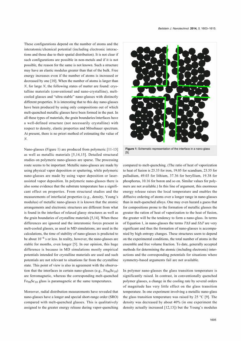
Nano-glasses (Figure 1) are produced from polymeric [11-13]
as well as metallic materials [5,14,15]. Detailed structural
studies on polymeric nano-glasses are sparse. The processing
route seems to be important: Metallic nano-glasses are made by
using physical vapor deposition or sputtering, while polymeric
nano-glasses are made by using vapor deposition or laser-
assisted vapor deposition. In polymeric nano-glasses there is
also some evidence that the substrate temperature has a signifi-
cant effect on properties. From structural studies and the
measurements of interfacial properties (e.g., density, Young’s
modulus) of metallic nano-glasses it is known that the atomic
arrangements and electronic structures are different from what
is found in the interface of relaxed glassy structures as well as
the grain boundaries of crystalline materials [5,14]. When these
differences are ignored and the interatomic forces present in
melt-cooled glasses, as used in MD simulations, are used in the
calculations, the time of stability of nano-glasses is predicted to
be about 10−6 s or less. In reality, however, the nano-glasses are
stable for months, even longer [5]. In our opinion, this huge
difference is because in MD simulations mostly empirical
potentials intended for crystalline materials are used and such
potentials are not relevant to situations far from the crystalline
state. This point of view is also in agreement with the observa-
tion that the interfaces in certain nano-glasses (e.g., Fe90Sc10)
are ferromagnetic, whereas the corresponding melt-quenched
Fe90Sc10 glass is paramagnetic at the same temperatures.
Moreover, radial distribution measurements have revealed that
nano-glasses have a longer and special short-range order (SRO)
compared with melt-quenched glasses. This is qualitatively
assigned to the greater energy release during vapor-quenching
Figure 1: Schematic representation of the interface in a nano-glass[5].
compared to melt-quenching. (The ratio of heat of vaporization
to heat of fusion is 25.33 for iron, 19.05 for scandium, 23.55 for
palladium, 49.03 for lithium, 37.36 for beryllium, 19.38 for
phosphorus, 10.16 for boron and so on. Similar values for poly-
mers are not available.) In this line of argument, this enormous
energy release raises the local temperature and enables the
diffusive ordering of atoms over a longer range in nano-glasses
than in melt-quenched alloys. One may even hazard a guess that
for compositions prone to the formation of metallic glasses the
greater the ration of heat of vaporization to the heat of fusion,
the greater will be the tendency to form a nano-glass. In terms
of Equation 1, in nano-glasses the terms TΔS and SΔT are very
significant and thus the formation of nano-glasses is accompa-
nied by high entropy changes. These structures seem to depend
on the experimental conditions, the total number of atoms in the
ensemble and free volume fraction. To date, generally accepted
methods for determining the atomic (including electronic) inter-
actions and the corresponding potentials for situations where
symmetry-based arguments fail are not available.
In polymer nano-glasses the glass transition temperature is
significantly raised. In contrast, in conventionally quenched
polymer glasses, a change in the cooling rate by several orders
of magnitude has very little effect on the glass transition
temperature. In one experiment involving a metallic nano-glass
the glass transition temperature was raised by 25 °C [9]. The
density was decreased by about 40% (in one experiment the
density actually increased [12,13]) but the Young’s modulus

Beilstein J. Nanotechnol. 2014, 5, 1603–1615.
1606
was similar to or higher than that of the crystalline and the
denser, conventional glassy counterparts [9,10,14]. This could
indicate a change in the nature of electronic interactions, e.g.,
from metallic to covalent bonding. The heat capacity was 20%
lower, but the enthalpy and the kinetic stability were higher
compared with the melt-quenched glass variant. The rule of
thumb that thermal stability is proportional to density is
violated. (With a qualification “as long as the nature of the
bonding between atoms does not change”, the above rule of
thumb could still be useful.) Interfaces in nano-glasses are often
wider than in crystalline materials. It stands to reason that when
a material is quenched from the temperature of vaporization, the
quenched-in free volume will be significantly more than when
the atoms are quenched in from the melt-quenching tempera-
tures. This can explain the lower density of the nano-glasses.
In a recent study [16], it has been shown that lattice expansion
or amorphization makes EuTiO3 ferromagnetic, although the
stable phase of crystalline EuTiO3 is antiferromagnetic. Ferro-
magnetism increases with an increase in the lattice volume of
EuTiO3. Amorphization also has a similar effect on ferromag-
netism. This observation has been explained in terms of compe-
tition between ferromagnetic and antiferromagnetic interactions
among the Eu2+ ions. Similar ideas could also be relevant in
understanding the development of ferromagnetism in Fe90Sc10
nano-glasses, which in the melt-spun and crystalline states is
paramagnetic [15].
In fact even as-prepared nano-glassy powders of metallic ma-
terials do not have a core–shell structure (not more than a
monolayer in any case) and exhibit a Mössbauer spectrum
similar to that of the melt-cooled glasses, which indicates para-
magnetism [15]. However, once the powders are cold-
compacted at different pressures, a six-line spectrum character-
istic of ferromagnetism is obtained, i.e., ferromagnetism origi-
nates at the interface phase in metallic nano-glasses formed by
compaction (Figure 2). This view is supported by the observa-
tion that the volume fraction of the ferromagnetic material
scales with the volume fraction of the interfaces [15]. This
raises a question: How much lattice expansion can be tolerated
in the boundary regions (compared to the grain interior) before
the use of MD simulations, which consider the inter-atomic
forces in the grain/interphase boundaries/interfaces to be similar
to those present in the grain interior, does no longer provide
valid results? The answer is not known at present.
Nano-glasses, compacted in the above fashion, are very stable
(compared with their melt-quenched variants) even at tempera-
tures close to the crystallization temperature. To date, the width
of the glass–glass boundaries has not increased by a factor of
more than two even after annealing the specimens close to the
Figure 2: (a) As-quenched (from the vapor phase) nanoglassy grainsexhibiting paramagnetic behavior, and (b) quenched from vapor phaseand compacted nanoglass, in which the interface matter exhibits ferro-magnetic behavior. Adapted from [15]. Copyright 2013 American Insti-tute of Physics.
glass transition temperature for several hours. (Usual molecular
dynamics simulations, in contrast, suggest that the glass–glass
boundaries would delocalize in a few nanoseconds at 100 K.)
These observations emphasize that detailed computations will
be necessary in order to determine the interatomic forces in
solids with modified structures/basic units and reduced densi-
ties for different materials. There are some works in which such
computations based on ab initio methods, e.g., tight binding
model, are described [17,18]. Similar ab initio calculations have
also been undertaken for boron. It has been shown that the
structural details of beta-rhombohedral boron, such as vacan-
cies and extra occupancies, are due to the details of the elec-
tronic structure requirements and not just structural defects [19-
21]. In these cases, the formation of structural/basic units will
depend on the separation between the atoms and the nature
(metallic, ionic or covalent) of the electronic interactions and
the magnitude of the interatomic forces. The individual struc-
tural/basic units and the free volume present in them will
depend on the number of atoms present in the ensemble, the
start and end temperatures and other experimental conditions
including the rate of heating and quenching. In view of the
above complexities, an ad hoc approach, viz., the correction of
existing potentials over short distances, as it is done while simu-
lating displacement cascades under irradiation, may be
attempted. But there is no guarantee that such empirical fits can
be of universal relevance. In a recent experiment, even when a
nano-glass was cut into very thin slices, delocalization did not
take place [22]. There is a need to understand this remarkable
stability.
Taking the above points into account, we arrive at Figure 3, a
qualitative pictorial representation in free energy–configuration

Beilstein J. Nanotechnol. 2014, 5, 1603–1615.
1607
Figure 3: Schematic representation of phase transformations in the free energy–configuration space.
space. Depending on the degree of metastability, six basic
configurations are possible: (1) the maximum degree of packing
and stability of the structure is obtained with a small number of
atoms. We have already pointed out the limitations in the under-
standing of such structures at present. This configuration is
different from the rest, as the others deal with a situation in
which the number of atoms is above a critical value (not yet
predicted). When one quenches the atoms from the vapor phase,
depending on the elements present, concentration and experi-
mental conditions, one may get (2) a nano-crystalline material,
or (3) a nano-glassy material. These are metastable structures.
Comparing the two, a nano-crystal appears to be more stable
than a nano-glass. (In a recent experiment, annealing led to the
precipitation of nano-crystals from a nano-glass [14]). The
nano-glasses have properties similar to those of melt-cooled
metallic glasses. The quenching is drastic and the structure is
metastable. A nano-glass may also be obtained by amorphizing
a nano-crystalline material, e.g., by repeated rolling and folding
[23]. When such nano-glassy grains are subjected to a suffi-
ciently high pressure (although the exact threshold value has not
been established yet), the activation energy required to trans-
form them into an “ultra-stable” nano-glassy state is provided.
(It may also be possible to supply an equivalent amount of
energy by heating. But this hypothesis is yet to be tested.) As
noted earlier, in view of the much larger energy release (energy
stored as a result of quenching from the vapor phase and trig-
gered by subsequent application of pressure) and the conse-
quent local temperature rise, the transformation becomes non-
adiabatic. Therefore, an entropy-dominated transformation, in
which the atoms are able to reach more stable configurations,
comes into play. This gives rise to (4) an “ultra-stable” nano-
glass. It is interesting that even when such a nano-glass is sliced
very thin, its stability is intact. It is important to find out the
minimum thickness of this slice or the number of atoms in the
aggregate necessary to retain this enhanced stability. (5)
Metallic glasses or bulk metallic glasses with basic units similar
to those present in the nano-glass described in (3) (the differ-
ence is only in the free energy of the system) may be obtained
directly by melt-quenching. (6) The melt-quenched glass gets
converted into a nano-crystalline or crystalline material above
the crystallization temperature, when the required activation
energy becomes available. Alternatively, crystalline materials
can also be produced directly by casting. Within each state,
depending on the experimental conditions, the free energy of
the system could change, i.e., each of these states of matter can
be present with different free energies. Although Figure 3 is
schematic and not to scale, based on empirical observations it is
suggested that the relative stability of the different states of
matter appears to be as indicated in the diagram. This brings
one to Kauzmann’s entropy crisis [24-26], which suggests that

Beilstein J. Nanotechnol. 2014, 5, 1603–1615.
1608
if the entropy of many supercooled liquids is extrapolated to
low temperature, the amorphous state is predicted to have a
lower entropy level than the highly ordered crystal well above
absolute zero. In our opinion, such a linear extrapolation may
not be correct. This is because the adiabatic approximation, on
which the extrapolation is based, is not valid in these cases (see
above and also later).
It is emphasized that in each state depending on the experi-
mental conditions and the number of atoms that form the struc-
tural/basic unit, the interatomic spacing and the free volume
fraction could be different. When the lattice expansion is
beyond a certain limit, the nature of bonds in the grain interior
will be of a different kind compared with that in the interface
regions. Then, differing interatomic potentials and distinctly
different properties can be found in the grain interior and the
interface matter respectively and this is what is seen in the case
of “ultra-stable” nano-glasses. The maximum allowable lattice
expansion, at which the approximation that the interatomic
potential in the grain interior and at the grain/interphase
boundary/interface can be considered to be similar is still valid,
is yet to be determined. For a complete description of the atoms
arranging themselves into structural/basic units in the interface
region, a more detailed characterization of the bonds (including
the differences compared with the grain interior) is required.
A number of issues need to be addressed for a quantitative
understanding of the structure and properties of “ultra-stable”
nano-glasses. As stated earlier, adiabatic approximation, which
leads to electronic configurations of atoms in the ground and
transition states being identical, may not be permissible. For
example, reduced atom mobility at low temperatures may alter
interatomic distances and free volume fraction. Hence the elec-
tronic configuration and the nature and magnitude of interac-
tions could change. This is particularly important for transition
metals. It is not easy to quantify the coordinated nature of
movement of atoms. Moreover, the role of anharmonicity and
internal stresses in determining the properties of nano-glasses is
not clear. It will be quite a while before the above theoretical
problems are solved rigorously. But, solutions to practical prob-
lems cannot wait for long. So approximate/semi-empirical solu-
tions are needed.
Limiting approximationsUpper limit (the simplest case)The different ideas used to describe crystalline matter were
recently examined, including situations in which long-range
periodicity is missing, e.g., general high-angle grain boundaries
[27]. Here it is important to note that in crystalline materials and
melt-quenched metallic glasses the electronic structure, if at all
different in grain/interphase boundary/interface regions
compared with the grain interior, is due to an increase in defect
density, as found, for example, in nano-crystalline materials
produced by plastic deformation [28]. This increases only the
interatomic distances in the boundary region compared with the
grain interior to a limited extent, without changing the nature of
the bonds. (Then, the boundaries become weaker than the grain
interior because of the larger interatomic distances.) Therefore,
for this class of materials molecular dynamics (MD) simula-
tions may be used to determine the structure of grain/interphase
boundaries/interfaces. (As these involve the use of empirical
potentials, their relevance has to be tested first against experi-
mental results for each case.)
The upper-limit approach treats the boundaries to be planar (an
approximation). Further simplification is possible if they are
classified either as tilt or twist boundaries. Then elegant treat-
ments based on crystallographic and geometrical concepts are
possible. Those who have examined grain boundaries under a
microscope are aware that flat boundaries are seen very rarely
and that it is not easy to classify a real boundary uniquely as a
tilt or twist type. Often, one encounters mixed-types and curved
surfaces. In addition, most of the experiments are on bound-
aries of metallic materials. These restrictions require a careful
consideration whether an approach based on crystallographic
concepts is applicable.
In a grain boundary of a polycrystalline material, the structure is
periodic because the boundary conditions, i.e., those introduced
by the crystals on both sides, are periodic. For static flat bound-
aries, the concept of coincidence site lattice (CSL) of Kronberg
and Wilson [29] may be used, if the misorientation between two
grains is such that it will allow certain atoms at the boundary to
belong to both the crystals that form the boundary. However, if
the misorientation deviates slightly from this special relation-
ship, there will be a tendency to form low energy clusters, if
necessary by adding a unit of a different structure of a low
energy cluster, which belongs to another special relationship of
low energy. This way, many different kinds of low energy clus-
ters are formed to yield a given orientation relationship. In other
words, the boundary structure is a 2D array of low energy clus-
ters that form the transition layer between two crystal lattices of
a given misorientation. A consequence is that low energy rela-
tionships are not necessarily CSLs. (However, some low energy
grain boundary orientations may have coincident atom sites,
which would qualify them as CSLs.) This has been proved in
several experiments involving relaxed boundaries. For example,
in rotating sphere experiments low energy relationships varied
as a function of the kind of chemical bonds and temperature
[30], an observation which cannot be accounted for by the
purely geometrical CSL model. The latter would predict the
same special boundaries for the same lattices and given misori-

Beilstein J. Nanotechnol. 2014, 5, 1603–1615.
1609
entation. The last mentioned paper also demonstrates that there
are many CSL orientations that do not result in low energy
boundaries. Likewise, some cusps in the energy–misorientation
plots disappear with increasing temperature, although the order
in the grain boundary remains intact below the melting point.
This shows that the effects of interfacial entropy are significant
[31]. In addition, the average thermal expansion of grain bound-
aries is 2.5–5 times that of the crystalline grain interior. A
purely geometrical model cannot account for such a differential
change with temperature [32]. The effect of pressure is also
significant. The PΔV term causes some cusps in the
energy–misorientation plot to disappear [33]. This is evidence
for pressure-induced structural changes in grain boundaries and
implies that grain boundaries have a larger free volume and
larger interatomic distances than the grain interior and that these
can be altered by compressive stresses of sufficiently high
magnitude. By carrying out massive MD simulations of relaxed
boundaries, Sutton and Vitek [34-36] have shown that the struc-
tural unit model, coupled to a realistic potential, results in a
description, which is consistent with the current understanding
of the structure of grain boundaries (the “good” crystal part) and
that the predictions are in line with high-resolution TEM results
concerning grain boundaries.
However, the CSL concept, which is very simple, can be used
to advantage in certain situations, e.g., to explain low-angle and
twin boundaries. In case of small angle boundaries the CSL
description reduces to the Read–Shockley model [37] and is
obtained by placing a dislocation core at regular intervals along
the grain boundary. A simple atomistic model for the formation
of annealing twins was proposed [38] to be the result of a 2D
nucleation process on the {111} planes of growing grains of an
fcc lattice. In this case, every atom at the boundary will be in a
CSL position. It has already been pointed out [39] that the twin
boundary is a first-order twin relationship and should be distin-
guished from high-angle boundaries. So the use of the CSL
concept to describe “high-angle boundaries” in general [40] is
perhaps not correct. However, there are boundaries beyond the
low-angle range, which can be described as “sigma boundaries”
[39] or “vicinal” boundaries [41], for which also the CSL
concept, including the formation of a displace–shift–coincide
(DSC) lattice, could be physically meaningful, with certain
limits imposed on the permissible deviations from the CSL pos-
ition. In this category there are four models [39,42-44], of
which the one of Palumbo and Aust [39,45,46] perhaps matches
experimental results (concerning boundary corrosion) more
accurately. However, the Brandon criterion [42] is by far the
most popular. Two more points may be noted: (a) There is little
support for the general usefulness of purely geometrical models
in determining grain boundary energies [41]. (b) The demon-
stration that for specific twinning operations (i.e., 180° rota-
tions) along rational indices [hkl], a 3D coincidence site lattice,
having Σ = h2 + k2 + l2 and a boundary (i.e., twinning) plane
{hkl} is generated in cubic crystals [47] follows directly from
Euler’s transformation rules, i.e., the mathematics is correct, but
well-known.
Very recently, Raabe and coworkers [48-50] have examined the
relevance of the CSL concept in understanding the two prop-
erties of segregation and corrosion by using TEM, atom probe
tomography (APT) and a “pseudo” 3D-EBSD approach. The
major conclusions are as follows. (a) Segregation for low-angle
grain boundaries scales with the number of dislocations, i.e., it
increases with an increasing boundary misorientation in the
low-angle region. (b) For high-angle GBs, the coincidence
number alone is not a decisive parameter, but knowledge about
the GB plane is essential, i.e., whether the GB is coherent or
not. For example, for Σ3 twins only fully coherent GBs with
(nearly exact) (111) GB planes exhibit low segregation. (c) The
occurrence of a certain coincidence lattice is not a sufficient
criterion for a GB to be “special”. This is because the coinci-
dence site lattice defines only three (out of the five) degrees of
freedom of a GB and it does not provide any information about
the orientation of the GB plane and the degree of coherency in
it. For instance, the Σ9 GB, in spite of being a low ΣCSL
boundary, does not exhibit “special” behavior regarding its
resistance to segregation. This is attributed to the fact that the
studied Σ9 boundary is not symmetric, i.e., the Miller indices of
the boundary plane measured with respect to the two mutual
grains are not identical, and therefore, also do not correspond to
a coherency plane. (d) In case of corrosion, only the low-angle
boundaries and the Σ3 and Σ5 boundaries do not get attacked.
Other low-angle boundaries get attacked to a low extent. But
other low ΣCSL boundaries, Σ3 ((81d) (ideally ≈60.4° <443>;
but ≈60.1° <443> in the experiment; a fourth order twin which
qualifies as Σ3 according to the Brandon criterion)), Σ27 bound-
aries (a third-order twin boundary, often formed in materials
with low stacking fault energies), and random high-angle GBs
get attacked severely. A Σ9 boundary is attacked to a moderate
to high degree. Sometimes even some random high-angle grain
boundaries do not get attacked. All the above calculations
regarding the boundaries are based on the deviations allowed by
the Brandon criterion, which seems to be too “generous”. Thus
the usefulness of the CSL concept in relating the structure to the
properties beyond low-angle and coherent boundaries is not
clear.
Notwithstanding the above statements, it is safe to say that the
crystallographic approach has helped to achieve a remarkable
simplification of a problem, as long as the crystals contain only
a small number of defects. Then, idealization in terms of planar
boundaries, for which crystallographic notions make perfect

Beilstein J. Nanotechnol. 2014, 5, 1603–1615.
1610
sense, is possible. The defects are taken into account by
breaking the symmetry rules using well-calibrated local consid-
erations, again derived from geometrical notions. But, when the
defects are numerous and the boundaries are far from being
linear, e.g., a general high-angle grain boundary in which long-
range periodicity is also missing, certain parts of the boundary
contain significant free volume and describing them in crystal-
lographic terms becomes difficult. The approach breaks down
and an alternative description based on the nature and magni-
tude of interatomic forces becomes essential. It must be
mentioned that for the latter approach, which is more realistic/
rigorous, so far only the method (MD simulations) of working
out the structure of grain boundaries by assuming suitable
empirical interatomic potentials for simple materials has been
spelled out. The procedures for extending this technique to
include alloys of commercial significance are yet to be devel-
oped [27]. Enormous efforts that will involve ab initio methods
and take into account interatomic (including electronic) interac-
tions will be necessary to improve the situation.
Lower limit: the concept of representative volume(with a focus on the region of disorder)It was pointed out [27] that a geometry-based approach does not
seem to lead to useful results in case of general high-angle grain
boundaries, in which long-range periodicity is missing and
significant free volume is present at certain misorientation-
dependent locations in whose vicinity the structure cannot be
described in crystallographic terms. But the high-angle
boundary is the most important structural element needed for
describing superplastic flow. Interestingly, superplasticity is
present in both crystalline and glassy materials [51-53]. Postu-
lating: (a) that the rate-determining process during superplastic
deformation is confined to basic units (not crystalline) around
free volume sites in the high-angle grain/interphase boundary/
interface, and (b) that the sliding along grain/interphase inter-
face/boundaries is the rate-determining process, steady state
superplastic deformation has been explained quantitatively by
using the concept of “representative volume”, often invoked in
analyses of transport phenomena in large systems (involving
heat, mass and momentum transfer). The representative volume
is assumed to be large enough to allow the operation of the unit
processes relevant to a problem on hand. Simultaneous opera-
tion of these unit processes in different representative volumes
that are present throughout the system and the summation of
their effects is assumed to result in the overall response. Such
an approach presupposes that the real problem is so complex
that a rigorous analysis in all aspects is not possible. (The
assumption of “representative volume” is used even when the
upper limiting case, based on the assumption that grain bound-
aries are flat, is involved, e.g., Nabarro–Herring (N–H) creep,
even though this is not stated explicitly. In N–H creep, for
example, it is assumed that what occurs in a cubic grain is
repeated all over the sample.) For a quantitative understanding
of steady state superplastic flow [53-57], the basic unit of
boundary/interface sliding, the representative volume, is
assumed to be an oblate spheroid of about five atomic diame-
ters along the boundary plane and about two and a half atomic
diameters (average grain boundary width [58]) in the perpendic-
ular direction. (A deformation of oblate spheroids of such
dimensions along the interface between glassy regions in case
of metallic glasses would lead to the formation of shear trans-
formation zones, described by Argon [59] and others.) As
mentioned above, the basic units of boundary/interface sliding
are defined around free volume sites, which are present at
discrete places characteristic of the interatomic forces and the
boundary misorientation. The sequential shear of such oblate
spheroids, when it reaches the end of a boundary, results in a
boundary-sliding offset and, in contrast, deformation would be
blocked, if a triple junction were encountered. For continued
boundary sliding, this sliding process has to develop to a meso-
scopic scale through the formation of plane interfaces. The
driving force for the formation of such plane interfaces is the
minimization of the free energy of the system and the fact that
for this configuration, the applied stress does maximum work
(principle of maximum work of G. I. Taylor). These processes
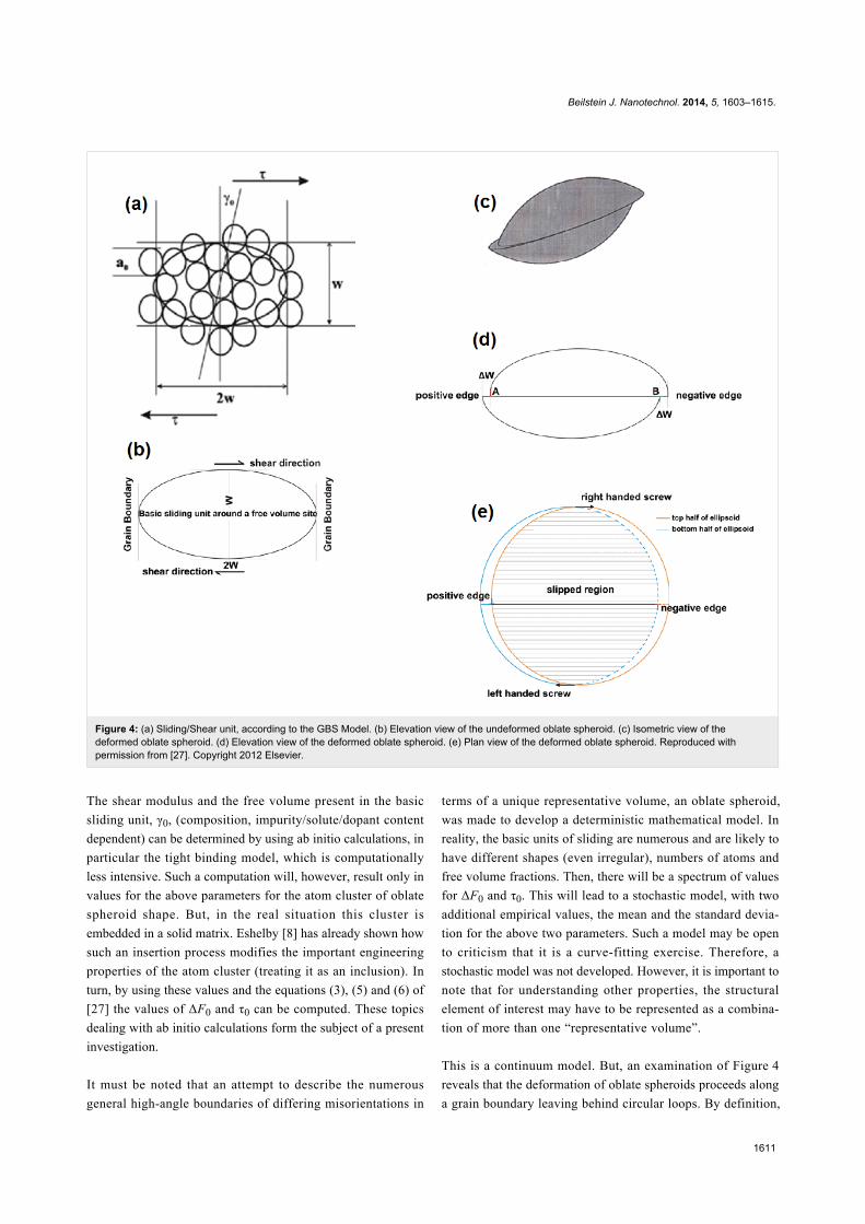
are illustrated in Figure 4 and Figure 5. Depending upon the
boundary misorientation, which, along with the nature and
magnitude of the interatomic forces, decides the free volume
present inside an oblate spheroid and free volume fraction along
a boundary, the neighborhood of the deforming oblate spheroid
would be different. As a result, the internal stress distribution
that develops due to sliding will change with material chem-
istry, boundary misorientation, stress, and strain. A way of
quantifying the internal stress distribution is then spelled out
[54]. It is pointed out here that the effects of composition,
atomic arrangement in the oblate spheroid, impurity/solute/
dopant effects and free volume present are captured into two
phenomenological parameters, the free energy of activation,
ΔF0, and the threshold stress necessary for the onset of meso-
scopic boundary/interface sliding, τ0. The above ideas have
been shown to be useful in understanding quantitatively super-
plastic deformation in micro-grained and nanostructured
pseudo-single phase as well as micro-duplex metallic materials,
ceramics, ceramic composites, intermetallics, dispersion
strengthened alloys and an alloy containing quasi-crystalline
particles [53]. Very recently, it has been found to be useful for
interpreting superplastic flow in bulk metallic glasses also
(Buenz, J.; Padmanabhan, K. A.; Wilde, G., unpublished work).
Experimental support for mesoscopic boundary sliding/plane
interface formation and near-random grain rotation due to the
rate-determining boundary/interface sliding process is also
available. These are summarized in [53-57,60-62].
Beilstein J. Nanotechnol. 2014, 5, 1603–1615.
1611
Figure 4: (a) Sliding/Shear unit, according to the GBS Model. (b) Elevation view of the undeformed oblate spheroid. (c) Isometric view of thedeformed oblate spheroid. (d) Elevation view of the deformed oblate spheroid. (e) Plan view of the deformed oblate spheroid. Reproduced withpermission from [27]. Copyright 2012 Elsevier.
The shear modulus and the free volume present in the basic
sliding unit, γ0, (composition, impurity/solute/dopant content
dependent) can be determined by using ab initio calculations, in
particular the tight binding model, which is computationally
less intensive. Such a computation will, however, result only in
values for the above parameters for the atom cluster of oblate
spheroid shape. But, in the real situation this cluster is
embedded in a solid matrix. Eshelby [8] has already shown how
such an insertion process modifies the important engineering
properties of the atom cluster (treating it as an inclusion). In
turn, by using these values and the equations (3), (5) and (6) of
[27] the values of ΔF0 and τ0 can be computed. These topics
dealing with ab initio calculations form the subject of a present
investigation.
It must be noted that an attempt to describe the numerous
general high-angle boundaries of differing misorientations in
terms of a unique representative volume, an oblate spheroid,
was made to develop a deterministic mathematical model. In
reality, the basic units of sliding are numerous and are likely to
have different shapes (even irregular), numbers of atoms and
free volume fractions. Then, there will be a spectrum of values
for ΔF0 and τ0. This will lead to a stochastic model, with two
additional empirical values, the mean and the standard devia-
tion for the above two parameters. Such a model may be open
to criticism that it is a curve-fitting exercise. Therefore, a
stochastic model was not developed. However, it is important to
note that for understanding other properties, the structural
element of interest may have to be represented as a combina-
tion of more than one “representative volume”.
This is a continuum model. But, an examination of Figure 4
reveals that the deformation of oblate spheroids proceeds along
a grain boundary leaving behind circular loops. By definition,

Beilstein J. Nanotechnol. 2014, 5, 1603–1615.
1612
Figure 5: Development of mesoscopic grain/interphase boundary sliding. Shaded grain boundaries of rhombic dodecahedral (a) and tetrakai decahe-dral (b) grains within which the rate-determining process is confined. (c) Resulting planar interfaces (along XY, X’Y’, X”Y”, etc.), which are 2D sectionsof an aggregate of grains of equal size and rhombic dodecahedral shape. When the atoms located in the shaded regions are moved by the extensionof the boundaries normal to the shear direction to reach the sliding boundary planes, a plane interface results. (d) Shear-stress driven movement of aboundary triple junction to lower the overall free energy of the system. (a) and (b) reproduced with permission from [54], Copyright 1996 ManeyPublishing and (c) and (d) reproduced with permission from [56], Copyright 2004 Elsevier.
they constitute dislocation loops of zero Burgers vector in the
Volterra sense. (They cannot, however, be described in terms of
crystallographic concepts because the loop formation displaces
the basic sliding unit in the direction of stress only by about a
tenth of the interatomic spacing in the boundary region.) In this
sense, the speculation found in the literature that the motion of
extrinsic boundary dislocations could cause grain boundary/
interface sliding is justified. Assuming the extrinsic boundary
dislocations to be discrete, Nazarov and coworkers (for a
summary see [63]) have been able to predict accurately the
grain boundary excess energy and the additional free volume/
lateral expansion found in severely plastically deformed ma-
terials. Now Nazarov and Valiev (personal communication)
believe that their model is “mesoscopic” and thus the need to
explain the extrinsic boundary dislocations in terms of a crystal-
lographic notion is dispensed with. By using MD simulations,
an investigation has just been started to verify whether the prop-
agation of “dislocation loops” in our continuum approach is
equivalent to the propagation of extrinsic boundary dislocations
assumed for boundary sliding in the analysis of Nazarov et al.
[63].
More complicated situationsSo far two extreme cases were examined in detail. (a) Consid-
ering the entire boundary to be planar and understanding the
responses of the boundaries to external stimuli by using notions
based in crystallography. This covers all kinds of crystalline
grain boundaries, excluding random high-angle grain bound-
aries. Here two alternative approaches are found: (i) a purely
geometrical approach based on coincidence site lattice concept,
and (ii) the structural unit model, which emphasizes that struc-
tures (including grain boundaries/interfaces) develop because of

Beilstein J. Nanotechnol. 2014, 5, 1603–1615.
1613
the presence of interatomic (including electronic) interactions/
forces and, for a given set of experimental conditions, because
of a competition between the minimization of free energy and
the maximization of entropy of the system. A survey of
contemporary literature reveals that the latter approach is the
favored one. However, in some situations, the former (geomet-
rical) approach could help solve problems easily, albeit approxi-
mately.
In the lower bound approximation, by assuming that all steps
involved in the rate-determining process are found inside a
basic unit of atoms in the boundary of atomistic dimensions,
and where the structure is not crystalline and more open than in
the grain interior and the rest of the boundary, a mathematical
treatment has been developed for the high-angle boundary
dominated process of superplasticity, which is observed in both
crystalline and glassy materials. These basic units are present at
various places in the boundary between (crystalline) structural
units, with their (basic units) locations being decided essen-
tially by the boundary misorientation and the nature and
strength of the interatomic forces. The shape, size and prop-
erties of the basic unit is the result of a complex interaction
between interatomic (including electronic) forces, free energy
minimization and entropy maximization [51-57]. When no
assumptions are made about the shape and size of the basic unit,
the number of atoms present in it and the enclosed free volume
fraction also are variables. For mathematical development, the
shape of the basic unit was approximated to an oblate spheroid
of 5 atomic diameters in length and 2.5 atomic diameters in
height. This results in a deterministic model that estimates the
overall (average) response of the system in the steady state to an
external stress with regard to some useful properties. Needless
to say, for studying local and topological effects, the shape, size
and free volume fraction of every basic unit in the boundary
should be considered, along with their neighborhoods. This is a
formidable problem and is yet to be solved.
It is seen experimentally that in many cases, in addition to
short-range order, intermediate order as well as long range order
and periodicity/quasi-periodicity (in the latter case, crystalline/
quasi-crystalline matter) are present. Then, it will be possible to
start with a “representative volume” of larger dimensions, with
accompanying modifications/simplifications. For the simplest
case of the entire boundary being regarded as a plane, this has
been done by using elegant geometrical/crystallographic
notions.
The “ultra-stable” nanoglasses, produced by quenching from the
vapor phase and the powders subsequently compacted, seem to
be in a category of their own, whose quantitative description
would require the conversion of the free volume fraction in the
oblate spheroids of the lower limit to a widely varying variable
(with far more free volume fraction than what is needed to
explain the structure of random high-angle boundaries and melt-
quenched metallic glasses) so much so that when the free
volume fraction exceeds a critical value (yet to be calculated)
the very nature of the chemical bonds between the atoms for the
same chemical composition changes, e.g., from metallic to
covalent. In boundaries of this type of nano-glasses, such highly
expanded basic units coexist with (crystalline) structural units
(responsible for the unique type of short-range order seen),
which could fit into the rest of the boundary by a process
similar to what is envisaged in the “lock-in” model [64,65], and
the type of basic units considered while discussing high-angle
grain boundaries/melt-quenched metallic glasses/superplas-
ticity. Melt-quenched metallic glasses and nano-glassy powders
(not compacted), in contrast, are not likely to have the highly
expanded basic units in which the nature of the chemical bonds
has changed. In this sense, melt-quenched metallic glasses and
nano-glassy powders are similar to a relaxed high-angle
boundary, with only a difference in the free volume fraction, the
proportion of structural and basic units, the spatial distribution
of these units and the free volume. The experimental observa-
tion (S. V. Divinski, personal communication) that diffusivity in
melt-quenched metallic glass is between those of volume diffu-
sion and grain boundary diffusion in crystalline materials, all of
which are less than that of severely plastically deformed grain
boundaries, seems to be in line with this idea. Construction of
3D structures that incorporate these ideas is likely to be a chal-
lenge.
There is also a difference in the boundary between two solitons
(crystals), which is an inter-crystalline/interphase boundary, and
the boundary between two glassy regions (grains) that are not
solitons. If one examines the distribution width of the hyperfine
field of the glass component and the interfacial component in
Figure 2, one finds that they are comparable. Both phases
(glassy component and the interfacial component) fluctuate
structurally within a specimen by the same amount. In contrast,
in a poly-crystalline or nano-grained material, the component of
the spectrum associated with the crystallites is very narrow,
while the one associated with the boundaries is so broad that it
appears almost like a uniform background, i.e., there are wide
fluctuations in the structures of the boundaries. This difference
is traced to the fact that a glass has shear modulus that tends to
zero as time tends to infinity. In case of the interfacial phase, if
there is a minimum in the free energy–free volume space at a
different free volume fraction than in the glassy component, all
the boundaries in the nano-glass will, in the long run, work their
way into that minimum. Evidently, such a process is not
possible in inter-crystalline boundaries because they will have a
“structural memory” due to the given misorientation between

Beilstein J. Nanotechnol. 2014, 5, 1603–1615.
1614
the crystals, which have time-independent shear moduli. For
further consideration, the reader is referred to [22].
Finally, there is the question why long-range order and period-
icity/quasi-periodicity should develop at all in materials. We see
the following possibilities for a mathematical development. (a)
The total free energy of the system becomes less than what is
the case in their absence (the traditional approach). (b) The
total free energy of the system, which is a function of several
variables, experiences a bifurcation at some point. If this
function has a value more or less than a certain figure (which
will depend on the way the function is defined), it will
have long-range periodicity/quasi-periodicity and be
crystalline/quasi-crystalline. Otherwise, the structure would be
non-crystalline. (c) The fractal nature of microstructures has
been well documented [2,3], including that present in a nano-
glass [14]. Is it possible that the development of long-range
periodicity/quasi-periodicity and crystalline/quasi-crystalline
structure corresponds to the “strange attractors” of the Chaos
theory?
ConclusionIt is concluded that a generalized structural/basic unit (crys-
talline, non-crystalline or of any scale) model, which takes into
account the interatomic (including interelectronic) interactions,
the spatial distribution of atoms and electrons, the number of
atoms and free volume fraction in the ensemble, the starting and
finishing temperatures, rate of heating/cooling and other experi-
mental conditions can describe in a general manner the struc-
tures that develop in grain and interface boundaries in crys-
talline/quasi-crystalline and glassy materials. As a quantitative
development that takes all these variables into account is rather
difficult, we have arranged them in increasing order of
complexity. By assuming the boundaries to be flat/planar,
simplified solutions can be obtained by using crystallographic
notions. At the other extreme, by using the concepts of short-
range order and “representative volume”, which assumes that a
relatively much smaller volume taken from the whole is large
enough to simulate all relevant steps connected with a rate-
determining process, simplification is achieved to explain a
high-angle boundary dominated process like superplasticity,
found in crystalline as well as melt-quenched (bulk) metallic
glasses. The method for a quantitative description of more com-
plex situations, where (crystalline) structural units, basic units
(which include some free volume and crystallinity is absent, as
found in high-angle grain boundaries and melt-quenched
metallic glasses) and non-crystalline regions of far greater free
volume fraction (where the nature of interatomic (including
electronic) interactions could be different from that in the grain
interior) which coexist (as found in compacted nano-glasses), is
yet to be developed.
AcknowledgementsThe authors thankfully acknowledge interesting discussions
with Dr. S. V. Divinski and Prof. A. A. Nazarov.
References1. Cottrell, A. H. Closing Address, Dislocations and Properties of Real
Crystals. In Proc. Conf. To Celebrate 50th Anniversary of the Conceptof Dislocations in Crystals; Loretto, M. H., Ed.; London, 1985;pp 378–381.
2. Hornbogen, E. Z. Metallkd. 1987, 78, 622–625.3. Hornbogen, E. Z. Int. Mater. Rev. 1989, 34, 277–296.
doi:10.1179/imr.1989.34.1.2774. Klement, W.; Willens, R. H.; Duwez, P. O. L. Nature 1960, 187,
869–870. doi:10.1038/187869b05. Gleiter, H. Beilstein J. Nanotechnol. 2013, 4, 517–533.
doi:10.3762/bjnano.4.616. Gleiter, H. Mater. Sci. Eng. 1982, 52, 91–131.
doi:10.1016/0025-5416(82)90040-47. Gleiter, H.; Chalmers, B. Prog. Mater. Sci. 1972, 45, 1–12.8. Eshelby, J. D. Proc. R. Soc. London, Ser. A 1957, 241, 376–396.
doi:10.1098/rspa.1957.01339. Maul, R.; Xie, F.-Q.; Obermaier, C.; Schoen, G.; Schimmel, T.;
Wenzel, W. Appl. Phys. Lett. 2012, 100, 203511.doi:10.1063/1.4719207
10. Chen, N.; Frank, R.; Asao, N.; Lauzguine-Luzgin, D. V.; Sharma, P.;Wang, J. Q.; Xie, G. Q.; Ishikawa, Y.; Hatakeyama, N.; Lin, Y. C.;Esashi, M.; Yamamoto, Y.; Inoue, A. Acta Mater. 2011, 59, 6433–6440.doi:10.1016/j.actamat.2011.07.007
11. Ediger, M. D.; Yu, L. Nat. Mater. 2012, 11, 267–268.doi:10.1038/nmat3281
12. Sheng, H. W.; Luo, W. K.; Alamgir, F. M.; Bai, J. M.; Ma, E. Nature2006, 239, 419–425. doi:10.1038/nature04421
13. Guo, Y.; Mozorov, A.; Schneider, D.; Chung, J. W.; Zhang, C.;Waldmann, N. Y.; Fytas, G.; Arnold, C. B.; Priestley, R. D. Nat. Mater.2012, 11, 337–343. doi:10.1038/nmat3234
14. Chen, N.; Louzguine-Luzgin, D. V.; Xie, G. Q.; Sharma, P.;Perepezko, J. H.; Esashi, M.; Yavari, A. R.; Inoue, A. Nanotechnology2013, 24, 045610. doi:10.1088/0957-4484/24/4/045610
15. Witte, R.; Feng, T.; Fang, J. X.; Fischer, A.; Ghafari, M.; Kruk, R.;Brand, R.; Wang, D.; Hahn, H.; Gleiter, H. Appl. Phys. Lett. 2013, 103,073106. doi:10.1063/1.4818493
16. Tanaka, K.; Fujita, K.; Maruyama, Y.; Kususe, Y.; Murakami, H.;Akamatsu, H.; Zong, Y.; Murai, S. J. Mater. Res. 2013, 28, 1031–1041.doi:10.1557/jmr.2013.60
17. Seiser, B.; Hammerschmidt, T.; Kolmogorov, A. N.; Drautz, R.;Pettifor, D. G. Phys. Rev. B 2011, 83, 22416.doi:10.1103/PhysRevB.83.224116
18. Drautz, R.; Pettifor, D. G. Phys. Rev. B 2011, 84, 214114.doi:10.1103/PhysRevB.84.214114
19. Jemmis, E. D.; Balakrishnarajan, M. M.; Pancharatna, P. D.J. Am. Chem. Soc. 2001, 123, 4313–4323. doi:10.1021/ja003233z
20. Jemmis, E. D.; Jayasree, E. G. Acc. Chem. Res. 2003, 36, 816–824.doi:10.1021/ar0300266
21. Prasad, D. L. V. K.; Balakrishnarajan, M. M.; Jemmis, E. D.Phys. Rev. B 2005, 72, 195102. doi:10.1103/PhysRevB.72.195102
22. Gleiter, H.; Schimmel, T.; Hahn, H. Nano Today 2014, 9, 17–68.doi:10.1016/j.nantod.2014.02.008
23. Dinda, G. P.; Roesner, H.; Wilde, G. Solid State Phenom. 2005,101–102, 5–60.

Beilstein J. Nanotechnol. 2014, 5, 1603–1615.
1615
24. Kauzmann, W. Chem. Rev. 1948, 43, 219–256.doi:10.1021/cr60135a002
25. Stillinger, F. H. J. Chem. Phys. 1988, 88, 7818. doi:10.1063/1.45429526. Swallen, S. F.; Kearns, K. L.; Mapes, M. K.; Kim, Y. S.;
McMahon, R. J.; Ediger, M. D.; Wu, T.; Yu, L.; Salija, S. Science 2007,315, 353–355. doi:10.1126/science.1135795
27. Padmanabhan, K. A.; Gleiter, H. Curr. Opin. Solid State Mater. Sci.2012, 16, 243–253. doi:10.1016/j.cossms.2012.05.001
28. Khisamov, R. K.; Safarov, I. M.; Mulyukov, R. R.; Yumaguzin, Y. M.;Zubairov, L. R.; Nazarov, K. S. Tech. Phys. 2011, 56, 1661–1664.doi:10.1134/S1063784211110132
29. Kronberg, M. L.; Wilson, F. H. Trans. Metall. Soc. AIME 1946, 185,501–514.
30. Fecht, H.; Gleiter, H. J. Phys., Colloq. 1985, 46, C4–107.31. Erb, U.; Gleiter, H. Scr. Metall. 1979, 13, 61–64.
doi:10.1016/0036-9748(79)90390-932. Klam, H. J.; Hahn, H.; Gleiter, H. Acta Metall. 1987, 35, 2101–2104.
doi:10.1016/0001-6160(87)90038-133. Meiser, H.; Gleiter, H.; Mirwald, R. W. Scr. Metall. 1980, 14, 95–99.
doi:10.1016/0036-9748(80)90133-734. Sutton, A. P.; Vitek, V. Philos. Trans. R. Soc. London, Ser. A 1983,
309, 1–36. doi:10.1098/rsta.1983.002035. Sutton, A. P.; Vitek, V. Philos. Trans. R. Soc. London, Ser. A 1983,
309, 37–54. doi:10.1098/rsta.1983.002136. Sutton, A. P.; Vitek, V. Philos. Trans. R. Soc. London, Ser. A 1983,
309, 55–68. doi:10.1098/rsta.1983.002237. Read, W. T.; Shockley, W. Phys. Rev. 1950, 78, 275–289.
doi:10.1103/PhysRev.78.27538. Gleiter, H. Acta Metall. 1969, 17, 1421.
doi:10.1016/0001-6160(69)90004-239. Palumbo, G.; Aust, K. T. In Materials Interfaces; Wolf, D.; Yip, S., Eds.;
Chapman Hall: London, 1992; pp 190–211.40. Brandon, D. G.; Ralph, B.; Ranganathan, S.; Wald, M. S. Acta Metall.
1964, 12, 813–821. doi:10.1016/0001-6160(64)90175-041. Sutton, A. P.; Baluffi, R. W. Acta Metall. 1987, 35, 2177–2201.
doi:10.1016/0001-6160(87)90067-842. Brandon, D. G. Acta Metall. 1966, 14, 1479–1484.
doi:10.1016/0001-6160(66)90168-443. Ishida, Y.; McLean, M. Philos. Mag. 1973, 27, 1125.
doi:10.1080/1478643730822582144. Deschamps, M.; Baribier, F.; Marrouche, A. Acta Metall. 1987, 35,
101–107. doi:10.1016/0001-6160(87)90217-345. Palumbo, G.; Aust, K. T. Acta Metall. Mater. 1990, 38, 2343–2352.
doi:10.1016/0956-7151(90)90101-L46. Palumbo, G.; Aust, K. T.; Lehockey, E. M.; Erb, U.; Lin, P. Scr. Mater.
1998, 38, 1685–1690. doi:10.1016/S1359-6462(98)00077-347. Ranganathan, S. Acta Crystallogr. 1966, 21, 197–199.
doi:10.1107/S0365110X6600261548. Herbig, M.; Raabe, D.; Li, Y. J.; Choi, P.; Zaefferer, S.; Goto, S.
Phys. Rev. Lett. 2014, 112, 126103.doi:10.1103/PhysRevLett.112.126103
49. Mandal, S.; Pradeep, K. G.; Zaefferer, S.; Raabe, D. Scr. Mater. 2014,81, 16–19. doi:10.1016/j.scriptamat.2014.02.016
50. Mandal, S.; Pradeep, K. G.; Zaefferer, S.; Raabe, D.Unpublished work.
51. Padmanabhan, K. A. Mater. Sci. Eng. 1977, 29, 1–18.doi:10.1016/0025-5416(77)90140-9
52. Padmanabhan, K. A.; Vasin, R. A.; Enikeev, F. U. Superplastic Flow:Phenomenology and Mechanics; Springer Verlag: Berlin, Heidelberg,2001. doi:10.1007/978-3-662-04367-7
53. Sripathi, S.; Padmanabhan, K. A. J. Mater. Sci. 2014, 49, 199–210.doi:10.1007/s10853-013-7693-y
54. Padmanabhan, K. A.; Schlipf, J. Mater. Sci. Technol. 1996, 12,391–399.
55. Hahn, H.; Padmanabhan, K. A. Philos. Mag. B 1997, 76B, 559–571.doi:10.1080/01418639708241122
56. Padmanabhan, K. A.; Gleiter, H. Mater. Sci. Eng., A 2004, 381, 28–38.doi:10.1016/j.msea.2004.02.054
57. Padmanabhan, K. A. J. Mater. Sci. 2009, 44, 2226–2238.doi:10.1007/s10853-008-3076-1
58. Haasen, P. Physical Metallurgy; Cambridge University Press:Cambridge, UK, 1978; pp 46–47.
59. Argon, A. S. Acta Metall. 1979, 27, 47–58.doi:10.1016/0001-6160(79)90055-5
60. Astanin, V. V.; Faizova, S. N.; Padmanabhan, K. A.Mater. Sci. Technol. 1996, 12, 489–494.doi:10.1179/mst.1996.12.6.489
61. Gouthama; Padmanabhan, K. A. Scr. Mater. 2003, 49, 761–766.doi:10.1016/S1359-6462(03)00427-5
62. Markmann, J.; Bunzel, P.; Roesner, H.; Liu, K. W.;Padmanabhan, K. A.; Birringer, R.; Gleiter, H.; Weissmueller, J.Scr. Mater. 2003, 49, 637–644. doi:10.1016/S1359-6462(03)00401-9
63. Nazarov, A. Scr. Mater. 1997, 37, 1155–1161.doi:10.1016/S1359-6462(97)00230-3
64. Fecht, H. J.; Gleiter, H. Acta Metall. 1985, 33, 557–562.doi:10.1016/0001-6160(85)90019-7
65. Fecht, H. J. Acta Metall. 1988, 36, 689–693.doi:10.1016/0001-6160(88)90102-2
License and TermsThis is an Open Access article under the terms of the
Creative Commons Attribution License
(http://creativecommons.org/licenses/by/2.0), which
permits unrestricted use, distribution, and reproduction in
any medium, provided the original work is properly cited.
The license is subject to the Beilstein Journal of
Nanotechnology terms and conditions:
(http://www.beilstein-journals.org/bjnano)
The definitive version of this article is the electronic one
which can be found at:
doi:10.3762/bjnano.5.172