onap vcpe blueprint overview · 2020-03-21 · onap vcpe blueprint overview 3 problem statement the...
TRANSCRIPT

ONAP vCPE Blueprint Overview 1
ONAP vCPE Blueprint Enables CSPs to Introduce New Residential Services
ONAP vCPE
Blueprint Overview

ONAP vCPE Blueprint Overview 2
OverviewCommunication Service Providers (CSPs) have traditionally offered services to homes through a residential gateway device. Residential gateways provide critical voice, video and data connectivity — “triple-play” — to consumers.
However, these boxes have fixed functionality making it difficult for CSPs to add new on-premises services for emerging use cases such as Smart Home, home security, augmented reality and other enhanced multimedia applications. With the advent of edge computing, CSPs’ overall revenue will be directly proportional to their ability to roll out new services quickly, and in doing so, also stay competitive with over-the-top (OTT) companies. The new TR-317 Network Enhanced Residential Gateway (NERG) specification by Broadband Forum provides an elegant solution to this problem by moving core functionality of the residential gateway to the edge/cloud so that services can be dynamically added or removed.
OVERVIEW:
• New architecture splits residential gateway functionality between CPE and edge/cloud
• Enables CSPs to increase revenue by rolling out new services rapidly and efficiently
• Allows CSPs to improve competitiveness against OTT players
CURRENT PROBLEM:
• Fixed-function physical CPE boxes may need to be replaced to support new services
• Manual orchestration of a new service can take weeks to months
• Lack of end-to-end visibility complicates management and service assurance
•
SOLUTION:
• ONAP• Bridged Residential Gateways (BRGs)• Virtual Gateways (vGs)

ONAP vCPE Blueprint Overview 3
Problem StatementThe NERG specification splits the residential gateway into two distinct components: Bridged Residential Gateway (BRG) and Virtual Gateway (vG).
Figure 1: NERG Architecture
BRG:There is still a need for simple customer premises equipment (CPE) in the user’s residence. The BRG connects to the vG over a point-to-point layer 2 connection called the Logical Subscriber Link (LSL). The functionality of the BRG is focused on bridging the LAN interfaces in the home to the LSL. The bridge supports IEEE 802.1D and 802.1Q with MAC learning; therefore, local traffic is switched at the BRG and not forwarded to the vG, preserving valuable bandwidth.
vG:All network functions and services are hosted in a vG. The relationship between the BRG and the vG is one-to-one in order to provide isolation, security and privacy to users. The specification lists a minimum set of functionality — termination of LSL, IP address management (DHCP), IP forwarding, IPv4 NAT and termination of the WAN interface. Of course, if these are the only VNFs a CSP plans to offer, there is no reason to switch to a NERG architecture; the whole idea is to offer on-demand, value-added services. Some examples value-added services are shown on the following page.

ONAP vCPE Blueprint Overview 4
Network optimization
• QoS (e.g. to a specific device)• Guest access limited only to internet access• IPv6 migration• Parental control
Security services (online and physical)
• Firewall• Intrusion detection• Web filtering• Anti-virus• Video surveillance with ML• Home security
Edge computing • AR/VR• Extended DLNA for personal and 3rd party media content• Video caching• Tactile internet• Premium HD/360° video• Targeted ad-insertion
Other services • VoIP• IoT gateway• Smart Home
Network management
• Home network management and troubleshooting services
Currently, a major barrier to widespread adoption of the NERG architecture is the inability to dynamically design, orchestrate and manage network services. Furthermore, it is not sufficient to simply deploy and manage services, they have to be continuously monitored to ensure that customers are enjoying the service level agreements they were promised.

ONAP vCPE Blueprint Overview 5
SolutionUsing the Open Network Automation Platform (ONAP) to orchestrate residential vCPE using software defined networking (SDN) and network functions virtualization (NFV) is an ideal solution to the above problem.
ONAP is an open source project that provides a common platform for telecommunications, cable and cloud operators and their solution providers to rapidly design, implement and manage differentiated services. ONAP provides orchestration, automation and end-to-end lifecycle management of network services. It includes all the Management and Orchestration (MANO) layer functionality specified by the ETSI NFV architecture; additionally, it provides a network service design framework and FCAPS (fault, configuration, accounting, performance, security) functionality.
Figure 2: ONAP Functionality
The ONAP project includes a workstream to define and test blueprints for specific use cases, in order to facilitate rapid implementation by user organizations, and to provide guidance to the ONAP developer community in prioritizing features and bug fixes for a use case with immediate user demand.

ONAP vCPE Blueprint Overview 6
The residential vCPE blueprint incorporates open source virtualized network functions (VNFs) and Wind River’s Titanium Cloud virtualized infrastructure manager (VIM). No external VNF managers (VNFMs), element management systems (EMSs) or SDN controllers were required since ONAP includes this functionality. For other use cases that prefer a different approach, ONAP also provides the flexibility to utilize commercial VNFs, external VNFM, EMS and SDN controller software.
Figure 3: vCPE Blueprint
Implementation DetailsThere are four distinct implementation phases for the residential vCPE blueprint: Development, Design, Distribution, and Run-time.
DevelopmentThe main activity in this phase was VNF development. While vDHCP, vAAA and vDNS were available in the open source domain, the dataplane VNFs were not. So the first step was to develop open source approximations of these VNFs. The vector packet processing engine (VPP) of the FD.io project was used for this purpose. VPP is a high-performance virtual switch replacement that processes a number of packets in parallel. VPP was used with modifications to create the vBNG, vG_Mux and vG VNF approximations. Physical BRGs were not used; instead, a BRG emulator was also developed using the VPP approach.
ONAP vCPE Blueprint Overview 7
Once open source VNFs were obtained or developed, the next step was to create VNF packages compliant with ONAP specifications. The VNF package has many elements to it, the main one being the VNF descriptor (VNFD) that was created in both the OpenStack Heat and TOSCA formats.
The vG_Mux VNF was also designed to publish packet loss events using the ONAP VNF Event Stream (VES) standard. Additionally, the development phase included building a business support system (BSS) emulator to trigger service deployment during run-time. In an actual deployment a user would use their own BSS system instead of the emulator.
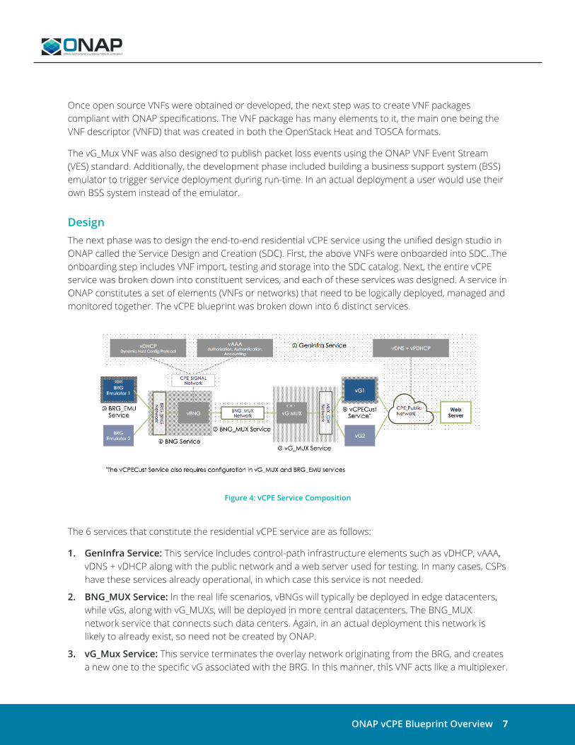
DesignThe next phase was to design the end-to-end residential vCPE service using the unified design studio in ONAP called the Service Design and Creation (SDC). First, the above VNFs were onboarded into SDC. The onboarding step includes VNF import, testing and storage into the SDC catalog. Next, the entire vCPE service was broken down into constituent services, and each of these services was designed. A service in ONAP constitutes a set of elements (VNFs or networks) that need to be logically deployed, managed and monitored together. The vCPE blueprint was broken down into 6 distinct services.
Figure 4: vCPE Service Composition
The 6 services that constitute the residential vCPE service are as follows:
1. GenInfra Service: This service includes control-path infrastructure elements such as vDHCP, vAAA, vDNS + vDHCP along with the public network and a web server used for testing. In many cases, CSPs have these services already operational, in which case this service is not needed.
2. BNG_MUX Service: In the real life scenarios, vBNGs will typically be deployed in edge datacenters, while vGs, along with vG_MUXs, will be deployed in more central datacenters. The BNG_MUX network service that connects such data centers. Again, in an actual deployment this network is likely to already exist, so need not be created by ONAP.
3. vG_Mux Service: This service terminates the overlay network originating from the BRG, and creates a new one to the specific vG associated with the BRG. In this manner, this VNF acts like a multiplexer.

ONAP vCPE Blueprint Overview 8
4. BNG Service: This service includes the BRG to Border Network Gateway (BNG) network and the BNG VNF. Often times, a CSP may already have this in place.
5. BRG_EMU Service: Since emulators were used instead of physical BRG boxes, this service deploys BRG emulators. A BRG emulator needs to be deployed per customer. In an actual deployment, a CSP would instead use physical BRGs.
6. vCPECust Service: This service consists of a distinct vG VNF per customer, and also includes IP address and VxLAN configuration in the BRG emulator as well as networking tunnel cross-connect configuration in the vG_Mux service.
In addition to network services, the SDC also allow designers to onboard additional artifacts and create recipes or management actions. The vCPE blueprint defines a closed loop automation recipe that consists of a policy to detect packet loss events from the vG_Mux VNF and based on a threshold, trigger a restart action for the VM hosting the VNF. Custom workflows were defined as well. ONAP comes with default workflows such as Create Service Instance, but requires custom workflows for operations such as BRG network configuration in step 6 above.
Finally, placement policies were created to ensure that VNFs are placed in the correct cloud/region. In this blueprint, two types of VNF placement policies were created. First, hardware platform awareness (HPA) parameters such as OVS-DPDK, CPU/NUMA pinning, hugepages and PCIe/SR-IOV pass-through and others are defined for datapath VNFs (vBNG, vG_Mux, and vG) to ensure they are placed on the right hardware. HPA uses a policy driven approach with Heat VNF descriptors and a model driven approach with TOSCA VNF descriptors. In other words, a Heat VNFD needs to be supplemented with policies while a TOSCA VNFD can describe HP requirements as part of the descriptor. Policies such as location and capacity are defined for correct VNF placement as well.
DistributionOnce the design phase is complete, various artifacts (service definitions, workflows, policies, analytic applications, VNF descriptors etc.) are distributed to the appropriate ONAP run time software component. This distribution is automatic, independent of the vCPE blueprint, and does not require any user intervention.
Run-TimeNext is the run-time phase. For the vCPE blueprint, the main run-time ONAP software components utilized are the Service Orchestrator (SO), related controllers (SDN-C for layer 2-3, APP-C for Layer 4-7 deployment and configuration and VF-C for VNFs with TOSCA descriptors), Active and Available Inventory (A&AI), and Data Collection Analytics and Events engine (DCAE). Of course, most of the platform’s other components are also involved in this blueprint as part of the standard run-time execution process, but a full discussion is outside the scope of this document.
To make the system ready to receive customer requests for service, the 5 infrastructure services (services 1-5 above) are first instantiated. Placement policies are adhered to by the ONAP Optimization Framework Homing Service (OOF-HAS) to ensure that VNFs are placed in the correct cloud/region. Next,

ONAP vCPE Blueprint Overview 9
the BSS emulator is used to trigger vCPECust service deployment in addition to providing run-time configuration. The end-to-end service is then demonstrated using a web client connected to the LAN side of BRG and a sink web server on the “public” network.
During run-time, a user may request an in-place upgrade of the vG VNF through the Virtual Infrastructure Deployment (VID) interface which triggers SO. SO automatically orchestrates an in-place software upgrade workflow, which initiates a sequence of steps such as VNF lock, pre-check, software upgrade, post-check and unlock. Since vG is an L3 VNF, the specific operations are carried out by the SDN-C controller in terms of running the pre-check, post-check and upgrade through Ansible playbooks.
Closed Loop At any time thereafter a command can be issued to vG_MUX to start reporting non-zero packets loss. The DCAE VES collector associated with the vG_Mux VNF getting this information generates a packet loss event. The analytics app applies the above-mentioned policy to that event, and once the packet loss exceeds a threshold, a vG_Mux restart action is triggered. The event is cleared once the packet loss goes below the threshold, which happens once the vG_MUX comes up again and starts reporting zero packet loss.
ResultsEarly results validate the benefit of the residential vCPE blueprint. New services can indeed be deployed in a matter of minutes, demonstrating the agility of the NERG architecture. 5 test cases have been applied to this blueprint, that include the test suite to validate the real-time, closed-loop automation described above. Finally, this entire blueprint is available to CSPs using 100% open source software.
SummaryThe recent NERG architecture allows services and network functions to move from a residential gateway onto the edge/cloud. By doing so CSPs can provide new services rapidly and on-demand to their residential customers. With a large number of new services expected in the near future, the residential vCPE blueprint demonstrates how CSPs can take advantage of ONAP to create new revenue streams and counter OTT competitors.

ONAP vCPE Blueprint Overview 10
TR-317 NERG specificationvDHCPvAAA VNF
vDNSvCPE use case wiki pageWatch the Technical Walkthrough video
Resources