one - aisc · pdf fileour product line includes a325, a 490 and aj07 structural bolts and a563...
TRANSCRIPT

~~ _ 0:3 0 Pa",ela Brent Secretary A~erican lnst . of Steel Constn One [ast Wacker Drive U 100 Chicago , IL 60S01-2001

UNITED STEEL DECK, INC. DECK DESIG~~~; SHEET
MAXIMUM FLOOR DECK CANTILEVERS
ADJACENT
SPAN
BEARING WIDTH
~
FOR UNITED STEEL DECK, INC.
CANTILEVER SPAN
SLAB
DEPTH
NOTES: 1.1 ALLOWABLE BENDING STRESS OF 20 KSI WITH LOADING
OF CONCRETE + DECK + 20 PSF OR CONCRETE + DECK + 150 LB. CONCENTRATED LOAD, WHICHEVER IS WORSE.
2.1 ALLOWABLE DEFLECTION OF FREE EDGE (BASED ON FIXED END CANTILEVERI OF 11120 OF CANTILEVER SPAN UNDER LOADING OF CONCRETE + DECK.
3.) BE.ARING WIDTH OF 3'12 ' ASSUMED FOR WEB CRIPPLING CHECK - CONCRETE + DECK + 20 PSF OVER CANTILEVER AND ADJACENT SPAN: IF WIDTH IS LESS THAN 3V,'; CHECK WITH SUMMIT, NEW JERSEY OFFICE.
4.) CALL NICHOLAS J. BOURAS, INC. ANYTIME YOU NEED DECK INFORMATION.
~"-\.\:'-"-I)J---j'~L.::::ff1~LJ NICHOLAS J. BOURAS, INC.
•
SPEED AND ACCURACY DOWN TO
THE LAST DETAIL. FabriCAD 11 from Structural Software. ItJr fa",cr. more accurate delailing. dra" on fubriCAD II. 1t ',lhe detailing program Ihat reneet; the actual problems )00 face in e-.ery job - and ;ohc; them.
Entering infonmation i; .imple. bt.'CaU5e input follows the erection plan. Based on the [·plon. fubriCAD 11 nol onl) accuratd) complele:. dctaib. it .1100 , for a wide variety of shop and field conneetion •. It also generates anchor bolt plan •. E·plans. bracing delail, and ck,ation ,iell',. And because all dimension; and connections can be ea.il) edited. change orders are a breeze.
Ii!aIUrc:. like till.'S< m.:an the end of long wait> for ,hop dr3\\ing,. \\1th fubriCAD 11. you can complete IWO or three time; 3> man) ,hcet, per day using the same personnel. And because all our programs are designed for IB\\ computers and compatibles. no ;pecial training is neec; .. ".
Call or "rite loda) for more infomlation on fubriCAD 11 and ulher Slruclural Soflware program •. induding: • EslinJating- Generates more accurate esllnJat!!> for hil!herprofi t mar¢ll> . • Imenton Control. ProdUction Conlrol and Pun:ha:,e Drders- Matcrial A1localion' programs lhal link pun;h",ing wi lh production 10 CUI "",Ie and boosl profits .
II~ are all ulIIllOri,ed melfer of floI'elf \ elllare alld [mex compulers. Structural Software Company. jOl2 Plantation Road, P.O. Bo\ 19220, Roanoke. STRUCTURAL SOnWARE CO, VA 24019. (800) 776·9118 SOFTW' . ' '01 THE sTU < IN D,

MODERN STEEL CONSTRUCTION
Volume 31, Number 6 June 1991 ------------------------------- ---
Memphis' "ewesl arena ;s a 450' -square, 290' -tall pyramid with a 52 ' angle of j"cli"nt iotl . The "nusual sltape required careful analysis mId c01lslrrtcl io1l planning. Tht story behi"d this wondrous structure begi"s on page 28.
4 1 Modern Steel Construction I June 1991
FEATURES 17 CONTROLLING FLOOR MOVEMENT
Serviceabilily problems can be controlled by the proper ellgilleerillg of damping alld the freqllellcy of structllralmembers
21 REDUcrNG AIRPORT CONGESTION A lIew steel e1t!vated roadway system at New York's /FK illtematiollal Airport is expected to ease access for its allllllal Crlmel, of 30 millioll passengers
28 THE GREAT AMERlCAN PYRAMID A lIew pyramid is risillg in Memphis-bllt on tire ballks of the Mississippi River illstead of the Nile River
35 VERTICAL EXPANSION OF VINTAGE BUILDINGS An IIl1derstallding of tire design practices employed ill the past call greatly simplify a rellovatioll project
38 VERTICAL EXPANSION TO ADD 235,000 SQ. FT. The lise of the lightest possible floor system ellabled the ellgilleer to add 20 stories and 235,000 sq. ft. to a villtage bllilding
40 PRESERVING CLEVELAND'S HISTORY The illterior of this landmark was completely rebuilt abave the secolld floor to create modem office space
46 BRlDGE EXPANSION HANDLES ADDITIONAL TRAFFIC A beautiful steel bridge was economically strengthelled alld modified to hmldle heavier loads on a wider alld safer roadway
NEWS AND DEPARTMENTS 6 EDITORIAL 10 Correspondence
9 STEEL NEWS • Alternate Bridge
Construction • Deeper Domestically • Electronk Data Transfer
Produced Wide Flange • Delta Airlines Section
• LRFD Book Review 50 AD INDEX
•
•
•

•
•
•
HlSlaR® A new generation
of rolled baame and column shapes
for economical steel construction.
Once aga in, ARBED leads ltIe Industry by featuring a trendsetting combInation 01 mechanical . chemical and technological prOpert ies
Inc.
DrIfOVATORI GrIDlLClaii,aUCTIOlJ PRODUCTS.
• HIGH YIELD STRENGTHS lup 10 65 KSI) • even tOt' ultra·heavy sections
• OUTSTANDING TOUGHNESS PROPERTIES
• EXTREMelY LOW CARBON EOUIVALENT - ensures excel· lent weidablllly
A NEW PROCESS .•• OST.
The secrel Is In ARB EO's revolu tionary new In-line CST process
OTHER RECENT ARBED INNOVATIONS:
" RBED-ROLLED oW·, 4,,·, and "TAILOR·MADE" (WTM) series -famoua tor high aecllon moduli, Or.a. 'aleral buckling reSistance, and tHO saVlnOs 'n fabrication coets Md wetghts These products .fe also available In the new HISTAR quality I. Is our standard WF sene, and H BEARING PILES
NEW LITERATURE AVAILABLE
Send now for comple,e data on all these "RBED produc ts, contact Trade ARBED, INC .. 825 Tturd Ave , New York, NY 10022. (212) 486-9890, FAX 2'2·355-2'5912' 2' In Canada' TradeARBED Canada, Inc., 3340 Me.lnwe." , BUflington, Onlario, Canada L7M lA7 1.,61335·57'0, FAX "6-335- '292

Editorial Staff Scott Melnick,
Editor Patrick M. Newman, P.E.,
Senior Technical Advisor Cynthia J. lahn,
Senior Technical Advisor
Editorial Offices Modem Steel Construction One East Wacker Dr. SUIte 3100 Chicago, IL 60601-2001 (312) 670-5407
Advertising Sales Eric K. Nieman, Patlis-3M Ed Sreniawski, Pattis-3M 7161 North Cicero Lincolnwood, IL 60646 (708) 679-ll00 FAX (708) 679-5926
AISC Officers Ralph H. Clarbour,
Chairman Stephen E. Egger,
First Vice Chairman Frank B. Wylie Ill,
Second Vice Chairman Oscar W. Stewart, Jr.,
Treasurer eil W. Zundel, President
David Ratterman, Secretary & General Counsel
Lewis Brunner, Vice President, Membershi p Services
Ceerhard Haaijer, Vice President, Technology & Research
Morris Caminer, Vice President, Finance/ Administration
6 / Modern Steel Construction I June 1991
EDITORIAL
Green Steel L ately, everywhere I turn J notice demolition activity. Driving
on Chicago's south side I see old Comiskey Park being torn down; during a presentation last week on the Lorna Prieta
earthquake, I saw the remains of the Nimitz Freeway; and on a recent trip to Detroit J couldn't help but notice several buildings being torn down.
The sight of a wrecking ball is at once awe inspiring and heart wrenching. Regardless of how progress-oriented we are as a society, most people still have a soft spot in their heart for the past.
But nostalgia aside, there's another reason to worry about the destruction of old buildings: The Environment. Today we need to worry not only about preserving the past, but also ensuring the future. And in this day and age of rapidly filling landfills, owners are faced with the problem of what to do with old building debris.
The problem is especially acute with a concrete structure. Concrete columns, beams and girders cannot be reused for much of anything except landfill-and as we're all away by now, that's one thing of which we don't need any more. (How much space does the destruction debris of a 1 Y4-mile long elevated roadway such as the Nimitz Freeway filI?)
In contrast, when an owner takes down a steel structure, the structural steel members can be recycled- melted down and reformed into new members for use on future projects (there was even a case a few years ago of a steel parking structure being dismantled and erected on a different site). And in addition to the ecological benefits of reducing waste, recycling saves money. The cost of the demolition contract is reduced by the value of the steel scrap.
Still another advantage i that steel structures often don't have to be demolished at all. If an owner needs a larger building, steel structures can often be easily expanded, in which case the demolition waste production is kept to an absolute minimum. Likewise, if a bridge needs to be modified to accommodate increased traffic, steel is the ideal material.
So the next time your kid or a neighbor asks what you've done lately to help the environment, tell them you designed a steel
•
•
structure.S~ •

Before We Ship Our Structural Bolts And Nuts, They Have To Earn Their Stripes.
When bolts and nuts rome from Nuror Fastener, you can have absolute ronfidence in their performance. That's because they're American made - and made ro meet the roughest standards.
fur starters, all the steel used in our structural bolts and nuts romes from Nuror Steel and other domestic steel mills. Plus, \ve provide raw material origin on all our certifications, and \ve
• can su pply original steel certification for traceability requirements.
Our product line includes A325, A 490 and AJ07 structural bolts and A563 grade C and heat treated grade
DH structural nuts. And \....eve recendy added mechanically galvanized strucrural nuts, bolts and washers along with ASTM Type 3 rorrosion resistant! \veathering products.
Our fully equipped laborarory lets us meet all ASTM quaLty standards. We provide proof tests and wedge tensile tests for all structural bolt products. And \ve can full-size tensile test our entire product size range instead of using machined samples.
What's more, \ve can meet special federal and state highway testing and certification requirements including
rotational capacity testing. All our fasteners are identified with
a lor number on each rontainer which allows traceability ro materials, dimensions, processing and testing.
And because we maintain a 7,0CfJron invenrory of fasteners we can always supply what you need. So call us at 8001955-6826, FAX 219/ 337-5394 or write us at PO Box 6100, St Joe, IN 46785 for more information. And give us the chance ro earn your business.
~ (j{J:fj\jI3 .13 .{


t;;:> ,;p I..)
,0 STEEL NEWS ,p
• Introducing A Deeper Domestic I-Seam
•
•
A 40"-deep, structural wideflange I-beam is now avail
able from Bethlehem Steel Corp. The W40 structural beam, which is used primarily for short-span steel bridges, is the deepest domestically-produced wide-flange shape.
The company's first 40"-beam had 12"-wide flanges and weighed 167 Ibs. per ft. Currently, Bethlehem is concentrating on the lighter weight sections (149, 167, 183, and 211 Ibs. per ft. of length). Sections will be available in ASTM Grades A36, A572-SO, and A588 Grade B.
"For now, we're going to concentrate on the lighter section weights, and once we get that accomplished we'll work in the heavier sections," said Andrew R. Futchko, manager of operations at
Bethlehem's Structural Products Division.
Deeper rolled shapes are important to various segments of the construction industry. The alternative is steel plates welded to form a beam of the appropriate size and strength.
"The availability of W40s will accelerate our structural customers' ability to accomplish construction work in more cost-effective ways," explained Jeff Manty, a Bethlehem mill superintendent. The availability of W40 beams will primarily affect the construction of short-span bridges.
"A bridge fabricator, for example, could save considerable time and expense by not having to fabricate built-up sections from three
Book Review:
separate pieces of steel," explained Robert E. Roll, Bethlehem's manager of the Structural Products Division's sales and marketing group. "Read ily available rolled W40 beams would eliminate those higher costs and related shop fabrication times in many cases."
Another LRFD Text Makes The Scene By Robert F. Lorenz
A new LRFD textbook covering Load and Resistance Factor
Design is now available for your technical bookshelf. "Structural Steel Design- LRFD Approach" was written by J.e. Smith, a professor of civil engineering at North Carolina State University. While much of the text serves as a primer, the author does introduce several innovative concepts.
The author's thrust is basically student-oriented. The text offers reminders and tips to the reader about various assumptions that are made, particularly in the approach to problems. While this may be a distraction to the more experienced practitioner, it no doubt serves less experienced readers well.
A close reading of the text does reveal some innovative solutions to problems, however. I would particularly recommend the chapter on bracing where the author thoughtfully blends the AlSC limits for out-
of-plumb and initial crookedness of compression members into a variety of bracing stability models.
Another innovation is the use of a novel lower bound treatment to inelastic column buckling problems, which is usually ignored in design practice.
The book's layout features very helpful decimal chapter divisions, which greatly eases a reader trying to locate specific topics. The book features 106 design examples and 198 problems distributed through its 11 chapters. One notable omission, though, is the use of photographs of steel structures that could serve to remind the reader what their designs should finally look like. Fortunately, Smith does make lip for this to some extent with bold, eye-catching figures and sketches. Still, many traditionalists will miss photos, especially those of monumental structures such as the Golden Gate Bridge and the SI. Louis Arch .
Since LRFD is relatively new, this treatise has a pioneering characteristic as it plows the virgin fi elds of LFRD utilization. [ would recommend this book for some of the unique approaches to problemsolving. Also, some readers will particularly like the author's treatment of braced and unbraced frames.
Although experienced designers may prefer a more tightly written text, the abundance of explanatory material aimed at students shouldn't stop anyone from sea rching the book for the large number of new techniques described in its 570 pages.
To order the $57.95 book, ca ll either John Wiley & Sons, Inc., at (201) 469-4400 or AISC Publications at (312) 670-2400 extension 433.
Robert F. Lorellz is director of educatioll "lid trainil1g for the Americall Ins/itllte of Steel COllstrllctioll, lire.
Modern Steel Construction I June 1991 19

CORRE~NDENCE __ __
Dear Editor:
T he March 1991 article tiUed "Bidding Alternate Design
For Bridge Construction" by Robert j . Desjardins (page 17) pointed out issues that we in Florida have been dealing with for some time.
Florida has been involved with segmental bridge design and construction for many years. No doubt some of Mr. Des~1Tdins' experience relates to some of our bridges, however, we have seen similar problems regardless of bridge type. For example:
1. Evaluating Alternates Through Cost.
We have long been a proponent of including costs such as design, design review, CEI, shop drawings reviews, and life cycle in evaluating alternates. However, isolating costs attributable to potential cost overruns due to delays and claims may be very difficult. One prob-
lem is in isolating the cause to specific design issues attributable to a bridge type. These costs seem to occur regardless of the bridge type although, as the article points out, they many be more prevalent with one type than with others.
2. Evaluating Alternate Through Design.
Trying to compare alternate designs is a difficult task under the best conditions. Whether or not the work is done by the same designer or by various designers, maintaining an objective view is difficult and is compounded by introducing different materials.
To address this problem, the FOOT developed the Bridge Development Report (BDR) phase. BaSically this has traditionally been "conceptual study", "type, size, and location" phase, but taken to a more comprehensive level. Within the BDR's framework, we thoroughly explore all viable alternates
Structural Material Sorter Ver. 3.0
A series of programs
designed to help
steel fabricators
manage material.
~_.:.:: :....l. ;:3;
: ;; .... --~ _"::J::f
• Reduce. labor - InCNases accuracy. • Automatically computes weightl, surface
area., bolt counta and linea' totals. • Quickly lort, liltl into proper order. • Produce. optimum length-cutting lilts from
in-house .tock, vendo,', stock or the b.,. combination of •• ch.
• Provide. shipping lIatl based on piecemark lequenee.
• Talliel material COltl, Ihop houri and ' ield houri 'or ea.y e.timating.
• Use • • Impli'ied tenn. so non-tech perl onnel can operate with ease.
• Externa' Data Interface can Import exi.ting computer-based material liltl .
• Call today 'or a FREE demo kit, Including the 'ull ,y.tem', operator', manual!
E.J .E. IND USTRI ES . INC.
COMPUTER SOFTWARE FOR STEEL PROFESSIONALS
287 Dewey Avenue Washington. PA 15301 (412) 228·8841
10 ' Modern Steel Construction I June 1991
aUowing us to make a reasonable comparison and a rational selection of alternates. The BDR looks at economical span lengths vs. superstructure types; comparative substructure types (piles, drilled shafts, etc.); aesthetics; life cycle costs and other major issues impacting final design. The end result is a document clearly defining all major issues and the rationale of each decision. Once approved by all the parties involved , both at District, State, and FHWA level, the document establishes the scope of the final design phase of the project.
As expected, the BDR's usefulness is directly proportional to the project's importance. When used properly, all parties are forced to make major decisions early, a comprehensive design scope of services can be written, the designer can schedule his work efficiently, and we are able to control the de-
IT IS FUN TO
DESIGN STEEL CON NECTI ONS
USING
DES CON
•
• AN EASY TO USE SOFIWARE PACKAGE
FOR YOUR PC
25 TYPES OF BEAM TO COLUMN CONNECTIONS. BEAM SPLICES AND
BEAM TO GIRDER CONNECTIONS
MOMENT CONNECTIONS SHEAR CONNECTIONS BOLTED AND WELDED
EXTENSIVE DATA BASE OF SHAPES, MATERIAL PROPERTIES AND
SPECIFICATION REQUIREMENTS INCLUDED
FOR INFORMATION CALL OR WRITE TO:
OMNITECH ASSOCIATES P.O. 80X 7511
BERKElEY. CA i4707 415-6sa-.328 I •

•
•
velopment of the alternates thus assuring as equitable a competition as possible.
3. Eval uating Alternate Th rough Reviews.
The other means of achieving equitable alternates is through proper reviews of the design plans. This, however, requires time and experienced personnel. There is a com.mon truism that the more expensive and critical the project, the less time there is to design it and schedules, or the need to meet preset submittal dates, becomes a Significant driving force. As a result, reviewers are often pressured to finish as quickly as possible. For states fortunate enough to have either a highly centralized operation and / or that do a significant proportion of their own design, the problem may not be so acute. In Rorida, however where we have both a semi-<iecentraJized operation and do about 90% consultant
bridge design, reviews become a sensitive issue. The consultant is driven by a need to meet the submittal dates (that's how he'll be graded and paid) thus the plans submitted may not be as complete as required and the reviewer is put on the spot.
Another argument used to reduce review time is that the savings due to the efficient design are often less than the expense caused by delaying the letting (i.e., cost of money, increased user costs, etc.). The argument is often posed in the form: What will the more efficient design save vs. what will the delay cost? In effect, the reviewer is asked to weigh structural efficiency for project expediency.
Manpower, another component of the review equation, may also be limited both in number and experience. The Rorida OOT is fortunate in having a highly experienced structures staff that can review and
design almost every type of structure type we have. Our problem is that there is always a manpower shortage with the potential of further red uetions. I n fact, the most common scenario is: reduce manpower, increase duties, and demand faster results.
4. Oesign Competitions. Two possibilities are "de
sign/build" and "design competition". In Florida, we recently built a bridge under the design / build concept with variable results. The primary criticism is that a consultant cannot afford the expense of doing the design at the risk of not getting the job. The contractor, on the other hand, may have the financial backing but still sees little reason to take the risk. A compromise may be to pay the design/build teams a nominal amount that wi1l cover some of the expense.
As with the design / build issues,
A325. A490 "RAPID TENSION" BOLTS
• Rapid Tension structural bolts from NSS have the lot identification number stamped on the head for complete traceability. American made. Rapid Tension bolts meet the highest industry standards and are the best bolts you can buy. Use your head - Insist on Rapid Tension structural bolts from NSS.
Nil 9077 GENERAL DRIVE· PLYMOUTH. MI48170
313-459 .. 9500 • 800-221-5126 . FAX 313-459-4830
Modern Steel onstruction I June 1991 111

a true design competition incurs costs that can be prohibitive and some mechanism to offset such costs must be used to attract truly qualified and capable competitors. Design competitions have be used recently in Maryland and Washington, DC. We explored the possibility in Aorida with a large bridge project in Jacksonville but found that state statutes do not permit this kind of competition.
5. Constructibility Reviews. We wholeheartedly agree with
this effort and have tried this process on several projects but found several impediments. First is the time restraint mentioned earlier. if done in-house, we can control and adjust schedules accordingly. If we go outside to either an individual contractor or to the contracting industry, we have little control on time. Secondly, going to a contractor introduces the problem of allowing a few contractors the opportunity to see a bridge project before other qualified and interested contractors. The second problem needs to be addressed by industry organizations.
In conclusion, the issues pointed out are valid and certainly need to be looked at closely. From our perspective, however, there are two additional issues. First, the amount of review time by both the designer (consu ltant) and the reviewer needs to be given as much importance as the design itself. Secondly, the very nature of our litigious society creates a highly defensive attitude in all participants.
We may not be able to do much about the second, but we should be able to do something about all the other issues.
Antonio M. Garcia, P.E. Chief Structures Engineer Florida Department of Transportation
Dear Editor:
I read with great interest the article in your January issue regard
ing the electronic transfer of data between the engineer and the fabri-
12 1 Modern Steel Construction I June 1991
CORRESPONDENCE,,--_
cator (page 53). This subject is one which is near and dear to my heart since I have devoted my career to creating solutions to these problems. However, in my humble opinion, although your facts were correct, your conclusions ignore important possibilities which are or soon will be available to us.
Over the last decades, responsibility for accurate design has shi fted more and more from the
Such a trend is unhealthy, costly, and irresponsible
engineer to the fabricator and detailer. Engineers have chosen to accept less responsibility for their designs, leaving more details to be worked out by the fabricator.
Ultimately, this trend will lead to engineers who simply draw a conceptual drawing of what a building or plant is to look like and leave it entirely up to the fabricator to design and build. Such a trend is unhealthy, costly, and irresponsible.
As a result, great expense is involved in bidding a project, since the fabricator must conceptualize substantial portions of the project in order to formulate a safe bid. The less detailed the bid documents, the greater the "fudge factor" which must be built in to COver unforeseen circumstance. Since for every successful bidder there are several who are unsuccessful, the overall cost of the estimating process is higher than it should be. The customer ultimately picks up the tab for a lot of Ulll1ecessary overhead.
A better approach would be for the engineer to completely design the structure, including all details. He should provide the fabricators with bid documents including an electronic bill of materials. The fabricator would apply his labor and material costs using computerized
estimating tools. The result would be that all bidders are comparing "apples to apples" with greatly reduced risk of omissions. Design responsibility would return to the engineer, who is getting paid to design the bloody thing in the first place.
This reversal of the trend will be implemented by improved technology. Companies like Steelcad International are nearly ready to deliver products which allow the engineer to "stick frame" a building and then turn that into detailed shop drawings electronically. Steelcad and other design programs are or can be smoothly integrated to production control software, like ou r Fab/ Trol System.
The engineer will conceptualize the structure, automatically creating a detailed Bill of Materials which can be electronica lly transferred to software like ours for creation of estimates, purchase orders, cut lists, inventory reduction, production control and bills of lading. Responsibility is properly assigned to the parties best prepared to accept it. The ultimate recipient will be the customer.
Douglas Cochrane Director of Development Fabrrrol Systems, Inc. Eugene, OR
Dear Editor:
We appreciate the fine article on the Delta Airlines Or
lando Aight Center (page 12) in the April 1991 ed ition of Modern Sleel COllslrucliO/I. The layout use of photographs was done extremely well and portrays the building in its true light.
However, one misconception occurred in the text. ACI / Mitchell was the general contractor for the steel construction package but Great Southwest Corp. was the general contractor for the architectural and the MEr package.
Michael C. Head, P.E. O'Kon & Company Atlanta
. ,
•
•
•

" ·~ l\~'
Ii ~ .. ~ r\ " t,~ I,. : ~ ;' '. I.·. ,
\ I:. • !,"\'
".L \1'" I/1W
~ ~
" ~
I ~ (: t\ IV
~ IY' 1\.- 1),= 1-"0

Why is Bethlehem's \\ in the Inverse!
Heres the long a
Ik:thlchcm's "C31hcring MCci anu (he innU\ all\ C 1m Cf"iC[
bridge Ii~ ~lcm afC a perfect fit. !mcrset offers engineer') an economit'al solution for a wide
\-:!fiery of bridge rt."<luircrnems- " hcdlcr for long-~p~lI1 . short-span, nc\\ construction or bridg,c rcpla('cmcm projects.
And ,hat's importan!. Becausc, according 10 I'll\\:>\ c'>rim3rcs. of some SHO.OOO brid~c'i in [he coum~. 0\ er ·-10°0 afe \tructurally deficient or functionJlI~ obsolete.
The Imerser bridge '~~[cm. manufactured in the !OrthC3St
by ' 111C Fort MillcrCompan~. uses upside do\\ n deck casting [(..'Chniquc~ co prO\ ide :l high-quali~. prc"omprcsscu concrete deck on lightweight prestressed steel stringers. This rC~lIl(s in an economical unit rcad) for field placemclU. Additional savings arc ~:Iincd through rapid crcction
:Inu minimulll oUl-of-scn i<..·c time. The.: nwoulc"t C;11l he platcd eithcr longituuinall~ or trans\(,:r..,el~. Their ligIH-\\cight dcsign characteri'Hics make Imcr,cl the ide:!1 !'OIUlioll \\ here dead load is n con\traim.
\Vh~ \\e3thcring ,tcel?
' nll: usc of high-<.,trength AST~1 ASKH \\ t.:Jthcring "ttcel bcalll' add, to the 0\ crall t.:(·()nom~ -bOth int[iJII~ Jnd dO\\ n the road.
Compared to ordina~ ASTM A36 steel, \\c;tthcring ..,tcd\ 3Ho,o higher ~ield ",trcngth pt.:rmits structures to ha\c lighter. slimmer scctions. And "incc \\('''3lhcring Slcd rc"tj't . corrosion. painting is rarel~ requirt.:d. In adoition. \\cathering s[cd"" rich. brO\\ n o\idc coaling blcmh \\ ith thc cmironmcnt \\ ilhollt di'iIllrbing it.

,n
ciatherin steel used ftri~ ystem?
the short of it.
Iklhlchcm\ \\ cJlhcring \(cel \\ .1, rct'cllll~ u'\ed b~ ' 111c Fon \ lillcr ( :0. in [\\0 UP..,IJtc '\c\\ ' cuk project.:; . "Illc Rock" ell Falb Bridge rehabilltJtion pn,JCct (or the Ilutj..,on Ri\cr Bndge a( Lake LU/crnc. ~" r<..."tlulred JUlil 1M day., of do\\ mime. The units. \\ hit h \\ erc po\ltioncd (rans\l;rsel~. rt.:placed the c:xisting noor beam .. Jnd dc<:k on the IMOo-fl .-long bridge.
' lllC CfCt.:[lon of the Outlet ROJd Bridge in SJ.ralO~ Coun~. \\J., complctcd in lulf J dJ\ , Three 9 00ft. 61/.o-in .-\, ide units \\Cfe u'ied longitudinJII~ on the 35-ft.-long structure .
The Fort \l iller Co. i\ ')old on the 3cstchtics and (0<;(-
•
1g benefit\ of \\ cJthcring \tccl. \\c think you 11 be. (()O .
o get a cop~ of our Product Booklet. No. 3 790 and our IatcSt ' )cchn icJI Bulletin. TB-307 on "l 'n<.:o:ucd \Veathering Steel Structure,". C.dl: (215) 694-5906.
Bethlehem Steel C:orporJtlon . C:un'ltruc..' tIOI1 \IJr"cul1g I)" ;,;on. Ikthlchem. P\ IHOI6. Rod''''ell Fall" HridRe: nefti 0", ne ... : SaralOla and Warren Counllec . 'itatto of \ e'" lork FabnulOr: Seibe l Modem .)tanu(actunnJt and \\ eldlng Co .• lancuter. S \ General ConlraclOr: J , H. ')lalo). loc .. Alb.n). \ \ Outlet Road 8ndKto: lriahll Owne ... : Saratoga Counl). Slate of l\e .. l ork F.bricalor: !W1bc:1 Moclcm Mlmuflll'lunnK and " ddlnll Co., 1..a11(:" ttor, ~\ General COnlra('lOr: Sl:hultl CUlIlItnKlion IIK' .• Round l..ake. "\ Co""ultinlit Eng'"et'r: Gr~nman· I· .. dt·r.cn In(' .. \tban) . ,,\ 1"\l'r,",1 Ucen~e: The Fori \filluCompu\, lnc., Schu)len,lIe. '1\ \\eathering Steel Supplier: Bethlehem Steel Corporation, Bethlehem, r\
Bethlehem~ (I"tj INVERSE'I' II I tradem~k .00 3Cr~1CC mlrk 01 KCllh .nd Gronml1l Le.,~ Co .. ' ormln. Oklahom.

S~lll/ISDS -Ranks #1 in Earthquake Engineering
A recent (October, 1990) ENRlMcGraw Hill survey of the Architecture/Engineering/Construction industry ranks ST AAD-IIIIISDS, from Research Engineers, as the # I structural engineering software today.
Whether it is a single beam or analysis of a 3D multistory structure for seismic response, ST AAD-Ili/ ISDS has been the engineer's # I choice - since 1978.
Today, Research Engineers, with six offices on four continents, is making the world's knowledge available to the industry - with continuous implementation of the latest technology.
State-of-the-art dynamic/earthquake engineering facilities include the world's fastest and most accurate eigensolution algorithm, response spectrum capabilities with SRSS and CQC modal combinations, numerically efficient plate finite element to model shear walls and rigid diaphragms, automatic generation ofUBC loading, statidanimated mode shape plots, direct combination of statiddynamic analysis results with fully integrated implementation of STEEUCONCRETEITIMBER Design based on American and ten other Foreign Codes.
ST AAD-IIIJISDS - #1 For a Reason,
,~ Research [ill] ~ .,., Engineers [IIIJ ~ -- . . Also introducing AutoSTAAD - structural draft ing, A reputation you can bUild on. ST AAD-III CIVILSOFT
model generation and STEEl/CONCRETE/TIMBER For Information call I-BOO-FOR-RESE detailing within AutaCAD. ISH- I N Batavia Street,O~nge,CA 92667
Phone: (71~) 974-2500 Fax: (714) 974 -~771
RESEARCH ENGINEERS W O RLDW IDE UK: R."u~h Efl, loeen (hrope) ltd~ 19 lanldowla Cou", Brl&h ton Roa.d, P"",,y SoiN"ey e M lBO Phone:: (081) 763- 1 ) 9) fax; (08 I) 76)· 1379 Telex 919181 FRANCE: R"uun;h En,lneel'S. 18 Ned" Mon:l~ illc.18800 FlACEY Phone: 17 '17 51 6} Fax: 37 -4 7 .. -4 6) CERHANY: P.elun:h Enl inHn, W itleIfn..8 u,d.·$(r. ]), 61 <40 BENSHEIM ) AUERBACH Phone: 0615 1 19577 fu;: 06151 H4)7 IN DIA: Reu ard. En. ineen P-tl. Ltd~ 408 0 , .... Rotd. Calell" . 700 01 7, Phone: .... 8 9 14 Telf:lc: 11 4 1 02
•
•
•

'D ,D tAl
,D NATI O NAL STEEL C O NST R UCT IO N C O NFERENCE w
•
•
•
Controlling Floor Movement
Serviceability problems can be controlled by the proper engineering of damping and the frequency of structural
members
Thomas M. Murray, Montaglle- Betts Professor of Structural Steel Design at Virgillla Polytechnic Institute, is the willll" of this year's Af5C T.R. Higgins Lectureship Award. Murray will present his paper at least seuell times ill 1991-92, OOg;"";118 at this year's National Steel Construetja1l Co,,{erenct ill Washington, DC. Cities where the paper will be presented include: Chicago; St. Louis; Klw sas City; Tuscon; Los Angeles; and Dallas . For more in/ormat ion, write: Robert Lore1lz, Director of Education . American Institute of Steel eo1lstructiotJ , /IIC., Olle East Wacker Dr., 5I1it<3100, Chicago, IL 60601-2001.
"AnnoYing floor motion induced by building occupants is probably the
most persistent floor serviceability problem encountered by designers," according to this year's AlSC T.R. Higgins Lectureship Award winner.
Thomas M. Murray, MontagueBetts Professor of Structural Steel Design at Virginia Polytechnic Institute and State UniverSity, will present his paper, Bllilding Floor Vibrations, at six venues this year, beginning at this year's National Steel Construction Conference. The paper presents an overview of analytical tools and concepts for controlling annoying floor movement in residential, office, commercial and gymnasium environments.
II A number of procedures have been developed by researchers that allow a structural designer to analytically determine occupant acceptability of a proposed floor system," Murray writes. "Generally, the analytical procedures require the calculation of the first natural frequency of the floor system and either maximum amplitude, velocity, or acceleration of a reference excitation. An estimate of the damping in the floor system also is required in some instances. A human perceptibility scale is then used to determine if the floor system meets serviceability requirements.
Residential And Office Design In residences and offices, vibra-
tions occur primarily as a result of either individuals or small groups walking across the floor. "As a result," Murray states, "the most important parameter for residential and office environments is damping."
In his paper, Murray states: "If the following inequality is satisfied , motion of the floor system caused by normal human activity in office or residential environments will not be objectionable to occupants: 0 62> 35 Ao( + 2.5 where o = damping in percent of critical, Ao = maximum initial amplitude of the floor system due to a heeldrop excitation (in.) and f = first natural frequency of the floor system (hz).
The heel-drop excitation used to develop the criterion can be approximated by a linear decreasing ramp function having a magnitude of 600 lbs. and a duration of 50 milliseconds.
''The criterion was developed using a field measurements of approximately 100 floor systems mostly in the frequency range of 5-8 hz," Murray said. "Use of the criterion for floor systems with a natural frequency above about 10 hz is not recommended."
Murray warns, however, that "Use of this criterion requires careful judgement on the part of the designer."
For example, while a typical office building floor system with hung ceiling and minimal mechanical ductwork exhibits about 3% of
Modern Steel Construction 1 June 1991 / 17

NATIONAL STEEL C O NST R UCTION CON FE R ENCE
spacing or the effective floor width that is used to calculate system amplitude, Murray said.
When partitions are not used, an inexpensive method of artificially increasing the damping is to install "false" sheetrock partitions of maximum depth in the space between
those below about 3 hz and those between 5-8 hz. In more than 50 floor problems investigated by Murray, the problem has been where the measured first natural frequency of the floor system is between 5 and 8 hz. Murray said he has never encountered a problem
critical damping, additional damping may be provided by office furniture, partitions, equipment and the occupants themselves. "If the required damping is less than 3-3.5%, the system will be satisfactory even if the supported areas are completely free of fixed partitions." However, when the required damping is between 3.5% and 4.5%, the fi nal configuration and its intended use must be carefully considered.
And if the required damping is much greater than 4.5%, the designer must either identify an
Framed-in-place partitions are I very effective sources of
damping when each partition is attached to the floor system in
at least three locations I
with floor spans greater than 40', which is contrary to the common belief that long span floor vibrate and shou ld be avoided. "Furthermore, an office/residential floor with a natural frequency greater than 10 hz has never been found to be a problem."
exact source of damping, provide additional damping, or redesign the space. Framed-in-place partitions are very effective sources of damping when each partition is attached to the floor system in at least three locations and they are located within the effective beam
the ceiling and the underside of the floor slab. Murray states that his tests have shown an increase in damping of 0.5% to 1 % using 2' - to 3'-deep false partitions.
Another floor vibration problem deals with frequencies, especially
Retail Design Because the forcing function in
retail settings is nearly continuous walking or running movement, damping is not as critical a concern as it is for office/residential environments. "Control of the stiffness
THIS IS WHAT IT TAKES TO BE A BOLT MANUFACTURER IN THE 19905:
~ "tLI
Type , T.".3
r::\ v::J . .,., .....
Registered Head Markings on all structural and machine bolts from SAo" to 3" diameter, all lengths
Special Products from '''" to 3" diameter
Iwedge .......
• u.s. made steel
• Wide-range manufacturing capabil ities
• Weathering steel : CORTEN X
• Guaranteed full traceability
• In-house lab testing
• Certification
ST. LOUIS SCREW & BOLT COMPANY SINCE 1887
'Nou,,"rn'IlL rc. D ,. ..... rlNI us Yi .. , .. ,.,It
L 0 'N~,.,rur~ .
6901 N. Broadway/SI. Louis, MO 63147/(314) 389·7500
FAX, (314) 389·7510 Toll Free, 1·800·237·7059
•

•
•
avoid resonance. of the structural system is the best solution," Murray states.
Murray cites Bruce Ellingwood, a professor at Johns Hopkins University and a former Higgins Award winner, who recommends a criterion based on an acceleration tolerance limit of 0.005 g and walking excitation. "This criterion is satisfied if the maximum denection under a 450 lbs. (2 kN) force applied anywhere on the noor system does not exceed 0.02 in.," Murray said.
Gymnasiums "For noor systems supporting
dancing or exercise activities, damping is usually not of consequence," according to Murray. Because the accompanying music for aerobic activity does not exceed 150 beats per minute, the resulting forcing frequency is only about 2.5 hz. However, the first natural frequency of noors supporting such activity should be above 7-9 hz to
To avoid floor-motion complaints, Murray recommends: providing structural framing so that the first natural frequency is generally above 9-10 hz; isolating the noor systems from the remaining structure using separate columns; separa ting ceilings and partitions immediately below the exercise floor by supporting the ceili ng o n its own framing and by not extending partitions to the noor above; and accepting the possibility of complaints from non-participating individuals who happen to be one the exercise noor during activi ty by medium to large groups (20 to 60 participants).
Murray's full paper, Bllildillg Floor Vibratiolls, will be printed in the Proceedillgs of the 1991 Nntiollal Steel COllstructioll COllferellce and in the Third Qllarter 1991 Iss lIe (available in September) of Ellgilleerillg JOllmnl."
Copies of the Proceedings can be obtained for $35 + tax + UPS shipping charges by contacting: Al , Publications Department, P.O. Box 806276, Chicago, IL 606804124. For phone orders, call (312) 670-2400 ext. 433.
Single issues of Ellgilleerillg jOllrIInl are available for $5 ($6 foreign) by writing to: AlSC, Ellgilleerillg jOllmnl, P.O. Box 806276, Chicago, lL 60680-4124. One year subscriptions are $15 ($18 foreign surface mail; $44 air mail) and a three year subscription is $36 ($45 foreign surface mail). a phone orders are accepted for Ellgilleerillg jOllmnl. 0
According to Murray, the least expensive method of obtaining structural framing with sufficient stiffness to meet the 9-10 hz cri terion is to use deep beams or joists and lightweight concrete slabs (a decrease in mass increases frequency) .
AISC SOFTWARE LRFD/ASD Computer Software Data Base For Structural Shapes
The AlSC Computer Data Base contains properties and dimensions of structural steel shapes corresponding to data published in Part I of the 1st Edition, LRFD Manual of Steel Construction as well as the 9th Edition, ASD Manual of Steel Construction.
The program includes the Computer Data Base in ASCII format for the.properties and dimensions of the following shapes: W Shapes; S Shapes; M Shapes; HP Shapes; American Standard Channels (C); Misce llaneous Channels (MC); Structural Tees cut from W, M and S Shapes (WT, MT, ST); Single & Double Angles; and Structural Tubing and Pipe.
Steel Member Fire Protection Computer Program
STEMFIRE determines safe and economic fire protection for steel beams, columns, and trusses. It is intended for use by architects, engineers, building code and fire officials, and others interested in steel building fire protection . The software data base contains all the pertment steel shapes and many li sted UL Fire Resistance Directory construction details and their fire ratings. ]0 this manner, user search lime is minimized and the design or checking of steel fire protection is optimized.
Steel Connection Design Software (CONXPRT)
CONXPRT is a knowledge-based PC sonware system for the des ign of stecl building connections. Three basic types of connections are included in Version 1.0: double framing angles; shear end-plates; and single-plate shear connections. More than 80 configurations are possible.
All designs are according to p'rocedures in the AlSC 9th Edition (ASD) or latest avaIlable references. CONXPRT includes complete data bases for standard shapes, the structural stee l, weld and bolt materials listed in the 9th Edition. All strenj!th and serviceability limit states and dimensional reqUlrements for each design are checked. Help menus are included.
WEBOPEN This state-of-the-art sonware package is based on and
includes the new AIS Design of Sleel and Composile Beams with Web Openings . The program is designed to enable engineers to quickly and economically design beam web openings. The easy-to-use color coded input windows provide a clear, logical data entry system.
WEBOPEN was written by practicing engineers and incorporates "expert" design checks and warning messages that enhance the application of the AlSC Design Guide to your design problem •.
The versatile system designs unreinforced or reinforced openings in steel beams, both composite and non·composite .
For more information, contact: AISC Software, One East Wacker Dr" Suite 3100, Chicago IL 60601-2001 (312) 670-5434.
Modern Steel Construction / June J99 J / 19

IN A RECESSION, THE BEST DEFENSE Is A GOOD OFFENSE.
I t's a recession. Your instincts demand that you cut the ad budget. But, as the McGraw-Hili Research' analysis of business-to-business advertising expenditures during the 1981-82 recession shows, it's those with the courage to maintain or increase advertising in a recession who reap a major sales advantage over their competitors who panic
Effects of Advertising in a Recession on Sa les and fall back into a defensive posture. And this advantage continues to expand long after the recession is over.
1980
(Indices) 375
Companies thai Maintained or Increased tldt>erlis;ng in Both /98 / and /982
Companies thaI Eliminated or Decreased tldl 1(!rtising in Both /98/ and /.982 195
159
89
1981 1982 1983
283
19M 1985
Recessions last an average of II months. but any advertising decision made during one can have permanent repercussions. The McGraw-Hili study demonstrates that nervous advertisers lose ground to the brave and can't gain it back. In 1980, according to the chart seen here. sales indices were identical, but by 1985 the brave had racked up a 3.2 to I sales advantage. A similar study done by McGraw-Hili during the 1974-75 recession corroborates the 1980's research.
A recession is the single greatest period in which to make short- and long-term gains. And, surprisingly, increasing advertising modestly during one has much the same effect on your
profits as cutting advertising does. According to The Center for Research & Development's October 1990 study of consumer advertising during a recession, advertisers who yield "to the natural inclination to cut spending in an effort to increase profits in a recession find that it doesn't work:" This study, relying on the PIMS' database, also uncovered that aggressive recessionary advertisers picked up 4.5 limes as much market share gain as their overcautious competitors. leaving them in a far belter position to exploit the inevitable recovery and expansion.
Chevrolet countered its competitors during the 1974-75 recession by aggressively beefing up its ad spending and attained a two percent market share increase. Today. two share points in the automotive industry are worth over $4 billion. Delta Airlines and Revlon also boosted ad spending in the 1974-75 recession and achieved similar results.
Continuous advertising sustains market leadership. And it's far easier to sustain momentum than it is to start it up again. Consider this list or market category leaders: Campbell's. Coca-Cola, Ivory, Kellogg, Kodak, Lipton and Wrigley. This is the leadership list for 1925. And 1990. These marketers have maintained a relentless commitment to their brands in both good times and bad. Kellogg had the guts to pump up its ad spending during the Great Depression and cemented a market leadership it has yet to relinquish.
These are the success stories. Space and diplomacy don't allow the mention of the names of those who lacked gusto and chose to cut their ad spending in recessionary times.
But if you would like to learn more about how advertising can help make the worst of limes the best or times, please write to Department C, American Association or Advertising Agencies, 666 Third Avenue. New York, New York 10017, enclosing a check for five dollars. You will receive a booklet covering the pertinent research done on all the U.S. recessions since 1923. Please allow 4 to 6 weeks for delivery. McGra .... ·lhll Rtse,uch. 1986 The Center for Rtstarch and ~'t' lopmtnt 0 1990 Profit Impact 01 ~I.arket Slr~ttg'tS, The Strategic l>tannlng lrutitute, Cambru.lge. MA.
•
•
•
•
•
NATIONAL STEEL CONSTRUCTION CONFERENCE
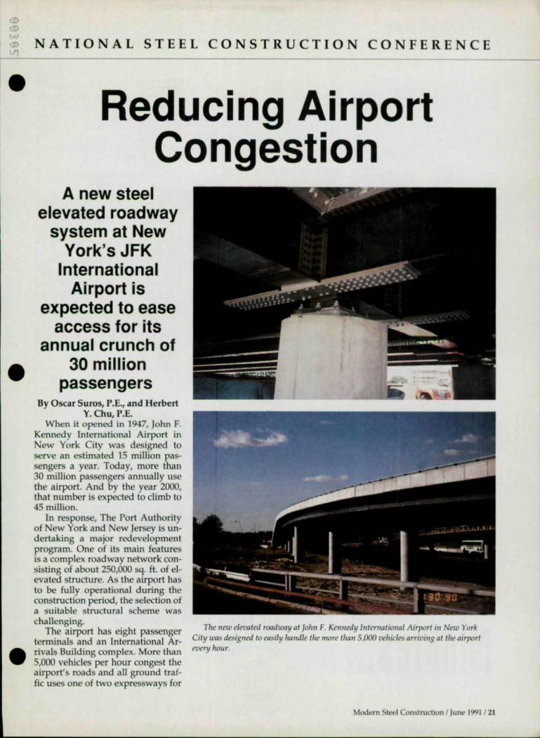
Reducing Airport Congestion
A new steel elevated roadway
system at New York's JFK
International Airport is
expected to ease access for its
annual crunch of 30 million
passengers By Oscar Suros, P.E., and Herbert
Y.Chu,P.E. When it opened in 1947, John F.
Kennedy International Airport in New York City was designed to serve an estimated 15 million passengers a year. Today, more than 30 million passengers annually use the airport. And by the year 2000, that number is expected to climb to 45 million.
In response, The Port Authority of New York and New Jersey is undertaking a major redevelopment program. One of its main features is a complex roadway network consisting of about 250,000 sq. ft. of elevated structure. As the airport has to be fully operational during the construction period, the selection of a su itable structural scheme was challenging.
The airport has eight passenger terminals and an International Arrivals Building complex. More than 5,000 vehicles per hour congest the airport's roads and all ground traffic uses one of two expressways for
The new elevated roadway at /olln F. Kennedy J"tematiotlal Airport i" New York City was designed to easily handle the more thall 5,000 vehicles arriving at Ihe airport every hOl4r .
Modern Steel Construction I June J99J / 21

NATIONAL STEEL C O NSTRUCTION CONFE R ENCE
..
In" st
entering or exiting the airport. Both inadequate passenger drop-off and pick-up points and circuitous routing of vehicles contribute to traffic problems.
The new roadways are designed to provide easier access to the Central Terminal Area, the airline terminals, and the International Arrivals Building.
Functional Requirements The major geometric features of
the roadway system include: • Straight alignment with variable
road wa y wid th and cu rved profile;
• Curved alignment with variable roadway width and curved profile superelevation;
• Transition areas (two roadways merging into one or one wide roadway splitting into two) with curved alignment and curved profile. The structural system selected
for this project not only had to ac-
commodate the above geometric requirements, but the deSigners also had to consider: structural flexibility; constructabiHty; aesthetics; maintenance; and bidder's competition. And, of course, the airport must remain fully operational during construction.
Alternative Structural Systems
Eight steel and concrete superstructure systems were evaluated. To establish a common base for evaluation, a single column pier for the substructure is assumed for all systems. • Simply Supported Welded Plate
Girders: Straight or curved simply supported steel welded plate girders on concea led steel box capgirdcr.
• Steel Rolled Beams: Straight or curved, simply supported or continuous steel rolled beams over cast-in-place concrete hammerhead pier.
we can fax a finished shop drawing to your
specifications, complete with paint notes & bolt count. ..
minutes ... call 1 · 800 · 458 · 7875
to find out how ... 200 E. ROBINSON
ORLANDO. FLORIDA 32801
•

.n
•
•
•
• Continuous Welded Plate Girders: Straight or curved continuous steel welded plate girders framed into concealed, steel I-shaped cap girders.
• Steel Box Girder: Straight or curved rectangular steel box girder over cast-in-place concrete hammerhead pier.
• Adjacent Precast Concrete Box Girders: Ad~lcent precast, prestressed concrete straight box girders supported on concealed, cast-in-place concrete hammerhead pier.
• Precast Concrete AASHTO 1-Beams: Precast, prestressed concrete AASHTO I-beams simply supported on cast-in-place concrete hammerhead pier.
• Concrete Segmental Box Girder: Simply supported or continuous precast concrete segmental box girder post-tensioned inside the box, over cast-in-place concrete hammerhead pier.
• Cast-In-Place Concrete T-Beams: Simply supported or continuous concrete T-beams, cast-in-place monolithically with the deck, over cast-in-place concrete hammerhead pier. An analysis of the eight systems
included structural f1exibiJjty, constructability, aesthetics, maintenance, and bidder's competition.
The analysis revealed that all of the concrete structural systems would require greatly reduced span lengths for curved alignment with small radii, which represented approximately 15% of the project. For some systems, cast-in-place construction would be required at transition and at sharply curved areas. As the cast-in-place construction would greatly interfere with airport operations, none of the concrete systems were suitable for this project.
Analysis revealed that the two most desirable systems, both in terms of aesthectics and cost, were both Welded Plate Girder systems. The advantages of both systems include: the ability to handle relatively long spans and curves with various radii; structural depth wellproportioned to corresponding
A co"tUlIIOUS welded plate girder system was chose" as wh'g the most desirable 111
terms of cost mId aesthetics, as well as IIaving wry low m"mten"nce requirements .
Mod{'rn Steel Construction 1 June 1991 / 23

NA T IONAL ST E EL CONSTRUCTION C ON FE RENCE
1
• ,
o
24 1 Modern Steel Cons tructio n I June 1991
span length; easy adaptation to the complex geometric requirements at roadway transitions; reduced on-site construction time since aU structural steel members are fabricated off-site; relatively simple erection procedure thereby reducing the impact on airport operations; aesthetically pleasing design; and easy repair or replacement of deteriorated deck slabs.
While both systems share the same major advantages, the Continuous Welded Plate Girder system reduces the total number of maintenance problems.
In addition, the simply supported system has a deeper structure for the same span length and requires a raised roadway profile to allow for the required clearance under the structure, thus increasing the total square footage of the elevated roadway structure and the cost of the project. Thus, the Continuous Welded Plate Girder system with steel I-shaped cap girder was selected.
Superstructure Design The alignment and profile of the
roadways are extremely complex due to the limited space and stringent operational restrictions at the airport. About 44% of the roadway structure is on tangent alignment and the remainder on curved alignment. The radii vary from 145' to 10,000' . The maximum cross slope is 6% and the profile has a maximum slope of 6%.
The typical deck structure is an Blt.!", cast-in-place concrete slab on stay-in-place steel forms. Since the elevated roadway is designed to accommodate vehicular traffic only, there is no sidewalk provided on the deck. To satisfy aesthetic requirements, the fascia plate girder stringer maintains a constant distance of 4' from the face of the deck structure whether it is on a tangent or a curved alignment.
A nominal depth of 3' was selected for aU stringers. Since the cap girder is required to be concealed within the depth of the
stringer, and because of geometry and detailing requirements, the depth of the I-shaped cap girders is less than 3' . All stringers frame into the cap girder, except at the expansion joint where stringers are supported on expansion bearings attached to brackets on one side of the cap girder.
Because the depth of the concealed cap girder is less than 3', the maximum width of structure for the single column system is limited to 34' .
For roadway widths exceeding 34', two concrete columns are required to support the C<1p girder and are placed at locations that do not interfere with other on-grade roadways or major underground utilities. In one instance, three concrete columns are used to support a very long steel cap girder.
To control the size of the deck expansion joint and temperature stresses in the overall structure, a maximum distance of 465' between deck expansion joints is used . Depending upon the location of columns allowed by the ongrade roadway geometry, the span length varies from 48' to 119', and the number of continuous spans varies from two to five.
For the design of the continuous stringers, the Line Girder System program from Bridge Software Development International Ltd . was used for the tangent stringers, and the V-Load Analysis program from United States Steel Corp. was used for all curved stringers.
A 16" and 24" flange width was selected for all stringers and cap girders, respectively, with varying flange thickness controUed by strength, fatigue and deflection requirements. All steel is A572 Grade SO, except for the diaphragms and diaphragm connection plates, which are A36 steel. AU field connections are made with 1 "-diameter high-strength bolts, except at the diaphragms where 718"-<liameter high-strength bolts are used .
Structural Details To improve aesthetics, the steel
cap girder was concealed to create
•
•
•

•
•
•
visual continuity of the fascia tor is required to shop assemble a~ stringer. As a result, at the expan- field connections for a full girder sion joint the expansion bearing for assembly from expansion joint to the fascia stringer had to be IUdden expansion joint. behind the fascia, which is only 3' As a result, any misalignment deep. This was accomplished by or other errors can be corrected using a shallow transfer beam con- prior to transporting the members necting the fascia and the first inte- to the site. Also, to eliminate some rior stringer. common geometry errors during
To allow temperature movement construction, the fabricator is reof the fascia stringer in the longitu- quired to survey in the shop the dinal direction, an expansion bear- location and orientation of center ing attached to the underside of the lines of all cap girders and center transfer beam and located 1'-9" lines of cap girder bearing during from the fascia the shop assem-stringer was I .. I blyoperation. provided. For Construction time was Based on air-the interior . d d f 35 port operational stringer, the ex- , revise own rom I requirements, pangion bearing months to 25 months J the project was is located at the divided into center line of the -- four phases, stringer. All expansion bearings are with approximately two thirds of low profile and seated on shallow the elevated structure in Phase I. brackets welded to the cap girder. By April, more than one half of the All other stringers are rigidly elevated roadway structures in bolted to the cap girder to create a Phase 1 were complete, and the continuous structure. contractor, Slattery Associates,
The connection between the steel Inc., Maspeth, NY, had revised the cap girder and the concrete column estimated construction time from in the single column system re- 35 months down to 25 months, suited in an uplift bearing with two and is expected to be completed parts: Each has two, 2:Y4"-<liameter by the end of 1991. uplift anchors to develop tension . . due to the moment effect and seven Reduced Construcllon Time 1 Vz"-<liameter anchor bolts to de- This Significant reduction in velop the transverse and longitudi- construction time is mainly attrii>nal shears. utable to the ease of steel erection
Shop-Welded Plates The sole plate has a curved sur
face at the bottom to allow the cap girder to roll slightly to accommodate the rotation of the connecting continuous stringers. The sole plate is shop-welded to the cap girder and keyed to the base plate by two, 2W' diameter pintels. Since the rotation of the cap girder is very slight, the uplift anchor connection to the cap girder is capable of accommodating this movement. For cap girders supported on multiple concrete columns, uplift anchors are not required and standard bearings are used .
To minimize field adjustments to the teel framing, the steel fabrica-
in the field and to the quick resolution of field problems between the contractor and the design engineers. The requirement of shop assembling all steel members between expansion joints was an important factor in avoiding field problems and speeding the erection. Steel fabricator for Phase I is Harris Structural Steel, Co., South Plainfield, NJ .
Oscar SlIras is chief structural ell gilleer alld Herbert Y. ehll is prillcipal '"gilleer of The Port Authority of New York alld New Jersey. This artiele was adapted from a paper he presellted at the Natiollal Steel COllstruCtioll COllfemlce ill \llhshillgtoll, DC. 0
ARKANSAS SAVES YOU
. TIME LABOR MONEY
WITH WF BEAM CUSTOM SERVICES:
CAMBERING
T .J..
TEE-SPlmING
DRILL & COPE
I END MILLING
CUT-To-LENGTH
STORAGE. TRANS-SHIP
A FW.sE!MCE stRUCTURAL STIEl PROCI.SSING CEHlER
Mod<.'rn St('el onstruchon I June 199 1/ 25

AN AIRTIGHT CASE FOR LOWERING COSTS
•
I --,.-.,

IT THE FRANKLIN COUNTY COURTHOUSE. Getting the most for the taxpayers'm ney was a clear imJXTclUve
• in erecting a27 --story county ~'vernment building in Colunilius, Ohio. from the outset, th tructure was d igned to offer great flexibility - allowing office space to te chan~ as needed through ci1C years. To make this {X) ible, a l~ HVAC upply duct W)uld loop around each floor from a central core. And to make room for passa~ of the duct, the original drawin called for custon1,fubricated steel trusses with a Vterendeel panel at the mid int of each truss.
But Wcratt offered the altelnative of using steel joists manu' fuctured with Vterendeel pan ls - a cl1an~ that \\ould S(l\{~ hLID' dreds of th usands of tax dollars. We can providc uch vings tecause, unlike traditional urces fur fubricated tru , ur plants are dedicated to ci1e construction ob ~n \\Cb n1emlxrs
• \\e can make then1 mster and n10re fficienciy. Furthermore, \ \c incur less material co ts so the savings are com LIDded.
Our joists not only met the ~ d ign needs of the Franklin County Courthouse, but had the advanta~ of being trang, llght\\eight and easy to erect They can be the 'dl1S\\er other projccts, too.We're the la.tg€St uppller of steel joists in the COlmtry and ~ provide more than a dozen non--standard designs, the n1 t in ci1e industry. So find out how our joists can help with your job, while t:lv=-.l save \lou monP\l and make \lour life ~~":!:::1 ~.=.; ,:,~:!.";.;;t" .- 1 ,--, J ' JI4I.:tuO"rk
less taxing. Contact any of the plants WLCRAFT •
llsted below or see ~t's 05100NUL Al~".~ ,.'~. ( "1'~"~ 1'0 Box 637 i3nRMm CII) lJT84J02 lJ7J+94JJ, PO Box lOO5z), Flor.ra, SC 29501 66l.<J.l81, PO Box 169. lim n.,.", AL J 7 JJ:'l184~l-1()l~ PO Box IBn Gmpdnnd. 1')( 7'>8444<.19/6874665. POBox 59. Nor#!<. NE6Il70240.II644<l'ill POBox llUJ. SLJoe.IN467K121Q/JJ7·'>41l Aniu .. l1&;!,""" URS Con.Jt""" Corutruawn Ma"""", Ru.<alW~n & M<)m Corutruawn Co Ilwldll1ll ShtJI Connuaor Fronk M"",,,. & Sons Corutruawn Co . 1m fUbna,,,,, Sowhem 0Iu0 Nbnauon, Inc

NA T IONAL S TEE L CONSTRUCTION CONFERENCE
The Great
American Pyramid
A new pyramid is rising in
Memphis-but on the banks of the Mississippi River instead
of the Nile River By lawrence G. Griffis, P.E.
Par more than 40 centuries, the pyramids of Egypt have risen majestically above the desert
sands of the Nile Valley. And the grandest of all of these is the Great Pyramid of Cheops, which rises 481 ' and covers 13 acres near the Nile River. The core of the pyramid is made up of natural desert sandstone-approxunately 2.3 million blocks weighing a total of 6.5 million tons.
Today, along the banks of another mighty river, the Mississippi, another great pyramid is rising. In stark contrast to its Egyptian forerunners, however, this pyramid is built of structural steel. reinforced concrete, and stainless steel c1ad-
28 / Modern Stl't.'J Con~lructlon I June 1991
ding. Designed by the Atlantabased architect Rosser Fabrap Intemational with structural engineering by Walter P. Moore and Associates, Iiouston, the arena is being built on a design/build basis by Indianapolis-based contractor Huber, Hunt and Nichols, lne., for $55 million.
The 450'-square, 290'-tall pyramid arena is a 60% se.,le model of the Egyptian pyramid with the same 52° angle of inclination of its sides. It will be home for the Memphis State University basketball team and have as one of its primary tenants the American Music Hall of Fame. It will also be a multipurpose facility for concerts, the
circus and stage entertainment. It will feature 28 private boxes and an observation deck with a glass skylight at the top.
Site Conditions The site for the new pyramid is
located just west of the downtown area across from the convention center and about 400 yards from the banks of the Mississippi River.
The site and building foundation proved to be one of the bigger challenges facing the design/build team. Extremely heterogenous soil conditions, representing various geologic stages of sedimentation along the river, consisted of a myriad of soil types including sands,
•
•

•
•
silts, clays, gravel and the debris of fonner building foundations.
The structural engineer established a maximum ~" differential settlement criteria between the concrete buttress supports that support the steel su perstructure. The foundation type selected, primarily on the basis of least cost, consisted of approximately 1,200 16"-diameter auger cast piles founded in the Jackson clay formation as deep as 100' from the surface. The stringent design criteria were met using the GROUPl computer program for the battered piles and pile cap design.
Pyramid Superstructure The sloping walls of the arena
are supported on a system of steel open web jOists, beams, and trusses. The four corners are framed with box trusses )4' wide and 18' deep meeting at the apex of the pyramid. Each box truss, conSisting of WI4 wide nange chord members and double angle web members, weighs approximately 140 tons.
Metal stairs inside two of the four box trusses provide ground level access to the observation level. These structural steel stairs were fabricated and constructed prior to erection. Light steel framing that supports the outside cladding of the ridge above the trusses also was constructed in place on
The four comers of Ihe 290'~ IQII
pyramid art.' framed wIth box tmsso 14' wide Qlld IS' deep w ch box Iruss /s 0 11 Q maSSIve co"crett wall bJdtress 24 " tlud, alld IWQ-slorlfS '"gh .
the ground, making the heaviest box truss lift about 200 tons. Each box truss is on a massive concrete wall buttress 24" thick and twQoo stories high.
Secondary Trusses Secondary planar trusses span
from additional concrete buttress foundation walls to the box truss above. Steel brace beams are spaced every 30' up the slope and connect to ach box truss and secondary truss. The secondary trusses are spaced every 56' across each face of the pyramid. Frammg across each pyramid face between the secondary trusses are 32"-decp long-span bar joists. Diagonal bar
Modern Stt'Cl Construction I June 199 1/ 29
NATIONA L ST E EL CO NS TRUCTION CON FE RENCE
ROOF FRAMING ELEVATIO
-// PERIMETER CONCRETE BUTTRESS
,-----r--r- 7
~~ ~ ~ ~ ~ ~ ~ ~/ ~ e: e; e: ~ e: e;..f1: ~ ~
I I
TRUSS C
=0 TRL 0 I
ROOF FRAMING PLAN --.-
30 I Modern Steel Construction J June 1991
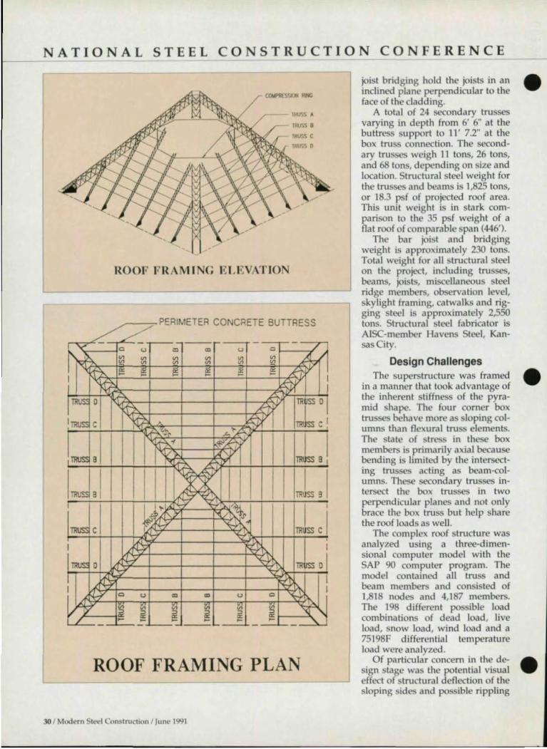
joist bridging hold the joists in an inclined plane perpendicular to the face of the cladding.
A total of 24 secondary trusses varying in depth from 6' 6" at the buttress support to 11' 7.2" at the box truss connection. The secondary trusses weigh 11 tons, 26 tons, and 68 tons, depending on size and location. Structural steel weight for the trusses and beams is 1,825 tons, or 18.3 psf of projected roof area. This unit weight is in stark comparison to the 35 psf weight of a flat roof of comparable span (446').
The bar joist and bridging weight is approximately 230 tons. Total weight for all structural steel on the project, including trusses, beams, joists, miscellaneous steel ridge members, observation level, skylight framing, catwalks and rigging steel is approximately 2,550 tons. Structural steel fabricator is AlSC-member Havens Steel, Kansas City.
Design Challenges The superstructure was framed
in a manner that took advantage of the inherent stiffness of the pyramid shape. The four corner box trusses behave more as sloping columns than flexural truss elements. The state of stress in these box members is primarily axial because bending is limited by the intersecting trusses acting as beam-columns. These secondary trusses intersect the box trusses in two perpendicular planes and not only brace the box truss but help share the roof loads as well.
The complex roof structure was analyzed using a three-dimensional computer model with the SAP 90 computer program. The model contained all truss and beam members and consisted of 1,818 nodes and 4,187 members. The 198 different possible load combinations of dead load, live load, snow load, wind load and a 75198F differential temperature load were analyzed.
Of particular concern in the design stage was the potential visual effect of structural deflection of the sloping sides and possible rippling
•
•
•

•
•
•
of the stainless steel cladding under load . The potential denection problem existed because of the different span lengths of the neighboring secondary trusses and the proximity of the maximum denection point of the B secondary truss to the nearby undenecting box truss (see diagram). A preliminary computer analysis revealed a 3.4" total deflection of the B truss under dead load .
Economic Design To adequately stiffen the roof
system without spending addi-
Because the pyramid shape is seldom
utilized, extensive wind tunnel tests were performed
tiona I dollars for steel weight, the structural engineer designed a compression ring beam connecting each secondary B truss at its bottom chord level. This ring beam system not only red uced the secondary B truss denection to 1.4" under dead load but also saved 120 tons of steel weight by reducing the effective length of the B trusses.
The architect and engineer also were concerned about fabrication tolerances, particularly camber perpendicular to the direction of the cladding, and the potential visual effects it would have on the cladding under different lighting conditions. As a result, special fabrication tolerances, rather than those defined by the AlSC Code of Standard Practice, were established for the trusses, beams, and bar joists.
Because the pyramid shape is seldom utilized in major modem structures, extensive wind tunnel tests were performed by RWDI. Inc., of Guelph, Ontario, Canada.
The study showed that approximately 90% of the cladding surface will experience wind pressures of 30 psf or less under a 50 year de-
sign storm. A maximum cladding pressure of 70 psf was identified at a few isolated comers near the base. These pressures proved to be significantly less than the pressures prescribed by the building code for a vertical wall building of comparable height.
RWDI also evaluated snow and ice p..lttcms, and as a result, the architect prescribed less insulation at the ridge cladding and provided heaters in the observation level stairs to prevent ice and snow build-up at these critical locations.
Metal !ita"s ",sjd~ tu:o of tile four box trusses prm,.dl! 8ro1wd In..,,'' access to OIl!
obsemafloll Inlt" . Ti,eSi' structural steel slfurs lucre falmcated and cotlstmeteil I',;or to erect iou ,
No aspect of construction planning on the project was given more attention then superstructure erection . Because some of the largest stresses induced in the superstructure occurred during erection, the structural engineer prescribed one possible sequence and method of erection on the bid documents and bidders were then allowed to bid the erection usmg the suggested sequence and lift points shown on the drawings without having to perform a design check. Alternately, they were allowed to bid using a
Modern 51N'I onstruct lon I June 1991 / 31

•

.... .- NATIONAL STE E L CONSTRUCTION CON FE R ENCE .-
• different erection procedure but only if they included a design check.
Superstructure Erection The successful erection subcon
tractor, Barnhart Construction Co., Memphis, elected to erect the superstructure using on central freestanding tower crane under the apex of the pyramid. This tower remained in place until the entire steel superstructure was connected. Two 250 ton cranes and two 150 ton cranes upplemented the center tower crane.
The first A box truss (see diagram) was lifted from lift points near the low end of the span with the two 150 tons cranes and near the upper end with the two 250 ton cranes. The center tower crane lifted the extreme upper end of the box truss. This lift was approximately 200 tons, with each pair of cranes ....... <me 150 ton and one 250 ton-rigged together to insure a 40%/60% load sharing.
~.
a demo, call : 1 (SOO) 332-7472 FAX: (714) 863-0244
17900 Sky Park Circle, SUlle 106 Irvine, CA 92714 RISA
II (: HN OIOGlf'
The upper cranes held the load while the lower cranes were used to erect the 0 and C secondary trusses on each side of the box truss.
The procedure was followed in a diagonally opposite quadrant and then in the two remaining quadrants. SubSe<Juent steps involved erection of the B trusses in each quadrant and finally the compression ring beams.
The linal stages involved erection of the middle bays on each of the four faces. The erector elected to panelize each 56'-wide by 60'long (up the slope) bar joist and brace beam bay into a single lift. These pa nelized bays were erected with the secondary trusses to provide the necessary truss bracing. The center tower crane was removed only after all of the structural steel was connected and prior to the erection of the skylight and stainless steel cladding panels.
The design used high strength slip-critical connections with over-
size and slotted holes .
Other Considerations Particular care was taken in
evaluating different cladding types. Alternatives considered included anodized aluminum, porcelain enamel, painted steel, and stainless steel. The cffects of pollutants, rain, icc, hail, temperature extremes, and window washing e<Juipment were considered. The owner opted for a 2"-thick stainless steel foam panel with metal deck underlayment. The approximately 8,000 panels, each 15' in length, were manufactured by E.C. Smith Construction Products.
IAwrellce G. GTlffis is sellior vIce presidellt alld director of strllctllral ellgilleerillg for Walter P. Moore alld Associate;;, tllC .. HOllstOIl . TillS artIcle was adapled fro", a paper he presellted at the Natimlnl Steel Constrllctioll COllferellce in Washlllgton, DC. 0
BEAM DETAILS In minutes
using "BEAMS. & COLUMNS" WI!' '.?-. ,.~. with AutoCAD ~l~
VERSION 4.0
ADDITIONAL FEATURES INCLUDE BILLS OF MA TERIAL SHOP CUTTING LISTS DRA WING MANAGEMENT
r-. OTHER PROGRAMS AVAILABLE FOR DETAILING
< __ '4.:.:!-
CAU NOW I
BEAMS. COlLMNS, "TAIRS. PLANS AND f'I.ElATIDNS. BRACINC. CU~·SFTS. MATERt AL MANACF!Jf:NT
for Injb1TNlhon about SG.Vlng hm. \tIdh productWdli programs from.
COMPUTER DETAILING CORPORATION 1310 Indult,111 Blvd. Southlmpton, PA 18988 215-355-8003
Modem St(>('J on~lruchon I Junl! 1991 / 33

AISC has given its seal of approval ~o only one business Insurance program.
The American Institute of Steel Construction has given its seal of approval to the business insurance program from the CNA Insurance Companies. The reason is our proven ability to respond to the specialized insurance needs you have because of the specialized nature of the work you do.
TIlis business insurance program provides a comprehensi\ package that can meet virtually all your business insurance needs. including commercial property, commercialliabilily, commercial auto. workers' compensation and commercial umbrella. TIle program also offers you the oppor-
tunity to be el igible for a safety group dividend' based on the eHici nt control of losses.
With the program's comprehensive approach to coverage - plus specialized loss control services and responsive claims handling - you can be assured of receiving the best value an associationendorsed program can offer You can be confident about the stability of your program, too. It's backed by the experience and financial strength of one of the nation's largest and most respected insurance organizations.
For more infomlation, call 1-800-CNA6241. 'Safety group drvIOends. available In mosI states, are dedared by CN~ Board of [Medora and cannot be guaranteecl
CNA for All thp ('ol1lrnitmen~ You Mak("
The CNA Insurance CompaJ1teS underwnbng CAM programs Wli vary according 10 the CO\Ier8ge. These compan.es Include TransportatIOn Insurance Companv_ valley Forge Insurance Company. Continental Casualty Company. NatlOMl Fire Insurance Company 01 Hartford, Amencan Casualty Company 01 Reachog, Pennsytvarna
or Transcontll'lentallnsurance Company CNA Plaza, Chicago. IL 60665
•
•
•

, ) '" " •
...L
•
•
•
NATI O NAL STE E L CONST R UCTI O N CON FE R E N CE
Vertical Expansion Of Vintage Buildings
An understanding of the design practices employed in the past can greatly simplify a renovation project
By Charles H. Thornton, P.E., Ph.D.; Udom Hungspruke; and Robert P. DeScenza, P.E.
(T/lis is the first part of a two-part artic/e. Tile secolld part will be presellted ill JlIly.)
L ike a fine red wine, the value of a vintage building improves with age-not only
because of inflation, but also because of the quality of the construction.
We've all heard the adage "they just don't build 'em like they used to." In spite of the deterioration and degradation of structures that occurs when they're not maintained, this adage is still true, especially when applied to existing structural steel buildings.
analysis and evaluation. This analysis must include an understanding of the construction methods prevalent when the structure was designed . By reviewing ASTM, AISC and other industry standards, the 20th Century can be divided into six vintage periods: 1900 to 1923; 1923 to 1936; 1936 to 1949; 1949 to 1960; 1960 to 1986; and 1986 to the present.
Five major areas should be explored when commencing an investigation into the potential for vertical expa nsion . • Review of as-built drawings (if
they exist) and field observations
ment . • ReVIew of the changes in func
tional use within the building.
As-Built Drawings Obtaining complete up-to-date
records pertaining to the construction of the building can save much of the time and expense otherwise required for the engineer to probe and measure the actual field onditions.
Ilowever, even if drawings are available, it is essential that the engineer confirm that they represent actual conditions, especially In
areas that are to be upgraded . Also, the engi
The quality of these old buildings often means that in many cases signifi-ca n t increased
gross and leasable l area can be added with little or no strengthening.
Even if drawings are available, it is essential that the engineer confirm that
they represent actual conditions, especially in areas that are to be
upgraded
ncer must carefully inspect the condition of representative structural elements for corrosion, cra kg or
1 deterioration.
Once drawing accuracy and struc-tural condition are known, the capacBecause of the
rapid rise in land costs during the past few decades, a keen interest on the part of owners and developers has materialized concerning the vertical expansion of existing buildings. In addition to the cost savings that can be realized by utilizing an existing structure, environmental and zoning approvals are essentially in place. Further, the project can often be completed more quickly than new construction.
But before any plans can be made, it is essential that a structural engineer perform an in-depth
and measurements of the existing structure.
• Comparisons of the analysis and design methods in usc at the original time of design to present pra tice.
• Comparison of the requirements of the prevailing codes and standards in effect at the time of the original design to the present requirements.
• Comparison of code provisions for live load and live load reductions at the time of the original design to the present require-
ity of members and connections can be evaluated. Samples of e.isting stcel should be taken as required, and tested to determine physical properties and weldability.
Analysis Methods Analytical and design methods
are continually changing, usually toward more precise methods that reduce the amount of steel required . In general, older structures were d6isned much more conservatively and have significant eXC6S structural capacity.
Modl'rn Sll't'l Con<;lrucbon I lunt' 1Q91 35

NATIONAL STEEL CONSTRUCTION CONFERENCE
r
Summary of Common Practice 1900-Present
1900-1923
CII_ ASTM A7 Q.CII
>.CII ASTM A9 I-Uj Cast Iron -0
1923·1936 1936-1960
ASTMA7 ASTMA7 ASTM A9
1960·Present
ASTMA7 ASTM A36
ASTM A572
No live load red. No live load red. live load reduction live load reduction
Working stress (prevalent)
Working stress Working stress Working stress
Design stress Design stress 16 ksi 18 ksi
Design stress 20 ksi
LRFD introduced
Design stress 20 - 24 ksi
Riveted conn.'s Riveted conn.'s Riveted conn.'s H.S. bolted conn.'s Bolted conn.'s Bolted conn.'s
Test steel for Weldable steel Weldable steel weldability generally found
1900-1923 Structural design of columns
began utilizing Euler's formula for slender columns. By 1910, the double modulus theory of column design became widely used.
Many construction methods and materials were designed and patented by manufacturers and contractors without formal calculations. During this period, the allowable stress in steel members was 16 ksi.
Several catastrophic fires at the end of the 19th Century resulted in major cities enacting building codes to govern construction. These codes were generally empirical and conservative in terms of allowable stresses and imposed loads.
However, due to their arbitrary nature, they may have been "unconservative" in certain areas. The loads given in these codes typically reflected the heavy construction materials, furniture and machinery typical of that period. Live load reductions were not allowed.
36 1 M odern Stt.'t'l Construction I June 1991
1923-1936 In 1923, the first specification of
the American Institute of Steel Construction formalized and standardized structural design for the first time. It was based on the use of ASTM A7 and A9 steels, and had an allowable basic working stress of 18 ksi. This standard had a total of five formulae and a set of fixed allowable stresses. During this period, analysis of indeterminate structures wa& performed using Hardy Cross's technique of moment distribution.
Building codes were very slow to change during this period. Live load reductions began to be incorporated, but they typically were very small and limited to columns. The effect of impact loads was generallyacknowledged.
1936-1 949 As improved mill practices re
sulted in more uniform steel, AlSC increased the allowable basic working stress to 20 ksi. Research continued regarding inelastic column design and resulted in Shanley'S
Weldable steel
Theory in 1947 and Johnson's Parabola.
Building codes became more specific and addressed a greater variety of construction materials. Wind loads were understood to vary over the height of structures. Live load reductions were increased.
1949-1960 In 1949, the Mallual of Sleel COll
s/rllelion adopted the tangent modulus theory for the design of short columns. This edition also shifted from an allowable basic working stress with reductions, to calculations based on steel yield strength with safety factors. Research laboratories such as the one at Lehigh University produced technical data for analysis and development. It was at Lehigh that residual steel stresses were discovered during the 195Os.
The codes continued to become more specific. The allowable stress increases associated with wind loads were better defined. Snow loads were revised to better address
•
•
•

.-w
• drift conditions. Building codes continued to increase the variety of construction materials addressed. Most codes continued to provide formulae and design guidelines for the design of structural members, although standards such as those in the Manual of Steel Construction were gaining increased acceptance.
1960-1986 Analysis of complex structures
was made vastly easier in the 1960s with the entrance of computer capabilities into design offices. Deigners took advantage of these
new tools and new design methods such as composite beam design to make designs more efficient. The MD>lIIal of Steel COllstructioll was continuously updated to incorporate new steel types and in 1969, it revised the column design fonnulae to address residual steel stresses.
FOR FASTENING METAL OR FIBERGLASS BAR GRATING
• ONE MAN FROM ABOVE • NO WELDING • NO DRILLING • NO PENETRATION OF STEEL OR COATING • AS EASY TO REMOVE AS IT IS TO INSTALL
• VERSATILITY FOR CONSTRUCTABILITY.
Struct-Fast Inc., 20 Walnut Street, Suite 101 , Wellesley Hills, MA 02181 Tel. 617 235 6734 Fax: 617 431 7940 Wats: 800 327 6719
Live load requirements were ad- I .~~;:;:;~~~~~~~~~~~;;;;;;;;;;: justed to reflect more modern us- r ages and occupancies. Wind load requirements were revised to incorporate intensive laboratory research by the American ational Standards lnstitute.
•
•
1986-Present Design methods continue to im
prove. The new AlSC Load alld Resistance Factor Desigll Manual makes it possible to design steel based on I its ultimate strength and permits greater efficiency in design. Computer techniques continue to improve with optimization programs to make designs more efficient. Desktop computers make complex analysis techniques available to even the smallest office. Seismic and wind requirements also continue to be reviewed and enhanced .
Charles H. TllOmtoll is chairman and principal of tile NF:W York Citybased consulting firm of Thorntoll Tomasetti Engineers. Udom Hungspnlke is a vice president and Robert P. DeSce".zA is an associate with Thorntoll Tomasetti Engineers. This article was adapted from a paper presellted at the Natiollal Steel COIl
struction Conference. 0
O..........:NCO""" I ... ""'-__ 0 oc IHCL.OB) I
""~
Modern Stl'el onstrudlon I Junl' 1991 / 31

NATIONAL S TE EL CONSTRUCTION CONFERENCE
Vertical Expansion To Add 235,000 Sq. Ft.
By Charles H. Thornton, P.E., Ph.D.; Udom Hungspruke; and Robert P. DeScenza, P.E.
TIle proposed additioll to tI" building would add mre story to the courtyard area, four stories to the Cfnter portioll, tmd Sl1.lfn
stories to ti,e IIew .. 'miler" seCtiO', .
'~'-r i ,II" h_, ~ '::=~ ,.""~-I I J ... ·~ ...
~ "'" H_~--· g ""'n_~ ~ ,0'" f,-r--. ~ :::=t=: '!' ........ _l_. .=: ..... ~~-
\ ... ,..-~-, :~~ _'l._~_'
o S' , .... ~ __
... (.O,tt, n • ., ~-.,." .... 00.. • .,
~ ,
~ • ;
CClLL..MrI LOAD
38 / Modt'rn St~1 Construction I June 1991
'" M.
OM'
... •• ~.
! ! g ! ;
! , . I
.' N'
_. "'~ ... ",. S'.. 4lt_
". -"' ,.,.' _c ft .. ' ~'I N'. !>I" .... ~ • • . ,; ,,=
~ ,.-,5t is ! , \ ! ; ;
COMPARISON
When it was built in various stages between 1906 and 1913, the B. Altman
Department Store was the architectural centerpiece of ew York's commercial district. Today, it's a registered historic landmark occupying an entire city block from Fifth Avenue to Madison Avenue and from 34th Street to 35th Street.
Most of the building is nine-stories high, except for the 120' -wide portion on the east side, which is
What makes the project possible is
the trade-off of loads, which required the
lightest possible flOOJ system to work
13-stories high and is known as the Bustle Area.
The proposed vertical expansion approved by the Landmark Commission will make a drastic change in the appearance of the building. The expansion consists of adding height to the building in three zones: • Courtyard Area. One additional
story on the west side of the building .
• Pavilion Area. Four-stories in the center portion of the building.
• Tower Area. Seven-stories over the entire 120' -wide Bustle area of the structure. The three additions will raise
the building to a total of 20 stories and will add 235,000 sq. ft. to the
•
•
•

•
•
•
existing 900,000 sq. ft. When the project was conceived,
there was a desire to add as many floors as possible to the Bustle area. A major constraint was that any required reinforcement of the columns could only be provided above the sixth floor slab. Any construction below the sixth floor slab was not allowed because of its impact on the existing retail activity, which would remain in operation up through the fifth floor of the bujlding.
After careful evaluation of the reserve capacity in the existing columns, it was found to be feasible to add seven floors. In addition to using the lightest possible floor framing ystem, the addition was made possible by various changes in design and construction methods.
Design Methods The B. Altman building was
built in the early 1900s when the prevailing allowable stress in structural steel members was 16 ksi. At present, the allowable stress is .66 fy. For ASTM A7 steel with today's code, the allowable stress is equal to .66 x 33 ksi = 22 ksi. Using this item, the increase in total capacity of the existing columns is approximately 35%.
Loading Requirements The occupancy loading require
ments have gone through many changes during the past 85 years In the case of the B. Altman building, the entire building was designed for retail use, which, at that time, required a 125 psf live load . The current ew York City code requires a 75 psf live load for retail areas at grade. Using this item, 50 psf in reserve capacity is realized . With a typical column spacing of 21' x 21', thi reserve capacity amounts to approximately 22 kips per floor.
Occupancy Changes After it is renovated (the project
is currently on hold as a result of
---"---.. to._ .......
. "
.'-
T"I~C""" eJU,ll'1N lite' "'~ce~""T ~'''''-.LN ~~L
j Ma"y of tht tXIstmg steel columns wert strt!".~tlli!tlfd will, rf",/orcm8 platl!S 0" tlrr
flanges of tlu! columns.
New York's glutted office market), the B. Altman building will have a mixed-use occupancy consisting of retail through the fifth floor and office space above.
The current ew York City code requires 50 psf live load for office areaS. Therefore, 75 psf in reserve capacity is realized in those areas where the office occupancy replaces retail area.
Live Load Reduction In the office area where the live
load is SO psf, the current New York City code allows a reduction in live load based upon the tributary area supported by the element being designed. For columns and foundations, the live load reduction could be up to 60%.
Roof Requirements The existing roof above the 13th
floor was originally constructed with slopes to drain. A thick cinder fill with an approximate average weight of 140 psf was used to create the slope. Since the slope rendered the roof unusable as a floor for the addition, it was replaced with a lighter concrete slab on
metal deck with an approximate weight of 45 psf. Thb replacement of floor structure contributes to additional reserve capacity.
Two schemes were devised (or those columns that nceded additional reinforcement: either providing reinforcing plates on the flanges of the existing columns or encaSing the existing column with concrete. Adding reinforcing plates is simpler and results in a smaller overall section, though the built-up column requires fireproofing and finish column encasement.
In both schemes, proper transfer of the load in the rein for ed columns must be achieved at each of the floor slabs.
What makes the project possible is the trade-off of loads, whl h required the lightest possible floor system to work.
The system chosen was a steel frame with a composite slab of 2" metal decking and 21/2" of lightweight concrete. The new W 12 columns are located directly above ea h of the existing columns so Io.lds are evenly distributed . The stnlctural framing is designed using W12 beams and WI6 girders, 0
M .. k.ll'rn Stet.'1 Construction I June 1991 / 39

NATIONAL STEEL C O NST R UC TION CON FE RENC E
Preserving Cleveland's History
The interior of this landmark was completely rebuilt above the second floor to create modern office space
/
1 J j , I t I I I I I I
dld l I
Tire ",trrlOr of this 1888 bllilding UNlS completely rebuilt to create mode", office space. PI.otography by Mort Tucker Photography.
40 I Modern Sleel onstructlon I Ju ne 1991
By Gary E. Thayer, P.E., and Kurt K.Rim,P.E.
Cleveland's resurgence during the last decade unfortunately resulted in the demolition of
some the city's historical past. But with the growth of the preservation movement, important structures are increasingly being saved.
The Society National Bank Building, located on the north side of Public Square in downtown Cleveland, is a 12-story red sandstone office tower designed by Burnham and Root in 1888. In its day, the National Register building was the tallest "Skyscraper" between New York and Chicago.
The building's main feature is its ornate Arts and Crafts two-story banking hall with coffered, luminous, stained-glass ceiling.
At the south end of this banking hall is a mezzanine level that is entirely devoted to use as a board room for Society Bank. The board room is a rich space, finished on all surfaces with hand carved oak, and would be impossible to economically duplicate today.
The interior of the building is constructed of a steel post and beam skeleton with 15" of flat clay tile arch construction originally overlaid with a floor system composed of cinders and wood sleepers, then finished with oak flooring .
At the core of the steel-framed building was an atrium light well capped at the roof level with a delicate steel-and-glass skylight that, over the years, was covered with insulation and roofing and rendered unusable.
In 1987, The Osborn Engineering
•
•
•
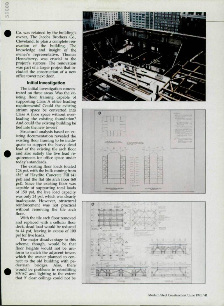
,!) cD
'''' ,,., '.'1
•
•
•
Co. was retained by the building's owner, The Jacobs Brothers Co., Cleveland, to plan a complete renovation of the building. The knowledge and insight of the owner's representative, Thomas Henneberry, was crucial to the project's success. The renovation was part of a larger project that included the construction of a new office tower next door.
Initial Investigation The initial investigation concen
trated on three areas. Was the existing noor framing capable of supporting Class A office loading requirements? Could the existing atrium space be converted into Class A noor space without overloading the existing foundation? And could the existing building be tied into the new tower?
Structural analysis based on existing documentation revealed the existing noor framing to be inadequate to support the heavy dead load of the existing tile arch noor and also satisfy the live load requirements for office space under todays standards.
The existing noor loads totaled 126 pst with the bulk coming from 4Vz" of Haydite Concrete Fill (41 psf) and the nat tile arch noor (68 psf). Since the existing noor was capable of supporting total loads of 150 psf, the live load capacity was only 24 psf, which was clearly inadequate. However, structural reinforcement was not practical without removing the tile arch noor.
With the tile arch noor removed and replaced with a cellular noor deck, dead load would be reduced to 44 psf, leaving in excess of 1 ()() psf for live loads.
The major disadvantage to this scheme, though, would be that noor heights would not be uniform to match the adjacent tower, which the owner planned to connect to the old building with pedestrian bridges. Also, there would be problems in retrofitting HV AC and lighting to the extent that 9' clear ceilings could not be
o
0 0,
. '
I I
-"",-.-:-'
• n s
" .; ; .
,
•
"
•
Modern Steel Construct ion I June 1991 / 41

NATIONAL STEEL CONSTRUCTION CONFERENCE
The superstructure supports tlte six Ilew core cO/lmms and transfers their reactious to tile lower grid.
New from Janey Engineering
JM-101 Slugger® Portable Magnetic Holemaking System
Lightweight-Accurate-Ourable Convenient-Affordable
~'; Slugger
by Janey Engineering Co. Kimmel Or - P.O. Box 3098
Davenport. Iowa 52808 319-326-6251 • FAX 319-326-0949
Ask for Will or Dave
42 1 Modern Steel Construction I June 1991
maintained. • After analyzing the existing con
ditions, the engineer proposed a bold plan to structurally renovate the entire building from the second level on up. The existing facade would be restored, the banking haU saved, and the interior floors above the second level realigned to match the tower. Also, the existing atrium would be filled in at each level to increase rentable space. The plan also called for reducing the number of interior core columns from 14 to six and aligning them with the space planning module of the tower.
In order to succeed, the design reqUired a huge transfer structure located above the banking hall and occupying the entire second floor. Initial estimates were for a structure weighing some 250 tons.
Structural Analysis The first step was a complete
The Best Selling CivillStructural Program Since 1987
II ANALYSIS II
• 20/10 Frame I Truss I Plate I Shell • Static I P·Delta l Dynamic I RSA Analysis • ClIp;able of 1000's of joints .. nd laO's of
IOild cases • Moving load generator • Interactive geometry, deflection, mode
shape, plots • Inlenctive shear and moment diagram plots • AISC library Included
UDESIGN II
• Inter~ctiye gr~phk menu driven deslg" • Continuous beam. section properties.
frequency calculations • AISC code check and sillng Including lRFO • ACt column. beam. footing . ret~ining wall design • Design details can be outpYt to AUTOCAO • Excellent In report presentations
II SATISFACTION GUARANTEED-II ' See our brochure for details Supports 005/052 operation systems
"Ask for a brochure todaylll You'll be glad you did.
P.O. Box 7]26 Fremont, CA 945]6·7]26
(415) 795·0509 Fax (415) 795·0918

·-
• structural field survey to define the capabilities and limitations of the lOO-year-old structure. Included were tests to verify the composition and weldability of the steel skeleton, as well as verify locations of critical column and beams and identify the types of connections and foundations.
One of the first areas explored were the footings. Excavations were made in the basement floor adjacent to the stepped sandstone footings by the contractor, Turner Construction Co. It was discovered that the large sandstone foundation was laid up from a grillage of rails poured solid with concrete and it had an allowable bearing capacity in excess of 5,000 psf.
At the same time that the foundations were being investigated, basic column sizes and locations were being verified at the upper levels. Center-to-center dimensions were thoroughly checked against
SDS/2 assures fittIng solutions again and again.
Call Design Data-1-800-443-0782. It's
references and walls and pilasters were opened on every floor to check orientation and cross section.
The thoroughness of this investigation proved crucial. ot only were the existing columns oriented differently from the references, they were not of the same cross section or material as referenced . As we would tearn throughout this project, when renovating a structure, make no assumptions. Verify everything. In this case, columns that were referenced as circular and made from cast iron were actually built-up of steel "Z" sections and plate.
Materials Testing When coupons were taken from
the existing structure, another surprising discovery was made. The steel used on this bui lding 100 year ago was the near equivalent to today's A36 in both chemistry and strength.
TIt£' I'lIt,re stmcturt' aOOt1f.' ,ht' st',:oml floorlOOs rt'llotlRlt'd.
1-80H43-8782 U2-47H278
Mooern Stet.'! Con~lructlon JUI'M,-" 1~1 / 43

NATIONAL ST E EL CONSTRUCTION CONFERENCE
However, a potential problem was noted in terms of weldability. An elevated "spike" in the phosphorous content of the low carbon alloy meant the potential for cold cracking of welds used to make connections. Fortunately, visual and bend tests made by a testing laboratory in accordance with the Structural Welding Code proved that the material could be welded
44 1 Modern Steel Construction J June 1991
without a problem.
Transfer Structure By replacing the old, heavy floor
system with a modern, light-weight system, it was possible to rebuild the entire interior of the structure above the second floor-including infilling eight floors of atrium space-without reinforcing the existing columns. The rebuilt floors increased the leasable area of the
METAL DECKS STEEL JOISTS
TRUSS GIRDERS
For over 35 years, Riopelle has been providing customers with high quality. S.J.I. Specification steel bar 101StS, ASCE Standard metal decks.
Fast Estimates: Fax us your lists or send us your plans
Quick In· House Detailing
Delivery When You Want It
. Structural Engineering
We serve all fabricators and struc-tural engineers. Our large volume assures both fast delivery and highly-competitive quotes. No Job IS
too big or too small. International shipments available.
For unbeatable prices and favorable credit terms, give us a call today.
Call Collect : 414-353-8080 FAX: 414-353-8093
RIOPELLE ENGINEERING SALES INC 8817 West Lynx Avenue Milwaukee, Wisconsin 53225-1833 U.S.A.
building by 30%. The 14 existing columns were
left in place up through the second floor. Attached to the existing columns at the second level is a trans-fer structure, which in turn supports six new columns.
The transfer structure had three distinct components: superstructure; lower grid; and hanger support steel.
The superstructure supports the six new core columns and transfers their reactions to the lower grid. It includes "knuckles", which connect the columns and the primary load transfer members. These members include one "vertical" and two "diagonals" at each knuckle.
The lower grid is a sturdy and highly redundant steel grid suspended by rods approximately l ' above the existing second floor. It acts as the lower portion of the three-dimensional, space frame-type transfer structure and takes the resultant tension forces. Also, the lower grid acted as a work platform during construction keeping the heavy loads of the superstruc-ture off of the second floor.
The hanger support steel includes 28 6"-diameter steel "hanger rods" that suspend the lower grid and the hanger support beams and plates that transfer vertical reactions from the lower grid into the 14 existing interior columns at the second level.
Structural Design The new structural system was
analyzed using the Ranul Stress computer software package from Ranul, Inc., Baltimore.
The basic analytical problem was how to direct the reaction of the six new columns in the proper proportion through the transfer structure.
The solution was for the diagOoo nals in the transfer structure to be selected and detailed to encourage
•
•
the load from the new column to • distribute down the diagonal prOoo portionally to adjacent columns rather than vertically to the nearest
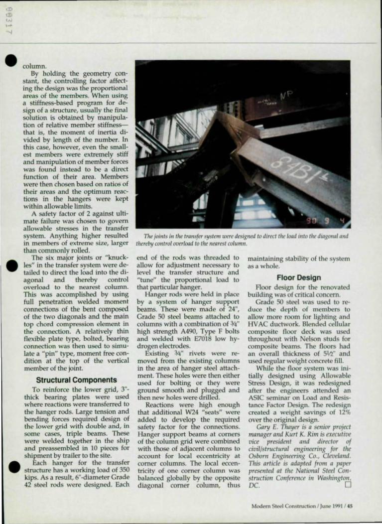
•
•
•
column. By holding the geometry con
stant, the controlling factor affecting the design was the proportional areas of the members. When using a stiffness-based program for design of a structure, usually the final solution is obtained by manipulation of relative member stiffnessthat is, the moment of inertia divided by length of the number. In this case, however, even the smallest members were extremely stiff and manipulation of member forces was found instead to be a direct function of their area. Members were then chosen based on ratios of their areas and the optimum reactions in the hangers were kept within allowable limits.
A safety factor of 2 against ultimate failure was chosen to govern allowable stresses in the transfer system. Anything higher resulted in members of extreme size, larger than commonly rolled.
The six major joints or "knuckles" in the transfer system were detailed to direct the load into the diagonal and thereby control overload to the nearest column. This was accomplished by using full penetration welded moment connections of the bent composed of the two diagonals and the main top chord compression element in the connection. A relatively thin flexible plate type, bolted, bearing connection was then used to simu· late a "pin" type, moment free condition at the top of the vertical member of the joint.
Structural Components To reinforce the lower grid, 3"
thick bearing plates were used where reactions were transferred to the hanger rods. Large tension and bending forces required design of the lower grid with double and, in some cases, triple beams. These were welded together in the ship and preassembled in 10 pieces for shipment by trailer to the site.
Each hanger for the transfer structure has a working load of 350 kips. As a result, 6"-diameter Grade 42 steel rods were designed. Each
TI.e joints in tire transfer system were designed to direct the load mlo the diagmral "lid thereby control overload to ti,e "rarest column.
end of the rods was threaded to allow for adjustment necessary to level the transfer structure and "tune" the proportional load to that particular hanger.
Hanger rods were held in place by a system of hanger support beams. These were made of 24", Grade 50 steel beams attached to columns with a combination of :)14"
high strength A490, Type F bolts and welded with E7018 low hydrogen electrodes.
Existing 414" rivets were removed from the existing columns in the area of hanger steel attachment. These holes were then either used for bolting or they were ground smooth and plugged and then new holes were drilled.
Reactions were high enough that additional W24 "seats" were added to develop the required safety factor for the connections. Hanger support beams at corners of the column grid were combined with those of adjacent columns to account for local eccentricity at comer columns. The local eccentricity of one comer column was balanced globally by the opposite diagonal corner column, thus
maintaining stability of the sy tern asa whole.
Floor Design Floor design for the renovated
building was of critical concern. Grade 50 steel was used to re
duce the depth of members to allow more room for lighting and HV AC ductwork. Blended cellular composite floor deck was used throughout with elson stud for composite beams. The floors had an overall thIckness of Sin" and used regular weight concrete fill.
Whi le the floor system was initially designed using Allowable Stress Design, it was red esigned after the engineers attended an ASIC seminar on Load and Resistance Factor Design. The redesign created a weight savings of 12% over the original design.
Cary E. Thayer is a senior project manager and Kllrt K. Rim is execut,ve vice president and director of civil/structllral engilleerillg for tlte Osborn Ellgilleenllg Co., Clet.>elalld . TI,is article is adapted from a paper presellted at tlte NatlOllal Steel eollstructioll COllferellce ilf Was/llllgtolf. De. 0
Modern Steel Construction / Jun(' 1991 / 45

NATIONAL STEEL CONSTRUCTION CONFERENCE
A beautiful steel bridge was
econom ically strengthened and
modified to handle heavier
loads on a wider and safer roadway
By Arthur W. Hodgron, Ph.D., P.E. and William Schmitt, P.E.
46 / Modern Steel Construction I June 1991
Bridge Expansion • Spanning the MiSS.issiPPi River
between Dubuque, lA, and East Dubuque, IL, is the 48-
year-old Julien Dubuque Bridge. Due to deteriorated conditions, the bridge requires rehabilitation. But at the same time, since traffic on the bridge is expected to increase from a 19,000 vehicles on an average day to 21,900 in the year 2008, the Iowa OOT decided to also expandit.
The project included field inspection, widening the deck, member strengthening, and structural repairs. The Pittsburgh office of HDR Engineering, Inc., was the engineer.
The total length of the bridge between centerJines of abutment bearings is approximately 5,760', including 1,448' of girder approach spans on the Iowa side, a threespan through arched truss unit 1,539' long over the river, and 2,773' of girder spans on the illinois approach.
The existing bridge deck pro-
vides a 24' roadway curb-to-curb, a 5' concrete pedestrian sidewalk on the north side, and a steel safety walk on the south side. The remodeled curb-to-curb width will be 28' with 4' widening on the north side. A 4' 6" sidewall will be located on the south side of the remodeled structure.
Bridge Renovation The westernmost 512' of the
Iowa approach spans is being entirely reconstructed. This reconstruction extends from the existing west abutment to the hinge point in the existing Span 10. The renovation will remove the roadway deck, sidewalk, safety walk, and railings and the remaining 5,248' length of the bridge-from the hinge point in existing Span 10 to the existing east abutment- will be remodeled .
The deck replacement and rat- • ing analysis of the steel structure for the alternatives included: castin-place (both normal weight and

,,0
•
Handles Additional Traffic •
•
lightweight concrete); precast (both normal weight and lightweight concrete); orthotropic (steel orthotropic); exodermic (steel grid and reinforced concrete composite of either normal weight or lightweight concrete); and a partiallyfilled steel grid (both norma I weight and lightweight concrete).
Design Criteria The Service Load Design
Method was used in the analysis of main truss members. The Strength Design Method (Load Factor) was used for girder spans and the floor system of the truss spans.
Carbon steel ASTM A7 or silkon steel ASTM A94 were used for the eXIsting structural components with yield strengths of 33,000 psi and 45,000 psi, respectively. Ten silicon steel test samples were taken at various truss member locations to determine if a yield strength of 50,000 psi could be used for the silicon steel. However, test results indicated yields be-
tween 45,000 and 50,000 psi. Therefore, the analysis for strengthening the silicon steel members is based on 45,000 psi.
Design live loading was increased from H20, used in the original design, to H520.
Truss And Approach Spans Due to the Iowa DOT's prefer
ence, regular weight concrete was used despite requiring a larger number of members to be strengthened and conSiderably thicker strengthening plates.
Girders in the approach spans were strengthened by adding and/or increasing the lengths of top flange cover plates and by providing shear connectors to obtain a composite designed section. Also, struts were added to brace bottom flanges adjacent to piers.
Upgrading the live load from H20 to 11520 required strengthening of all floor beams in the truss spans and in the girder spans. Floor beams in the truss spans
were strengthened by adding shear connectors, while floor beams in the approach spans were strengthened by adding only a bottom flange cover plate smce the stnngers are continuous over the noor beams.
Because the deck beams on truss spans prevented adding plates to the top of stringer top flanges, the existing south stringer was strengthened by adding web side plates near the top of the stringer and a bottom flange plate. The addition of a new stringer on the north side eliminated the need to strengthen the existing north stnnger.
Additional Stringer Widemng of the roadway m the
truss spans necessitated adding an additional stringer on the north side and extendmg the deck beams. Also, sidewalk brackets arc attached to the outside of the south truss.
Widening of the approach spans
Mod{'rn Stt.'t'l Conc.,tructlon I Junt.' 1'>91 / 47

NATIONAL STEEL CONSTRUCTION CONFERENCE
......
A'&A
CRf" r.~ W(fI t Ii ," lGtll PR01RVOtfC .t80v( '8 rlC.lS
Shown at right is tht sidf!U",/A remol"tll on the txistm8 portIO" of Ih, lui .. " Dubuque Bridge over lite Mississippi Rit'fr.
lS 1040%
SOUTH lR1JSS
48 / Modem S',-ocl Construction I Jun(' 1991
J'-a~ c.e. SIRes.
(XISTING OthGONAt.
, ~
required replacement of the sidewalk stringer with a roadway stringer and replacement of all brackets. Moving the sidewalk to the south side required replacement of all the existing curb brackets with sidewalk brackets and the addition of a new sidewalk stringer.
Roadway Widening The roadway widening and re
location of the sidewalk necessitated modification of the East Abutment and the approach roadway. The approach roadway plans were developed under subcontract to Lee & Batheja, Omaha, while HDR designs included the development of sidewalk details and wall brackets to carry the sidewalk around the existing south pylon. The design of the bridge deck, railing and fence over the bridge was subcontracted to Greiner, Inc., Timonium, MD.
The rehabilitation of the bridge included replacement of all deck expansion joints with sealed types of joints. Deteriorated steel components at the joints were repaired or replaced as required .
950 Tons Of Steel The bridge strengthening, wid
ening and rehabilitation of deteriorated steel sections required approximately 950 tons of new steel.
Nearly all existing built-up members and connections are riveted, while high strength bolts are used for all new connections.
A low bid of $13,407,514 was submitted by Johnson Bros. Corp. of Litchfield, MN. The bridge was closed to traffic on Feb. 4, 1991 , and is to be reopened on Dec. 1, 1991.
Arlllllr W. Hedgrell , Jr. , is a vice presidenl and William Schmill is a {{J/lslIl/alll will,'he Pillsbllrgh office of HDR Ellgilleering, IIIC., a wel/-kllowlI ellgilleerillg firm headqllarlered III Omaha. This arliele is ada pled from a
•
•
paper Ihey presellied al lI,is years Na- • liollal Sleel COIIs/ruelioll COllferellce ill Washillgloll, DC. 0

•
•
•
FIR E PROT E CTIO N PROD UCT S
Carboline
Pyrocrete Fireproofing is the most durable, impact-resistant,
weather-resistant cementitious fireproofing material on the market today. They form a hard, permanent protective layer that is 60% lighter than concrete or Gunnite allowing for reduced structural loading. Individual product sheets are available on: Pyrocrete 241 (exterior installations); Pyrocrete 240 (limited fire ratings); Pyrocrete LID (protection of foamed plastics); Pyrocrete 239 (architectural steel); Pyrocrete 301 (plaster-like finish) ; Pyrofoam 700 (heat resistant thermal barrier); and Intumastic 285 (cable and cable tray protection).
For more information, contact: Carboline Fireproofing Products Division, 35O Hanley Industrial Ct., St. Louis, MO 63144-1599 (314) 644-1000.
Textron Specialty Materials
Chartek Fireproofing provides long-life fire and corrosion
protection with a patented mesh system. On new construction or when replacing an eXisting system, the Chartek coating delivers a tough, durable, and weatherable finish that is inert to most chemicals. And if there is a fire, the mesh stays rigid while the fireproofing expands its thickness to six times its application thickness. The epoxy coating forms a cocoon-like char that provides insulation from the fire while it directs the fire' s energy away from the substrate. The same mesh that reinforces the char during a fire makes the system more durable when there is no fire. It prevents peel-back at free edges and provides greater resistance to impact damage. The system is durable enough to be applied prior to the steel members being shipped to a site, which means the system can be installed without disturbing other building trades. The system can be used for pre-erection con-
struction, columns, beams, tUbu-l lars, walls, underdecks, and cable tray enclosures. I
For more information, contact: Chartek Fireproofing, Textron Specialty Materials, Two Industrial Ave., Lowell, MA 01851 (SOB) 452-8961.
StanChem Inc.
A lbi Manufacturing offers fireretardent coatings as well as
spray-on fireproofing and intumescent fireproofing mastics. The coatings can be applied both to combustible surfaces and to supplement fire protection on steel members. The coatings are available in water- or solvent-based systems in a variety of colors. Both spray-on fireproofing systems are fiber-reinforced magnesium oxychloride cement-based systems. One sy tem is designed only for interior uses while the other is designed for a variety of applications, including parking structures. When spray-applied, it hardens to a Stucco-like finish. It can also be hand trowelled.
For more information, contact: Albi, 401 Berlin St., East Berlin, CT 06023 (203) 828-0571 .
SCHOOLS CANOPIES AIRPORTS CONVENTION CENTERS STADIUMS INSTITUTIONS AUDITORIUMS CHURCHES SWIMMING POOLS PRISONS THEATRES
• Provide structural and ceiling mot&rial all In one orchltectural element
• Provides long spans Without mid-span tastenlng
Grace Construction • Wide choice at depths and design thicknesses
Products • Ideollysuned to any type
W.R. race & Co. has intro- I construction duced a high density, ' . Presents a uniform ceiling with no
spray-applied cementitious fire- Irregular gaps proofing, Zonolite Type Z146. The • Design with our acoustical treatment
to ochleve stote'of-the-art solutions product is designed for industrial to sound control and manufacturing facilities and • Blend conlrol-use acoustic and exterior use. It combines excellent non-acoustic panels together s tructural s teel fire ratings, ease of ECONO Y THROUGH SELECTION use, and excellent in-place physi- • Roof Docl< • PIo1tc1 Deck . Compos". Deck
cal properties to perform in high- INI UM MAINTENANCE abuse areas. The material can be AST ERECTION applied with a wide variety of T E CHOICE IS YOURSI common plaster pumping equip-ment, which eliminates the need 'O R IN f ORMA TI ON , C ON TACT
for specialty pumps. For more information, contact:
Marketing ommunication Dept., Grace Construction Prod ucts Divi
PIC sion, 62 Whittemore Ave., Cam- Eleven Talbot Avenue. Ronk,n All 15104 bridge, MA 02140 (617) 876-1400. PHONE 412/3513913
FAX 412/351 ·2018
Modern SIl"t.'1 Construchon I Jun(' 19C) 1 / 49

Advertisers' Index A
AAAA (Amer. Assoc. of Adv. Agencies) ...... . 20 AISC Bridge Symposium ........ .... ....... ........ .... CIII A1SC Computer Software .. ........... .. ..... . 19 Arkansas Steel Processing, Inc .. ........ .. .. ... ........ 25
B Bethlehem Steel .............................................. 14-15 Bouras, Nicholas J ....... ... .......... ........................ . CII
C CAST (Computer Aided Structural Tech.) .... .42 C A Insurance ......... ....... ...... ........ ...... ............... 34 Chaparral Steel ..... ............... ........ .......................... 8 Computers & Structures, Inc. .............. .. ........ CIV Computer Detailing Corp .......... ....................... 33
o Design Data Corp . ................. ........... ....... .......... .43 Dogwood Technologies ....... ..... ............ 13
E EJE Industries ...................................................... 10 EPIC Metals ..... ........... ... ........... ........................... 49
J Jancy Engineering ............................................. .. 42
N NSS Industries .......................................... .......... . 11 N ucor Fastener .... ...... ......... ................................... 7
o Omnitech .............................................................. 10
50 I Modern Steel Constnlction I June 1991
R RlSA ...................................................................... 33 Research Engineers Inc. ......................... ............ 16 Riopelle ............ .... .... ... .. ... ....... .. .... .... ................... 44
S SAl (Structural Analysis, Inc.) .......................... 37 St. Louis Screw & Bolt ....................................... 18 Steelcad International .................................... .... 22 Struct-Fast Inc .................................... .... .... ......... 37 Structural Software ............... .......... .... ....... ..... ..... 3
T TradeARBED, Inc. ................ ... .... ... ..... ..... ............ 5
V Vulcraft ......... .... ... ..... ...... ... ...... ....................... 26-27
For advertising information, contact:
Eric K. Nieman Pattis/3M 7161 North Cicero Lincolnwood, IL 60646 (708) 679-11 ()() FAX (708) 679-5926
For advertising information in OK, NE, KS, SO, NO, MN, CA, MT, WY, CO, NM, AZ, UT, 10, WA, OR, HI, AK, and Canada, contact:
Ed Sreniawski Pattis/3M 7161 North Cicero Lincolnwood, IL 60646 (708) 679-11 ()() FAX (708) 679-5926
•
•
•

I •
•
The Third National Symposium on Steel Bridge Construction is a program that offers eminently qualified speakers presenting current practices dealing with steel bridge construction. More importantly, it will deal with the co-relation of design techniques, fabrication, detailing and erection principles. The theme is: "To create a dialogue between owners, designers and builders to enhance the economy, quality and reliability of steel bridges."
The symposium has been designed to meet the need for a first-class, hands-on national program addressing the specifics of steel bridge construction. It will benefit fabricators, erectors, designers, owners and bridge contractors.
Highlights:
Painting workshop In-depth reports on recently completed outstanding steel bridges Deisgn & contructability panel Short span bridges
• FHWA research programs Economical details
• Fatigue workshop
For more information:
Complete this form and send it to : The American Institute of Steel Construction , Inc., One East Wacker Dr., Suite 3100, Chicago IL 60601 -2001 , Attn : Lewis Brunner.
Name:
Affiliation : ________ _
Address:
Or call Lewis Brunner at (312) 670-5420.
- LI _'_" '_"_" '_" '_" '_" '_" '_" '_" '_" ._ .. _ ... ..... ......... .
THE NATIONAL SYMPOSIUM ON
STEEL BRIDGE CONSTRUCTION
September 16-17, 1991
The Adam's Mark Hotel St. Louis, MO
• Co-sponsored by
The F.d,,,1 H,ghw'r AdmHIIS'''tltHI Amenc." k$OCh!hOIl 01 St." Hlghw-V end r,.nsporr.tJOfI OH'H;~I$
Th. Am.ne,,, Iron 1ft(} S"tllnstJtur, Th. Am,ne,,, I"SIIM' 01 S,MI COMtnI('fIOtI
IQIOI@
