one-man-band: a touch screen interface for producing live multi
TRANSCRIPT
One-Man-Band: A Touch Screen Interface for ProducingLive Multi-Camera Sports Broadcasts
Eric FooteDisney ResearchPittsburgh, USA
Peter CarrDisney ResearchPittsburgh, USA
Patrick LuceyDisney ResearchPittsburgh, USA
[email protected] Sheikh
Carnegie Mellon UniversityPittsburgh, USA
Iain MatthewsDisney ResearchPittsburgh, USA
Generating live broadcasts of sporting events requires acoordinated crew of camera operators, directors, and tech-nical personnel to control and switch between multiple cam-eras to tell the evolving story of a game. In this paper,we present an unimodal interface concept that allows oneperson to cover live sporting action by controlling multiplecameras and and determining which view to broadcast. Theinterface exploits the structure of sports broadcasts whichtypically switch between a zoomed out game-camera view(which records the strategic team-level play), and a zoomedin iso-camera view (which captures the animated adversarialrelations between opposing players). The operator simulta-neously controls multiple pan-tilt-zoom cameras by pointingat a location on the touch screen, and selects which camerato broadcast using one or two points of contact. The im-age from the selected camera is superimposed on top of awide-angle view captured from a context-camera which pro-vides the operator with periphery information (which is use-ful for ensuring good framing while controlling the camera).We show that by unifying directorial and camera operationfunctions, we can achieve comparable broadcast quality to amulti-person crew, while reducing cost, logistical, and com-munication complexities.
KeywordsCamera Control, Touch screen, Multiple Cameras
Categories and Subject DescriptorsH.5.2 [Information Systems]: Information Interfaces andPresentation—User Interfaces
General TermsHuman Factors
1. INTRODUCTIONPermission to make digital or hard copies of all or part of this work for personal orclassroom use is granted without fee provided that copies are not made or distributedfor profit or commercial advantage and that copies bear this notice and the full citationon the first page. Copyrights for components of this work owned by others than theauthor(s) must be honored. Abstracting with credit is permitted. To copy otherwise, orrepublish, to post on servers or to redistribute to lists, requires prior specific permissionand/or a fee. Request permissions from [email protected]’13, October 21–25, 2013, Barcelona, Spain.Copyright is held by the owner/author(s). Publication rights licensed to ACM.ACM 978-1-4503-2404-5/13/10 ...$15.00.http://dx.doi.org/10.1145/2502081.2502092.
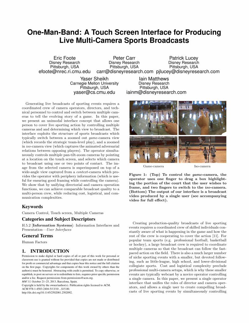
Game-camera Iso-camera
Figure 1: (Top) To control the game-camera, theoperator uses one finger to drag a box highlight-ing the portion of the court that the user wishes toframe, and two fingers to switch to the iso-camera.(Bottom) The output of our interface is a broadcastvideo produced by a single user (see accompanyingvideo for full effect).
Creating production-quality broadcasts of live sportingevents requires a coordinated crew of skilled individuals con-stantly aware of what is happening in the game and how therest of the crew is cooperating to cover the action [11]. Forpopular team sports (e.g. professional football, basketballor hockey), a large broadcast crew is required to coordinatemultiple cameras so that the broadcast can follow the fast-paced action on the field. There is also a much larger numberof niche sporting events with a smaller, but devoted follow-ing, such as little-league, high school, and lower-divisionalcollegiate sports. Cost and logistical complexity precludeprofessional multi-camera setups, which is why these smallerevents are typically webcast by a novice operator controllinga single camera. In this paper, we present a single operatorinterface that unifies the roles of director and camera oper-ators, and allows a single user to create compelling broad-casts of live sporting events by simultaneously controlling
and switching between multiple pan-tilt-zoom (PTZ) cam-eras.
The interface exploits the particular structure of focus andcontext between the different roles on a sports broadcastproduction crew. As live sport is fast moving and highlyvariable, there is a necessity for the interface to include bothspatial and temporal contexts. In a typical setup, one cam-era operator controls the game-camera, which maintains awide, zoomed-out shot to capture the team-level action. Asecond camera operator controls the isolated-camera (or iso-camera), which captures the emotion and drama of the playusing a zoomed-in view for close-ups of players, coaches,or fans. Both camera operators focus on their viewfinderto ensure they have well composed shots. Simultaneously,their periphery vision gives them context of how the playis unfolding, which allows them to follow the action. Thedirector relies on a bank of live monitors in a control roomto select a series of camera angles to best focus on what ishappening in the game. The director is in continual dialoguewith the camera operators to get particular shots which willhelp place the action in context of the story the director istrying to tell. Thus, for a high-quality live broadcast to beobtained, the communication and understanding of instruc-tion between the director and camera operators has to bevery clear, which is hard to get achieve with an inexperi-enced team.
Our One-Man-Band (OMB) interface unifies the roles ofdirector, game-camera operator, and iso-camera operatorinto an unimodal interface that allows one operator to pro-duce a compelling broadcast of a sporting event. Our in-terface combines focus and context by superimposing videofeeds from multiple robotic pan-tilt-zoom cameras onto videofrom a stationary fish-eye context-camera that captures theentire playing area (see Figure 1). The cameras are pre-cisely calibrated and share a common vantage point. Theoverlay of the broadcast camera resembles a viewfinder, andthe static context-camera mimics periphery vision. The usercontrols the game-camera by dragging the highlighted over-lay to a new area of the touch screen using a single finger.To cut to the iso-camera, the user places a second finger onthe screen. The view from the iso-camera is then displayed,and the iso-camera can be controlled in a similar fashion bydragging both fingers. To cut back to the game-camera, theuser lifts one finger (so that only one finger is in contactwith the touch screen) and the superimposed image returnsto the game-camera. Thus, the interface focuses the user’sattention on one of the camera roles at a time, while si-multaneously providing live spatiotemporal context of thegame, allowing the user to make timely cuts from one cam-era to the other, so that the evolving storyline of the gameis captured in the broadcast1.
We compare our touch interface concept against a tra-ditional three-person crew, with two joystick operators forthe game- and iso-cameras, and one director responsible forswitching between views. To determine if there is any signif-icant difference between the two approaches, we conductedtwo user studies and a perception study comparing the twomethods. For the perception study, the users were asked to
1In terms of a high-definition (HD) live broadcast, croppingthe iso-camera view from the game-camera is not a reason-able option as the resolution will be substantially lower, andthe iso-camera would be constrained to be taken from onlywithin the confines of the game-camera view.
evaluate the two methods against three criteria: (1) actionfollowing: the quality of individual camera control, (2) ap-propriateness of cuts: the quality of cuts between cameras,and (3) overall quality: the quality of the final broadcastfootage. In addition to the perception studies, we also car-ried out quantitative analyses which numerically shows howsimilar the approaches are in terms of the broadcast gener-ated.
2. RELATED WORKInteractive applications often require users to interact with
more information than the screen can display. The Focus +Context interface scheme, introduced in the seminal workof Sarkar et al. [15] on fisheye lenses, enables users to in-teract with different level of details. More recently, Pietrigaet al. [12] investigated a general framework for lenses thathelped users in the navigation of large scenes, while Cock-burn et al. [4] presented a general survey on Focus + Con-text techniques. We can apply a Focus + Context analogyto sport broadcasting with camera operators providing highresolution content through multiple view points. The di-rector then requires an overview of all the video content inrealtime and uses available visual information to decide thefocus (i.e., select the appropriate camera viewpoint). Oursystem builds upon the Focus + Context interface scheme toprovide both an overview of the area covered by the camerasand to enable the user to dynamically set the current areaof interest.
Another approach is to use computer vision to automatethe selection of current viewpoint. Some applications pro-pose to remove the user from the decision process in thecontext of sport broadcasting [2, 13]. Compared to our sys-tem, which is generalizable to many sports, these approachesare often tailored specifically to a single sport. For example,Ariki et al. [2] proposed a system for producing a fully au-tomated broadcast of a soccer game using computer visionand action recognition. Their application did not run in re-altime, meaning the broadcast could only be generated as apost-processed recording rather than a live event.
Some methods have placed control of the broadcast in thehands of the viewer, instead of automating the broadcast.For example in [10], Matthews proposed a system allowingthe viewer of a sporting event to select between multiplecamera views, eliminating the need for a director, thoughstill requiring the use of human operators to control each ofthe cameras. Free-Viewpoint Television [18] eliminated theneed for camera operators with a system that uses an arrayof cameras to synthesize a view from any angle. Althoughthis approach requires neither a director nor the use of anycamera operators, the overhead involved in setting up thecamera array is not suited for the low-budget scenario thatwe target with our system.
In the more general category of remote camera control, Liuet al. [9] proposed a system which, similar to the method pro-posed here, made use of a controllable pan-tilt-zoom cameraplus a wider-angle view to provide the context. In this sys-tem, the views of both the context camera and the pan-tilt-zoom camera were displayed to the user on separate screens.The user would select a region to view by drawing a boxon the context camera view, and the pan-tilt-zoom cam-era would position itself to view that region. Although ourmethod makes similar use of a wider context camera forhelping the user select a view, the “region-selecting” method
in [9] requires the user to draw a new box each time theywant to move the camera, and to continuously switch be-tween the context and pan-tilt-zoom views. By contrast,our system displays both views on a single screen, and al-lows the user to drag the pan-tilt-zoom display region torespond more easily to a more fast-paced and dynamic sce-nario such as a sporting event. Our system also allows forthe control of multiple cameras, while [9] uses only a singlecamera.
Other work on camera control has focused on the con-trol of virtual cameras in a graphics or animation environ-ment [3, 5, 16, 19, 20]. A common premise in each of thesemethods is that it is easier to control a camera by specifyingthe desired framing than it is to manipulate the degrees offreedom of the camera directly. For example, Singh et al. [16]presented a controller for manipulating a virtual camera byspecifying the vanishing points and horizon line of the cam-era view. Manipulating the camera perspective would thenaffect the focal length, center of projection, or pose of thecamera. Drucker and Zeltzer [5] proposed an interface forspecifying constraints on the camera view, such as the sizeand/or position of one or more objects. Both [8] and [17]present a method for camera control by directly selecting anobject for the camera to point at, and [17] also allowed usersto control a virtual camera in a 3D graphics environment byspecifying the framing of two points in the virtual world.In [6], Gleicher and Witkin proposed a virtual camera con-troller in which the user could “pin” one or more objects tosub-regions of the camera view, and using these constraintsto solve for the time derivatives of the camera parameters.
A touch interface for controlling a remote camera was pro-posed by Kuzuoka et al. [8] as part of a system for remotecollaboration. In this system, the camera view appearedon a touch screen display, and touching a displayed objectwould cause the camera to automatically center on that ob-ject. The interface also supported velocity control by hold-ing a finger on the display. The velocity and direction of theresulting camera motion directly corresponded to the direc-tion and distance from the touch position to the center ofthe display. However, the proposed controller did not allowfor the use of multiple cameras, and did not provide a widercontext view as our system does.
Other methods for making robotic camera control moreintuitive have been proposed as well. Aiono et al. proposed arobotic camera that could be controlled by head movements,to be used by a doctor during surgical procedures [1]. Ruiet al [14] proposed a system for remote viewing of meetingsthat used a 360 degree panorama view of the meeting room.Users would control a virtual pan/tilt camera that croppedthe panorama to view only the portion that the user wantedto look at.
3. INTERFACE DESCRIPTIONMany elements for achieving simultaneous focus and con-
text are common to both camera operation task (game- andiso-camera), so we describe these shared aspects first. A sta-tionary context-camera with a fish-eye lens is used to displaythe entire area of play. The video from the active camera(either the game-camera or iso-camera) is superimposed ontop of the context image in its correct location so that itappears as an inset on the context-camera view. To focus
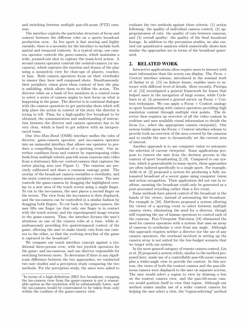
Figure 2: There are three ways to control the gamecamera from our interface. (Top Row) Touching alocation at any point outside of the game-camerahighlight box causes the camera to center on thatlocation. (Middle Row) Touching and dragging anypoint inside of the game-camera box will move thecamera relative to its current position. (BottomRow) Touching the screen and then immediatelyreleasing will also center the game camera on thepoint of contact, whether or not the user touchedthe screen inside the game-camera box.
the user’s attention on the active camera, the image of thecontext camera is desaturated, and the superimposed im-age of the broadcast camera image is outlined with a solidcolor border (yellow for the game-camera and red for theiso-camera). All three cameras are calibrated and share thesame vantage point. The views from all cameras are dis-played and updated live.
Game-Camera Control.The game-camera operator is responsible for covering the
general action of the sporting match. For ball sports, thismeans that the ball should always be in shot as well as mostof the players. If the game has a goal (or basket) then thisshould also be included, if possible. To accomplish these ob-jectives, the game-camera operator maintains a wide-angleshot. As this view contains most of the information of in-terest, it will be used the majority of the time.
The three methods for controlling the game-camera areillustrated in Figure 2. In the first method (top row), theuser touches a location on the screen outside the currentview and the highlighted box containing the game-cameraview will move to the center of that location. We call thisthe “tap-to-center” approach. The second method (middlerow) or“click-and-drag”method is activated by touching thescreen at any location inside the game-camera highlightedbox and maintaining contact. With this form of control, theuser drags his/her finger across the screen, and the gamecamera moves as needed to to maintain the same positionrelative to the user’s finger. The third method of control(bottom row) is to touch and immediately release a locationon the screen. The game-camera will center to that location,
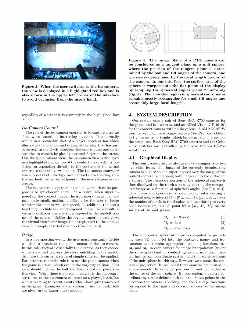
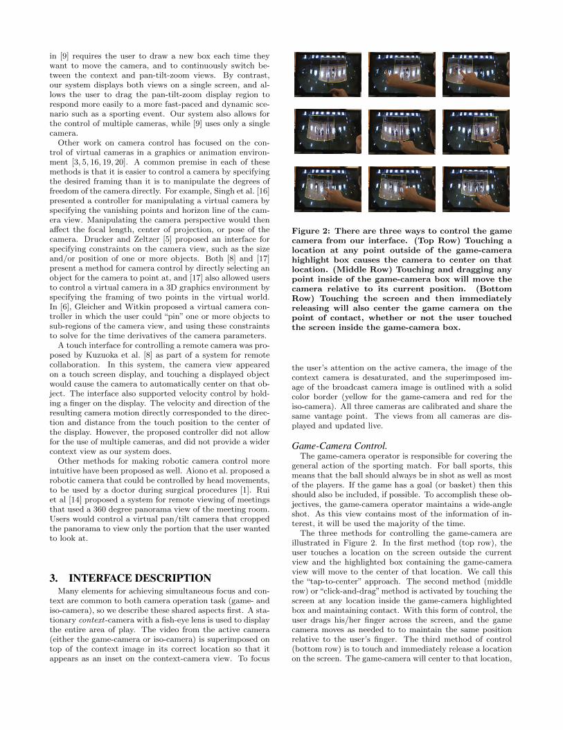
Figure 3: When the user switches to the iso-camera,the view is displayed in a highlighted red box and isalso shown in the upper left corner of the interfaceto avoid occlusion from the user’s hand.
regardless of whether it is currently in the highlighted boxor not.
Iso-Camera Control.The role of the iso-camera operator is to capture close-up
shots when something interesting happens. This normallyresults in a zoomed-in shot of a player, coach or fan whichillustrates the emotion and drama of the play that has justoccurred. In the OMB interface, the user chooses and oper-ates the iso-camera by placing a second finger on the screen.Like the game-camera view, the iso-camera view is displayedin a highlighted box on top of the context view, with its po-sition corresponding directly to the position of the actualcamera so that the views line up. The iso-camera controlleralso supports both the tap-to-center and click-and-drag con-trol methods, using the midpoint of the user’s fingers as ref-erence.
The iso-camera is operated at a high zoom, since its pur-pose is to get close-up shots. As a result, when superim-posed on the context image, the iso-camera image may ap-pear quite small, making it difficult for the user to judgewhether the shot is well composed. In addition, the user’shand may occlude the superimposed image. As a result, avirtual viewfinder image is superimposed in the top-left cor-ner of the screen. Unlike the regular superimposed view,the virtual viewfinder image is not registered to the contextview but simply inserted over top (See Figure 3).
Usage.In a live sporting event, the user must constantly decide
whether to broadcast the game-camera or the iso-camera.In this role, they are essentially the director, as they choosewhich view best conveys the story unfolding in the match.To make this easier, a series of simple rules can be applied.For instance, the main rule is to use the game-camera whenthe game is active, which occurs the majority of time. Thisview should include the ball and the majority of players inthis view. When there is a break in play, it is then appropri-ate to cut to the iso-camera centered on a player/coach/fanwho is reacting to recent events which have just transpiredin the game. Examples of the system in use for basketballare given in the Experiments section.
Ω
φ
θ
θ
φ
Ω
Figure 4: The image plane of a PTZ camera canbe considered as a tangent plane on a unit sphere,where the position of the tangent plane is deter-mined by the pan and tilt angles of the camera, andthe size is determined by the focal length (zoom) ofthe camera. In our interface, the surface area of thesphere is warped onto the flat plane of the displayby sampling the spherical angles φ and θ uniformly(right). The viewable region in spherical coordinatesremains mostly rectangular for small tilt angles andreasonably large focal lengths.
4. SYSTEM DESCRIPTIONOur system uses a pair of Sony BRC-Z700 cameras for
the game- and iso-cameras, and an Allied Vision GE 1910Cfor the context-camera with a fisheye lens. A 3M M2256PWtouch screen monitor is connected to a Mac Pro, and a Gefen4x1 video switcher toggles which broadcast signal is sent tothe computer. Both Sony BRC-Z700 cameras and the Gefenvideo switcher are controlled by the Mac Pro via RS-232serial links.
4.1 Graphical DisplayThe touch screen display always shows a composite of two
live video feeds. The image of the currently broadcastingcamera is aligned to and superimposed over the image of thecontext-camera by mapping both images onto the surface ofa sphere. The necessary portion of the spherical surface isthen displayed on the touch screen by plotting the compos-ited image as a function of spherical angles (see Figure 4).This unwarping operation is computed by interpolating aspherical area of interest Ω = [θmin, θmax]× [φmin, φmax] overthe number of pixels in the display, and associating to everypixel location (u, v) a 3D point M = [Mx,My,Mz] on thesurface of the unit sphere
Mx = sin θ cosφ (1)
My = sinφ (2)
Mz = cos θ cosφ. (3)
The composited spherical image is computed by project-ing each 3D point M into the context-, game- and iso-cameras to determine appropriate sampling locations mc,mg and mi; in each camera for image interpolation (wherethe subscripts stand for context, game and iso). Each cam-era has its own coordinate system, and the reference frameof the unit sphere is arbitrary. However, we assume the cen-ters of projection (lenses) of all three cameras are located inapproximately the same 3D position C, and define this asthe centre of the unit sphere. By convention, a camera co-ordinate system is defined such that the z axis points in thedirection the camera is looking, and the x and y directionscorrespond to the right and down directions on the imageplane.
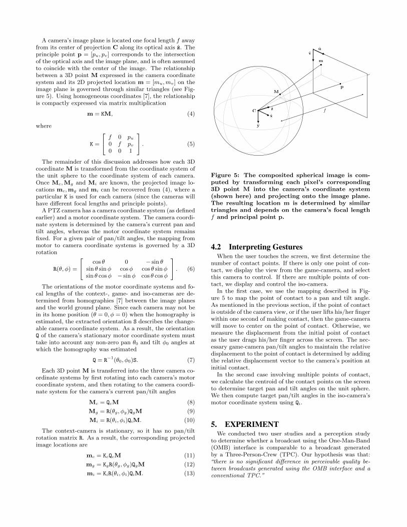
A camera’s image plane is located one focal length f awayfrom its center of projection C along its optical axis z. Theprinciple point p = [pu, pv] corresponds to the intersectionof the optical axis and the image plane, and is often assumedto coincide with the center of the image. The relationshipbetween a 3D point M expressed in the camera coordinatesystem and its 2D projected location m = [mu,mv] on theimage plane is governed through similar triangles (see Fig-ure 5). Using homogeneous coordinates [7], the relationshipis compactly expressed via matrix multiplication
m = KM, (4)
where
K =
f 0 pu0 f pv0 0 1
. (5)
The remainder of this discussion addresses how each 3Dcoordinate M is transformed from the coordinate system ofthe unit sphere to the coordinate system of each camera.Once Mc,Mg and Mi are known, the projected image lo-cations mc,mg and mi can be recovered from (4), where aparticular K is used for each camera (since the cameras willhave different focal lengths and principle points).
A PTZ camera has a camera coordinate system (as definedearlier) and a motor coordinate system. The camera coordi-nate system is determined by the camera’s current pan andtilt angles, whereas the motor coordinate system remainsfixed. For a given pair of pan/tilt angles, the mapping frommotor to camera coordinate systems is governed by a 3Drotation
R(θ, φ) =
cos θ 0 − sin θsin θ sinφ cosφ cos θ sinφsin θ cosφ − sinφ cos θ cosφ
. (6)
The orientations of the motor coordinate systems and fo-cal lengths of the context-, game- and iso-cameras are de-termined from homographies [7] between the image planesand the world ground plane. Since each camera may not bein its home position (θ = 0, φ = 0) when the homography isestimated, the extracted orientation S describes the change-able camera coordinate system. As a result, the orientationQ of the camera’s stationary motor coordinate system musttake into account any non-zero pan θ0 and tilt φ0 angles atwhich the homography was estimated
Q = R−1(θ0, φ0)S. (7)
Each 3D point M is transferred into the three camera co-ordinate systems by first rotating into each camera’s motorcoordinate system, and then rotating to the camera coordi-nate system for the camera’s current pan/tilt angles
Mc = QcM (8)
Mg = R(θg, φg)QgM (9)
Mi = R(θi, φi)QiM. (10)
The context-camera is stationary, so it has no pan/tiltrotation matrix R. As a result, the corresponding projectedimage locations are
mc = KcQcM (11)
mg = KgR(θg, φg)QgM (12)
mi = KiR(θi, φi)QiM. (13)
C
p
x
z
y
m
uv
M
f
Figure 5: The composited spherical image is com-puted by transforming each pixel’s corresponding3D point M into the camera’s coordinate system(shown here) and projecting onto the image plane.The resulting location m is determined by similartriangles and depends on the camera’s focal lengthf and principal point p.
4.2 Interpreting GesturesWhen the user touches the screen, we first determine the
number of contact points. If there is only one point of con-tact, we display the view from the game-camera, and selectthis camera to control. If there are multiple points of con-tact, we display and control the iso-camera.
In the first case, we use the mapping described in Fig-ure 5 to map the point of contact to a pan and tilt angle.As mentioned in the previous section, if the point of contactis outside of the camera view, or if the user lifts his/her fingerwithin one second of making contact, then the game-camerawill move to center on the point of contact. Otherwise, wemeasure the displacement from the initial point of contactas the user drags his/her finger across the screen. The nec-essary game-camera pan/tilt angles to maintain the relativedisplacement to the point of contact is determined by addingthe relative displacement vector to the camera’s position atinitial contact.
In the second case involving multiple points of contact,we calculate the centroid of the contact points on the screento determine target pan and tilt angles on the unit sphere.We then compute target pan/tilt angles in the iso-camera’smotor coordinate system using Qi.
5. EXPERIMENTWe conducted two user studies and a perception study
to determine whether a broadcast using the One-Man-Band(OMB) interface is comparable to a broadcast generatedby a Three-Person-Crew (TPC). Our hypothesis was that:“there is no significant difference in perceivable quality be-tween broadcasts generated using the OMB interface and aconventional TPC.”
A
B
Wednesday, September 21, 2011
A
B
Wednesday, September 21, 2011
(a)
(b)
A
B
Wednesday, September 21, 2011
Robotic Camera II(Iso-Camera)
Robotic Camera I(Game-Camera)
Fixed Camera
Projector
Footage Projected onto a Wall
Processing UnitOne-Man-Band Touch
Interface
One-Man-Band: Game- and Iso-Camera
Operator & Director
Game-Camera Joystick
Iso-Camera Joystick Camera Switcher
Game-Camera Operator
Iso-Camera Operator
DirectorBroadcast Output
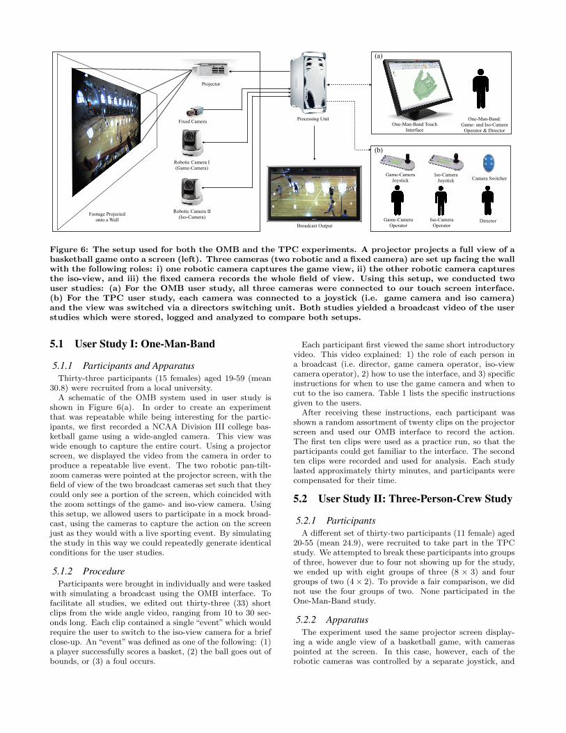
Figure 6: The setup used for both the OMB and the TPC experiments. A projector projects a full view of abasketball game onto a screen (left). Three cameras (two robotic and a fixed camera) are set up facing the wallwith the following roles: i) one robotic camera captures the game view, ii) the other robotic camera capturesthe iso-view, and iii) the fixed camera records the whole field of view. Using this setup, we conducted twouser studies: (a) For the OMB user study, all three cameras were connected to our touch screen interface.(b) For the TPC user study, each camera was connected to a joystick (i.e. game camera and iso camera)and the view was switched via a directors switching unit. Both studies yielded a broadcast video of the userstudies which were stored, logged and analyzed to compare both setups.
5.1 User Study I: One-Man-Band
5.1.1 Participants and ApparatusThirty-three participants (15 females) aged 19-59 (mean
30.8) were recruited from a local university.A schematic of the OMB system used in user study is
shown in Figure 6(a). In order to create an experimentthat was repeatable while being interesting for the partic-ipants, we first recorded a NCAA Division III college bas-ketball game using a wide-angled camera. This view waswide enough to capture the entire court. Using a projectorscreen, we displayed the video from the camera in order toproduce a repeatable live event. The two robotic pan-tilt-zoom cameras were pointed at the projector screen, with thefield of view of the two broadcast cameras set such that theycould only see a portion of the screen, which coincided withthe zoom settings of the game- and iso-view camera. Usingthis setup, we allowed users to participate in a mock broad-cast, using the cameras to capture the action on the screenjust as they would with a live sporting event. By simulatingthe study in this way we could repeatedly generate identicalconditions for the user studies.
5.1.2 ProcedureParticipants were brought in individually and were tasked
with simulating a broadcast using the OMB interface. Tofacilitate all studies, we edited out thirty-three (33) shortclips from the wide angle video, ranging from 10 to 30 sec-onds long. Each clip contained a single “event” which wouldrequire the user to switch to the iso-view camera for a briefclose-up. An “event” was defined as one of the following: (1)a player successfully scores a basket, (2) the ball goes out ofbounds, or (3) a foul occurs.
Each participant first viewed the same short introductoryvideo. This video explained: 1) the role of each person ina broadcast (i.e. director, game camera operator, iso-viewcamera operator), 2) how to use the interface, and 3) specificinstructions for when to use the game camera and when tocut to the iso camera. Table 1 lists the specific instructionsgiven to the users.
After receiving these instructions, each participant wasshown a random assortment of twenty clips on the projectorscreen and used our OMB interface to record the action.The first ten clips were used as a practice run, so that theparticipants could get familiar to the interface. The secondten clips were recorded and used for analysis. Each studylasted approximately thirty minutes, and participants werecompensated for their time.
5.2 User Study II: Three-Person-Crew Study
5.2.1 ParticipantsA different set of thirty-two participants (11 female) aged
20-55 (mean 24.9), were recruited to take part in the TPCstudy. We attempted to break these participants into groupsof three, however due to four not showing up for the study,we ended up with eight groups of three (8 × 3) and fourgroups of two (4 × 2). To provide a fair comparison, we didnot use the four groups of two. None participated in theOne-Man-Band study.
5.2.2 ApparatusThe experiment used the same projector screen display-
ing a wide angle view of a basketball game, with cameraspointed at the screen. In this case, however, each of therobotic cameras was controlled by a separate joystick, and
1. The game-camera view (or wide-angled view) shouldcapture a third of the court.
2. When the ball is moving from one side of the court tothe other, frame the player with the ball on the lastthird of the frame (i.e., lead to where the play is going).
3. When the player with the ball arrives into the attack-ing third of the court, make sure that the hoop, back-board, and the player with the ball are all in view.
4. Cut to the iso-camera to get a close up of the playerwho either: (a) scored a basket, (b) touched the ballbefore it went out, (c) committed a foul or got fouled.If you are not sure who it was, give your best guess.
Table 1: The rules given to the participants for us-ing the game-camera, iso-camera and when to cutbetween these two views.
the views from the two broadcast cameras were each dis-played on their own monitor. A video switcher was used tochange the view, which was used by the director. A diagramof the setup is given in Figure 6(b).
5.2.3 ProcedureEach group was shown the same introductory video as the
previous study which explained the roles of production crewmember (game-camera operator, iso-camera operator, anddirector), in addition to what each person should do whenan “event” occurs. Using the setup depicted in Figure 6(b),one participant of the group was assigned to operate thegame-camera, another to the iso-camera and the third tothe role of the director. The director decided which view tobroadcast and would give instructions to the other cameraoperators if desired.
For this study, a random assortment of forty clips wereplayed on the projector screen for each group. As with theOMB study, the first ten were used as a practice run anddata was not recorded. For the eight groups of three, duringthe practice run, the three participants rotated positionsevery three clips (leaving four clips for the last rotation),so that everyone was able to practice each role. Data wasrecorded for the last thirty (30) clips shown.
5.3 Perception Study: Method and Results
5.3.1 ParticipantsTo gauge what naive observers thought of the resulting
broadcasts that came from either the OMB and TPC userstudies, thirty-one participants (12 females) aged 18-54 (mean24.8) were recruited from a local university. None of theseparticipants were used in either of the previous user studies.
5.3.2 ApparatusEach participant viewed the broadcast videos from the
OMB and TPC user studies. Two perception studies wereconducted. The first used a computer program to display thevideos and had three sliders underneath the viewing windowwhich were used to indicate the viewer’s ratings (i.e., 1-5rating scale). The second study was to compare OMB and
TPC videos generated for the same basketball clip, whichwere displayed side-by-side. A single slider underneath thevideos was used to indicate preference, and a text box couldbe used to record comments.
5.3.3 ProcedureEach participant was shown an assortment of twenty recorded
clips which were randomized each time. Ten were recordedby users in the OMB study, and ten from the TPC study.The clips were shown in random order, and participantsrated each clip on a scale from 1 to 5 in three categories:
1. Overall quality,
2. Appropriateness of cuts, and
3. Game-camera smoothness.
Participants were shown examples of “good” and “bad” clipsfor each category before beginning the study. These exam-ples were based on the opinion of an independent expert whodid not know which interface was used.
For the second part of the study, participants viewed pairsof clips side by side. Both recordings were of the same gameevent, with one clip being taken from the OMB interface andthe other from the TPC setup. Participants then selectedwhich recording they thought was better at capturing theevent.
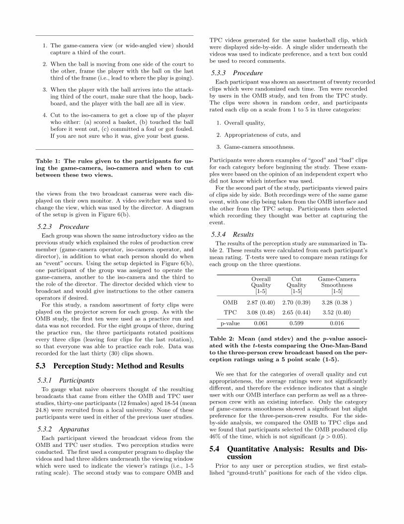
5.3.4 ResultsThe results of the perception study are summarized in Ta-
ble 2. These results were calculated from each participant’smean rating. T-tests were used to compare mean ratings foreach group on the three questions.
Overall Cut Game-CameraQuality Quality Smoothness
[1-5] [1-5] [1-5]
OMB 2.87 (0.40) 2.70 (0.39) 3.28 (0.38 )
TPC 3.08 (0.48) 2.65 (0.44) 3.52 (0.40)
p-value 0.061 0.599 0.016
Table 2: Mean (and stdev) and the p-value associ-ated with the t-tests comparing the One-Man-Bandto the three-person crew broadcast based on the per-ception ratings using a 5 point scale (1-5).
We see that for the categories of overall quality and cutappropriateness, the average ratings were not significantlydifferent, and therefore the evidence indicates that a singleuser with our OMB interface can perform as well as a three-person crew with an existing interface. Only the categoryof game-camera smoothness showed a significant but slightpreference for the three-person-crew results. For the side-by-side analysis, we compared the OMB to TPC clips andwe found that participants selected the OMB produced clip46% of the time, which is not significant (p > 0.05).
5.4 Quantitative Analysis: Results and Dis-cussion
Prior to any user or perception studies, we first estab-lished “ground-truth” positions for each of the video clips.
The ground-truth positions were determined on a frame-by-frame basis for each clip using the rules given in Table 1.These rules define a “correct” way to film each clip [11]. Theground truth camera positions were generated according tothese same rules; however, to eliminate the possibility ofhuman error, we did not record the ground truth positionsin realtime from a human camera operator. Instead, westepped through each of the 33 sequences frame-by-frame,and determined the “text-book” camera position and selec-tion for each frame. Although there is subjectivity in deter-mining how “good” a broadcast is, we can use these resultsto get a relative indication on how close both interfaces areto a baseline broadcast.
After both user studies were conducted, we compared theposition logs from both the OMB and TPC to our groundtruth data. By comparing ground truth camera positionsto those recorded by the user studies, we obtained somequantitative sense of how well users performed against anideal broadcast.
Correct Camera Average AverageSelection Pan Error Tilt Error
[%] [] []
OMB 79.01 (4.65) 5.17 (1.03) 1.17 (0.24)
TPC 73.69 (10.87) 4.51 (0.99) 1.48 (0.44)
p-value 0.015 0.011 <0.001
Table 3: Mean (and stdev) and the p-value associ-ated with the t-tests comparing the OMB and theTPC to the ground-truth broadcast for: 1) the aver-age number of frames the user selected the correctcamera, 2) the average pan error per user, and 3) theaverage tilt error per user. Statistically significantresults are highlighted in bold typeface.
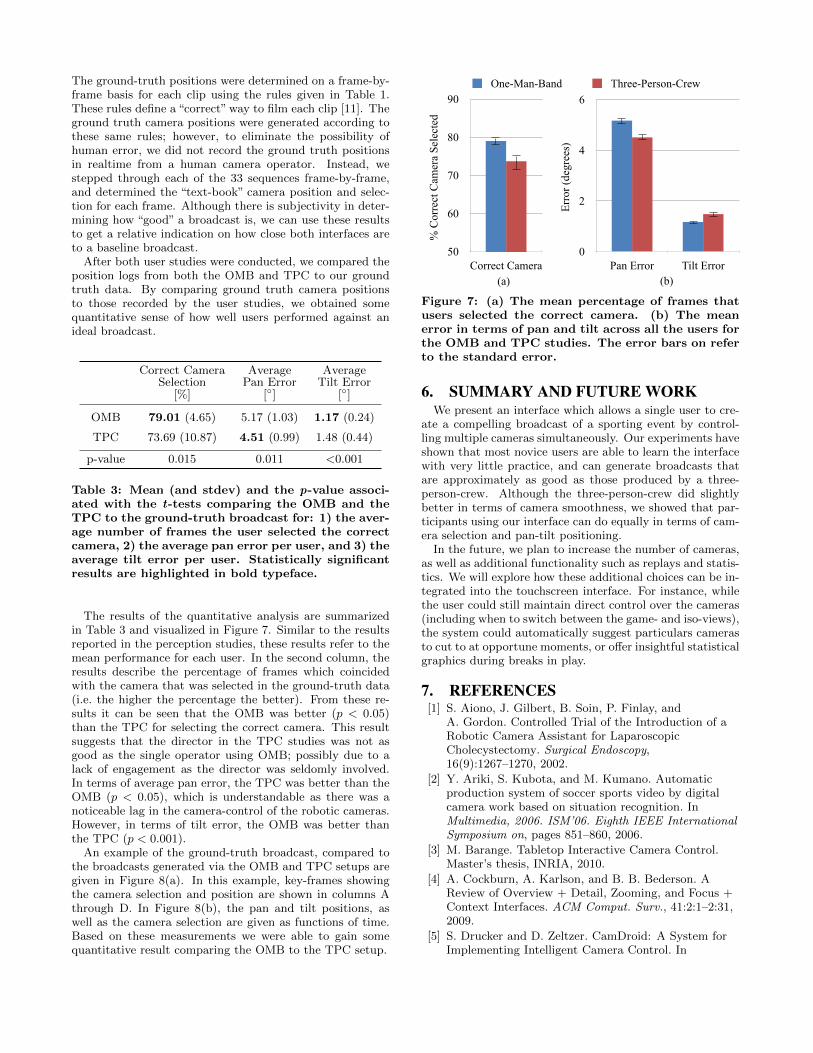
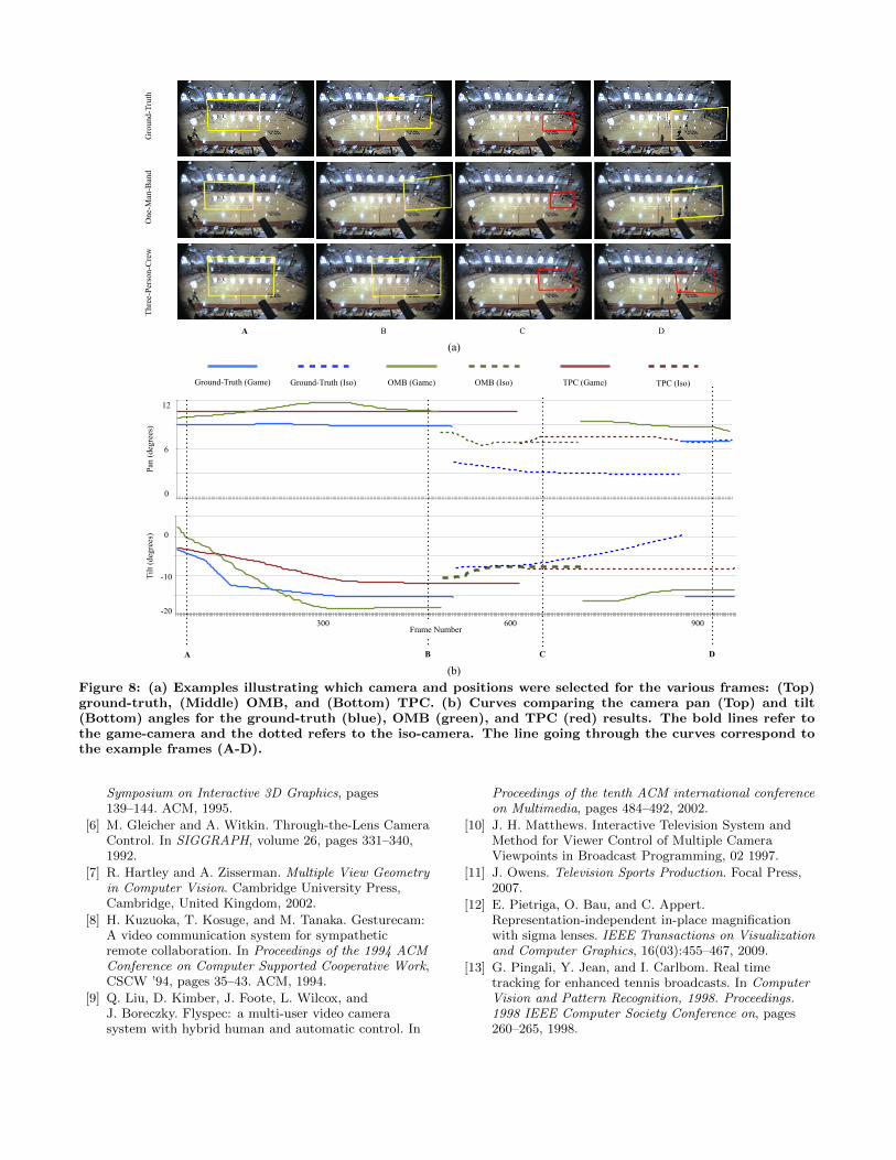
The results of the quantitative analysis are summarizedin Table 3 and visualized in Figure 7. Similar to the resultsreported in the perception studies, these results refer to themean performance for each user. In the second column, theresults describe the percentage of frames which coincidedwith the camera that was selected in the ground-truth data(i.e. the higher the percentage the better). From these re-sults it can be seen that the OMB was better (p < 0.05)than the TPC for selecting the correct camera. This resultsuggests that the director in the TPC studies was not asgood as the single operator using OMB; possibly due to alack of engagement as the director was seldomly involved.In terms of average pan error, the TPC was better than theOMB (p < 0.05), which is understandable as there was anoticeable lag in the camera-control of the robotic cameras.However, in terms of tilt error, the OMB was better thanthe TPC (p < 0.001).
An example of the ground-truth broadcast, compared tothe broadcasts generated via the OMB and TPC setups aregiven in Figure 8(a). In this example, key-frames showingthe camera selection and position are shown in columns Athrough D. In Figure 8(b), the pan and tilt positions, aswell as the camera selection are given as functions of time.Based on these measurements we were able to gain somequantitative result comparing the OMB to the TPC setup.
One-Man-Band Three-Person-Crew
50
60
70
80
90
Correct Camera
% C
orre
ct C
amer
a Se
lect
ed
(a)
0
2
4
6
Pan Error Tilt Error
Erro
r (de
gree
s)
(b)
Figure 7: (a) The mean percentage of frames thatusers selected the correct camera. (b) The meanerror in terms of pan and tilt across all the users forthe OMB and TPC studies. The error bars on referto the standard error.
6. SUMMARY AND FUTURE WORKWe present an interface which allows a single user to cre-
ate a compelling broadcast of a sporting event by control-ling multiple cameras simultaneously. Our experiments haveshown that most novice users are able to learn the interfacewith very little practice, and can generate broadcasts thatare approximately as good as those produced by a three-person-crew. Although the three-person-crew did slightlybetter in terms of camera smoothness, we showed that par-ticipants using our interface can do equally in terms of cam-era selection and pan-tilt positioning.
In the future, we plan to increase the number of cameras,as well as additional functionality such as replays and statis-tics. We will explore how these additional choices can be in-tegrated into the touchscreen interface. For instance, whilethe user could still maintain direct control over the cameras(including when to switch between the game- and iso-views),the system could automatically suggest particulars camerasto cut to at opportune moments, or offer insightful statisticalgraphics during breaks in play.
7. REFERENCES[1] S. Aiono, J. Gilbert, B. Soin, P. Finlay, and
A. Gordon. Controlled Trial of the Introduction of aRobotic Camera Assistant for LaparoscopicCholecystectomy. Surgical Endoscopy,16(9):1267–1270, 2002.
[2] Y. Ariki, S. Kubota, and M. Kumano. Automaticproduction system of soccer sports video by digitalcamera work based on situation recognition. InMultimedia, 2006. ISM’06. Eighth IEEE InternationalSymposium on, pages 851–860, 2006.
[3] M. Barange. Tabletop Interactive Camera Control.Master’s thesis, INRIA, 2010.
[4] A. Cockburn, A. Karlson, and B. B. Bederson. AReview of Overview + Detail, Zooming, and Focus +Context Interfaces. ACM Comput. Surv., 41:2:1–2:31,2009.
[5] S. Drucker and D. Zeltzer. CamDroid: A System forImplementing Intelligent Camera Control. In
900600300!"#
!$#
#
A B C D
!"
#"
$"
%"
&"
'!"
'#"
'$"
!"#$
!%&$
!%#$
!&$
#$
&$
Ground Truth, Camera 1 (Game)
Ground Truth, Camera 2 (Iso)
One Man Band, Camera 1 (Game)
One Man Band, Camera 2 (Iso)
Joystick, Camera 1 (Game)
Joystick, Camera 2 (Iso)
A B C D A B C D
#%&'$"
A B C D
A B C D
Ground-Truth (Game) Ground-Truth (Iso) OMB (Game) OMB (Iso) TPC (Iso)TPC (Game)
Frame Number
Tilt
(deg
rees
)Pa
n (d
egre
es)
Gro
und-
Trut
hO
ne-M
an-B
and
Thre
e-Pe
rson
-Cre
w
0
6
12
-20
-10
0
(a)
(b)Figure 8: (a) Examples illustrating which camera and positions were selected for the various frames: (Top)ground-truth, (Middle) OMB, and (Bottom) TPC. (b) Curves comparing the camera pan (Top) and tilt(Bottom) angles for the ground-truth (blue), OMB (green), and TPC (red) results. The bold lines refer tothe game-camera and the dotted refers to the iso-camera. The line going through the curves correspond tothe example frames (A-D).
Symposium on Interactive 3D Graphics, pages139–144. ACM, 1995.
[6] M. Gleicher and A. Witkin. Through-the-Lens CameraControl. In SIGGRAPH, volume 26, pages 331–340,1992.
[7] R. Hartley and A. Zisserman. Multiple View Geometryin Computer Vision. Cambridge University Press,Cambridge, United Kingdom, 2002.
[8] H. Kuzuoka, T. Kosuge, and M. Tanaka. Gesturecam:A video communication system for sympatheticremote collaboration. In Proceedings of the 1994 ACMConference on Computer Supported Cooperative Work,CSCW ’94, pages 35–43. ACM, 1994.
[9] Q. Liu, D. Kimber, J. Foote, L. Wilcox, andJ. Boreczky. Flyspec: a multi-user video camerasystem with hybrid human and automatic control. In
Proceedings of the tenth ACM international conferenceon Multimedia, pages 484–492, 2002.
[10] J. H. Matthews. Interactive Television System andMethod for Viewer Control of Multiple CameraViewpoints in Broadcast Programming, 02 1997.
[11] J. Owens. Television Sports Production. Focal Press,2007.
[12] E. Pietriga, O. Bau, and C. Appert.Representation-independent in-place magnificationwith sigma lenses. IEEE Transactions on Visualizationand Computer Graphics, 16(03):455–467, 2009.
[13] G. Pingali, Y. Jean, and I. Carlbom. Real timetracking for enhanced tennis broadcasts. In ComputerVision and Pattern Recognition, 1998. Proceedings.1998 IEEE Computer Society Conference on, pages260–265, 1998.
[14] Y. Rui, A. Gupta, and J. J. Cadiz. Viewing MeetingsCaptured by an Omni-directional Camera. InProceedings of the SIGCHI Conference on HumanFactors in Computing Systems, pages 450–457, 2001.
[15] M. Sarkar and M. H. Brown. Graphical Fisheye Views.Commun. ACM, 37:73–83, 1994.
[16] K. Singh, C. Grimm, and N. Sudarsanam. The IBar:A Perspective Based Camera Widget. In Proceedingsof the 17th annual ACM symposium on User interfacesoftware and technology, UIST ’04, pages 95–98. ACM,2004.
[17] P. S. Strauss, R. C. Zeleznik, and A. S. Forsberg. TwoPointer Input For 3D Interaction. In Proceedings ofthe 1997 Symposium on Interactive 3D Graphics,pages 115–120, 1997.
[18] M. Tanimoto. Free-viewpoint television. In Image andGeometry Processing for 3-D Cinematography,volume 5 of Geometry and Computing, pages 53–76.Springer Berlin Heidelberg, 2010.
[19] R. Turner, F. Balaguer, E. Gobbetti, andD. Thalmann. Physically-Based Interactive CameraMotion Control Using 3D Input Devices. In ScientificVisualization of Physical Phenomena, pages 135–145,1991.
[20] R. C. Zeleznik and A. S. Forsberg. UniCam - 2DGestural Camera Controls for 3D Environments, 1999.