one stage gas burners - ching-ye.com.t gs.pdf · the riello 40 gs series of one stage gas burners,...
TRANSCRIPT
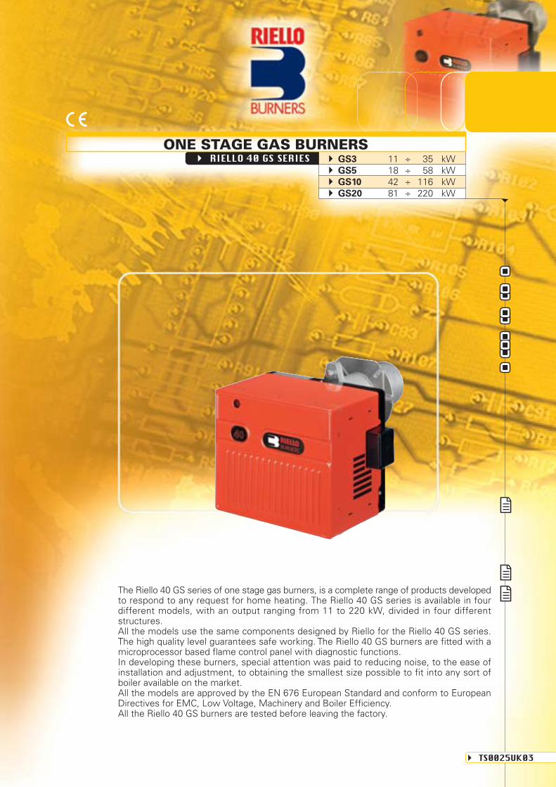
The Riello 40 GS series of one stage gas burners, is a complete range of products developedto respond to any request for home heating. The Riello 40 GS series is available in fourdifferent models, with an output ranging from 11 to 220 kW, divided in four differentstructures.All the models use the same components designed by Riello for the Riello 40 GS series.The high quality level guarantees safe working. The Riello 40 GS burners are fitted with amicroprocessor based flame control panel with diagnostic functions.In developing these burners, special attention was paid to reducing noise, to the ease ofinstallation and adjustment, to obtaining the smallest size possible to fit into any sort ofboiler available on the market.All the models are approved by the EN 676 European Standard and conform to EuropeanDirectives for EMC, Low Voltage, Machinery and Boiler Efficiency.All the Riello 40 GS burners are tested before leaving the factory.
TS0025UK03
ONE STAGE GAS BURNERSRIELLO 40 GS SERIES GS3 11 ÷ 35 kW
GS5 18 ÷ 58 kWGS10 42 ÷ 116 kWGS20 81 ÷ 220 kW
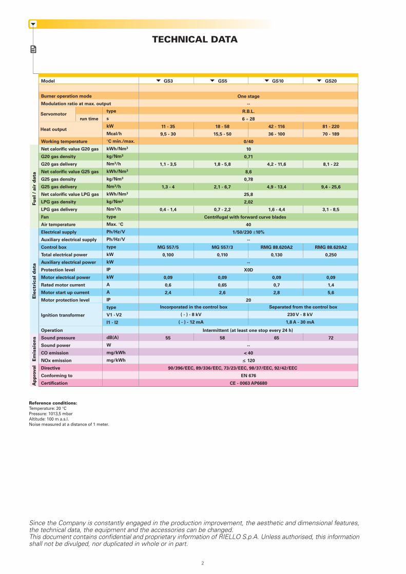
TECHNICAL DATAFu
el /
air
dat
aE
lect
rica
l d
ata
Em
issi
on
sA
ppro
val
Model
Burner operation mode
Modulation ratio at max. output
run time
Working temperature
Net calorific value G20 gas
G20 gas density
G20 gas delivery
Net calorific value G25 gas
G25 gas density
G25 gas delivery
Net calorific value LPG gas
LPG gas density
LPG gas delivery
Fan
Air temperature
Electrical supply
Auxiliary electrical supply
Control box
Total electrical power
Auxiliary electrical power
Protection level
Motor electrical power
Rated motor current
Motor start up current
Motor protection level
Ignition transformer
Operation
Sound pressure
Sound power
CO emission
NOx emission
Directive
Conforming to
Certification
Servomotortype
s
kW
Mcal/h
°C min./max.
kWh/Nm3
kg/Nm3
Nm3/h
kWh/Nm3
kg/Nm3
Nm3/h
kWh/Nm3
kg/Nm3
Nm3/h
type
Max. °C
Ph/Hz/V
Ph/Hz/V
type
kW
kW
IP
kW
A
A
IP
type
V1 - V2
I1 - I2
dB(A)
W
mg/kWh
mg/kWh
Heat output
One stage
--
R.B.L.
6 ÷ 28
11 - 35 18 - 58 42 - 116 81 - 220
9,5 - 30 15,5 - 50 36 - 100 70 - 189
0/40
10
0,71
1,1 - 3,5 1,8 - 5,8 4,2 - 11,6 8,1 - 22
8,6
0,78
1,3 - 4 2,1 - 6,7 4,9 - 13,4 9,4 - 25,6
25,8
2,02
0,4 - 1,4 0,7 - 2,2 1,6 - 4,4 3,1 - 8,5
Centrifugal with forward curve blades
40
1/50/230 ±10%
--
MG 557/5 MG 557/3 RMG 88.620A2 RMG 88.620A2
0,100 0,110 0,130 0,250
--
X0D
0,09 0,09 0,09 0,09
0,6 0,65 0,7 1,4
2,4 2,6 2,8 5,6
20
Intermittent (at least one stop every 24 h)
55 58 65 72
--
< 40
≤ 120
90/396/EEC, 89/336/EEC, 73/23/EEC, 98/37/EEC, 92/42/EEC
EN 676
CE - 0063 AP6680
GS3 GS5 GS10 GS20
Since the Company is constantly engaged in the production improvement, the aesthetic and dimensional features,the technical data, the equipment and the accessories can be changed.This document contains confidential and proprietary information of RIELLO S.p.A. Unless authorised, this informationshall not be divulged, nor duplicated in whole or in part.
Reference conditions:Temperature: 20 °CPressure: 1013,5 mbarAltitude: 100 m a.s.l.Noise measured at a distance of 1 meter.
Incorporated in the control box
( - ) - 8 kV
( - ) - 12 mA
Separated from the control box
230 V - 8 kV
1,8 A - 30 mA
2
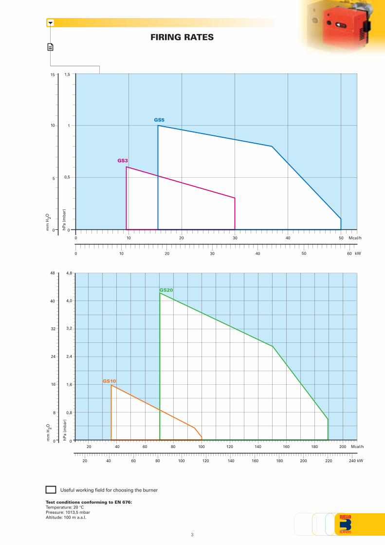
FIRING RATES
Test conditions conforming to EN 676:Temperature: 20 °CPressure: 1013,5 mbarAltitude: 100 m a.s.l.
Useful working field for choosing the burner
0
0,5
kW
0
5
10
15
1
1,5
10 30 4020 50
10 20 30 40 50 600
0
0
0,8
40
0
8
16
24
32
1,6
2,4
3,2
4,0
4,848
20 40 60 80 100 120 140 160 180 200
kW4020 60 80 100 120 140 160 180 200 220 240
GS3
GS5
GS10
GS20
hP
a (m
bar
)
mm
H2O
hP
a (m
bar
)
mm
H2O
3
Mcal/h
Mcal/h
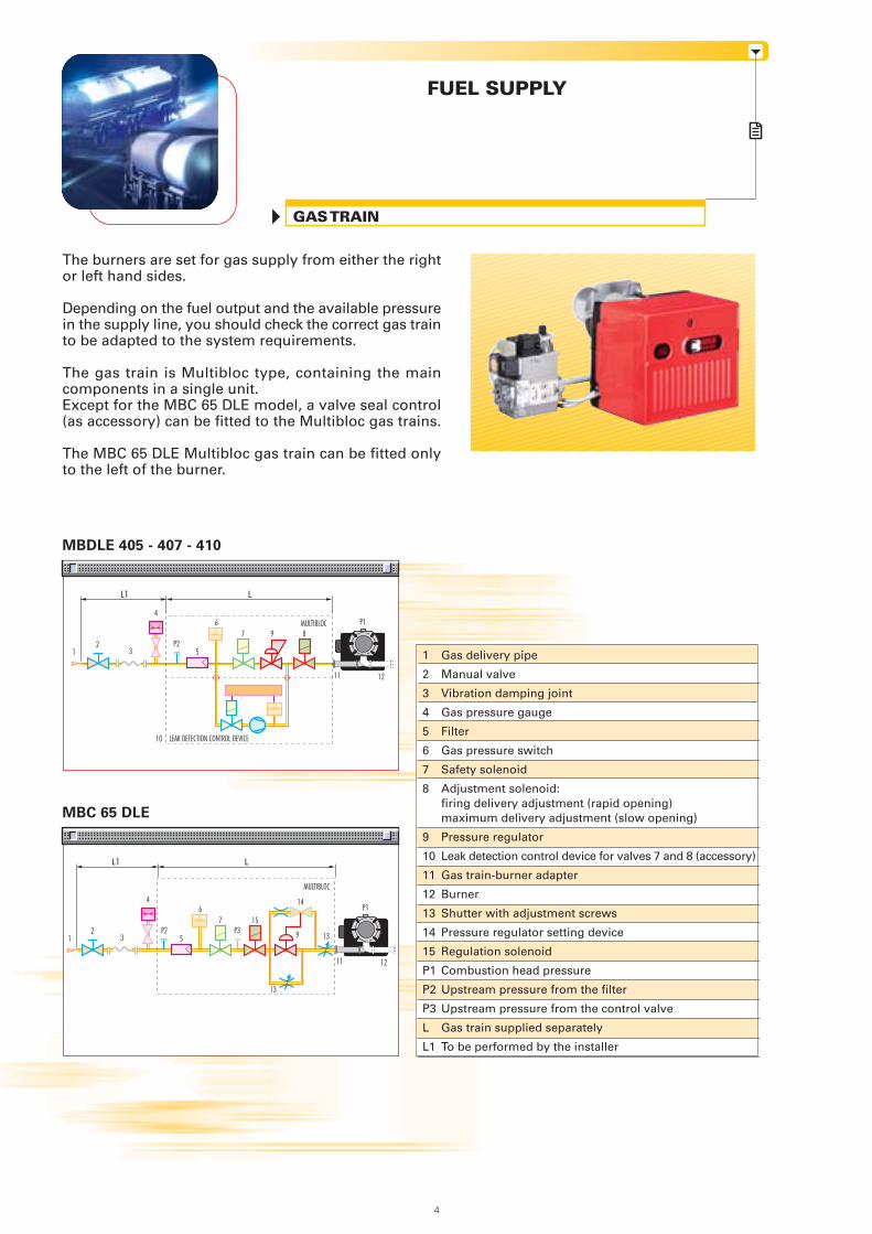
FUEL SUPPLY
GAS TRAIN
The burners are set for gas supply from either the rightor left hand sides.
Depending on the fuel output and the available pressurein the supply line, you should check the correct gas trainto be adapted to the system requirements.
The gas train is Multibloc type, containing the maincomponents in a single unit.Except for the MBC 65 DLE model, a valve seal control(as accessory) can be fitted to the Multibloc gas trains.
The MBC 65 DLE Multibloc gas train can be fitted onlyto the left of the burner.
MBDLE 405 - 407 - 410
L1 L
LEAK DETECTION CONTROL DEVICE
MULTIBLOC
MBC 65 DLE
L1 L
MULTIBLOC
1
2
3
4
5
6
7
8
9
10
11
12
13
14
15
P1
P2
P3
L
L1
Gas delivery pipe
Manual valve
Vibration damping joint
Gas pressure gauge
Filter
Gas pressure switch
Safety solenoid
Adjustment solenoid:firing delivery adjustment (rapid opening)maximum delivery adjustment (slow opening)
Pressure regulator
Leak detection control device for valves 7 and 8 (accessory)
Gas train-burner adapter
Burner
Shutter with adjustment screws
Pressure regulator setting device
Regulation solenoid
Combustion head pressure
Upstream pressure from the filter
Upstream pressure from the control valve
Gas train supplied separately
To be performed by the installer
11
5
96
7 8
12
3
4
P2
10
12
P1
5
67 15
12
3
4
P2 P3
13
13
14
9
11 12
P1
4
MU
LTIB
LOC
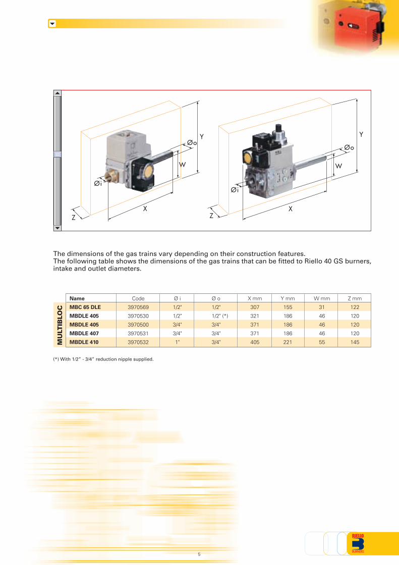
Name
MBC 65 DLE
MBDLE 405
MBDLE 405
MBDLE 407
MBDLE 410
Code
3970569
3970530
3970500
3970531
3970532
Ø i
1/2"
1/2"
3/4"
3/4"
1"
Ø o
1/2"
1/2" (*)
3/4"
3/4"
3/4"
X mm
307
321
371
371
405
Y mm
155
186
186
186
221
Z mm
122
120
120
120
145
W mm
31
46
46
46
55
Y
ZX
W
The dimensions of the gas trains vary depending on their construction features.The following table shows the dimensions of the gas trains that can be fitted to Riello 40 GS burners,intake and outlet diameters.
(*) With 1/2” - 3/4” reduction nipple supplied.
5
Y
ZX
Øi
W
Øi
ØoØo
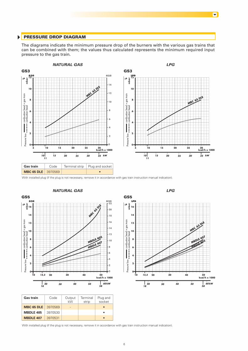
PRESSURE DROP DIAGRAM
The diagrams indicate the minimum pressure drop of the burners with the various gas trains thatcan be combined with them; the values thus calculated represents the minimum required inputpressure to the gas train.
NATURAL GAS LPG
GS3 GS3
NATURAL GAS LPG
GS5 GS5
Gas train
MBC 65 DLE
Code
3970569
Terminal strip Plug and socket
•
Gas train
MBC 65 DLE
MBDLE 405
MBDLE 407
Code
3970569
3970530
3970531
Terminalstrip
Plug andsocket
•
•
•
OutputkW
-
ΔP
com
busti
on h
ead
+ ga
s tra
inco
mbu
stion
hea
dPr
essu
re lo
ssm
ba
r ΔP
com
busti
on h
ead
+ ga
s tra
inco
mbu
stion
hea
dPr
essu
re lo
ssm
ba
r
4
10
6
8
12
kcal/h x 1000
kW
5 10 15 20 25 30
20 3510
2
0
15 25 3011
G20 G25
0
2
6
8
10
12
14
4
MBC 65 D
LE
4
10
6
8
12
kcal/h x 1000
kW
5 10 15 20 25 30
20 3510
2
0
15 25 3011
LPG
MBC 65 DLE
4
10
6
8
12
kcal/h x 1000
kW
10 20 30 50
20 60
2
0
30 40 50
14
16
40
5818
15,5
G20 G25
MBDLE 407MBDLE 405
MBC 65
DLE
4
10
6
8
12
kcal/h x 1000
kW
10 20 30 50
20 60
2
0
30 40 50
14
16
40
5818
15,5
LPG
MBDLE 405MBDLE 407
MBC 65 DLE
22
0
2
6
8
10
12
16
18
20
14
4
ΔP
com
busti
on h
ead
+ ga
s tra
inco
mbu
stion
hea
dPr
essu
re lo
ssm
ba
r ΔP
com
busti
on h
ead
+ ga
s tra
inco
mbu
stion
hea
dPr
essu
re lo
ssm
ba
r
6
With installed plug (if the plug is not necessary, remove it in accordance with gas train instruction manual indication).
With installed plug (if the plug is not necessary, remove it in accordance with gas train instruction manual indication).
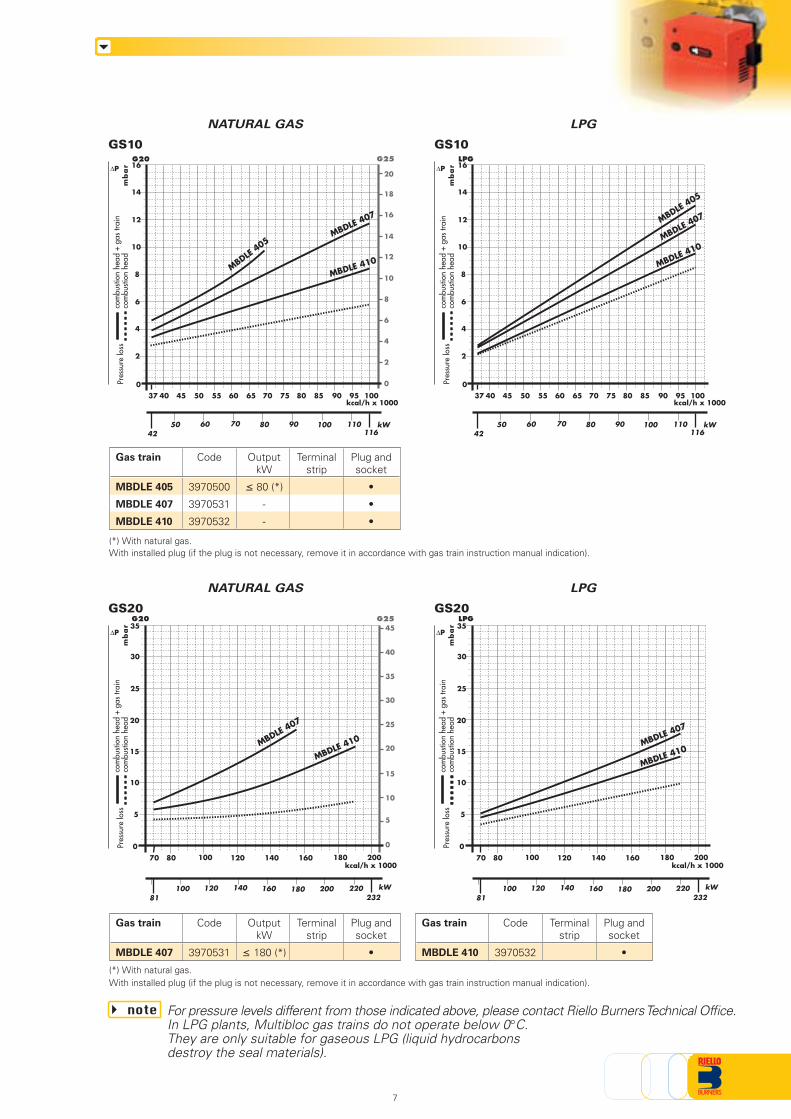
NATURAL GAS LPG
GS10 GS10
NATURAL GAS LPG
GS20 GS20
For pressure levels different from those indicated above, please contact Riello Burners Technical Office.In LPG plants, Multibloc gas trains do not operate below 0°C.They are only suitable for gaseous LPG (liquid hydrocarbonsdestroy the seal materials).
note
Gas train
MBDLE 407
Code
3970531
Terminalstrip
Plug andsocket
•
OutputkW
≤ 180 (*)
Gas train
MBDLE 410
Code
3970532
Terminalstrip
Plug andsocket
•
Gas train
MBDLE 405
MBDLE 407
MBDLE 410
Code
3970500
3970531
3970532
Terminalstrip
Plug andsocket
•
•
•
OutputkW
≤ 80 (*)
-
-
(*) With natural gas.
(*) With natural gas.
ΔP
com
busti
on h
ead
+ ga
s tra
inco
mbu
stion
hea
dPr
essu
re lo
ssm
ba
r
ΔP
com
busti
on h
ead
+ ga
s tra
inco
mbu
stion
hea
dPr
essu
re lo
ssm
ba
r
kcal/h x 1000
kW116
605042
10070 9080 110
G20
MBDLE 410
55 656037 10040 45 50 70 75 80 85 90 95
0
2
8
12
10
16
4
6
14
MBDLE 407
MBDLE 405
kcal/h x 1000
kW116
605042
10070 9080 110
LPG
MBDLE 410
55 656037 10040 45 50 70 75 80 85 90 95
0
2
8
12
10
16
4
6
14
MBDLE 407MBDLE
405
MBDLE 410
kW232
120
0
10081
200
5
10
15
20
25
140 180160 220
kcal/h x 1000100 20080 120 140 18016070
30
35G20 G25
0
5
15
25
30
35
10
40
45
MBDLE 407
MBDLE 410
kW232
120
0
10081
200
5
10
15
20
25
140 180160 220
kcal/h x 1000100 20080 120 140 18016070
30
35LPG
MBDLE 407
G25
0
2
6
8
10
12
16
18
20
14
4
20
7
ΔP
com
busti
on h
ead
+ ga
s tra
inco
mbu
stion
hea
dPr
essu
re lo
ssm
ba
r ΔP
com
busti
on h
ead
+ ga
s tra
inco
mbu
stion
hea
dPr
essu
re lo
ssm
ba
r
With installed plug (if the plug is not necessary, remove it in accordance with gas train instruction manual indication).
With installed plug (if the plug is not necessary, remove it in accordance with gas train instruction manual indication).
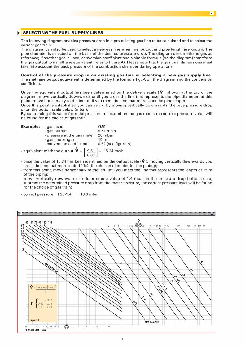
SELECTING THE FUEL SUPPLY LINES
0,1 0,2 0,3 0,4 0,5 0,6 0,7 0,8 1 2 3 4 5 106 20
50 60 10080 200 400 800 1000600
3
69
12152230
45 61 76 95 122 152 V
PRESSURE DROP (mbar)
1 2 3 4 5 6 7 8 10 20 30 40
PIPE DIAMETER
1,4
PIPE LENGTH (m)
1/2
3/4
1"
1" 1/2
6"
1" 1/4
4"
3"2" 1/22"
= Gas output Nmc/h
1 - G20= 0,62 - G25
1,18 - G31{f
V
15,34
Figure A
8
The following diagram enables pressure drop in a pre-existing gas line to be calculated and to select thecorrect gas train.The diagram can also be used to select a new gas line when fuel output and pipe length are known. Thepipe diameter is selected on the basis of the desired pressure drop. The diagram uses methane gas asreference; if another gas is used, conversion coefficient and a simple formula (on the diagram) transformthe gas output to a methane equivalent (refer to figure A). Please note that the gas train dimensions musttake into account the back pressure of the combustion chamber during operations.
Control of the pressure drop in an existing gas line or selecting a new gas supply line.The methane output equivalent is determined by the formula fig. A on the diagram and the conversioncoefficient.
Once the equivalent output has been determined on the delivery scale ( ), shown at the top of thediagram, move vertically downwards until you cross the line that represents the pipe diameter; at thispoint, move horizontally to the left until you meet the line that represents the pipe length.Once this point is established you can verify, by moving vertically downwards, the pipe pressure dropof on the botton scale below (mbar).By subtracting this value from the pressure measured on the gas meter, the correct pressure value willbe found for the choice of gas train.
Example: - gas used G25- gas output 9.51 mc/h- pressure at the gas meter 20 mbar- gas line length 15 m- conversion coefficient 0.62 (see figure A)
- equivalent methane output = 9.51 = 15.34 mc/h0.62
- once the value of 15.34 has been identified on the output scale ( ), moving vertically downwards youcross the line that represents 1" 1/4 (the chosen diameter for the piping);
- from this point, move horizontally to the left until you meet the line that represents the length of 15 mof the piping;
- move vertically downwards to determine a value of 1.4 mbar in the pressure drop botton scale;- subtract the determined pressure drop from the meter pressure, the correct pressure level will be found
for the choice of gas train;
- correct pressure = ( 20-1.4 ) = 18.6 mbar
V
V
V
COMBUSTION HEAD
The combustion head in Riello 40 GS burners is the result of aninnovative design, which allows combustion with low pollutingemissions, while being easy to adapt to all the various types ofboilers and combustion chambers.
Combustion head Flange
Simple adjustment allowsthe internal geometry ofthe combustion head tobe adapted to the burneroutput.
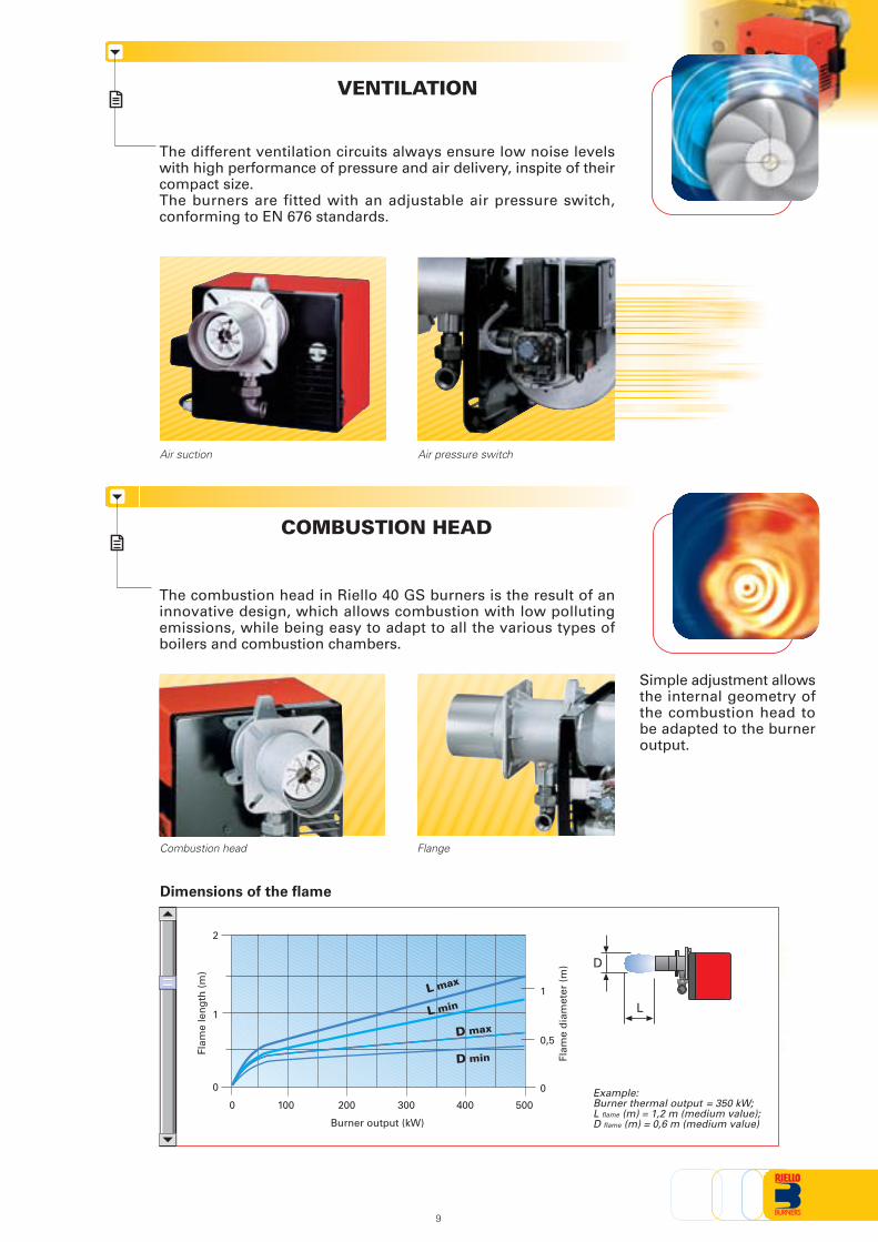
VENTILATION
The different ventilation circuits always ensure low noise levelswith high performance of pressure and air delivery, inspite of theircompact size.The burners are fitted with an adjustable air pressure switch,conforming to EN 676 standards.
Air suction Air pressure switch
Dimensions of the flame
Example:Burner thermal output = 350 kW;L flame (m) = 1,2 m (medium value);D flame (m) = 0,6 m (medium value)Burner output (kW)
Flam
e le
ng
th (
m)
Flam
e d
iam
eter
(m
)
0 200
1
100 300
2
400 500
0 0
0,5
1
D
L
L max
L min
D max
D min
9
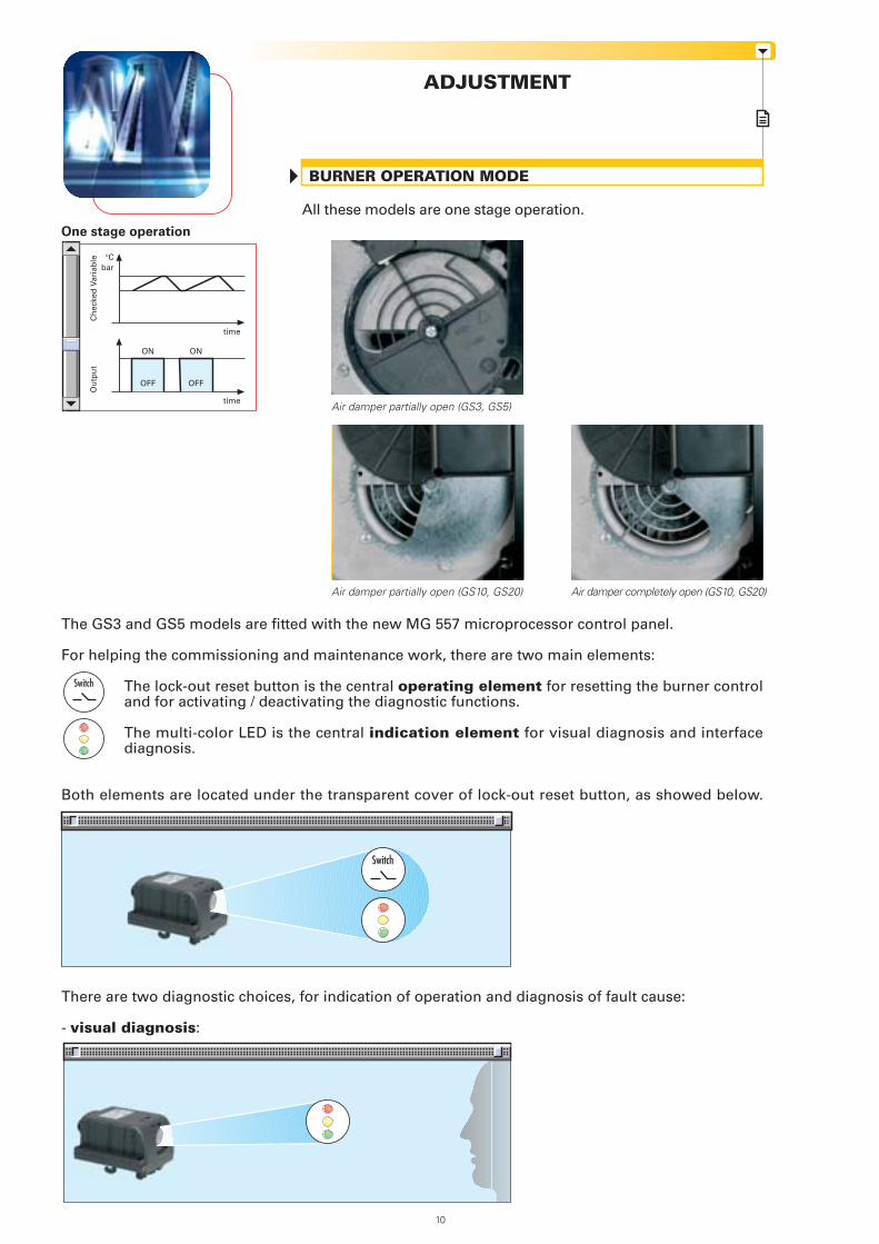
ADJUSTMENT
All these models are one stage operation.
BURNER OPERATION MODE
Air damper partially open (GS3, GS5)
Air damper partially open (GS10, GS20) Air damper completely open (GS10, GS20)
The GS3 and GS5 models are fitted with the new MG 557 microprocessor control panel.
For helping the commissioning and maintenance work, there are two main elements:
The lock-out reset button is the central operating element for resetting the burner controland for activating / deactivating the diagnostic functions.
The multi-color LED is the central indication element for visual diagnosis and interfacediagnosis.
Both elements are located under the transparent cover of lock-out reset button, as showed below.
There are two diagnostic choices, for indication of operation and diagnosis of fault cause:
- visual diagnosis:
Switch
One stage operation
Ou
tpu
tC
hec
ked
Var
iab
le
bar°C
ON
OFF
time
time
ON
OFF
10
Switch
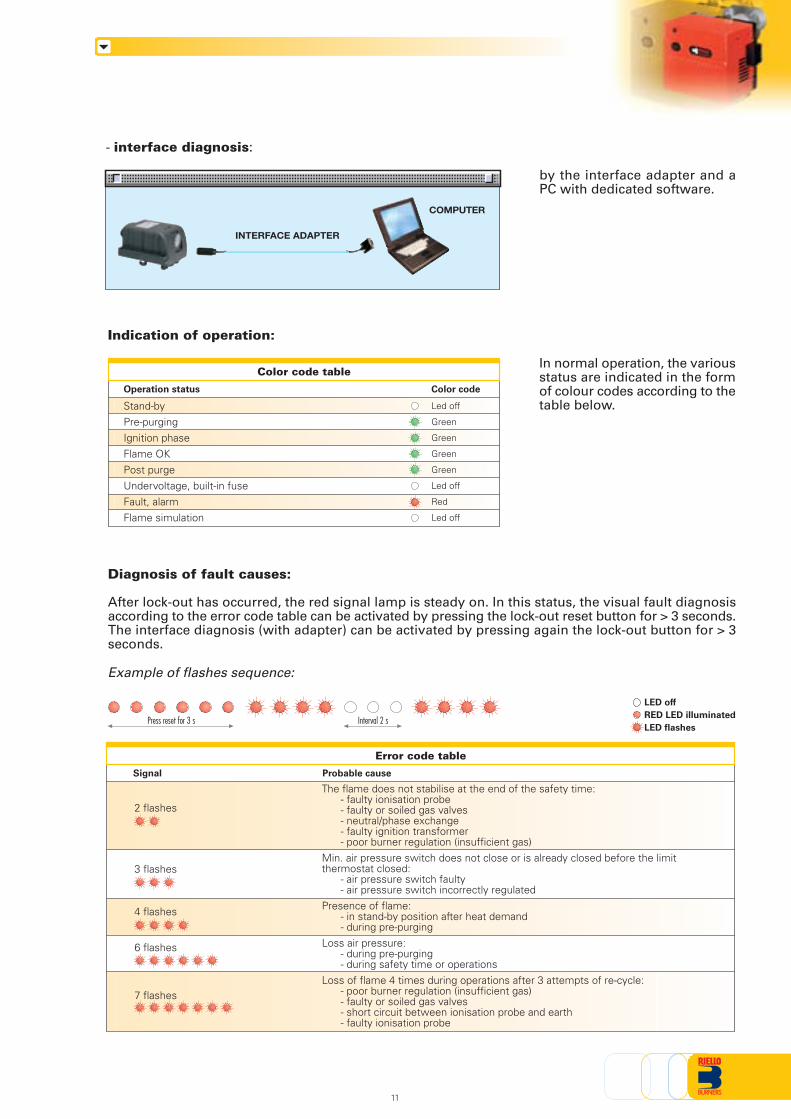
Indication of operation:
In normal operation, the variousstatus are indicated in the formof colour codes according to thetable below.
Diagnosis of fault causes:
After lock-out has occurred, the red signal lamp is steady on. In this status, the visual fault diagnosisaccording to the error code table can be activated by pressing the lock-out reset button for > 3 seconds.The interface diagnosis (with adapter) can be activated by pressing again the lock-out button for > 3seconds.
Example of flashes sequence:
Interval 2 sPress reset for 3 s
Error code table
Probable cause
The flame does not stabilise at the end of the safety time:- faulty ionisation probe- faulty or soiled gas valves- neutral/phase exchange- faulty ignition transformer- poor burner regulation (insufficient gas)
Min. air pressure switch does not close or is already closed before the limitthermostat closed:
- air pressure switch faulty- air pressure switch incorrectly regulated
Presence of flame:- in stand-by position after heat demand- during pre-purging
Loss air pressure:- during pre-purging- during safety time or operations
Loss of flame 4 times during operations after 3 attempts of re-cycle:- poor burner regulation (insufficient gas)- faulty or soiled gas valves- short circuit between ionisation probe and earth- faulty ionisation probe
Signal
2 flashes
3 flashes
4 flashes
6 flashes
7 flashes
COMPUTER
INTERFACE ADAPTER
11
Color code table
Operation status
Stand-byPre-purgingIgnition phaseFlame OKPost purgeUndervoltage, built-in fuseFault, alarmFlame simulation
Color code
Led off
Green
Green
Green
Green
Led off
Red
Led off
LED off
RED LED illuminated
LED flashes
- interface diagnosis:
by the interface adapter and aPC with dedicated software.
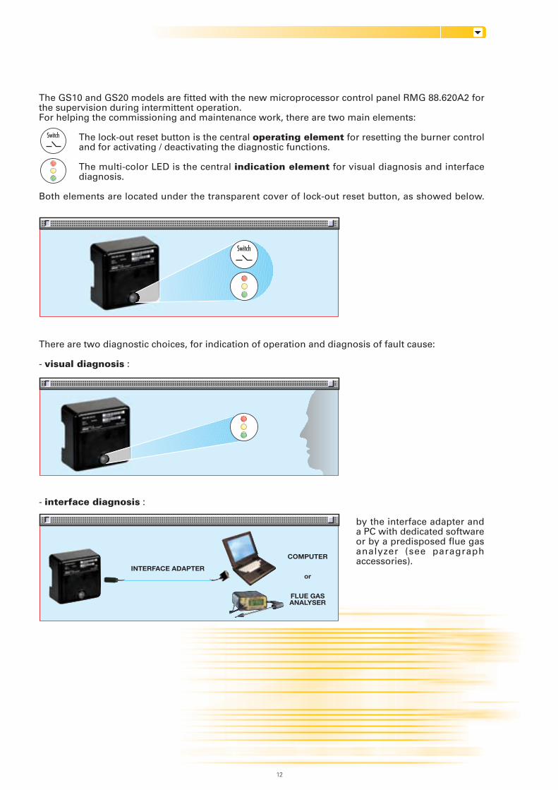
The GS10 and GS20 models are fitted with the new microprocessor control panel RMG 88.620A2 forthe supervision during intermittent operation.For helping the commissioning and maintenance work, there are two main elements:
The lock-out reset button is the central operating element for resetting the burner controland for activating / deactivating the diagnostic functions.
The multi-color LED is the central indication element for visual diagnosis and interfacediagnosis.
Both elements are located under the transparent cover of lock-out reset button, as showed below.
There are two diagnostic choices, for indication of operation and diagnosis of fault cause:
- visual diagnosis :
- interface diagnosis :
by the interface adapter anda PC with dedicated softwareor by a predisposed flue gasanalyzer (see paragraphaccessories).
Switch
COMPUTER
or
FLUE GASANALYSER
INTERFACE ADAPTER
12
Switch
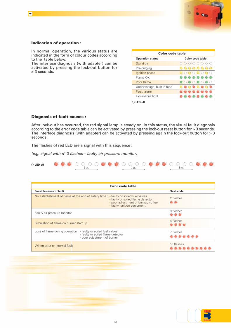
Indication of operation :
In normal operation, the various status areindicated in the form of colour codes accordingto the table below.The interface diagnosis (with adapter) can beactivated by pressing the lock-out button for> 3 seconds.
Error code table
Possible cause of fault
No establishment of flame at the end of safety time : - faulty or soiled fuel valves- faulty or soiled flame detector- poor adjustment of burner, no fuel- faulty ignition equipment
Faulty air pressure monitor
Simulation of flame on burner start up
Loss of flame during operation : - faulty or soiled fuel valves- faulty or soiled flame detector- poor adjustment of burner
Wiring error or internal fault
Flash code
13
Color code table
Operation status
Stand-byPre-purgingIgnition phaseFlame OKPoor flameUndervoltage, built-in fuseFault, alarmExtraneous light
Color code table
LED off
Diagnosis of fault causes :
After lock-out has occurred, the red signal lamp is steady on. In this status, the visual fault diagnosisaccording to the error code table can be activated by pressing the lock-out reset button for > 3 seconds.The interface diagnosis (with adapter) can be activated by pressing again the lock-out button for > 3seconds.
The flashes of red LED are a signal with this sequence :
(e.g. signal with n° 3 flashes – faulty air pressure monitor)
LED off3 sec. 3 sec. 3 sec.
2 flashes
3 flashes
4 flashes
7 flashes
10 flashes
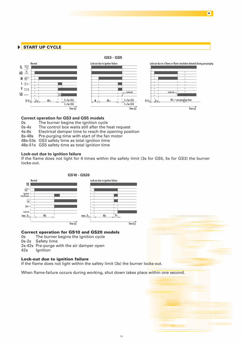
Correct operation for GS10 and GS20 models0s The burner begins the ignition cycle0s-2s Safety time2s-42s Pre-purge with the air damper open42s Ignition
Lock-out due to ignition failureIf the flame does not light within the safety limit (3s) the burner locks-out.
When flame-failure occurs during working, shut down takes place within one second.
START UP CYCLE
Correct operation for GS3 and GS5 models0s The burner begins the ignition cycle0s-4s The control box waits still after the heat request4s-8s Electrical damper time to reach the opening position8s-48s Pre-purging time with start of the fan motor48s-53s GS3 safety time as total ignition time48s-51s GS5 safety time as total ignition time
Lock-out due to ignition failureIf the flame does not light for 4 times within the safety limit (3s for GS5, 5s for GS3) the burnerlocks-out.
TRM
GS3 - GS5
GS10 - GS20
Time (s) Time (s)
M
TL
MIV
SO
Time (s)
AD
Time (s) Time (s)
max. 2s 40s
Ignitiontransformer
Lock-out
40s
Normal Lock-out due to ignition failure
3smax. 2s
Lock-out due to ignition failure
40 s
Normal
3 s for GS55 s for GS3
4 s0÷4 s 40 s 3 s for GS55 s for GS3
8̃s
Lock-out
Lock-out due to a flame or flame simulation detected during pre-purging
4 s0÷4 s
Lock-out
ϑP
M
14
40 s = pre-purging time
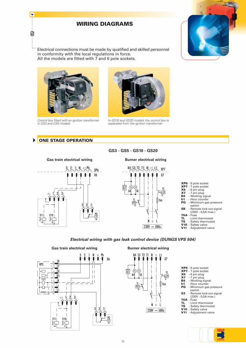
Electrical connections must be made by qualified and skilled personnelin conformity with the local regulations in force.All the models are fitted with 7 and 6 pole sockets.
WIRING DIAGRAMS
Control box fitted with an ignition transformerin GS3 and GS5 models
ONE STAGE OPERATION
GS3 - GS5 - GS10 - GS20
In GS10 and GS20 models the control box isseparated from the ignition transformer
Burner electrical wiringGas train electrical wiring
Burner electrical wiringGas train electrical wiring
XP6 - 6 pole socketXP7 - 7 pole socketX6 - 6 pin plugX7 - 7 pin plugB4 - Working signalh1 - Hour counterPG - Minimum gas pressure
switchSB - Remote lock-out signal
(230V - 0,5A max.)T6A - FuseTL - Limit thermostatTS - Safety thermostatV10 - Safety valveV11 - Adjustment valve
XP6 - 6 pole socketXP7 - 7 pole socketX6 - 6 pin plugX7 - 7 pin plugB4 - Working signalh1 - Hour counterPG - Minimum gas pressure
switchS3 - Remote lock-out signal
(230V - 0,5A max.)T6A - FuseTL - Limit thermostatTS - Safety thermostatV10 - Safety valveV11 - Adjustment valve
15
Electrical wiring with gas leak control device (DUNGS VPS 504)
PTS
T6A
X7XP7
SB
N L
B4 ϑ
B4 S3 T2 N L1T1
TLP ϑ
h1
~230V 50Hz
PPGV10V11
X6
3 2 1
321
XP63 2 N Ph1
PPGV10V11
VPS
B5N
L1
T6
T8T7
X6
3 2 1
321
3 2 N Ph1
PTS
T6A
X7
SB
N L
B4
B4 S3 T2 N L1T1
ϑ
TLP ϑ
h1
~230V 50Hz
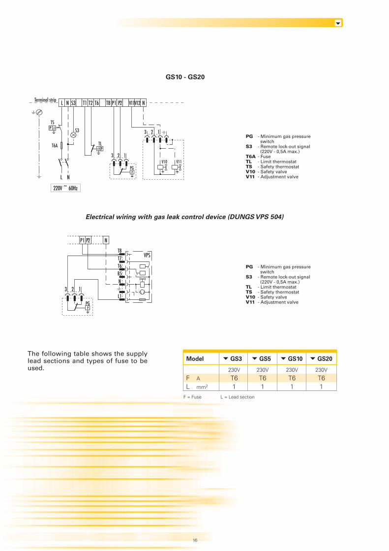
The following table shows the supplylead sections and types of fuse to beused.
GS10 - GS20
PG - Minimum gas pressure switch
S3 - Remote lock-out signal (220V - 0,5A max.)
T6A - FuseTL - Limit thermostatTS - Safety thermostatV10 - Safety valveV11 - Adjustment valve
PG - Minimum gas pressure switch
S3 - Remote lock-out signal (220V - 0,5A max.)
TL - Limit thermostatTS - Safety thermostatV10 - Safety valveV11 - Adjustment valve
16
PTS
TLP
PPG
V10 V11
220V ~ 60Hz
Terminal strip L N S3 T1 T2 P1 NT6 V11P2T8 V12
S3
L N
3 2 1
3 2 1ϑ
ϑT6A
Electrical wiring with gas leak control device (DUNGS VPS 504)
GS3Model
A
mm2
FL
230V
T61
F = Fuse L = Lead section
GS5
230V
T61
GS10
230V
T61
GS20
230V
T61
VPS
B5N
L1
T6
T8T7
PPG
3 2 1
P1 NP2
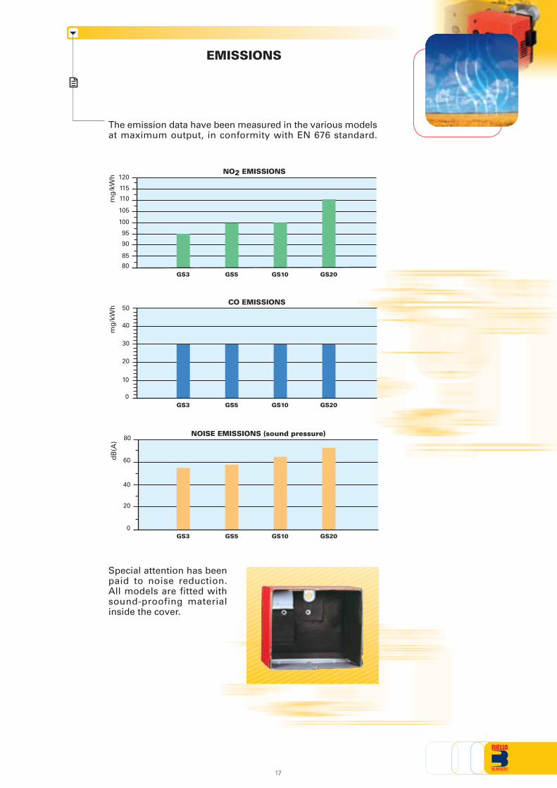
EMISSIONS
Special attention has beenpaid to noise reduction.All models are fitted withsound-proofing materialinside the cover.
NO2 EMISSIONS
mg
/kW
h
80
CO EMISSIONS
mg
/kW
h
0
10
20
30
40
NOISE EMISSIONS (sound pressure)
dB
(A)
0
80
85
90
95
100
105
110
115
50
20
40
60
120
GS3 GS5 GS10 GS20
GS3 GS5 GS10 GS20
GS3 GS5 GS10 GS20
17
The emission data have been measured in the various modelsat maximum output, in conformity with EN 676 standard.
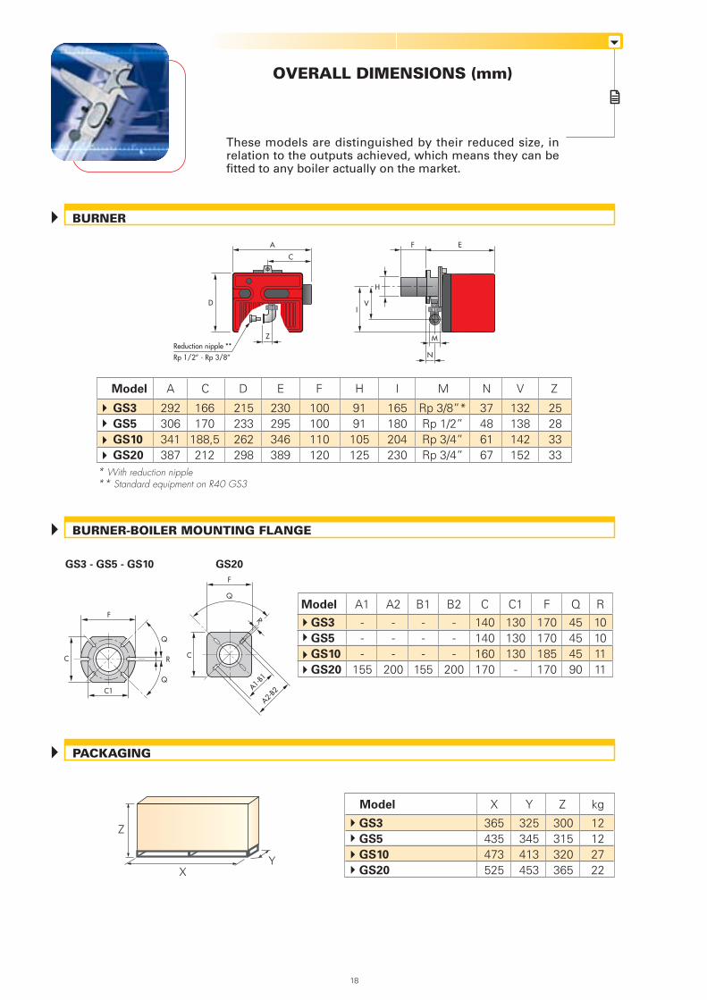
OVERALL DIMENSIONS (mm)
These models are distinguished by their reduced size, inrelation to the outputs achieved, which means they can befitted to any boiler actually on the market.
X
Z
Y
PACKAGING
BURNER
BURNER-BOILER MOUNTING FLANGE
365435473525
325345413453
12122722
300315320365
Model
GS3
GS5
GS10
GS20
X Y kgZ
GS3 - GS5 - GS10
* With reduction nipple** Standard equipment on R40 GS3
F
C R
C1
18
A
D
C
Reduction nipple **
Rp 1/2” - Rp 3/8”
F E
IV
M
N
H
Z
Model A C D E
GS3
GS5
GS10
GS20
166170
188,5212
292306341387
230295346389
215233262298
F
100100110120
H
9191105125
I
165180204230
N
37486167
M
Rp 3/8”*Rp 1/2”Rp 3/4”Rp 3/4”
V
132138142152
25283333
Z
GS20
A2-B2
F
C
R
A1-B1
Q
Q
Q
Model
GS3
GS5
GS10
GS20
---
155
A1
---
200
A2
---
155
B1
---
200
B2
130130130
-
C1
45454590
Q
10101111
R
140140160170
C F
170170185170
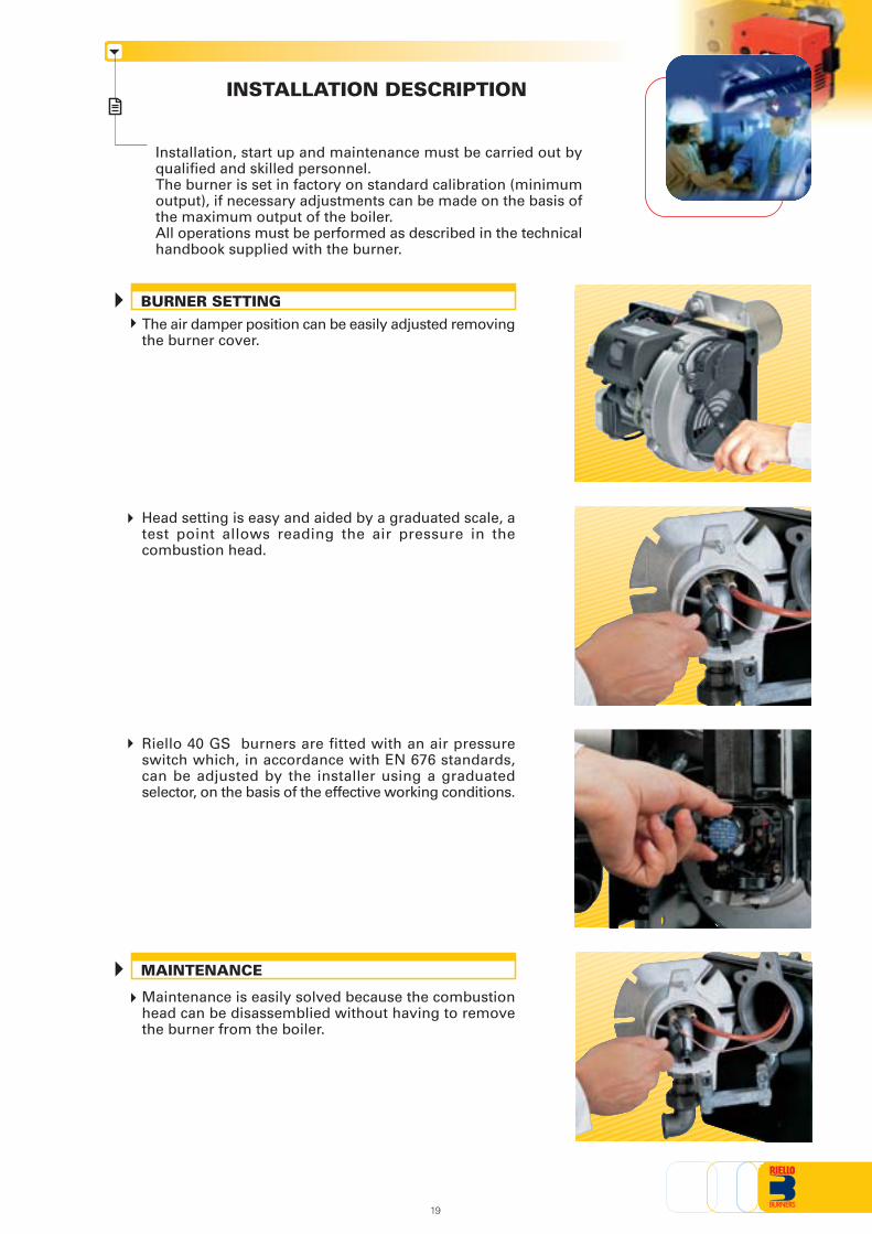
INSTALLATION DESCRIPTION
Installation, start up and maintenance must be carried out byqualified and skilled personnel.The burner is set in factory on standard calibration (minimumoutput), if necessary adjustments can be made on the basis ofthe maximum output of the boiler.All operations must be performed as described in the technicalhandbook supplied with the burner.
The air damper position can be easily adjusted removingthe burner cover.
Head setting is easy and aided by a graduated scale, atest point allows reading the air pressure in thecombustion head.
Riello 40 GS burners are fitted with an air pressureswitch which, in accordance with EN 676 standards,can be adjusted by the installer using a graduatedselector, on the basis of the effective working conditions.
Maintenance is easily solved because the combustionhead can be disassemblied without having to removethe burner from the boiler.
19
BURNER SETTING
MAINTENANCE
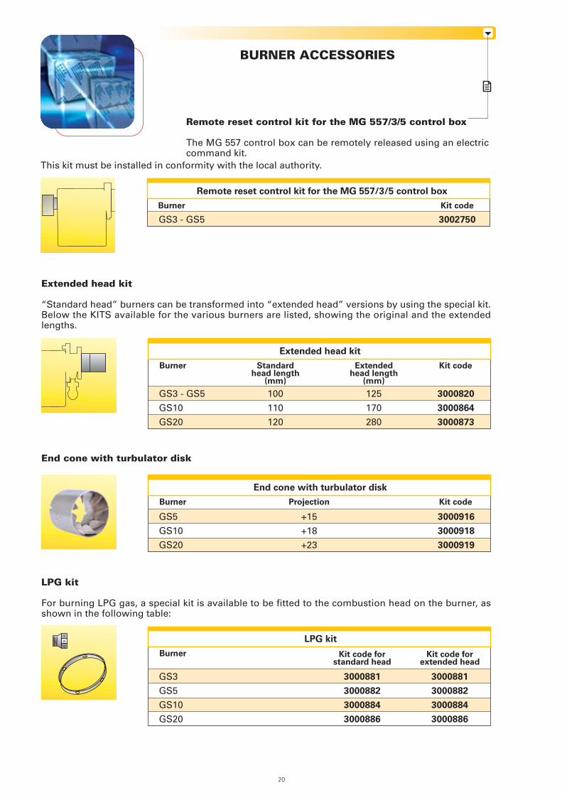
BURNER ACCESSORIES
Remote reset control kit for the MG 557/3/5 control box
The MG 557 control box can be remotely released using an electriccommand kit.
Extended head kit
“Standard head” burners can be transformed into “extended head” versions by using the special kit.Below the KITS available for the various burners are listed, showing the original and the extendedlengths.
End cone with turbulator disk
Kit code
3000916
3000918
3000919
GS5
GS10
GS20
Burner
End cone with turbulator disk
Projection
+15
+18
+23
LPG kit
For burning LPG gas, a special kit is available to be fitted to the combustion head on the burner, asshown in the following table:
GS3
GS5
GS10
GS20
Burner
LPG kit
Kit code
3002750GS3 - GS5
Burner
Remote reset control kit for the MG 557/3/5 control box
This kit must be installed in conformity with the local authority.
3000881
3000882
3000884
3000886
3000881
3000882
3000884
3000886
Kit code forextended head
Kit code forstandard head
Kit code
3000820
3000864
3000873
GS3 - GS5
GS10
GS20
Burner
Extended head kit
Extendedhead length
(mm)
125
170
280
Standardhead length
(mm)
100
110
120
20
Town gas kit
GS3
GS5
GS10
GS20
Burner
Town gas kit
PC interface kit
To connect the flame control panel to a personal computer for the transmission of operation, faultsignals and detailed service information, an interface adapter with PC software are available.
Burner Kit code
3002731
3002719
PC interface kit
GS3 - GS5GS10 - GS20
Kit code
3000888
3000889
3000891
3000893
Ground fault interrupter kit
A “Ground fault interrupter kit” is available as a safety device in case of electrical system fault. It issupplied with burners pin plug.
Burner Kit code
3001180
Ground fault interrupter kit
GS3 - GS5 - GS10 - GS20
7-pin plug kit
If necessary a 7-pin plug kit is available (in packaging of n. 5 pieces).
Burner Kit code
3000945
7-pin plug kit
All models
Continuous ventilation kit for RMG control box
If the burner requires continuous ventilation in the stages without flame, a special kit is available asgiven in the following table.
Burner Kit code
3010094
Continuous ventilation kit for RMG control box
GS10 - GS20
21
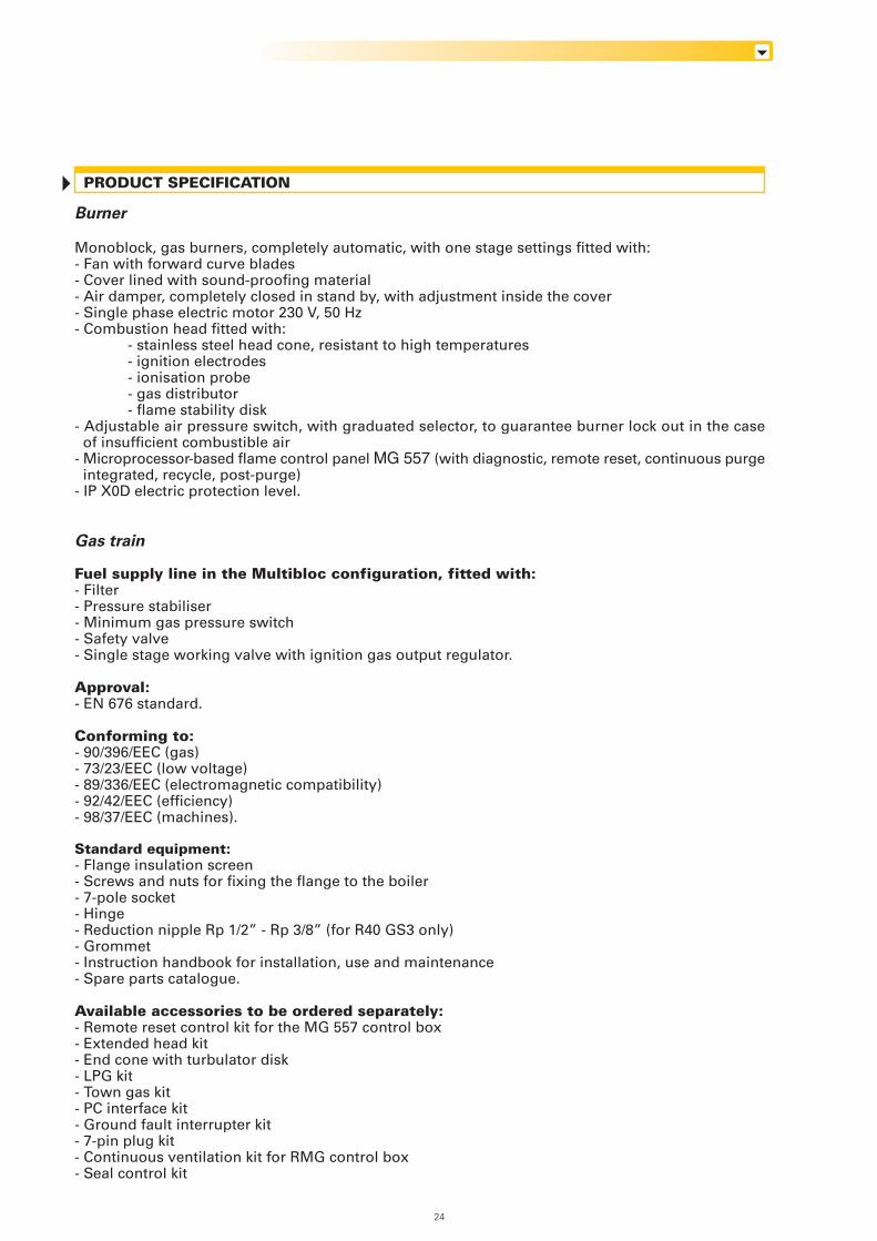
BALANCED FLUE VERSION
Riello 40 GS Balanced Flue version
Kit code
3010123
3010123
3010123
GS5
GS10
GS20
Burner
Seal control kit
Seal control kit
To test the valve seals on the gas train, (except for the model with Multibloc MBC 65 DLE) a special"seal control kit" is available.
GAS TRAIN ACCESSORIES
MBDLE 405 - 407
MBDLE 405 - 407 - 410
MBDLE 407 - 410
Gas train
The R40 series balanced flue gas burner has been specificallydesigned to meet the increasing trend towards the use of balancedflue, otherwise known as room sealed appliances, which avoid thenecessity of having a chimney to discharge the products ofcombustion.
Balanced flue products are completely sealed from the environmentin which they are installed, drawing air for combustion directly fromthe outside, thereby ensuring no unwelcome smells from thecombustion.
As a result of the burner components being completely enclosedthis provides an additional benefit of low sound levels.
This version is available for GS3 and GS5 only.
Overall dimensions (mm)
288
249
96 308
91
22
SPECIFICATION
A special index guides your choice of boiler from thevarious models available in the GS series.Below is a clear and detailed specification descriptionof the product.
AVAILABLE BURNER MODELS
GS3 1/230/50GS5 1/230/50GS10 1/230/50GS20 1/230/50
Size
DESIGNATION OF SERIES
G S
Series: G
3
Fuel : S Natural gas
1/230/50
GS5 1/220/60GS10 1/220/60GS20 1/220/60
23
Electrical supply to the system : 1/230/50 1/230V/50Hz1/220/60 1/220V/60Hz
Burner
Monoblock, gas burners, completely automatic, with one stage settings fitted with:- Fan with forward curve blades- Cover lined with sound-proofing material- Air damper, completely closed in stand by, with adjustment inside the cover- Single phase electric motor 230 V, 50 Hz- Combustion head fitted with:
- stainless steel head cone, resistant to high temperatures- ignition electrodes- ionisation probe- gas distributor- flame stability disk
- Adjustable air pressure switch, with graduated selector, to guarantee burner lock out in the caseof insufficient combustible air
- Microprocessor-based flame control panel MG 557 (with diagnostic, remote reset, continuous purgeintegrated, recycle, post-purge)
- IP X0D electric protection level.
Gas train
Fuel supply line in the Multibloc configuration, fitted with:- Filter- Pressure stabiliser- Minimum gas pressure switch- Safety valve- Single stage working valve with ignition gas output regulator.
Approval:- EN 676 standard.
Conforming to:- 90/396/EEC (gas)- 73/23/EEC (low voltage)- 89/336/EEC (electromagnetic compatibility)- 92/42/EEC (efficiency)- 98/37/EEC (machines).
Standard equipment:- Flange insulation screen- Screws and nuts for fixing the flange to the boiler- 7-pole socket- Hinge- Reduction nipple Rp 1/2” - Rp 3/8” (for R40 GS3 only)- Grommet- Instruction handbook for installation, use and maintenance- Spare parts catalogue.
Available accessories to be ordered separately:- Remote reset control kit for the MG 557 control box- Extended head kit- End cone with turbulator disk- LPG kit- Town gas kit- PC interface kit- Ground fault interrupter kit- 7-pin plug kit- Continuous ventilation kit for RMG control box- Seal control kit
PRODUCT SPECIFICATION
24
25

26

27

ISO 9001 Cert. n. 0061
RIELLO S.p.A. - Via Ing. Pilade Riello, 5 - 37045 Legnago (VR) ItalyTel. ++39.0442630111 - Fax ++39.044221980
Internet: http://www.rielloburners.com - E-mail: [email protected]
Since the Company is constantly engaged in the production improvement, the aesthetic anddimensional features, the technical data, the equipment and the accessories can be changed.
This document contains confidential and proprietary information of RIELLO S.p.A.Unless authorised, this information shall not be divulged, nor duplicated in whole or in part.