one-step coupled calculations (serpent-openfoam) for a
TRANSCRIPT

BJRS
BRAZILIAN JOURNAL
OF
RADIATION SCIENCES 09-02B (2021) 01-23
ISSN: 2319-0612 Accepted: 2021-06-01
One-step coupled calculations (Serpent-OpenFOAM)
for a fuel rod of the IPR-R1 triga reactor
Vieira1 T.A.S., Gonçalves1 R.C., Machado1 I.C.P., Vidal1 G.A.M., Castro2 H.F.P.,
Ribeiro1,3 N.L., Filho1,3 M.P.B., Santos1,3 W.G., Campolina1 D., Barros1 G.P., Silva1
V.V.A., Santos1,2 A.A.C.
1
Centro de Desenvolvimento da Tecnologia Nuclear (CDTN/CNEN) Av. Presidente Antônio Carlos, 6.627
31270-901 Belo Horizonte - MG
[email protected]; [email protected]; [email protected]; [email protected];
[email protected]; [email protected]; [email protected]; [email protected];
[email protected]; [email protected]; [email protected]
2Department of Nuclear Engineering, Universidade Federal de Minas Gerais - UFMG Av. Presidente Antônio Carlos,
6.627, 31270-901 Belo Horizonte - MG
[email protected]; [email protected]
3Department of Mechanical Engineering, Universidade Federal de Minas Gerais - UFMG Av. Presidente Antônio
Carlos, 6.62731270-901 Belo Horizonte - MG
[email protected]; [email protected]; [email protected]
ABSTRACT
In this work, a single step of coupled calculations for a fuel rod of IPR-R1 TRIGA was performed. The used
methodology allowed to simulate the fuel pin behavior in steady-state mode for different power levels. The aim
of this paper is to present a practical approach to perform coupled calculations between neutronic (Monte
Carlo) and thermal-hydraulic (CFD) codes. For this purpose, is necessary to evaluate the influence of the water

Vieira T.A.S. et al. ● Braz. J. Rad. Sci. ● 2021 2
thermal-physical properties temperature variations on keff parameter. Besides that, Serpent Nuclear Code was
used for the neutronics evaluation, while OpenFOAM was used for thermal-hydraulics. OpenFOAM si- mula-
tions were made by using a modified chtMultiRegionFoam solver, developed to read Serpent output correctly.
The neutronic code was used without any modifications. The results shows that this coupled calculations were
consistent and that leads to encouraging further methodology development and its use for full core simulation.
Also, the results shows good agreement with calculations performed using other version of OpenFOAM and
Milonga as neutronic code.
Keywords: Monte Carlo, CFD, Multi-physics, Serpent, OpenFOAM.
1. INTRODUCTION
In this paper, the objective is to present a practical approach to perform coupled calculations be-
tween neutronic (Monte Carlo) and thermal-hydraulic (CFD) codes. Coupling neutronics and ther-
mal-hydraulics are essential in reactors design and safety analysis nowadays [1]. Coupled or mul-
tiphysics calculations allows to predict the reactor behavior in a way closer to the real perform.
Is a well established knowledge that the core temperature distribution causes an influence on neu-
tron flux because of cross section dependency to this distribution. The temperature affects the neu-
tronics by Dopler-effect, on collision dynamics, reactions with bound nuclei and specific weight [2].
On the other hand, thermal-hydraulics phenomenon will only be properly captured with the right
power distribution. And it’s well known that the power distribution comes from neutronics. Hence,
reactor analysis must take this correlation to account. This can be achieved by promoting the com-
munication among thermal-hydraulics and neutronics codes, and that concept is the coupling itself.
For this purpose, some choices have to be made, such as selecting the codes, which coupling schemes,
convergence criteria (for standalone and fully coupled calculations), etc.
Furthermore, a brief description of previous works exemplifies the state of art and relevance of
coupled calculations. Since some previous work [4], great enhancements on multiphysics calculations

Vieira T.A.S. et al. ● Braz. J. Rad. Sci. ● 2021 3
have been made. The reference [5] shows a way to do coupled simulations for reactor safety purposes.
That paper presented OpenFOAM and Serpent coupled calculations in an accident case were the Opal
reactor pool was drained [5]. That work links directly with [4] predictions for transient calculations.
Moreover, other paper [6] presented a OpenFOAM coupled with Serpent methodology that makes it
possible to glimpse a full core simulation as a future possibility. In addition, for Monte Carlo neu-
tronic simulations, there is some works that lists the defiance for large scale systems [7].
The chosen codes for this work were Serpent (neutronics) and OpenFOAM (thermal- hydraulics)
[3]. OpenFOAM is a free software Computational Fluid Dynamics (CFD) toolbox. Serpent code can
be characterized as a three-dimensional, continuous-energy Monte Carlo neutron transport code [2].
The IPR-R1 TRIGA (Training, Research and Isotopes) research reactor, was developed by General
Atomics (GA), and are the most used around the world (66 facilities in 24 countries). Its design,
which is from the 50’s, was made to facilitate operation and maintenance. Due to the innovator usage
of zirconium hydride with uranium fuel, the TRIGA reactor has as characteristic a high negative
reactivity coefficient. That fact makes this type of reactor to be intrinsically safe and therefore, are
excellent options for use in training and research activities [9].
The IPR-R1 TRIGA is an open pool reactor, thus the reactor core is located at the bottom of a
water tank. Obviously, the core heat removal is performed by natural convection.
Due to spatial neutron flux variation in the nucleus, some fuels are at higher temperatures than
others, leading to variations in heating also in water around the pins [9].
In addition, [8], [9] presented part of the methodology used in this work, such as geometry and
mesh generation, same CFD code (OpenFOAM with a similar solver), same initial and boundary
conditions. The geometry used correspond to a IPR-R1 TRIGA fuel rod surrounded for an amount of
water to moderate neutron energy, although symmetry condition was used in part of neutronic do-
main. Different heat flux were used from given mean power (1980, 3970 and 7930 W).

Vieira T.A.S. et al. ● Braz. J. Rad. Sci. ● 2021 4
The simulations were made for steady-state and standalone simulation. Following that, this work
is a step for evaluate consistency, efficiency of a coupled methodology that will be used for real
reactor calculations.
2. MODELS AND METHODS
In this section, the major aspects about this work methodology were presented. Those aspects
covers mostly the generated mesh, thermal-hydraulics and neutronics simulations, coupled calcula-
tions and cross-sections used.
2.1 Geometry and mesh
First of all, the geometry used was chosen because of its simplicity and possibility to continuous
previous work [8]. Also, it’s a geometry that allows several tests without wasting time, this means
that in general the simulations were rapid. The geometry and its domains dimensions can be seen in
Table 1
Table 1: Model measurements.
Structure [cm]
Fuel Radius 1,78
External cladding radius 1,865
Collant region edges 4,57
Fuel modal height 35,0

Vieira T.A.S. et al. ● Braz. J. Rad. Sci. ● 2021 5
The geometry and mesh were generated by using GMSH code. GMSH is a free finite element
mesh generator constructed to build solid geometry representation initially from B-REP method [10].
This code is well recommended when regular and moderated complexity geometries are the goal.
The geometry generated represents a fuel pin of IPR-R1 TRIGA reactor. A 2D mesh representing
a traversal section of the entire system was created with a maximum mesh size of 4.0 mm and a 0.3
mm local sizing for the thinnest region of the domain (cladding), with a growing ratio of 1.2. Fig.1
shows how the mesh was configured in this initial plane, with the refinement on interfaces between
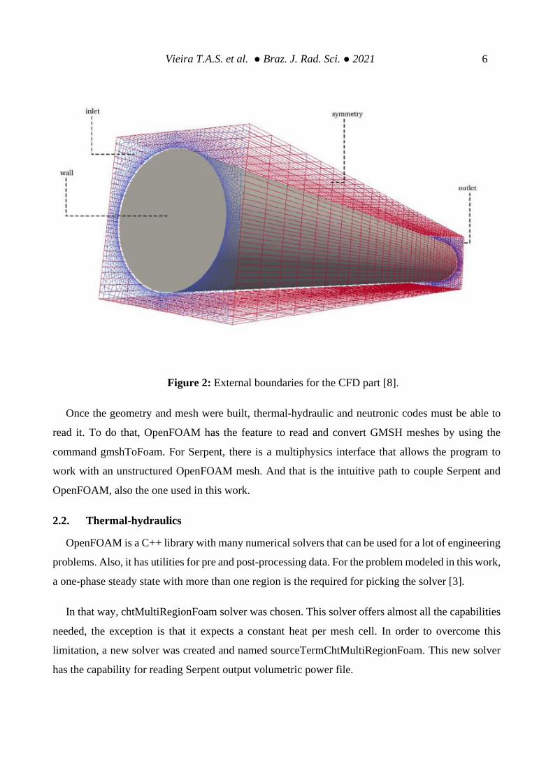
different materials. This initial 2D mesh was extruded then, by 35 layers. This extrusion is shown in
Fig.2. The total number of mesh elements is 346,675.
Figure 1: Horizontal mesh discretization slice exploded showing the three regions used by
thermal–hydraulic and neutronic [8].
Vieira T.A.S. et al. ● Braz. J. Rad. Sci. ● 2021 6
Figure 2: External boundaries for the CFD part [8].
Once the geometry and mesh were built, thermal-hydraulic and neutronic codes must be able to
read it. To do that, OpenFOAM has the feature to read and convert GMSH meshes by using the
command gmshToFoam. For Serpent, there is a multiphysics interface that allows the program to
work with an unstructured OpenFOAM mesh. And that is the intuitive path to couple Serpent and
OpenFOAM, also the one used in this work.
2.2. Thermal-hydraulics
OpenFOAM is a C++ library with many numerical solvers that can be used for a lot of engineering
problems. Also, it has utilities for pre and post-processing data. For the problem modeled in this work,
a one-phase steady state with more than one region is the required for picking the solver [3].
In that way, chtMultiRegionFoam solver was chosen. This solver offers almost all the capabilities
needed, the exception is that it expects a constant heat per mesh cell. In order to overcome this
limitation, a new solver was created and named sourceTermChtMultiRegionFoam. This new solver
has the capability for reading Serpent output volumetric power file.

Vieira T.A.S. et al. ● Braz. J. Rad. Sci. ● 2021 7
Other challenge, a smaller one, was that the used version of OpenFOAM (version 6) for
chtMultiRegionFoam does not give to the user the possibility to apply the SIMPLE pressure-velocity
corrector (most used for steady state simulations). The actual version only provides the PISO and
PIMPLE (mixed SIMPLE and PISO algorithms) corrector, but it’s possible to adapt PIMPLE to work
fine (just like SIMPLE) for steady state calculations.
About the solver developed itself, it has the same basic premises that the initial solver
(chtMultiRegionFoam). That means, the fluid dynamic is governed by the conservation equations
(momentum, continuity and energy). Initially, the solver separates fluid regions from solid regions.
Then solves the appropriated equations for each type of region, beginning with solid in this case.
Also, for solving the problem, the solver takes into account the thermal-physical properties of each
material obviously. These properties are defined separately for each region.
The thermal-physical properties used were almost polynomial (taking the variation with
temperature) and are presented in Table 2. In coolant material, the properties on Table 2 are valid for
273 to 373 K. For fuel and cladding, the properties are valid for 293 to 893 K. These variations and
polynomials were taken from reference [9]. The density for solids presented low variation with
temperature and therefore constant values were used. More than one volumetric power were used,
and for the highest value (7930 W) the fluid viscosity was considered constant. That assumption has
to be made because of the validity for the chosen polynomial. In some minor cells of this specific
case the water reached more than 373 K and at these conditions the polynomial viscosity is not
reliable. For turbulence modeling, k-ε was chosen because of it’s wide range of usage.
Regarding the external boundaries for the CFD simulation, Fig. 2 presents the definitions used.
Going beyond, Table 3 shows the initial conditions for thermal-hydraulics calculations. The
discretization schemes and solver settings for each field are shown in Tables 4 and 5, respectively.

Vieira T.A.S. et al. ● Braz. J. Rad. Sci. ● 2021 8
Table 2: thermal–physical properties used
Material Density Specific heat Thermal-
conductivity Viscosity
Fuel 6280
0.294
+6.196e−4 T –
2.748e−9 T2
+1.354e−11 T3
22.872
–4.3131e−2 T
1.1240e−4 T2 –
1.0039e−7 T3
-
Cladding 2705
0.892
+4.4361e−4 T
+3.6326e−8 T2
223.7
–4.7560e−2 T
+1.0215e−5 T2 –
1.8887e−8 T3
-
Coolant
765.33 +
1.8142T –
0.0035T2
28.07e3
–0.2817e3T +
1.25T2.
–2.48e−3T3 +
1.857e−6 T4
–0.5752 +
6.397e−3 T –
8.151e−6 T2
9.67e−2
–8.207e−4T +
2.344e−6 T2 –
2.244e−9 T3
a. All physical quantities in S.I.

Vieira T.A.S. et al. ● Braz. J. Rad. Sci. ● 2021 9
Table 3: Main boundary conditions used for thermal-hydraulic.
Region Field Boundary Type Value
Coolant T inlet fixed value 300 K
Coolant T outlet zero gradient -
Coolant U inlet fixed value 0.1 [m/s]
Coolant U outlet zero gradient -
Coolant K - - -
Coolant K - - -
Coolant Eps inlet; outlet - -
Coolant p_rgh inlet zero gradient -
Coolant p_rgh outlet fixed value 0 [kg/m.s2 = Pa]
Cladding T wall zero gradient -
Cladding Q internal field uniform 0 [W/m3]
Fuel T wall zero gradient -
Fuel Q internal field nonuniform volPower [W/m3]

Vieira T.A.S. et al. ● Braz. J. Rad. Sci. ● 2021 10
Table 4: Discretization schemes.
Region/Eq.
Term
Type of scheme
gradient divergence laplacian interpolation normal to cell
face
Coolant Least Squares Bounded
Gauss upwind
Gauss linear
limited 1.0 Linear Limited 1.0
Cladding Gauss linear - Gauss linear
uncorrected Linear Uncorrected
Fuel Gauss linear - Gauss linear
uncorrected Linear Uncorrected

Vieira T.A.S. et al. ● Braz. J. Rad. Sci. ● 2021 11
Table 5: Solver settings for each field.
Field Type of solver Convergence criteria Value
H Preconditioned bi-
conjugate gradient
10−5 1.0
ρ Preconditioned bi-
conjugate gradient 10−5 0.7
p.
Generalized
geometric-algebraic
multi-grid
10−5 0.7
P final
Generalized
geometric-algebraic
multi-grid
10−5 0.7
U
Preconditioned bi-
conjugate gradient for
asymmetric matrices
10−5 0.7
2.3. Neutronics
The chosen neutronic code Serpent (was used Serpent 2.1.30) is currently under development at
VTT Technical Research Centre of Finland [2]. Is a state-of-the-art Monte Carlo reactor physics, but
can be used for another applications. Nowadays, it has multiphysics interface that allows coupling
with external CFD codes, specially for OpenFOAM. Serpent has the feature to reads OpenFOAM
meshes with minor adjustments. Specifically, some files must be created (materials and map). Going
forward, Serpent writes a file for OpenFOAM format with a volumetric power per mesh cell. This
whole process illustrates that those codes are easily coupled.
More about Serpent, it’s a code with special methods for efficiency in neutron simulation. For this
purpose, Woodcock delta tracking method was implemented. This method works by the concept of

Vieira T.A.S. et al. ● Braz. J. Rad. Sci. ● 2021 12
virtual collisions, where no material differentiation is required during a cycle. The result of this
method application is that it simplifies the geometry routine and reduces calculation time.
The results of Serpent calculations comes in output files. These files must be determined by user,
but at least one is created with the general data of the simulation. In this work, beyond the standard
file, the volumetric power distribution file (volPower) was made as well. The different power values
used in Serpent (1980, 3970 and 7930 W) comes from full core power values, that are respectively
50, 100 and 200 kW.
The materials data for a reference temperature (600 K) and its proportion were presented in Table
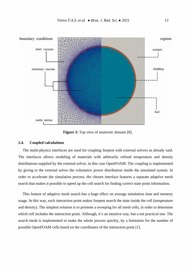
6. Also, the neutronic model with boundary conditions is generally showed in Fig. 3. The nuclear
data library used for the cross section of the materials was ENDF/B-VII.1.
Table 6: Material composition for cross-sections generation with Serpent 2.1.30
Material Material code Atomic fraction
Fuel
H (in zyrconium
hydrade); Zr; U235;
U238
1001.06c;
4000.06c;
92235.06c;
92238.06c
3.7525e−2 ;
3.7727e−2 ;
2.5744e−4 ;
1.0167e−3
Cladding Al 13027.06c
6.0261e−2
Coolant H; O 1001.06c;
8016.06c
6.6653e−2 ;
3.3327e−2
Vieira T.A.S. et al. ● Braz. J. Rad. Sci. ● 2021 13
Figure 3: Top view of neutronic domain [8].
2.4. Coupled calculations
The multi-physics interfaces are used for coupling Serpent with external solvers as already said.
The interfaces allows modeling of materials with arbitrarily refined temperature and density
distributions supplied by the external solver, in this case OpenFOAM. The coupling is implemented
by giving to the external solver the volumetric power distribution inside the simulated system. In
order to accelerate the simulation process, the chosen interface features a separate adaptive mesh
search that makes it possible to speed up the cell search for finding correct state point information.
This feature of adaptive mesh search has a huge effect on average simulation time and memory
usage. In this way, each interaction point makes Serpent search the state inside the cell (temperature
and density). The simplest solution is to promote a sweeping for all mesh cells, in order to determine
which cell includes the interaction point. Although, it’s an intuitive way, but a not practical one. The
search mesh is implemented to make the whole process quickly, by a limitation for the number of
possible OpenFOAM cells based on the coordinates of the interaction point [1].

Vieira T.A.S. et al. ● Braz. J. Rad. Sci. ● 2021 14
The search mesh is in a certain way, a cartesian mesh overlapping the OpenFOAM mesh. Yet, as
the search mesh is cartesian, the capability corresponds to the interaction point that can be determined
from the interaction coordinates with simple arithmetic operations (speedy computational process).
To define the right mesh cell, only those cells whose bounding boxes fall into the search mesh cell
were checked.
The unstructured mesh based interface (chosen one) has the feature for passing of density and
temperature fields without modification from OpemFOAM into Serpent. In exchange, Serpent is able
to pass a power distribution back to the CFD code.
For this work, only the first process was made, that is, Serpent was started and at the end of this
calculation, the output was used to run OpenFOAM. The way back is still under development, along
with the fully coupled calculation methodology. In order to generates Serpent files (map, materials),
Python scripts were used.
3. RESULTS AND DISCUSSION
The methods used in this work generated as result the Fig. 4 and Fig. 5. The Fig. 4 shows the
power profiles (1980, 3970 and 7980 W) resulting of Serpent simulation. That profiles are physically
consistent, that means, there are more fissile material in the middle of the used geometry, also the
boundary conditions for the top and bottom parts were configured as vacuum.
In that way, the Fig. 4 (a) shows good agreement (qualitatively) with (b) for all power profiles.
Moreover, in Fig. 4 (a) it can be seen that Monte Carlo simulations with discretized domain generates
a less smooth power profile than the deterministic simulations. That is expected to happen because is
difficult to obtain good statistical results (relative error) in such small portions of the geometry (cells),
even with small relative error (less than 15 pcm). The results obtained from steady state neutronic
calculations are shown in Table 7.

Vieira T.A.S. et al. ● Braz. J. Rad. Sci. ● 2021 15
Figure 4: Volumetric power distribution (a) Serpent / OpenFOAM; (b) Milonga / OpenFOAM.

Vieira T.A.S. et al. ● Braz. J. Rad. Sci. ● 2021 16
Figure 5: Power and temperature profile (a) Axial position; (b)Radial position.
Despite of the qualitative comparison, the truly important results of this work are shown in Fig. 5.
In this figure, is possible to see the axial and radial temperature and power profiles. Both results
shows good agreement with those showed in literature [8].

Vieira T.A.S. et al. ● Braz. J. Rad. Sci. ● 2021 17
However, the radial power profiles showed a flaw in the use of Serpent with unstructured mesh.
The curves presented steps looking like noise signal. That can be explained from the difficulty in
have enough particles in every domain cell from Monte Carlo simulation.
Table 7: Results of stand-alone neutronic calculations.
Fuel pin power [kW] Full core power equivalence
[kW] Standalone keff
1.980 50 1.08844 + − 10pcm
3.970 100 1.08877 + − 10pcm
7.930 200 1.08861 + − 7.5pcm
The behavior for temperature profiles (radial and axial) are intuitive, that is, where there is more
fissile material, there is higher temperature values given from the mesh cells.
The axial power profile is the one that almost every work involving reactors neutronic behavior
uses. In this way, the result of this paper is adequate, since shows the peak at center of pin and the
breaks at materials interfaces.
At last, the results shows physical consistency in a way that with more given energy for the system,
higher were the temperatures and power profiles.
4. CONCLUSION
In this paper, stand alone coupled simulations were performed for a IPR-R1 TRIGA reactor fuel
rod. The simulation was started with neutronics, followed by thermal-hydraulics where the whole
process ended. Three given power values were used, according to the reactor power capacity. The

Vieira T.A.S. et al. ● Braz. J. Rad. Sci. ● 2021 18
simulations where made by using Serpent as neutronic code and a modified OpenFOAM solver for
thermal-hydraulics.
The results showed good agreement with the literature for the same reactor and with resembling
methods. Those produced results were encouraging in qualitative analysis. For more complete
conclusions, further simulations must be provide, varying several conditions, such cross-section
libraries, geometries and total given power.
Moreover, a fully coupled scheme with several iterations between the neutronic and thermal-
hydraulic codes must be provided. In this way, the initial methodology presented in this paper is vital
as part of the goal.
ACKNOWLEDGMENT
This research project is supported by the following Brazilian institutions: Universidade Fed-
eral de Minas Gerais (UFMG), Nuclear Technology Development Center (CDTN), Brazilian Nuclear
Energy Commission (CNEN), Research Support Foundation of the State of Minas Gerais (FAPE-
MIG) project PPP APQ-01242-14 and Brazilian Council for Scientific and Technological Develop-
ment (CNPq) project Universal 427868/2016-5 and Coordenação de Aperfeiçoamento de Pessoal de
Nível Superior (CAPES).
REFERENCES
1. “Coupling Serpent and OpenFOAM for neutronics CFD multi-physics calculations”,
https://aaltodoc.aalto.fi/bitstream/handle/123456789/17759/ master_Tuomi-
nen_Riku_2015.pdf?sequence=1&isAllowed=y
(2019).

Vieira T.A.S. et al. ● Braz. J. Rad. Sci. ● 2021 19
2. LEPPANEN, J. et al “The Serpent Monte Carlo code: Status, development and applications
in 2013.”, Annals of Nuclear Energy, 82, pp. 142–150, (2015).
3. “OpenFOAM: User Guide version 6”, http://foam.sourceforge.net/docs/Guides-a4/Open-
FOAMUserGuide-A4.pdf
(2018).
4. IVANOV, K.; AVRAMOVA, M.“ Challenges in coupled thermal–hydraulics and neutronics
simulations for LWR safety analysis”, Annals of Nuclear Energy, 34, pp. 501–513, (2007).
5. FERRARO, D. et al, “A multi-physics analysis for the actuation of the SSS in Opal reactor”,
Nuclear Sciences & Technologies, 4, pp. 8, (2018).
6. TUOMINEN, R.; VALTAVIRTA, V.; and LEPPANEN, J.“ Application of the Serpent-
OpenFOAM coupled code system to the SEALER reactor core”, Physor, Mexico, april,
(2018).
7. MARTIN, W.“ Challenges and prospects for whole-core Monte Carlo analysis”, Nuclear En-
gineering and Technology, 44, (2012).
8. VASCONCELOS, V. et al “Coupled unstructured fine-mesh neutronics and thermal–hydrau-
lics methodology using open software: A proof-of-concept”, Annals of Nuclear Energy, 115,
pp. 173–185, (2018).
9. “Acoplamento neutrônico e termo-hidráulico usando os códigos milonga e Open- FOAM:
uma abordagem com software livre”,
http://www.repositorio.cdtn.br:8080/jspui/bitstream/123456789/1220/1/
Tese%20Vitor%20Vasconcelos.pdf
(2016).

Vieira T.A.S. et al. ● Braz. J. Rad. Sci. ● 2021 20
10. GEUZAINE, C. and REMACLE, J. F. “Gmsh: a three-dimensional finite element
mesh generator withbuilt-in pre-and post-processing facilities”, International Journal for
Numerical Methods in Engineering, 0, pp. 1–24, (2009).