ongc specs
TRANSCRIPT
FORMAT No. Ref. PROCEDURE No. ISSUE No. REV. No. REV. DATE:
ODS/SOF/004B ODS/SOP/008 TO 015 01 01 15/10/2003
OFFSHORE
DESIGN
SECTION
MUMBAI
REGION
GENERAL
SPECIFICATION
FOR
MATERIALS,
FABRICATION AND
INSTALLATION OF STRUCTURE
SPEC. No. 6001F
Rev. No. 3
Discipline: Structural
PAGE :Page 1 of 58
GENERAL SPECIFICATION
FOR
MATERIAL, FABRICATION AND
INSTALLATION OF STRUCTURE
OIL AND NATURAL GAS CORPORATION LTD.
INDIA
MVV VNM VKK ISSUED FOR
BID 58 30.06.05 3
PREP
BY RED BY
APPD
BY REMARK
TOTAL NOS.
OF PAGES DATE
REV.
No.
FORMAT No. Ref. PROCEDURE No. ISSUE No. REV. No. REV. DATE:
ODS/SOF/004B ODS/SOP/008 TO 015 01 01 15/10/2003
OFFSHORE
DESIGN
SECTION
MUMBAI
REGION
GENERAL
SPECIFICATION
FOR
MATERIALS,
FABRICATION AND
INSTALLATION OF STRUCTURE
SPEC. No. 6001F
Rev. No. 3
Discipline: Structural
PAGE :Page 2 of 58
CONTENTS
1.0 MATERIAL
2.0 FABRICATION
3.0 INSTALLATION
FORMAT No. Ref. PROCEDURE No. ISSUE No. REV. No. REV. DATE:
ODS/SOF/004B ODS/SOP/008 TO 015 01 01 15/10/2003
OFFSHORE
DESIGN
SECTION
MUMBAI
REGION
GENERAL
SPECIFICATION
FOR
MATERIALS,
FABRICATION AND
INSTALLATION OF STRUCTURE
SPEC. No. 6001F
Rev. No. 3
Discipline: Structural
PAGE :Page 3 of 58
1.0 MATERIAL
1.0.1 Scope & General
This specification defines the minimum requirements for the manufacture and
supply of structural materials for uses in the fabrication of the Platform.
If a deviation from these specifications or a substitution of material is sought,
the Contractor shall submit written request to Company along with necessary
supporting documents including test results, manufacturer's certificate etc.,
allowing reasonable time for evaluation without disruption of the construction
schedule. It shall be the Contractor's responsibility to satisfy the Company that
the proposed deviation or substitution will in no way be detrimental to the
quality of the works intended in the bid package. The Company may ask for
additional information & testing/retesting which the Company may consider
necessary, which the Contractor shall carry out at no extra time and cost to the
Company.
1.0.2 CODES AND STANDARDS
1.0.2.1 Mandatory Indian Statutory requirement.
This document has been prepared to the International standards detailed
hereunder. The Contractor shall ensure that the work is executed in accordance
with all mandatory Indian Statutory and regulatory requirements.
1.0.2.2 Codes and Standards & Regulations
The requirements of the latest published versions of the following listed Codes,
Recommended Practices, Specifications and standards shall be complied by the
Contractor.
1.0.2.3 American Society of Mechanical Engineers (ASME)
ASME B1.1 United Screw Threads (UN & UNR Thread Form)
ASME B18.2.2 Square and Hex Nuts
ASME B18.21.1 Lock Washers
1.0.2.4 American Petroleum Institute (API)
API RP 2A Recommended Practice for Planning, Designing and
Constructing Fixed Offshore Platforms – Working
Stress Design
FORMAT No. Ref. PROCEDURE No. ISSUE No. REV. No. REV. DATE:
ODS/SOF/004B ODS/SOP/008 TO 015 01 01 15/10/2003
OFFSHORE
DESIGN
SECTION
MUMBAI
REGION
GENERAL
SPECIFICATION
FOR
MATERIALS,
FABRICATION AND
INSTALLATION OF STRUCTURE
SPEC. No. 6001F
Rev. No. 3
Discipline: Structural
PAGE :Page 4 of 58
API Spec 2B API Specification for Fabricated Structural Steel Pipe.
API SPEC 2L Recommended Practice for Design of Heliport for
Offshore Structure-Planning, Designing and
Constructing Heliport for Fixed Offshore Platforms.
API Spec 2H API Specification for Carbon Manganese Steel Plate
for Offshore Platform Tubular Joints.
2MT1 As Rolled carbon manganese Steel Plate with
improved toughness for Offshore Structure.
API RP 2X Recommended Practice for Ultrasonic examination
and guidelines of offshore Structural fabrication and
guidelines for qualification of Ultrasonic Technicians.
API Spec 5L API Specification for Line Pipe.
API Spec 10A Oil Well Cement Class -G
1.0.2.5 American Society for Testing and Materials (ASTM)
ASTM A 6 General Requirements for Rolled Structural Steel Bars,
Plates, Shapes and Sheet Pilling.
ASTM A36 Structural Steel
ASTM A 53 Pipe, Steel, Black and Hot-Dipped, Zinc-Coated Welded
and Seamless.
ASTM A106 Seamless Carbon Steel Pipe for High Temperature Service
ASTM A109 Compressive Strength of Cement Grout.
ASTM A123 Zinc (Hot-Dip Galvanized) Coatings on Iron and Steel
Products
ASTM A153 Zinc-Coating (Hot-Dip) on Iron and Steel Hardware
ASTM A 182 Stainless steel Pipes
ASTM A 193 Alloy Steel and Stainless Steel Bolting Materials for High
Temperature Service.
FORMAT No. Ref. PROCEDURE No. ISSUE No. REV. No. REV. DATE:
ODS/SOF/004B ODS/SOP/008 TO 015 01 01 15/10/2003
OFFSHORE
DESIGN
SECTION
MUMBAI
REGION
GENERAL
SPECIFICATION
FOR
MATERIALS,
FABRICATION AND
INSTALLATION OF STRUCTURE
SPEC. No. 6001F
Rev. No. 3
Discipline: Structural
PAGE :Page 5 of 58
ASTM A 194 Carbon and Alloy Steel Nuts for Bolts for High Pressure
and High Temperature Service.
ASTM A 240 Stainless Steel plates
ASTM A307 Carbon Steel Bolts and Studs.
ASTM A325 High Strength Bolts for Structural Steel Joints.
ASTM A 370 Mechanical Testing of Steel Products.
ASTM A490 High Strength Steel Bolts for Structural Steel Joints.
ASTM A500 Cold Formed Welded and Seamless Carbon Steel Structural
Tubing in Rounds and Shapes.
ASTM A563 Carbon and Alloy Steel Nuts.
ASTM A 572 High - Strength Low-Alloy Columbium –Vanadium Steel
of Structural Steel.
ASTM A 578 Specification for Straight Beam Ultrasonic Examination of
plain and Clad Steel Plates for Special Applications.
ASTM A 633 Specification for Normalized High Strength Low Alloy
Structural Steel Plate.
ASTM B 695 Coatings of Zinc Mechanically Deposited on Iron and
Steel.
ASTM C150 Portland Cement.
ASTM D 2000 Classification System for Rubber Products in Automotive
Applications.
ASTM F 436 Hardness Steel Washers for Use with High Strength Bolts.
1.0.2.6 American Welding Society (AWS)
AWS D1.1 Structural Welding Code – Steel.
1.0.2.7 American Institute of Steel Construction (AISC)
AISC Manual of Steel Construction.
FORMAT No. Ref. PROCEDURE No. ISSUE No. REV. No. REV. DATE:
ODS/SOF/004B ODS/SOP/008 TO 015 01 01 15/10/2003
OFFSHORE
DESIGN
SECTION
MUMBAI
REGION
GENERAL
SPECIFICATION
FOR
MATERIALS,
FABRICATION AND
INSTALLATION OF STRUCTURE
SPEC. No. 6001F
Rev. No. 3
Discipline: Structural
PAGE :Page 6 of 58
1.0.2.8 Indian Standards Institute (ISI)
IS 2062 Steel Code for General structural purpose
IS 883 Code of Practice of Structural Timber for Buildings
IS 269 Ordinary Portland Cement
IS 3502 Steel Chequered Plate.
IS 1786 FE 415 – High Strength Deformed Bars
1.0.2.9 EN-10025 European Standard (EN-10025)
1.0.2.10 Spec. 6002 F Specification for Design, Material, fabrication and
Installation of Composite material for Secondary
Structures.
1.1. STRUCTURAL STEEL
1.1.1 Delivery
Steel shall be delivered in accordance with the requirements of ASTM A6 and
as specified in this document.
1.1.2 Condition of Material
Structural steel to be used shall be new, unused (not reconditioned) and free of
defects. Steel plates and rolled shapes shall be free of rolling defects, burrs,
rough spots and other surface imperfections. Surface finish for steel surfaces
shall be such that only blasting and no grinding is required to achieve a surface
acceptable for painting. Plate edges shall be even, smooth, and free of
laminations. Edge shearing of plates of a thickness of 25 mm or larger shall not
be permitted.
Except where requested by specific supplements, systematic Ultrasonic Testing
(UT) of steel plates at fabrication time is not required. However, any delivered
plate which fails to meet the maximum discontinuity requirements of AWS
D1.1 Section 3.2.3 e.g. 4% rule with adjustments shall be replaced. These rules,
written for edge discontinuities, shall apply to the body of the plate, since plates
are generally used as rolled tubulars and must provide footprints (i.e. edges) to
other tubular where small region outside footprints and edges in accordance
with AWS D1.1.
FORMAT No. Ref. PROCEDURE No. ISSUE No. REV. No. REV. DATE:
ODS/SOF/004B ODS/SOP/008 TO 015 01 01 15/10/2003
OFFSHORE
DESIGN
SECTION
MUMBAI
REGION
GENERAL
SPECIFICATION
FOR
MATERIALS,
FABRICATION AND
INSTALLATION OF STRUCTURE
SPEC. No. 6001F
Rev. No. 3
Discipline: Structural
PAGE :Page 7 of 58
1.1.3 Dimensional Tolerances
Dimensional tolerances of individual tubular sections 457 mm diameter and
above shall be in accordance with API 2B. A maximum of 1.5% cold
expansion shall be allowed. The use of electric resistance welded (ERW) or
spiral welded pipe is prohibited. Only SAW or DSAW tubulars welded with a
qualified procedure in accordance with AWS D1.1 or seamless pipe is
acceptable for structural use. Hydrostatic testing of structural tubular is not
required. Rolled tubulars shall not have more than one longitudinal seam.
1.1.4 Material Storage
All material, whether procured or fabricated, shall be stored above ground on
pallets, timber cribbing or similar supports. The material shall be stored above
the level of standing water and be kept free from dirt, grease, paint spray and
other foreign matters.
1.1.5 Material Marking
All material shall be identified by coded marking and/or heat numbers and will
be in accordance with ASTM A6 where applicable. All identification markings
shall be clearly visible and capable of remaining intact through the completion
of fabrication. The material identification and traceability procedure shall be
developed by the Contractor to identify each structural member with Heat
Number /Cast Number to correlate the test certificates. This procedure shall be
applicable from its receipt and storage through sub-assembly and final erection.
Unidentified material shall not be acceptable in accordance with API RP 2A.
1.1.6 Inspection and Testing
1.1.6.1 Mill Tests and Mill Certificates
All mandatory inspection and testing listed under the basic specification to
which the steel is manufactured and all supplementary and/or additional
requirements specified in this specifications for the concerned grade shall be
documented to have been satisfied through mill tests and mill test certificates. In
addition product analysis shall be conducted on one sample per heat.
One set of all relevant certificates and reports, clearly legible and in the English
language shall he submitted by Contractor to Company. SI Units shall be used
in all documentation. The mill certificates shall be signed by Manufacturer's
Quality Assurance Representative and where specified by Company, an
independent Third Party acceptable to Company to state compliance with this
specification.
FORMAT No. Ref. PROCEDURE No. ISSUE No. REV. No. REV. DATE:
ODS/SOF/004B ODS/SOP/008 TO 015 01 01 15/10/2003
OFFSHORE
DESIGN
SECTION
MUMBAI
REGION
GENERAL
SPECIFICATION
FOR
MATERIALS,
FABRICATION AND
INSTALLATION OF STRUCTURE
SPEC. No. 6001F
Rev. No. 3
Discipline: Structural
PAGE :Page 8 of 58
1.1.6.2 Contents
The mill certificates and reports shall include all relevant information including,
but not restricted to the following:
a) Identification
Mill Location, Purchase Order and item Number, Date of manufacture,
Method of Manufacture, steel making process, Mill Heat / Cast
Numbers, bar or bloom number, plate number, supply condition,
dimensions, specification and grade of steel (basic specification).
b) Composition
Ladle (Heat) analysis and product analysis and Carbon Equivalent. All
elements used in the carbon equivalent formula shall be analyzed and
reported. Elements which are not specified for any grade in the
respective codes shall not be intentionally added without specific
approval from Company prior to manufacture.
c) Mechanical Properties
- Tensile strength, Yield Stress, Ultimate strength and Percent
elongation.
- Charpy V-notch tests results, (if required).
- Through thickness properties, (if required).
- Strain age test results, (if required).
d) Non-destructive test results, (if required).
e) Details of heat treatment, if performed.
f) Impact testing specimen size, orientation, impact values and test
temperature.
g) Reports signifying meeting other specific/ supplementary requirements
for the specification for the material.
h) Supplementary information relating to manufacturing process.
1.1.6.3 Material Certification
On request by Company original Mill Test Certificate shall be made available to
the Company for verification. Material with Mill Test Certificates, that do not
satisfy the specified requirements herein shall be rejected and removed from the
storage area.
FORMAT No. Ref. PROCEDURE No. ISSUE No. REV. No. REV. DATE:
ODS/SOF/004B ODS/SOP/008 TO 015 01 01 15/10/2003
OFFSHORE
DESIGN
SECTION
MUMBAI
REGION
GENERAL
SPECIFICATION
FOR
MATERIALS,
FABRICATION AND
INSTALLATION OF STRUCTURE
SPEC. No. 6001F
Rev. No. 3
Discipline: Structural
PAGE :Page 9 of 58
1.1.6.4 Material Testing
This section gives the minimum requirements of the materials supplied to this
specification. Unless stated otherwise, all testing shall be performed in
accordance with ASTM A6 "Standard Specification for General Requirements
for Rolled Steel Plates, shapes, sheet piling and Bars for structural use" and
ASTM A 370 “Mechanical Testing of steel products”.
1.1.7 Ex-Stock Steel
Steel manufactured two years prior to the actual use shall not be accepted.
However, in case of any immediate requirement of any small quantity, supply of
ex-stock steel in good condition and free from rust and pitting may be offered
for Company’s consideration. Such material shall be easily identifiable with
respect to its Heat / Cast number, Manufacturer’s stamp, colour coding, Grade
etc., as given in the mill test certificate. The mill test certificates of such
material shall meet the required specification. The Contractor shall satisfy
Company by means of additional tests as directed on the company’s inspection
at no extra time and cost to the company.
1.1.8 Steel Manufacturing Process
Only product manufactured by the electric arc furnace or the basic oxygen
processes is acceptable as structural steel. Bessemer process, rimmed or capped
steels are not acceptable. Material for through thickness application shall be
vacuum degassed or VAD or ladle refining process while molten. Rejected
steels and unidentified steel are not acceptable. Specifically, rejected high
strength steel (350 MPs) is not to be substituted for low strength steel (250
MPa).
1.1.9 Class and Types of Structural Steel
Steel material types defines by shape and grade or strength designation
consisting of the specified minimum yield strength in MPa. In the case where
through thickness properties are required for attachments and loads
perpendicular to the plate surface, a suffix “Z” has been added. Chemical
composition of steel shall be in accordance with the respective standards with
supplementary requirements given in Sections 1.1.9.4 and supply conditions
given in Section 1.1.9.5 hereunder.
1.1.9.1 Class of Material
Class A
FORMAT No. Ref. PROCEDURE No. ISSUE No. REV. No. REV. DATE:
ODS/SOF/004B ODS/SOP/008 TO 015 01 01 15/10/2003
OFFSHORE
DESIGN
SECTION
MUMBAI
REGION
SPEC. No. 6001F
Rev. No. 3
Discipline: Structural
PAGE :Page 10 of 58
Class A material are suitable for critical applications involving stress
concentrations, high restraint, the possibility of plastic strain and lack of
redundancy. Charpy impact test in accordance with the specified Standard is
mandatory. Carbon equivalent shall be as per respective standard and
specification.
Class B
Class B material are intended for less critical applications but still involve the
possibility of plastic strain and therefore the need for impact testing. The
material shall meet the Charpy requirements of the specified Standard and in
addition. Carbon equivalent shall be as per respective standard and
specification.
Class B material shall not exceed 63 mm. in thickness.
Class C
Class C materials are those, which have a history of successful applications in
welded structures at service temperatures above 0º C, for which impact testing is
not required. Applications are for primary and secondary members involving
moderate forming, low restraint and modest stress concentrations. Structural
redundancy should be provided by the design.
1.1.9.2 Types of Structural Steel
The following is a guideline for the selection of steels for use in offshore
structures. Contractor shall use steel type to suit fabrication methods, welding
procedure etc., for each structural steel type as specified.
Grades of Steel are covered in this specification are: -
Grade 250: Carbon Steel of yield strength 240-250
MPa (35-36 ksi).
Grade 350: Intermediate Strength steel of yield
strength 340-360 Mpa (50-52 ksi).
FORMAT No. Ref. PROCEDURE No. ISSUE No. REV. No. REV. DATE:
ODS/SOF/004B ODS/SOP/008 TO 015 01 01 15/10/2003
OFFSHORE
DESIGN
SECTION
MUMBAI
REGION
GENERAL
SPECIFICATION
FOR
MATERIALS,
FABRICATION AND
INSTALLATION OF STRUCTURE
SPEC. No. 6001F
Rev. No. 3
Discipline: Structural
PAGE :Page 11 of 58
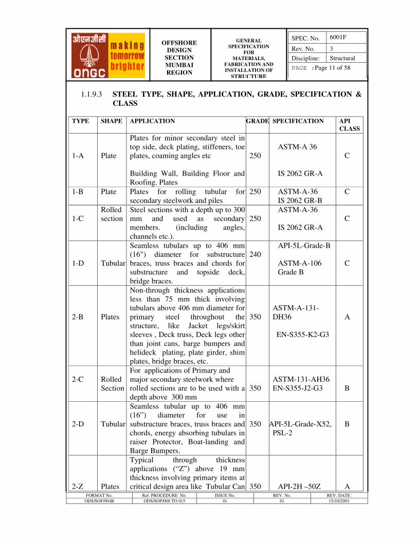
1.1.9.3 STEEL TYPE, SHAPE, APPLICATION, GRADE, SPECIFICATION &
CLASS
TYPE SHAPE APPLICATION GRADE SPECIFICATION API
CLASS
1-A
Plate
Plates for minor secondary steel in
top side, deck plating, stiffeners, toe
plates, coaming angles etc
Building Wall, Building Floor and
Roofing. Plates
250
ASTM-A 36
IS 2062 GR-A
C
1-B Plate Plates for rolling tubular for
secondary steelwork and piles
250 ASTM-A-36
IS 2062 GR-B
C
1-C
Rolled
section
Steel sections with a depth up to 300
mm and used as secondary
members. (including angles,
channels etc.).
250
ASTM-A-36
IS 2062 GR-A
C
1-D
Tubular
Seamless tubulars up to 406 mm
(16") diameter for substructure
braces, truss braces and chords for
substructure and topside deck,
bridge braces.
240
API-5L-Grade-B
ASTM-A-106
Grade B
C
2-B
Plates
Non-through thickness applications
less than 75 mm thick involving
tubulars above 406 mm diameter for
primary steel throughout the
structure, like Jacket legs/skirt
sleeves , Deck truss, Deck legs other
than joint cans, barge bumpers and
helideck plating, plate girder, shim
plates, bridge braces, etc.
350
ASTM-A-131-
DH36
EN-S355-K2-G3
A
2-C
Rolled
Section
For applications of Primary and
major secondary steelwork where
rolled sections are to be used with a
depth above 300 mm
350
ASTM-131-AH36
EN-S355-J2-G3
B
2-D
Tubular
Seamless tubular up to 406 mm
(16”) diameter for use in
substructure braces, truss braces and
chords, energy absorbing tubulars in
raiser Protector, Boat-landing and
Barge Bumpers.
350
API-5L-Grade-X52,
PSL-2
B
2-Z
Plates
Typical through thickness
applications (“Z”) above 19 mm
thickness involving primary items at
critical design area like Tubular Can
350
API-2H –50Z
A
FORMAT No. Ref. PROCEDURE No. ISSUE No. REV. No. REV. DATE:
ODS/SOF/004B ODS/SOP/008 TO 015 01 01 15/10/2003
OFFSHORE
DESIGN
SECTION
MUMBAI
REGION
GENERAL
SPECIFICATION
FOR
MATERIALS,
FABRICATION AND
INSTALLATION OF STRUCTURE
SPEC. No. 6001F
Rev. No. 3
Discipline: Structural
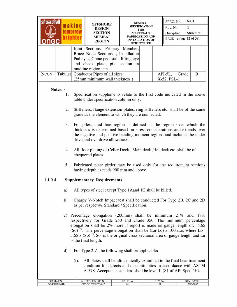
PAGE :Page 12 of 58
Joint Sections, Primary Member,
Brace Node Sections, , Installation
Pad eyes, Crane pedestal, lifting eye
and cheek plate, pile section in
mudline region, etc.
2-CON Tubular Conductor Pipes of all sizes
(25mm minimum wall thickness )
API-5L, Grade
X-52, PSL-1
B
Notes: -
1. Specification supplements relate to the first code indicated in the above
table under specification column only.
2. Stiffeners, flange extension plates, ring stiffeners etc. shall be of the same
grade as the element to which they are connected.
3. For piles, mud line region is defined as the region over which the
thickness is determined based on stress considerations and extends over
the negative and positive bending moment regions and includes the under
drive and overdrive allowances.
4. All floor plating of Cellar Deck , Main deck ,Helideck etc. shall be of
chequered plates.
5. Fabricated plate girder may be used only for the requirement sections
having depth exceeds 900 mm and above.
1.1.9.4 Supplementary Requirements
a) All types of steel except Type 1Aand 1C shall be killed.
b) Charpy V-Notch Impact test shall be conducted For Type 2B, 2C and 2D
as per respective Standard / Specification.
c) Percentage elongation (200mm) shall be minimum 21% and 18%
respectively for Grade 250 and Grade 350. The minimum percentage
elongation shall be 2% more if report is made on gauge length of. 5.65
(So) ½
. The percentage elongation shall be (Lu-Lo) x 100 /Lo, where Lo=
5.65 x (So) ½
, So is the original cross sectional area of gauge length and Lu
is the final length.
d) For Type 2-Z, the following shall be applicable:
(i). All plates shall be ultrasonically examined in the final heat treatment
condition for defects and discontinuities in accordance with ASTM
A-578. Acceptance standard shall be level II (S1 of API Spec 2H).
FORMAT No. Ref. PROCEDURE No. ISSUE No. REV. No. REV. DATE:
ODS/SOF/004B ODS/SOP/008 TO 015 01 01 15/10/2003
OFFSHORE
DESIGN
SECTION
MUMBAI
REGION
GENERAL
SPECIFICATION
FOR
MATERIALS,
FABRICATION AND
INSTALLATION OF STRUCTURE
SPEC. No. 6001F
Rev. No. 3
Discipline: Structural
PAGE :Page 13 of 58
(ii). Through Thickness (Z direction) tensile testing shall he performed as
per Supplementary requirement S4 of API Spec. 2H.
(iii) Individual plate testing as per S-3 of API-2H.
(iv) Charpy V-Notch toughness impact test at (-) 400C in Transverse
direction with minimum single value 34 Joules and average energy
value 41 Joules.
(v) The sulphur content of steel be as per clause 5.2 of Supplementary
requirement S-5 of Spec. API 2H.
(e) If micro alloying elements Nb, V, Ti are used, their total shall not exceed
0.2 percent.
(f) For Thermo-Mechanical Control Processing (TMCP) or equivalent steel
please refer Section 1.1.9.5 (ii) hereunder.
1.1.9.5 Supply Condition
(i) Steel Grades 2-B and 2-Z shall be supplied in Normalized Condition. Steel
Grades 1-C and 2-C (Rolled Section of flange thickness over 25 mm) shall be
supplied in Normalized condition. All other steel may be supplied in as rolled
condition.
(ii) If the manufacturer/supplier offers an alternative supply condition, e.g.
Thermo-Mechanical Control Processing (TMCP) or equivalent then the details
shall be submitted containing particulars of the manufacturer's past records
including details regarding production control, and weld-ability. The Weld-
ability test shall meet the requirements of API Spec. 2W including
Supplementary Requirements S 1, S 3, S 4, S 5, S 9 and S 11 of API Spec. 2W
and API RP 2Z.
1.1.10 Heat Treatment
Elements subject to press or roll forming where the temperature of the steel is
above 38 degree C and less than 427 degree C during forming operation shall be
stress relieved by heating the element to a temperature between 590°C and
620°C and cooling after a specified time.
1.1.11 Quality of finished Steel
The finished steel shall be presented for inspection such that the surface can be
readily inspected for defects. All surfaces shall be 100% visually inspected for
defects. Repair of plates by welding by Manufacturer or supplier is not
permitted.
FORMAT No. Ref. PROCEDURE No. ISSUE No. REV. No. REV. DATE:
ODS/SOF/004B ODS/SOP/008 TO 015 01 01 15/10/2003
OFFSHORE
DESIGN
SECTION
MUMBAI
REGION
GENERAL
SPECIFICATION
FOR
MATERIALS,
FABRICATION AND
INSTALLATION OF STRUCTURE
SPEC. No. 6001F
Rev. No. 3
Discipline: Structural
PAGE :Page 14 of 58
1.1.12 Material Substitution
Alternative Specifications or property grades for certain material may be
accepted with the prior approval of the Company, provided that it can be shown
to be equivalent or superior to the specifications as per code listed in the table in
Section 1.1.9.3 and the required properties and appropriate supplements of the
materials is complied with the material specified. When the proposed substitute
material have variation in chemical and Mechanical properties from the listed
codes, the contractor shall establish with reasoning the superiority/equivalent of
the alternate material.
1.2 CEMENT
1.2.1 Cement Grades
Unless otherwise stated on the bid drawings all cement provided for
construction, these platforms shall conform to one of the following.
Type A Portland Cement as per ASTM C-150 Type I or IS-269
Type B Oil well Cement as per API Specs-10A Class-G.-HSR Grade.
Cement supply to specifications equivalent to those listed above shall be
considered as substitution and shall require written approval of the Company to
this effect.
1.2.2 When a specific physical or chemical property of the grout or concrete is
warranted which is not achievable by controlling the proportions of the normal
constituents of the cement grout or concrete, additives to the cement grout or
cement concrete may be allowed. The Contractor shall submit to Company his
proposal for such additives giving details of the chemical composition of the
proposed additives and the specific properties of the cement grout or cement
concrete, Contractor proposed to achieve together with test results and other
relevant details. The Company shall within a reasonable period review and
convey to the Contractor its decision on such proposal. It shall be the
Contractor’s responsibility to satisfy the Company that his proposal will
satisfactorily meet the requirements of the works.
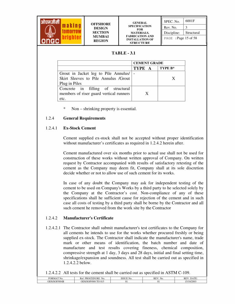
1.2.3 Usage Summary
Usage of different grades of cement shall be as given in Table 3.1.
FORMAT No. Ref. PROCEDURE No. ISSUE No. REV. No. REV. DATE:
ODS/SOF/004B ODS/SOP/008 TO 015 01 01 15/10/2003
OFFSHORE
DESIGN
SECTION
MUMBAI
REGION
GENERAL
SPECIFICATION
FOR
MATERIALS,
FABRICATION AND
INSTALLATION OF STRUCTURE
SPEC. No. 6001F
Rev. No. 3
Discipline: Structural
PAGE :Page 15 of 58
TABLE - 3.1
CEMENT GRADE
TYPE A TYPE B*
Grout in Jacket leg to Pile Annulus/
Skirt Sleeves to Pile Annulus /Grout
Plug in Piles
-
X
Concrete in filling of structural
members of riser guard vertical runners
etc.
X
* Non – shrinking property is essential.
1.2.4 General Requirements
1.2.4.1 Ex-Stock Cement
Cement supplied ex-stock shall not be accepted without proper identification
without manufacturer’s certificates as required in 1.2.4.2 herein after.
Cement manufactured over six months prior to actual use shall not be used for
construction of these works without written approval of Company. On written
request by Contractor accompanied with results of satisfactory retesting of the
cement as the Company may deem fit, Company shall at its sole discretion
decide whether or not to allow use of such cement for its works.
In case of any doubt the Company may ask for independent testing of the
cement to be used on Company's Works by a third party to he selected solely by
the Company at the Contractor’s cost. Non-compliance of any of these
specifications shall he sufficient cause for rejection of the cement and in such
case all costs of testing by a third party shall be borne by the Contractor and all
such cement he removed from the work site by the Contractor
1.2.4.2 Manufacturer's Certificate
1.2.4.2.1 The Contractor shall submit manufacturer's test certificates to the Company for
all cements he intends to use for the works whether procured freshly or being
supplied ex-stock. The Contractor shall indicate the manufacturer's name, trade
mark or other means of identification, the batch number and date of
manufacture and test results covering fineness, chemical composition,
compressive strength at 1 day, 3 days and 28 days, initial and final setting time,
shrinkage/expansion and soundness. All test shall be carried out as specified in
1.2.4.2.2 below.
1.2.4.2.2 All tests for the cement shall be carried out as specified in ASTM C-109.
FORMAT No. Ref. PROCEDURE No. ISSUE No. REV. No. REV. DATE:
ODS/SOF/004B ODS/SOP/008 TO 015 01 01 15/10/2003
OFFSHORE
DESIGN
SECTION
MUMBAI
REGION
GENERAL
SPECIFICATION
FOR
MATERIALS,
FABRICATION AND
INSTALLATION OF STRUCTURE
SPEC. No. 6001F
Rev. No. 3
Discipline: Structural
PAGE :Page 16 of 58
Shrinkage/expansion test shall be carried out as specified in ASTM designation
C-807-87. "Restrained Expansive Cement Mortar" or by similar acceptable
method.
1.2.4.2.3 Identification of the cement intended to be used for the works shall be co-
relatable with the identification on the manufacturer's test certificate.
1.2.4.3 Special Requirements
The following requirements shall apply unless specifically waived by the
Company or otherwise specified herein or on bid drawings.
1.2.4.3.1 For all cement used for the works where non-shrinking/expansive property is
desired shall have acceptance criteria as below:
Drying Shrinkage- 0.08 % at 28 days (as per ASTM C-596)
Expansion- 0.10%-0.30% at 28 days.
1.2.4.3.2 The total amount of chlorides calculated as free calcium chloride shall not
exceed 0.3 percent by weight of cement.
1.2.4.3.3 Compressive strength for Type-B cement shall not be less than 105 Kg/cm2
(1500 psi) in 24 hours and 422 Kg/cm2
(6000 psi) in 28 days. The grout shall
be of non-shrinking expansive type having density 1920 kg/m3. with
compressive strength shall not be less than 70 Kg/cm2 (1000 psi) in 24 hours
and 281 Kg/cm2 (4 000 psi) in 28 days at 27+2
0C
1.3 Miscellaneous Steel Items
1.3.1 Fasteners
Unless shown otherwise in the Drawings, all fasteners shall conform to the
following:
a) Lag screws and bolts shall be machined with American Standard Regular
Hexagonal Heads with American Standard Coarse Threads, Class-2.
b) Nuts shall be American Standard Regular Hexagonal.
c) Washers shall be standard round plate and/or machine lock unless shown
otherwise on the drawings.
d) All bolts for use in the submerged and splash zones shall be flouro-
polymer coated (XYLAN type ) or equivalent. Coating color for all bolts
and nuts shall be "Red". All nuts & bolts shall he of ASTM A-193 Grade
FORMAT No. Ref. PROCEDURE No. ISSUE No. REV. No. REV. DATE:
ODS/SOF/004B ODS/SOP/008 TO 015 01 01 15/10/2003
OFFSHORE
DESIGN
SECTION
MUMBAI
REGION
GENERAL
SPECIFICATION
FOR
MATERIALS,
FABRICATION AND
INSTALLATION OF STRUCTURE
SPEC. No. 6001F
Rev. No. 3
Discipline: Structural
PAGE :Page 17 of 58
B7 and nuts of ASTM A-194, grade 2H unless otherwise specified in
approved drawings.
1.3.2 Grating.
d) At Cellar Deck and above
Serrated flats for gratings shall conform to ASTM A-36 or IS 2062 Gr. A.
Cross bars shall be high strength deformed bars conforming to IS 1786 Gr.
Fe 415.
ii) Below Cellar Deck
Material shall be as per Spec. 6002 F.
1.3.3 Pipe Railing/Hand Rail
i) At Cellar Deck and above
Pipe railing/hand rail shall conform to Grade 1–D
ii) Below Cellar Deck
Material shall be as per Spec. 6002 F.
1.4 TIMBER
1.4.1 Usage
The specification for timber as per IS 883 shall govern the application of
timber used in:
a) Launch Truss runners of jackets.
b) Mud mats
Timber to be used for each of the above application shall meet the strength,
durability and dimensional requirements for the intended use. Contractor to
indicate the grades of timber along with their properties and satisfy Company
on their suitability for the proposed use.
1.4.2 Delivery & Storage
All timbers supplied for the works shall be delivered at the fabrication site in
sizes and lengths as required for the works and fully seasoned and treated with
preservatives.
FORMAT No. Ref. PROCEDURE No. ISSUE No. REV. No. REV. DATE:
ODS/SOF/004B ODS/SOP/008 TO 015 01 01 15/10/2003
OFFSHORE
DESIGN
SECTION
MUMBAI
REGION
GENERAL
SPECIFICATION
FOR
MATERIALS,
FABRICATION AND
INSTALLATION OF STRUCTURE
SPEC. No. 6001F
Rev. No. 3
Discipline: Structural
PAGE :Page 18 of 58
After delivery and prior to use all structural timbers shall be stored in such a
manner as to prevent decay and renewed development of defects. Preferably
timbers shall be piled into stacks upon well treated and even surfaced beams,
sleepers or brick pillars so as to be above ground level by at least 15 cm. The
stacks shall be protected from hot dry winds or direct sun and rain and shall be
accessible from all sides.
The stacks of timbers shall be appropriately marked so as to be readily
identifiable and correlatable with the purchase order, vendor’s certificate or
other inspection/test certificates.
1.4.3 Inspection & Testing
Inspection and testing of timber shall be carried out as per the grades of timber
supplied as per the IS 883 requirement.
1.5.0 RUBBER
1.5.1 SCOPE
Rubber products shall conform to the Requirements of ASTM D 2000.
This specification describes the minimum requirements for procurement,
manufacture, testing and supply of rubber products for use on offshore platforms
as required either as permanent component or as temporary installation and as
listed below:
1. Boat Landing - Shear Fenders
- Rub Strips
2. Barge Bumper - Shock Cell
- Rotating Bumper Rings
3. Jacket Leg - Rub strips
4. Jacket Leg/Skirt Sleeves - Diaphragm Closures
5. Jacket Leg/Skirt Sleeves - Grout Seal/Packer
6. Piles - Pile Closure
1.5.2 SITE CONDITIONS
Rubber compounds for the rubber products shall be able to withstand the extreme
marine environment indicated in the bid document.
FORMAT No. Ref. PROCEDURE No. ISSUE No. REV. No. REV. DATE:
ODS/SOF/004B ODS/SOP/008 TO 015 01 01 15/10/2003
OFFSHORE
DESIGN
SECTION
MUMBAI
REGION
GENERAL
SPECIFICATION
FOR
MATERIALS,
FABRICATION AND
INSTALLATION OF STRUCTURE
SPEC. No. 6001F
Rev. No. 3
Discipline: Structural
PAGE :Page 19 of 58
1.5.3 GENERAL REQUIREMENTS
Company requires that the offered products have had satisfactory past
performance in offshore environments. For each product, a base
specification/product trademark is furnished in the Technical requirement to
evaluate the level of performance required. In case the Contractor wishes to
propose an equivalent alternative product, approval for the same shall be obtained
by him in writing from the Company after furnishing complete technical details
and proven application record of the alternative offered, viz. technical properties,
manufacturing process, exposure to marine environments, successful offshore use
etc. The products so offered shall be supplied only from manufacturers with a
proven track record of supplying identical or similar products. Only products and
grades normally manufactured and listed in the manufacturer's catalogues shall be
supplied.
1.5.4 TECHNICAL REQUIREMENTS
This section details the various rubber products listed above alongwith their
minimum general requirements. Specific requirements alongwith base
specification/product trade mark for each product as given in Annexure-1. If
Contractor proposes an alternate system design for any component, the specific
requirements shall be suitably configured to meet the design criteria for that
components.
1.5.4.1 BOAT LANDING SYSTEM
The boat landing system is planned in such a way that it meets the requirements of
the Design Criteria. The boat landing is designed to be mounted on shear fenders
to absorb energy of impact. A set of low friction pads/strips are provided to act as
rubbing surface against the boat.
1.5.4.1.1 SHEAR FENDERS
The shear fender shall have solid rubber bonded between two parallel plates. The
plates shall be bolted to the boat landing at one end and supporting member at the
other end.
Testing shall be performed to 110 percent of design capacity and load deformation
- energy relationship reported.
1.5.4.1.2 BOAT LANDING RUBSTRIPS
The rub strips for boat landing shall be low friction type polyurethane minimum
150 mm width and 50 mm thickness bonded to back up plate/channel as shown in
the relevant drawings.
FORMAT No. Ref. PROCEDURE No. ISSUE No. REV. No. REV. DATE:
ODS/SOF/004B ODS/SOP/008 TO 015 01 01 15/10/2003
OFFSHORE
DESIGN
SECTION
MUMBAI
REGION
GENERAL
SPECIFICATION
FOR
MATERIALS,
FABRICATION AND
INSTALLATION OF STRUCTURE
SPEC. No. 6001F
Rev. No. 3
Discipline: Structural
PAGE :Page 20 of 58
1.5.4.2 BARGE BUMPER
The single boat landing plus barge bumper system mounted on a combination of
shock cells and shear fenders can be provided. Individual barge bumpers may also
be provided. The specification covers both the instances.
1.5.4.2.1 Shock Cells
The shock cells shall consist of two concentrically placed steel tubes with a
rubber annulus. The rubber material used in the shock cell shall be natural rubber
based. Manufacturing process of shock cells shall be such that the rubber is
slightly under a compressive strain rather than a tensile strain in the finished cell
assembly at zero loading. The process of pouring and moulding the rubber in the
annulus are not acceptable due to problem associated with shrinkage and
cracking.
The shock cells shall have a minimum overload capacity of 10% of the rated
energy. Each shock cell shall be individually tested for both axial and lateral
loading at least up to 110% of rated energy, and load-deformation-energy curves
shall be developed for each.
Following information shall be supplied by the shock cell vendor with his
quotation.
i. The load/deformation/energy relationship of the shock cell.
ii. The type and quality of rubber
iii. The manufacturing process of the shock cell
1.5.4.2.2 Rotating Bumper Rings
The function of the Rotating Rubber Rings is to transfer the lateral load to the
shock cell absorbing part of the energy of impact. The rubber ring shall have a
urethane facing. The rubber ring should be capable of rotating freely around the
vertical pipe.
Testing shall be performed to 110% of the rated energy. The load
deformation/energy characteristics of the Bumper Ring shall be obtained by
testing the ring with an outer steel sleeve to simulate the actual conditions.
1.5.4.3 PLATFORM RUBSTRIPS
Platform substructure protective rubstrips and rubstrips on boat landing shall be
an easily replaceable type so that if required, only damaged rubstrip need be
replaced. They shall be manufactured by the extrusion process. There shall be no
FORMAT No. Ref. PROCEDURE No. ISSUE No. REV. No. REV. DATE:
ODS/SOF/004B ODS/SOP/008 TO 015 01 01 15/10/2003
OFFSHORE
DESIGN
SECTION
MUMBAI
REGION
GENERAL
SPECIFICATION
FOR
MATERIALS,
FABRICATION AND
INSTALLATION OF STRUCTURE
SPEC. No. 6001F
Rev. No. 3
Discipline: Structural
PAGE :Page 21 of 58
cracks or breaks in the body of the fenders. Necessary chambers must be
provided to clear-up back ring.
Testing shall be performed to 110% of rated load and load-deformation energy
relation reported.
1.5.4.4 DIAPHRAGM CLOSURES (INSTALLATION AID)
Diaphragm closures, where required by Contractor as part of his installation
engineering, shall be made of reinforced rubber and shall be tested to a pressure
equal to 1.5 times hydrostatic pressure due to Water Depth (+)10M of seawater.
In case the diaphragm is required to rest on / penetrate a sandy layer, the test
pressure shall be 1.5 times (hydrostatic pressure due to Water Depth + Ultimate
bearing capacity of Soil).
1.5.4.5 GROUT SEAL/PACKER (INSTALLATION AID)
The grout seal packer shall be used to seal the annulus between the pile and Jacket
leg / skirt pile sleeve during grouting operations, if conventional grouting method
is employed. One of the following two types of seals/closures shall be used.
1.5.4.5.1PASSIVE GROUT SEAL
It provides a seal with a loop under hoop tension, gripping the pile during
driving/grouting.
1.5.4.5.2INFLATABLE PACKER ASSEMBLY
It provides a seal by pneumatic/hydraulic inflation of a rubber torus. The
inflatable packer shall be tested to a pressure of 40 bar against a pile mandrel.
1.5.4.6 PILE CLOSURE (INSTALLATION AID)
The Pile Closure shall be provided if required by Contractor as part of his
installation engineering. This closure shall be of easily removable type and shall
not leave any protrusion of more than 25 mm after removal of the closure. This
closure shall be tested to a pressure of 1.5 times the hydrostatic pressure at seabed
computed at the installation site.
1.5.4.7 OCEAN POWERED MARINE GROWTH REMOVAL AND
PREVENTION SYSTEM (MGR&P System)
Ocean powered marine growth removal and prevention system shall be of make
IEV or equivalent. The system shall comprise of number of appropriate brushes,
rollers rings and cups made of highly durable self polishing polymers, and shall
designed to withstand the extreme environmental condition as specified in
FORMAT No. Ref. PROCEDURE No. ISSUE No. REV. No. REV. DATE:
ODS/SOF/004B ODS/SOP/008 TO 015 01 01 15/10/2003
OFFSHORE
DESIGN
SECTION
MUMBAI
REGION
GENERAL
SPECIFICATION
FOR
MATERIALS,
FABRICATION AND
INSTALLATION OF STRUCTURE
SPEC. No. 6001F
Rev. No. 3
Discipline: Structural
PAGE :Page 22 of 58
Sect.3.4, Structural design criteria. System shall be able to effectively use the
normal average current and wave prevailing in the western offshore field to
provide continuous brushing action for removal and prevention of deposition of
marine growth.
1.5.5 DRAWINGS
1.5.5.1 Contractor shall furnish drawings giving complete details and dimensions of the
items for approval of Company at least 30 days prior to preparation of test piece,
if so required.
1.5.5.2 Approval of drawings shall not relieve the Contractor of his responsibility to
provide the products in accordance with this specification.
1.5.6 QUALITY CONTROL
Contractor shall take every precaution to ensure and demonstrate, if required,
adequate quality control of their products so as to provide products of uniform
and required quality.
1.5.7 TESTING AND INSPECTION
1.5.7.1 Testing
Testing shall be carried out on each item being supplied, for all the parameters
specified in the technical requirements, and test reports shall be furnished to the
Company. Company reserves the right of witnessing all tests and declining
acceptance, if necessary, because of poor standards of manufacture and/or
deficiency in meeting the technical particulars. The Contractor shall notify the
Company 30 days in advance to enable Company or his authorized representative
to witness the testing, if so required. The results shall be furnished to Company
and approval obtained prior to shipment of the products.
In case of any doubt, the Company may ask for additional information, testing or
retesting which the Company may feel necessary, which the Contractor shall carry
out at no extra cost to Company and with no impact on the delivery project
schedule.
1.5.7.2 INSPECTION
All items intended to be installed in the works shall be subject to inspection by
Company's inspectors. Contractor shall extend all facilities to the Company's
inspector for such inspection at all reasonable times. Non-conformance to these
specifications in the opinion of Company's Inspectors or as evident from the
results of any additional tests or retesting shall be sufficient cause for rejection.
FORMAT No. Ref. PROCEDURE No. ISSUE No. REV. No. REV. DATE:
ODS/SOF/004B ODS/SOP/008 TO 015 01 01 15/10/2003
OFFSHORE
DESIGN
SECTION
MUMBAI
REGION
GENERAL
SPECIFICATION
FOR
MATERIALS,
FABRICATION AND
INSTALLATION OF STRUCTURE
SPEC. No. 6001F
Rev. No. 3
Discipline: Structural
PAGE :Page 23 of 58
1.5.7.3 MANUFACTURER'S CERTIFICATE
The Contractor shall submit to Company, Certificate by the manufacturer for each
type of product giving the following details.
a. Manufacturer's Name, Trade Mark or other means of identification.
b. Type and quantity of Rubber Products supplied.
c. Linear dimensions of each product noting deviations from the nominal
dimensions.
d. Quality of rubber used with test results for requirements outlined in ASTM D-
2000. e. Method of manufacture
f. Certified performance characteristic.
1.5.8 WARRANTY
Contractor shall have final and total responsibility for the satisfactory
performance of all products to be supplied under this specification. Contractor
shall warrant the equipment furnished by him and the performance of the said
product in accordance with this specification and Spec. No. 1050, "General
Specification Definition".
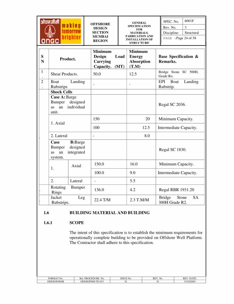
1.5.9 SPECIFIC REQIREMENT
The specific requirements of the various rubber products for the system
design given in the bid package along with Base Specification / Product
trademarks are given below:-
FORMAT No. Ref. PROCEDURE No. ISSUE No. REV. No. REV. DATE:
ODS/SOF/004B ODS/SOP/008 TO 015 01 01 15/10/2003
OFFSHORE
DESIGN
SECTION
MUMBAI
REGION
GENERAL
SPECIFICATION
FOR
MATERIALS,
FABRICATION AND
INSTALLATION OF STRUCTURE
SPEC. No. 6001F
Rev. No. 3
Discipline: Structural
PAGE :Page 24 of 58
1.6 BUILDING MATERIAL AND BUILDING
1.6.1 SCOPE
The intent of this specification is to establish the minimum requirements for
operationally complete building to be provided on Offshore Well Platform.
The Contractor shall adhere to this specification.
S
N Product.
Minimum
Design Load
Carrying
Capacity. (MT)
Minimum
Energy
Absorption
(T.M)
Base Specification &
Remarks.
1
. Shear Products. 50.0 12.5
Bridge Stone SC 500H,
Grade Ro.
2
.
Boat Landing
Rubstrips - -
EPI Boat Landing
Rubstrip.
Shock Cells
Case A: Barge
Bumper designed
as an individual
unit.
Regal SC 2036.
150 20 Minimum Capacity.
1. Axial
100 12.5 Intermediate Capacity.
2. Lateral - 8.0
Case B:Barge
Bumper designed
as an integrated
system.
Regal SC 1830.
150.0 16.0 Minimum Capacity. 1.
Axial
100.0 9.0 Intermediate Capacity.
3.
2. Lateral - 5.5
4. Rotating Bumper
Rings 136.0 4.2 Regal RBR 1931.20
5. Jacket Leg
Rubstrips. 22.4 T/M 2.3 T.M/M
Bridge Stone SA
300H Grade R2.
FORMAT No. Ref. PROCEDURE No. ISSUE No. REV. No. REV. DATE:
ODS/SOF/004B ODS/SOP/008 TO 015 01 01 15/10/2003
OFFSHORE
DESIGN
SECTION
MUMBAI
REGION
GENERAL
SPECIFICATION
FOR
MATERIALS,
FABRICATION AND
INSTALLATION OF STRUCTURE
SPEC. No. 6001F
Rev. No. 3
Discipline: Structural
PAGE :Page 25 of 58
1.6.2 GENERAL
1.6.2.1 GENERAL REQUIREMENTS.
1.6.2.1.1 Contractor shall fabricate a building on the platform to facilitate Switchgear
Room, Telemetry Room, Battery Room & Generator Room and other
necessary room as specified in the scope of work. Contractor is responsible
for complete design including all structural framing.
1.6.2.1.2 Equipment, as specified elsewhere in bid package, shall be supplied and
installed in the rooms of the building.
1.6.2.1.3 Contractor shall furnish other facilities and equipment, both inside and
outside the building as required in these specifications.
1.6.2.1.4 All material, equipment, tools or supplies to be incorporated permanently
into the building shall be new, sound, free from all defects and confirm to
the size and /or capacity and quality specified. Contractor shall, when
required, furnish satisfactory evidence as to the type and quality of
materials, equipment, tools and supplies.
1.6.2.1.4.1 Contractor shall notify Company Representative of any aspect of this
specification, which in the judgment of the Contractor should be changed to
improve the buildings. However, the incorporation of these changes into this
specification is subject to Company’s approval.
1.6.2.2 BUILDING REQUIREMENT
The items listed outline the general requirement for various buildings:
1.6.2.2.1.1 The building shall be suitable for occupancy and general usage in a marine
environment and suitable for environmental condition as indicated in the
bid.
1.6.2.2.2 The building shall be planned and design by Contractor with suitable wall,
partition, interior partitions, interior and exterior doors with frames and
windows etc.
1.6.2.2.3 The building shall have framed openings in walls and roof for equipment,
piping, cables exhaust etc. as required.
1.6.2.2.4 The buildings shall be completely wired for lighting receptacles, switches
and equipment.
FORMAT No. Ref. PROCEDURE No. ISSUE No. REV. No. REV. DATE:
ODS/SOF/004B ODS/SOP/008 TO 015 01 01 15/10/2003
OFFSHORE
DESIGN
SECTION
MUMBAI
REGION
GENERAL
SPECIFICATION
FOR
MATERIALS,
FABRICATION AND
INSTALLATION OF STRUCTURE
SPEC. No. 6001F
Rev. No. 3
Discipline: Structural
PAGE :Page 26 of 58
1.6.2.2.5 Piping and electrical connections shall be arranged such that field
connections are minimized.
1.6.2.2.6 The building shall be furnished completely operational prior to load-out.
1.6.2.2.7 The area classification outside/inside the building shall be as per relevant
specifications.
1.6.3.0 STRUCTURAL SPECIFICATIONS
1.6.3.1 MATERIAL
Structural Steel shall be as per specification stated in clause no. 1.1 of this
document.
1.6.3.2 DESIGN
The building shall be designed in accordance with Section.3.4, Structural
Design Criteria.
1.6.3.3 FABRICATION
Fabrication of the Structure shall be in accordance with clause no 2.0 of this
specification.
1.6.3.4 COATING SYSTEM
All exposed structural steel shall be coated in accordance with General
Specification No. 2005, Protective Coatings. The Contractor shall keep
adequate paint material for field touch-up after installation.
1.6.4.0 ARCHITECTURAL SPECIFICATIONS
1.6.4.1 ROOF AND WALLS
1.6.4.1.1 General
The building shall be properly enclosed, with steel wall and roof, joints and
openings shall be sealed against penetration and to reduce thermal
conductivity.
The building materials and construction shall confirm to the requirements of
the NFPA “National Codes”.
1.6.4.1.2 Walls shall be made up of 6 mm thick plate, suitably reinforced and painted.
The roof if comes under helideck shall have a 6 mm thick plate welded to
FORMAT No. Ref. PROCEDURE No. ISSUE No. REV. No. REV. DATE:
ODS/SOF/004B ODS/SOP/008 TO 015 01 01 15/10/2003
OFFSHORE
DESIGN
SECTION
MUMBAI
REGION
GENERAL
SPECIFICATION
FOR
MATERIALS,
FABRICATION AND
INSTALLATION OF STRUCTURE
SPEC. No. 6001F
Rev. No. 3
Discipline: Structural
PAGE :Page 27 of 58
the underside of beams such that there is a clear air gap is maintained for
passage of air. 1.6.4.1.2.1 Steel metal for flashing and other closures shall be 14-gauge steel. Interior
wall liner and interior partition shall be of non-combustible materials. All
closures in walls and roof shall form a non-combustible, watertight seal
around service lines electrical cables, etc. Use of multi-cable transists or
other UL approved fire stop methods shall be considered for all cables
entering or leaving the building. For Telemetry Room one cable entry plate
of size 1m X 0.8m shall be provided.
1.6.4.1.3 Finish: All surface finish marks and scratches shall be touched up to match
the original coating.
1.6.4.1.4 Suspended Ceiling
General: Contractor shall furnish and install the suspended ceiling at least
in Telemetry and shelter (living) room, complete with suspension system,
related accessories and light fixtures wherever indicated.
Construction: The suspended ceiling shall consist of removable panels of
backed enamel painted / galvanized steel sheet installed on a standard
electro-galvanised steel exposed grid system.
Main runners shall be suspended using no.12 gauge galvanized wire hangers
and spaced a maximum of 1200 mm. A matching metal molding shall be
installed at the periphery of all areas. The suspension system shall be a fire-
rated assembly as listed by the Underwriter’s Laboratory, Inc.
Acoustic panel shall be non combustible material having fire spread
characteristics confirming to Class-I surface spread of flame as per BS476
Part-VII:1971 or equivalent FSI as per NFPA 255.
Necessary cutouts shall be made in the ceiling to house recessed type
luminaries. The luminaries shall be supported by the framing.
Finish: Acoustical panels shall have a factory applied fire resistant paint
finish having a light reflectance’s of 0.80.
The metal suspension system and all exposed metal parts shall have a fire-
resistant paint finish.
1.6.4.2 FLOORING
1.6.4.2.1 General: Contractor shall furnish and install flooring with rigid or resilient
material, which shall confirm to Class – I surface spread of flame as per BS
FORMAT No. Ref. PROCEDURE No. ISSUE No. REV. No. REV. DATE:
ODS/SOF/004B ODS/SOP/008 TO 015 01 01 15/10/2003
OFFSHORE
DESIGN
SECTION
MUMBAI
REGION
GENERAL
SPECIFICATION
FOR
MATERIALS,
FABRICATION AND
INSTALLATION OF STRUCTURE
SPEC. No. 6001F
Rev. No. 3
Discipline: Structural
PAGE :Page 28 of 58
476 Part-VII or equivalent FSI as per NFPA 255, over the entire floor area
of the building except where otherwise noted.
The switchgear room floor shall be provided 5.56 mm (7/32 inch) thick
heavy duty ribbed rubber floor mating in front of equipment and main traffic
areas. (The mat shall be cut and installed so that it may be easily removed
for washing) slotted channel wit cover strips (Unistrut P-1000 & P-1184 or
equivalent) shall be provided in the telemetry room flooring to facilitate to
future installation of telemetry/ telecontrol equipments by others. Floor tiles
shall be provided to finish the flooring flush the channel.
The battery room floor shall be furnished with pure Epoxy paint of non-skid
type. Thickness of coating and application procedure shall be as per
manufacturers recommendation.
1.6. 4.3 DOOR AND DOOR FRAMES
1.6.4.3.1 General: Contractor shall furnish and install all door frames, doors,
stainless steel hardware as required for complete installation, including
threshold and weather stripping.
1.6.4.3.2 DOOR CONSTRUCTION:
Door shall be of standard dimension.
Door shall be properly reinforced for all hardware
Door shall be free from wrap or buckles
Exterior door shall be made of steel and weld joints shall be ground smooth.
Door shall have three ball bearing hinges of standard weights stainless steel
of minimum 114 mm X 114 mm size. Actual size to be provided according
to the functional and design requirement
Interior shall be furnish with stainless steel latches for operation from inside
and outside
All external door shall be furnished with panel latches on the inside, push
down to and latch type. The leaf shall be furnished with mortise exit device
(Underwriter Laboratory Inc. approved).
All external doors shall be provided with continuous rubber bidding with
heavy duty rubber of sufficient thickness and width all along the periphery
of the door frame, which in contact with the door leaf in closed position. All
hardware shall be stainless steel 316
1.6.4.3.3 Door frame construction: Door frame shall be combination buck and jamb
and of same material as doors. Door frames for steel Door shall be made of
FORMAT No. Ref. PROCEDURE No. ISSUE No. REV. No. REV. DATE:
ODS/SOF/004B ODS/SOP/008 TO 015 01 01 15/10/2003
OFFSHORE
DESIGN
SECTION
MUMBAI
REGION
GENERAL
SPECIFICATION
FOR
MATERIALS,
FABRICATION AND
INSTALLATION OF STRUCTURE
SPEC. No. 6001F
Rev. No. 3
Discipline: Structural
PAGE :Page 29 of 58
14-gauge steel. Millers shall be accurate exposed wielding shall be ground
smooth
Door frames shall be reinforced for all hardware with No. 7 gauge steel
Threshold and weather’ stripping: All exterior Doors shall be furnished
threshold and weather stripping appropriate to withstand condition as
specified in Section 3.4 and Basic Environment Conditions as per Clause
3.1.2, Section 3.1of Design Criteria.
1.6.4.3.4 Finish: Doors & doors frames shall be coated in accordance with general
Specification 2005, Protective Coating.
All marks and scratches shall be touched up to match the original finish of
doors and frames.
1.6.4.4 WINDOWS
1.6.4.4.1 General: Contractor shall furnish and install all windows, window frames,
glass, caulking compound etc. as required for a complete installation.
1.6.4.4.2 Construction: Windows shall be suitably located and sized. All windows
shall be fixed, non-opening type with shatter proof, wire reinforced
toughened glass of minimum 6 mm thickness.
Windows shall be provided with anodized aluminum frames.
Windows frames shall be set plumb, true and in alignment. Full mastic bead
shall be provided at all sills, mullions and aluminum contact surfaces.
Glass shall be transparent, tinted, shatterproof wire reinforced toughened
glass of minimum 6 mm thickness.
Caulking compound shall be non-staining, elastic, water proof and non-
corrosive.
Louvered windows, in non hazardous, area shall be of suitable dimensions
for adequate natural ventilation.
1.6.4.5 FURNISHING & ACCESSORIES
Shelter room (accommodation) shall be provided with accommodation for
two persons with furniture like foldable cots with beds and pillows, 2 (two)
numbers tables and 4 (four) nos. of light weight chairs. The cot shall be
hinged on wall on one long side of bed and the other long end shall be
suitably hung or with supporting arrangement.
FORMAT No. Ref. PROCEDURE No. ISSUE No. REV. No. REV. DATE:
ODS/SOF/004B ODS/SOP/008 TO 015 01 01 15/10/2003
OFFSHORE
DESIGN
SECTION
MUMBAI
REGION
GENERAL
SPECIFICATION
FOR
MATERIALS,
FABRICATION AND
INSTALLATION OF STRUCTURE
SPEC. No. 6001F
Rev. No. 3
Discipline: Structural
PAGE :Page 30 of 58
1.6.5.0 TESTING
1.6.5.1 In accordance to the testing requirements shall be as per Codes & Standards,
testing of the electrical, piping systems, all equipment, and all other
components (windows, doors, switches, etc.) shall be affected after
fabrication onshore and prior to acceptance.
1.6.5.2 Testing shall be done in accordance with the applicable equipment
specifications.
1.6.5.0 PREPARATION FOR SHIPMENT
1.6.5.1 GENERAL
Where applicable, preparation for shipment shall be performed in
accordance to the specifications proposed in this specification under
Installation.
1.6.5.2 TEMPORARY BRACING
Contractor shall provide temporary bracing for all equipment and furnishing
to ensure their stability during transportation, shipping and handling of the
building. While bracing must be strong enough for this purpose, it should be
designed for easy removal with no damage to any portion of the building
once it is securely set in its final location.
2.0 FABRICATION
2.1 SCOPE
These specifications provides for functional specification of fabrication of
structures including few specific requirements/ guidelines.
2.2 GENERAL
The fabrication of platform including fit-up, welding, assembly, QA/QC
pre-commissioning etc .shall be carried out as per provisions of API RP 2A,
AWS D1.1 and AISC (American Institute of Steel Construction).
Contractor to furnish a detailed procedure for fabrication and assembly of
structure for Company’s review which shall include following as a
minimum.
1. Procedure for fabrication and assembly.
FORMAT No. Ref. PROCEDURE No. ISSUE No. REV. No. REV. DATE:
ODS/SOF/004B ODS/SOP/008 TO 015 01 01 15/10/2003
OFFSHORE
DESIGN
SECTION
MUMBAI
REGION
GENERAL
SPECIFICATION
FOR
MATERIALS,
FABRICATION AND
INSTALLATION OF STRUCTURE
SPEC. No. 6001F
Rev. No. 3
Discipline: Structural
PAGE :Page 31 of 58
2. Procedure for fit-up and welding.
3. Procedure for dimension control.
4. Procedure for inspection and testing
5. QA/QC plan.
6. Procedure for Pre-commissioning.
7. Procedure for post installation checks.
8. Health Safety & Environment Manual.
9. Procedure for Painting and galvanization
10. Procedure for Post weld heat treatment
11. Procedure for Defect repair and Distortion control
12. Procedure for material traceability
13. Procedure for material receipt, Inspection and storage.
14. Weighing procedure
2.3 SPECIFIC REQIREMENT
Following specific requirement shall be complied with:
2.3.1 Manufacture of tubular structural members
Tubular of diameter greater than 406 mm shall be rolled from plates in
accordance with API Spec. 2B.
The tubular shall be rolled in an API approved mill and shall carry the API
monogram.
The tubular shall be longitudinal seam welded by electric submerged are
process. Electric resistance welded or spiral welded pipes will not be
accepted. Pipes shall have only one longitudinal seam weld. The welding
and weld inspection shall be as per the Specification No.2009 and relevant
Codes and Standards.
The tubular shall meet the requirements of API Spec. 2B with the following
exceptions:
a. The wall thickness and weight tolerances for tubular members shall be
governed by the requirements of the code under which the plates are
rolled.
b. For girth joints with offsets greater than 1.5 mm, the following shall
apply:
i. When cans are of different thickness the higher thickness shall be
ground smooth or machined to provide a 2.5: 1 taper transition.
FORMAT No. Ref. PROCEDURE No. ISSUE No. REV. No. REV. DATE:
ODS/SOF/004B ODS/SOP/008 TO 015 01 01 15/10/2003
OFFSHORE
DESIGN
SECTION
MUMBAI
REGION
GENERAL
SPECIFICATION
FOR
MATERIALS,
FABRICATION AND
INSTALLATION OF STRUCTURE
SPEC. No. 6001F
Rev. No. 3
Discipline: Structural
PAGE :Page 32 of 58
ii. When cans are of same thickness, the offset shall be tapered to a
slope of 4: 1 by deposit of additional weld metal and ground
smooth.
In no case shall the metal thickness be less than the nominal thickness
of the thinner can. Maximum offset permissible shall be governed by
Clause 3.7 of the API Spec. 2B.
2.3.2 Galvanizing.
Following structural shall be galvanized as per General Specification No.
2005 “Protective coating”.
Gratings.
Handrails.
Stair Treads, Ladders and ladder cages.
Helideck Safety Net System.
Miscellaneous hardware.
Galvanizing shall be done after completion of all cutting, drilling and
punching operations and after welding but before final assembly in place.
Painting
All painting shall be done as per General Specification No. 2005 “Protective
coating”.
Contractor shall mark levels suitably with paints to facilitate assessment of
levels during and after upending and placement of sub-structure at location.
Jacket and Pile shall be foot marked at 120º apart which should cover at
least half the circumference. This is to facilitate the checking during the
uppending of the Jacket and pile driving. All under water clamps shall be
painted with white paint.
2.3.3 Marking of low-fatigue joint
Marking of low fatigue life joints for future inspection shall be carried out as
described in Design Criteria Structural. The marking panel of neoprene
based cupronickel embedded sheets shall be at least 400 mm wide and shall
have a length corresponding to number of letters in the marking. Each letter
shall be located in the space of 200 mm x 200 mm size with a letter width of
40 mm. Lettering shall be with a medium suitable to withstand marine
FORMAT No. Ref. PROCEDURE No. ISSUE No. REV. No. REV. DATE:
ODS/SOF/004B ODS/SOP/008 TO 015 01 01 15/10/2003
OFFSHORE
DESIGN
SECTION
MUMBAI
REGION
GENERAL
SPECIFICATION
FOR
MATERIALS,
FABRICATION AND
INSTALLATION OF STRUCTURE
SPEC. No. 6001F
Rev. No. 3
Discipline: Structural
PAGE :Page 33 of 58
environment. A border of 100 mm shall be provided all round the lettering.
Marking shall be provided in the form of a strip.
2.3.4 Repair and remedial measures
Repair of defects and acceptability shall be as per API RP-2A. Welding
repair, if any, shall be performed only after approval of the Company.
2.3.5 Connections
2.3.5.1 Welded Connections
All structural welds shall be full penetration welds unless otherwise
specifically shown in the drawing. Partial penetration welds are not
permitted.
2.3.5.2. Bolted Connections
As a general rule bolted connections shall not be used unless specifically
indicated. Use of bolted connections for temporary works may be permitted
by the Company’s representative at site at his sole discretion. Contractor to
submit detail procedure for bolting for approval of Company.
2.3.6 Splices
a. Tubular member of the same diameter and wall thickness may be
spliced by girth butt weld, as per provisions of API Spec. 2B with the
following additions:
All joint cans length up to 3 M shall be rolled in one section. Joint
cans with a length greater than 3 m must be made-up of sections
limited to 1.5 m minimum length. In no case shall the girth weld/fall
within 75 mm on either side of crown and saddle point.
b. Beam splices shall be as per API RP 2A with the following additions:
splices for deck beams must be staggered i.e. the splices in any two
adjacent beams shall not lie in a line perpendicular to the beam axis.
c. Joints in bar gratings and deck plate in the span direction shall occur
only at points of structural support. All plating shall be continuously
seal welded to supporting members.
d. Deck plating shall be welded in place using a low heat, short arc
welding process. This requirement is to minimize potential warping of
the deck plates and to obtain optimum levelness of the deck surface.
FORMAT No. Ref. PROCEDURE No. ISSUE No. REV. No. REV. DATE:
ODS/SOF/004B ODS/SOP/008 TO 015 01 01 15/10/2003
OFFSHORE
DESIGN
SECTION
MUMBAI
REGION
GENERAL
SPECIFICATION
FOR
MATERIALS,
FABRICATION AND
INSTALLATION OF STRUCTURE
SPEC. No. 6001F
Rev. No. 3
Discipline: Structural
PAGE :Page 34 of 58
Other low heat, time saving or automatic welding procedure may be
considered but must be qualified.
2.3.7.1 Stress relieving.
1. Rolled Tubular with outer diameter to thickness ratio less than 20 shall
be stress relieved after manufacture.
2. Welded assemblies, where the thickness of one of the elements
exceeds 65 mm, or where the thickness of weld exceeds 50 mm shall
be stress relieved after assembly.
3. Any other element/assembly specifically noted in the drawings shall
be stress relieved.
All stress relief shall be achieved by thermal methods by heating the
element or assembly to a temperature between 590° C and 620°C. The use
of furnaces is desirable for all stress relief operations. A detailed procedure
shall be developed and Company’s approval obtained prior to performing
the operations.
2.3.7.2 Fabrication tolerances
Fabrication tolerances shall be as per API-RP-2A, AWS D.1, AISC, API
5L and API 2B wherever applicable. Fabrication tolerances for structural
shapes fabricated from plates shall conform to the requirements of ASTM
A6.Contractor shall use his best efforts to provide a flat deck surface. All
high or low spots that result during the installation of deck plating/grating
and after installing skids and equipment shall be eliminated to reduce water
holding valleys to a maximum of 3 mm.
2.3.8 Inspection And Testing For Structural Fabrication
a. The Company shall inspect fabrication and assembly of structures
stage wise and after final completion.
b. The Company shall have the right to inspect the materials, fabrication
and erection of all items concerned with the works without limitation.
c. The Company shall have free access at all times to any part of
Contractor’s yard that concerns the work. When in the Company
judgment, any working area or section should be inspected, the
Contractor must thoroughly clean it of all excess and waste materials
such as sand , slag, welding rods etc, and allow adequate time for
proper inspection .
FORMAT No. Ref. PROCEDURE No. ISSUE No. REV. No. REV. DATE:
ODS/SOF/004B ODS/SOP/008 TO 015 01 01 15/10/2003
OFFSHORE
DESIGN
SECTION
MUMBAI
REGION
GENERAL
SPECIFICATION
FOR
MATERIALS,
FABRICATION AND
INSTALLATION OF STRUCTURE
SPEC. No. 6001F
Rev. No. 3
Discipline: Structural
PAGE :Page 35 of 58
d. The Company shall be informed at least ten days prior to starting of
any work by Contractor or any sub-Contractor such as assembling or
fabrication of any section, grit blasting, painting etc. The Company
shall be informed before any repairs are made to the welds when
defects are found and not after same defects have been rectified.
Whenever any piece is to be assembled that will prevent inspection of
the area, Company shall be informed, the area inspected and any
defects rectified before proceeding with the assembly.
e. The Company shall have the right to inspect at any time tools or
equipments to be used in any part of the work and shall have the right
to condemn any equipment or work which do not conform to the
specification or the drawings. Defective work or work not conforming
to the specifications or the drawing shall be re-done by the Contractor
at his cost.
f. Company shall approve all phases of the testing including leak repair
or defects and replacement of materials and equipments found to be
defective during testing and shall sign all Test Certificates, if testing is
witnessed by the Company.
g. The Company shall have the right to request any additional inspection
to ensure that the Work conforms to the specifications, at no extra cot
to the Company.
h. The Contractor shall furnish, install and maintain in a safe operating
condition all scaffolding, ladders, walk ways, adequate lighting etc.
necessary for safe and thorough inspection by Company. The safety
and condition of above scaffolding, ladders, lighting etc. must conform
with local industrial safety codes for such operations.
i. The Contractor must ensure that all valves and removable plugs on
jacket legs are closed prior to load out and shall give written
certification for the same.
j. After the fabrication is completed, the jacket legs and skirt sleeves,
pre-installed conductors and pile sections, launch truss chords and
buoyancy tank, if any, shall be pressure tested for leaks through top
and bottom closures. The applied pressure shall be 1.5 Kg/cm2
minimum and maintained for four hours. A soap test shall be
conducted to detect any leakage between the rubber diaphragm and the
flange and top closure plates and welds or any other joints. A nominal
positive pressure shall be left in the jacket and skirt sleeve to ensure no
leak condition before launching. All inflatable packers shall be
pressure tested again at the yard to the test pressure specified.
FORMAT No. Ref. PROCEDURE No. ISSUE No. REV. No. REV. DATE:
ODS/SOF/004B ODS/SOP/008 TO 015 01 01 15/10/2003
OFFSHORE
DESIGN
SECTION
MUMBAI
REGION
GENERAL
SPECIFICATION
FOR
MATERIALS,
FABRICATION AND
INSTALLATION OF STRUCTURE
SPEC. No. 6001F
Rev. No. 3
Discipline: Structural
PAGE :Page 36 of 58
The manufacturer’s test certificate shall be furnished to the Company.
k. All grout and air lines for the jacket grouting system shall be cleaned
by blowing clean air to ensure their operatability. These shall be
pressure tested at 40 Kg/cm2
for one hour. The protective housing at
the bottom of jacket for the inflate lines shall also be pressure tested to
the above pressure.
2.3.9 Pre-commissioning checks
After the fabrication yard erection and hook-up has been completed, the
Contractor shall start the pre-commissioning checks. It may not be possible
to complete all the pre-commissioning checks in the fabrication yard. A
detailed list of pre-commissioning checks required to be performed by the
Contractor are specified in the bid documents. However, the Company
desires that at least the following pre-commissioning checks/tests shall be
completed in the fabrication yard.
Contractor to note that installation check as called out in the following list
shall include the following
1. Name - plates and/ or certificates of equipment are correct and visible.
2. Equipments are properly installed in accordance with drawings and
foundations are proper.
3. All necessary supports are attached and are in acceptable condition.
4. All connections of equipment to piping, tubing and wiring are made in
accordance with drawings and specifications.
5. All low fatigue joints are properly marked.
6. List of out of tolerance reports.
a. Lifting equipment (Cranes, Hoists etc.)
1. Installation check.
2. Loads tests.
3. Function check of alarm points in the control cab.
FORMAT No. Ref. PROCEDURE No. ISSUE No. REV. No. REV. DATE:
ODS/SOF/004B ODS/SOP/008 TO 015 01 01 15/10/2003
OFFSHORE
DESIGN
SECTION
MUMBAI
REGION
GENERAL
SPECIFICATION
FOR
MATERIALS,
FABRICATION AND
INSTALLATION OF STRUCTURE
SPEC. No. 6001F
Rev. No. 3
Discipline: Structural
PAGE :Page 37 of 58
b. Decks, Building and Accessories.
1. Installation check.
2. Water flood check of flooring and roofs against leaks and
stagnation.
2.3.10 Weighing of decks/modules and other top sides facilities.
The Contractor, prior to load out, shall accurately weight all Deck
structures, topside modules & buildings, and other topsides facilities etc.
Contractor shall include in his proposal the basic details of the weighing
procedure and equipments intended to be used. Detailed weighing
procedures shall be developed and submitted for Company’s approval upon
award of Contract. Load cells used shall have valid calibration Certificates.
While weighing it shall be noted that the point of application of the load
cells shall be in such a manner that based on the results of the weighing it
shall be possible to devise the reactions at each support point as well as the
center of gravity of the component being weighed.
Contractor shall prepare a procedure for final weighing report for
every lift containing.
i. Weighing Results.
ii. Theoretical Prediction.
iii. Item schedule for all items which are yet to be installed prior to lifting,
together with any items, which are to be removed i.e. rigging platform
etc.
Contractor shall assume full responsibility for all remedial measures
required as a result of weight escalation beyond the weights budgeted for
sea-transport, offshore lifting and final service operations. This
responsibility shall include but not be limited to revision of the marine
spread, strengthening and stiffening of the structures, off loading
components in that lift etc.
FORMAT No. Ref. PROCEDURE No. ISSUE No. REV. No. REV. DATE:
ODS/SOF/004B ODS/SOP/008 TO 015 01 01 15/10/2003
OFFSHORE
DESIGN
SECTION
MUMBAI
REGION
GENERAL
SPECIFICATION
FOR
MATERIALS,
FABRICATION AND
INSTALLATION OF STRUCTURE
SPEC. No. 6001F
Rev. No. 3
Discipline: Structural
PAGE :Page 38 of 58
3.0 INSTALLATION
3.1 SCOPE
The specification assumes that piled steel jacket structures for the Platform
Structure has been proposed by the Contractor and approved by the
Company.
This specification described the minimum technical requirements for the
engineering, marine and construction equipment spreads and operations
required for the load out, transportation and installation of the Platform and
facilities.
The Contractor shall assume entire responsibility for the successful load out,
sea-fastening and transportation to site of all material, structures,
components, equipment and other items necessary for installation and for
satisfactorily completing all installations including hook-up and
commissioning work, notwithstanding any review by the Company.
3.2 QUALITY MANAGEMENT AND DOCUMENTATION
3.2.1 Project Planning and Execution
Load out, transportation and installation operations shall be planned and
executed in accordance with the requirements of the Contract and the DNV
Rules for planning and Execution of Marine Operations. Release Note of
Inspection agency, on behalf of Company, at fabrication yard shall be
obtained and which shall be made available to Company at Offshore
Installation site.
3.2.2 Verification
The verification record control and retention system shall ensure documents
relevant to obtaining Certifying Authority approvals are retained.
3.2.3 Installation Engineering Manual
An Installation Engineering Manual shall be compiled, covering all aspects
of the transportation and installation of the platform component structures,
including mobilization of transportation and installation vessels spreads.
The installation Manual shall contain detailed information on each stage of
the operation, including contingency procedures and shall identify
temporary works, equipment and personnel requirements.
FORMAT No. Ref. PROCEDURE No. ISSUE No. REV. No. REV. DATE:
ODS/SOF/004B ODS/SOP/008 TO 015 01 01 15/10/2003
OFFSHORE
DESIGN
SECTION
MUMBAI
REGION
GENERAL
SPECIFICATION
FOR
MATERIALS,
FABRICATION AND
INSTALLATION OF STRUCTURE
SPEC. No. 6001F
Rev. No. 3
Discipline: Structural
PAGE :Page 39 of 58
The installation Manual shall include but not be limited to the following
contents, as appropriate
a) General
• Organization charts for Load out site(s) and offshore site.
• Vessel utilization schedule
• Schedule for transportation and installation operations
• Offshore support base details.
• Mobilization and Demobilization activities.
b) Vessel Data
• Derrick Vessels
• Support Vessels
• Transportation vessels (Cargo barges and tow vessels or HLV)
c) Load out
• Load out site details and activities
• Planning for the load out phase
• Ballasting execution plans
• Barge strengthening or reinforcement (if required)
• Load distribution mats (if required)
• Sea fastenings
d) Transportation
• Pre-Sail away inspection checklists
• Towing/transit plans, towing arrangements, ballast arrangements,
navigational aids, communications procedures, contingency
procedures, etc.
• Tow/ transit routes, including any alternative and proposed safe
refuges.
• Proposed dates for sail away, tow/transit, and installation.
• Weather forecasting and weather limits for sail away and
tow/transit.
• Repair procedures during tow/transit and at completion of
tow/transit
• Post tow/transit inspection checklists.
e) Installation
• Offshore site Preparations
• Locations for existing subsea pipelines
FORMAT No. Ref. PROCEDURE No. ISSUE No. REV. No. REV. DATE:
ODS/SOF/004B ODS/SOP/008 TO 015 01 01 15/10/2003
OFFSHORE
DESIGN
SECTION
MUMBAI
REGION
GENERAL
SPECIFICATION
FOR
MATERIALS,
FABRICATION AND
INSTALLATION OF STRUCTURE
SPEC. No. 6001F
Rev. No. 3
Discipline: Structural
PAGE :Page 40 of 58
• Location and orientation of existing jackets and other structures
• Installation equipment spread details
• Detailed installation procedures and checklists for structures,
including tow/transportation vessel handling, derrick vessel
anchor plans, survey, drilling and grouting procedures etc.
• Maximum sea states and weather conditions for weather
installation operations
• Jacket launch/lift and up - ending, pile installation, jacket
leveling procedures.
• Installing boat landing, barge bumpers, fitting and welding pump
casing, sumps etc.
• Topside module installation procedures
• Removing temporary braces, lift trunnions, sea fastenings
• Installing all jackets to deck piping and utilities shown on
drawings.
• Post – installation activities and inspection check lists.
• Platform hookup activities.
f) Contingency Plans
• Procedures for bad weather conditions
• Contingency procedures for piling operations, including storm
ballast plan for the jacket if piling must be abandoned due to
weather before storm safe.
g) Quality
• Site – specific Quality plan, including ITPs.
• Qualified weld procedures and welder qualification records
• Installation activity proformas (pile driving records, grouting
records etc.)
h) Health, Safety & Environment
• Contractor HSE Plan, including JHA action sheets
• Emergency Response Plan for the Offshore site.
i) Drawings and Calculations
• Installation Schematics
• Derrick vessels equipment layouts
• Cargo barge stability and ballasting calculations and details
• Temporary works layout
• Cargo barge or HLV layouts
FORMAT No. Ref. PROCEDURE No. ISSUE No. REV. No. REV. DATE:
ODS/SOF/004B ODS/SOP/008 TO 015 01 01 15/10/2003
OFFSHORE
DESIGN
SECTION
MUMBAI
REGION
GENERAL
SPECIFICATION
FOR
MATERIALS,
FABRICATION AND
INSTALLATION OF STRUCTURE
SPEC. No. 6001F
Rev. No. 3
Discipline: Structural
PAGE :Page 41 of 58
• Anchor patterns and existing subsea pipeline locations
• Sea fastening and grillage layouts and details
• Jacket on-bottom weight and mud mat reaction pressures
• Weight and Centre of Gravity data for all installed items
• Relevant structure drawings
3.2.4 Certification
Material Certificates shall be provided for all materials used for both
temporary and permanent works, including at least for the following
• Temporary load bearing attachments
• Lift rigging
• Welding consumables
• Cement
• Coatings
3.2.5 Traceability
Traceability records shall be provided and maintained for –
• Material heat numbers
• Welding consumable batch numbers
• Weld procedure numbers
• Welder identification numbers
• NDT reference
• Post weld heat treatment records
• Weld repairs
3.2.6 Manufactures Data Report
Documentation for welding to any part of a structure and all over as-built
data shall be complied into a MDR, which shall contain the following as a
minimum, a appropriate –
• Approved welding procedures
• Welder qualification records
• Approved NDT procedures and NDT personnel qualification records
• Traceability records
• Material test certificates
• Welding consumable test certificates
• NDT records
• Post weld heat treatment records
• Dimensional control records
FORMAT No. Ref. PROCEDURE No. ISSUE No. REV. No. REV. DATE:
ODS/SOF/004B ODS/SOP/008 TO 015 01 01 15/10/2003
OFFSHORE
DESIGN
SECTION
MUMBAI
REGION
GENERAL
SPECIFICATION
FOR
MATERIALS,
FABRICATION AND
INSTALLATION OF STRUCTURE
SPEC. No. 6001F
Rev. No. 3
Discipline: Structural
PAGE :Page 42 of 58
• Site preparation details
• Survey and inspection records
• Underwater inspection records (including video if available)
• Pile diving records
• Grouting records
• Hook-up activities quality records
• Engineering calculations and analysis results
• Technical manuals
• Basis of Design
3.2.7 As-Built Report
The Offshore platform As-Built Report shall comprise the MDR and a
summary of all work performed. Non-MDR documentation shall include but
not limited to the following –
• Daily Tow/Transit Reports
• Daily progress Reports from derrick vessels at the offshore site.
• Transportation and installation programme (actual versus planned)
• Record of mobilization activities
• Record of loadout site activities
• Vessel utilization schedule (actual)
• HSE Report
• Contract Variations
In each section, manning levels, durations, problems, encountered,
highlights and the like shall be included.
3.3 HEALTH & SAFETY AND ENVIRONMENTAL MANAGEMENT
i. All transportation and installation activities shall be planned and
executed to minimize risk to personnel health and safety and to the
environment, in compliance with the HSE Plan.
All statutory regulations at the load out site, along the tow/transit route and
at the offshore site shall be complied with, including –
a) SOLAS requirements
b) IMO Convention on the international Regulations for Preventing
Collisions at Sea (COLREG), 1972 and Amendments.
c) IMO MARPOL 73/78 and Amendments (including The International
Convention for the Prevention of Pollution from Ships).
FORMAT No. Ref. PROCEDURE No. ISSUE No. REV. No. REV. DATE:
ODS/SOF/004B ODS/SOP/008 TO 015 01 01 15/10/2003
OFFSHORE
DESIGN
SECTION
MUMBAI
REGION
GENERAL
SPECIFICATION
FOR
MATERIALS,
FABRICATION AND
INSTALLATION OF STRUCTURE
SPEC. No. 6001F
Rev. No. 3
Discipline: Structural
PAGE :Page 43 of 58
ii. Contractor shall submit the copies of following documents and
latest/valid survey certificates in respect of all vessels proposed by the
Contractor for transportation/installation/towing in compliance with General
Condition of Contract.
Certificate of Registry, Certification of Classification, Certificate of
Class, Cargo Ship Safety Construction Certificate, Cargo Ship Safety
Equipment Certificate, Cargo Ship Safety Radio Certificate, Safety
Management Certificate, International Oil Pollution Prevention Certificate,
International Load Line Certificate, International Tonnage Certificate, DG
Shipping Licence and Insurance Certificate.
3.4 LOADOUT
3.4.1 General
The method of loadout may involve skidding, trolleying or lifting of
structures. The structural integrity of the structures must be maintained
during loadout. Detailed structural analysis for loadout or lift analysis for
each loadout structure shall be undertaken to verify that structural member
stresses do not exceed API and AISC basic allowable during any stage of
the loadout. The loadout analyses shall include studies to determine the
allowable differential deflections at the structures support point, which shall
become the basis for deflections tolerances during loadout. If Contractor
proposes any change in the parameters or procedures from those considered
in the design, he shall carry out necessary engineering as detailed in
Structural Design Criteria to ensure that his procedures are workable.
Structural strength of barge shall also be checked.
3.4.2 Barge Ballasting and Structure Motions
The Loadout Supervisor shall have the authority to direct all barge ballasting
and structure motions during loadout.
3.4.3 Loadout Systems
Contractor shall furnish to Company, at least 30 days prior to
commencement of any load out operation, a load out procedure describing
in detail the procedure, supported by calculation and analysis to ensure the
compliance of design requirements, for the load out, including requirement
of equipment and accessories. Contractor shall also furnish to Company the
contingency pull back arrangement for retrieval of the structure during load
out if the load out requires to be suspended due to some emergency reasons.
Contractor shall also submit 30 days prior to commencement of load out,
FORMAT No. Ref. PROCEDURE No. ISSUE No. REV. No. REV. DATE:
ODS/SOF/004B ODS/SOP/008 TO 015 01 01 15/10/2003
OFFSHORE
DESIGN
SECTION
MUMBAI
REGION
GENERAL
SPECIFICATION
FOR
MATERIALS,
FABRICATION AND
INSTALLATION OF STRUCTURE
SPEC. No. 6001F
Rev. No. 3
Discipline: Structural
PAGE :Page 44 of 58
details of the shipment plan and final transportation analysis and sea-
fastening design as described in design criteria.
The design or specification of all load out system components and
temporary works items required for the operation, including, as appropriate
the following–
• Winch systems
• Jacking systems
• Anchor points
• Onshore Skid beams
• Barge strengthening
• Cranes
• Transporters
• Lift points and lift rigging
• Barge mooring system
3.4.4 Cargo Barge
The adequacy of the cargo barge for stresses caused by load-out shall be
verified, as will compatibility of dockside and barge arrangements for the
proposed load out.
The ballasting procedure shall include pump discharge requirements and
considerations of tidal variations during load out.
3.4.5 Equipment
All equipment and accessories involved in the skidding/lifting/trolleying of
the structures shall have the proper rating and are free of damage. Critical
mechanical equipment, such as ballast pumps, shall have 100% backup
system on standby.
3.4.6 Skid Beams
The procurement, fabrication and installation of any onshore runway
beams/skids and bulkhead barge transition beams shall be suitable to
loadout the structures onto the barge, as necessary.
3.4.7 Loadout plan
The Loadout Plan shall include barge ballasting requirements during loadout
and a step-by-step schedule of the loadout. Allowances for actual tidal
changes and current shall be included in the Loadout Plan.
FORMAT No. Ref. PROCEDURE No. ISSUE No. REV. No. REV. DATE:
ODS/SOF/004B ODS/SOP/008 TO 015 01 01 15/10/2003
OFFSHORE
DESIGN
SECTION
MUMBAI
REGION
GENERAL
SPECIFICATION
FOR
MATERIALS,
FABRICATION AND
INSTALLATION OF STRUCTURE
SPEC. No. 6001F
Rev. No. 3
Discipline: Structural
PAGE :Page 45 of 58
3.4.8 Verification of lifts
Where loadout is executed by lifting, the padeyes, hook shackles slings,
sling platforms or frames and the structural integrity of the lifted item shall
be verified. The Contractor shall procure, fabricate and install all padeyes,
slings and other aids necessary for lifting.
3.4.9 Weight Monitoring
The weight and center of gravity of the structures shall be accurately
reported during construction and weight monitoring reports shall be
submitted to the Company on a regular basis. The final weight control
report and the results of the weighing operation shall also be submitted. Any
weighing undertaken prior to loadout shall achieve an accuracy better than
±2%. The center of gravity shall also be determined from these monitorings.
3.4.10 Cargo Manifest
An inventory list of all items to be loaded out shall be prepared by
Contractor.
3.4.11 Post Loadout Inspections
After loadout onto cargo or launch barge is completed, if the component has
been lifted, all critical joint intersections near the padeye/lifting points on
the component shall be MPI/ dye-penetrant checked to ensure that no cracks
have occurred during loadout. Any defects shall be repaired.
3.5 GRILLAGE AND SEAFASTENING
3.5.1 Design
All sea fastening and support grillage design shall be in accordance with the
provisions of API RP 2A. The following shall be prepared –
a) Design calculations of the sea fastening and grillages.
b) Drawings showing layouts and details of grillage and sea fastening.
c) Details of any barge strengthening required for loadout or transportation.
3.5.2 Grillage and Sea fastening Installation
Grillages and sea fastening shall be welded in accordance with relevant
specification and shall be subject to 100% ultrasonic and magnetic particle
inspection.
FORMAT No. Ref. PROCEDURE No. ISSUE No. REV. No. REV. DATE:
ODS/SOF/004B ODS/SOP/008 TO 015 01 01 15/10/2003
OFFSHORE
DESIGN
SECTION
MUMBAI
REGION
GENERAL
SPECIFICATION
FOR
MATERIALS,
FABRICATION AND
INSTALLATION OF STRUCTURE
SPEC. No. 6001F
Rev. No. 3
Discipline: Structural
PAGE :Page 46 of 58
3. 6. LOADOUT AND SEAFASTENING INSPECTION
The Contractor and MWS shall conduct pre and post loadout tests and
inspections.
3.6.1 Pre Loadout Testing
Pre loadout testing of flood, buoyancy and vent systems of the jacket shall
be executed in accordance with specification.
Prior and following loadout sea fastening, where possible, all vent and flood
valves shall be checked several times by the Contractor to ensure easy
operation. Any interference shall be eliminated. Vent and floods valves
shall be left in the closed position and the valve handles shall be positively
secured to the jacket.
3.6.2 Post Loadout Inspection
All structures shall be visually checked after loadout to ensure no damage
has occurred during loadout operations.
3.6.3 Patch and Repair Damage
The Contractor shall patch and repair all damage to the structure and its
protective coatings, which occur during loadout and sea fastening.
3.6.4 Loadout Operation
An appropriate ballast system shall be provided and experienced personnel
shall supervise the ballasting operation. The cargo barge shall be protected
from excessive motions due to environmental loading or wave action from
other vessels on the waterway during loadout. Following loadout, the cargo
barge shall be ballasted to its design trim and draft for tow.
3.7 TRANSPORTATION
3.7.1 General
The cargo barge and tow vessel shall be classified for unrestricted ocean
service and assigned loadline with a marine Classification Society. All
statutory documents, including those listed in Section 3.3..ii above, in
support of sea worthiness of entire Marine spread shall be submitted to the
company 30 days prior to the mobilization to the site. All vessels and
equipment shall be maintained and operated in a safe and professional
manner. A comprehensive stock of spares and consumables shall be carried
FORMAT No. Ref. PROCEDURE No. ISSUE No. REV. No. REV. DATE:
ODS/SOF/004B ODS/SOP/008 TO 015 01 01 15/10/2003
OFFSHORE
DESIGN
SECTION
MUMBAI
REGION
GENERAL
SPECIFICATION
FOR
MATERIALS,
FABRICATION AND
INSTALLATION OF STRUCTURE
SPEC. No. 6001F
Rev. No. 3
Discipline: Structural
PAGE :Page 47 of 58
at all times to support the independent day to day operation of the spread.
Contractor shall appoint a Company approved Marine Warrantee Surveyor
(MWS) at their expense who shall review the loadout and transportation
analysis and sea fastening design and review and approve the sea fastening
proposed by the Contractor. The marine surveyors scope of approval shall
include verifying the adequacy of the strength of the barge deck and framing
to withstand the load due to load out, transportation of the cargo and sea
fastening and launching of jacket.
The cargo barge and tow vessel shall be inspected and approved for the tow
by the MWS prior to mobilizing to the fabrication site. The survey shall
include all aspects of the vessel, manning suitability of accommodation on
derrick / work barge etc. All certificates relating to the tow vessel and cargo
barge, which are in accordance with the relevant statutory requirements,
shall be carried onboard the tow vessel.
3.7.2 Cargo Barge Requirements
A dynamic motion analysis of the barge/cargo system shall be performed as
per the Design criteria. The transportation barge shall have sufficient global
and local strength for the loadout and transport of the cargo. Calculations
shall be completed demonstrating that all barges and cargo comply with all
allowable stress limits set forth by the AISC and API RP 2A codes, and the
barge’s classifying authority for all loading conditions encountered during
loadout , transportation and launching, as applicable.
The cargo barge shall have sufficient positive and reserve buoyancy for all
proposed operations. The barge shall have an acceptable stability and
buoyancy and remain floating in an acceptable manner with any one
submerged or partly submerged compartment flooded.
3.7.3 Tow Vessel Requirements
The tow vessel shall have a rated bollard pull at least equal to the design tow
resistance of the transportation barge and its cargo. The tow forces shall be
calculated by CONTRACTOR based on the anticipated environmental
conditions along the tow route, vessel speed, requirements of API RP 2A
and Design Criteria Structural Section 3.4. As a minimum, ambient see
conditions and the design storm/stall conditions should be considered. All
towing resistance forces shall be assumed to be acting concurrently against
the direction of the tow.
The tow vessel shall have latest Certificate of Rated Bollard pull issued by a
reputed inspection authority.
FORMAT No. Ref. PROCEDURE No. ISSUE No. REV. No. REV. DATE:
ODS/SOF/004B ODS/SOP/008 TO 015 01 01 15/10/2003
OFFSHORE
DESIGN
SECTION
MUMBAI
REGION
GENERAL
SPECIFICATION
FOR
MATERIALS,
FABRICATION AND
INSTALLATION OF STRUCTURE
SPEC. No. 6001F
Rev. No. 3
Discipline: Structural
PAGE :Page 48 of 58
3.7.4 Towing Arrangements
All components of the towing arrangement shall have acceptable factors of
safety against the design tow resistance. The towing arrangement shall be
inspected and approved by the MWS at the same time the tow vessel is
inspected, prior to mobilization to the fabrication site.
3.8 LIFTING
3.8.1 Responsibilities
The Contractor assumes complete responsibility for all lifts of platform
structures and appurtenances as required for installation. The
responsibilities include, but shall not be limited to –
a) Overall installation planning
b) Detailed engineering and providing of all labour, supervision,
materials and offshore installation equipment required to perform a
safe and successful lift, in accordance with the design drawings and
the Installation Procedure.
c) The Installation Procedure shall include detailed descriptions of all
operations and procedures.
3.8.2 Design
All calculations required to confirm the adequacy of all lifting operations
shall be completed. Analysis shall include a review of re-analysis of the
structure for the proposed lift conditions, design of padeyes and other lifting
appurtenances and selection of all lifting hardware, rigging, slings etc. All
components shall be designed so that eccentric loadings are minimized or
eliminated. Final weight and center of gravity positions based on detailed
weight take off and / or actual weighing shall be used in all design.
Contractor shall provide following information 30 days prior to
loadout/installtion:-
• Derated capacity of barge crane and test record witnessed by a
reputed inspection agency.
• NDT test records of all lifting equipments including lifting hooks.
FORMAT No. Ref. PROCEDURE No. ISSUE No. REV. No. REV. DATE:
ODS/SOF/004B ODS/SOP/008 TO 015 01 01 15/10/2003
OFFSHORE
DESIGN
SECTION
MUMBAI
REGION
GENERAL
SPECIFICATION
FOR
MATERIALS,
FABRICATION AND
INSTALLATION OF STRUCTURE
SPEC. No. 6001F
Rev. No. 3
Discipline: Structural
PAGE :Page 49 of 58
3.8.3 Shackles
All shackles shall have valid manufacturer’s load test certificates. Used
shackles which are free from any visual damage/deterioration and
accompanied by load test certificates and satisfactory NDT reports can be
used. Load in shackles and other fittings shall not exceed the manufacturer’s
rated safe working load.
3. 8.4 Slings
All slings shall have valid manufacturer’s breaking strength test certificates.
Used slings, free from any kinks, fraying or other visual damage with a
documented history of previous lifts, storage, load test and inspections are
acceptable. Load in slings shall not exceed the manufacturer’s rated safe
working load. Lifting slings shall be of sufficient lengths to ensure that the
true angle of any sling with respected to the plane through the lifting points
is not less than 60 degrees. All paired rigging elements (slings) for any one
particular lift shall be of the same diameter and type. Over sized slings and
slings having kinks, fraying, visual damage , deterioration shall not be used.
3.8.5 Protection of Equipment
All slings, spreader bars or other lifting apparatus, shall be arranged so to
prevent damage to equipment and other components of the lifted item,
during all phases of the lift. Adequate temporary bumpers and guides shall
be provided to prevent damage during installation. Protection shall be given
to both the item being installed and any previously installed items.
3.9 JACKET INSTALLATION
3.9.1 General
3.9.1.1 Drivability Analysis
The Contractor shall perform a pile drivability and pile stick up analysis
using the proposed hammer(s) and the geotechnical reports.
3.9.1.2 Survey Spread
The Contractor shall engage the services of a qualified Surveyor with the
appropriate survey equipment to assist with the setting of jackets within the
tolerances stated in this Specification.
FORMAT No. Ref. PROCEDURE No. ISSUE No. REV. No. REV. DATE:
ODS/SOF/004B ODS/SOP/008 TO 015 01 01 15/10/2003
OFFSHORE
DESIGN
SECTION
MUMBAI
REGION
GENERAL
SPECIFICATION
FOR
MATERIALS,
FABRICATION AND
INSTALLATION OF STRUCTURE
SPEC. No. 6001F
Rev. No. 3
Discipline: Structural
PAGE :Page 50 of 58
3.9.1.3 ROV Spread / Divers
Contractor shall provide an ROV spread and divers on the derrick vessel
capable of seabed inspection and assisting with retrieval of dropped items.
3.9.1.4 Anchor Handling
The Contractor shall be responsible for all anchor operations. The
Contractor shall be responsible for adjusting anchor operation to avoid
damage to existing platforms, pipelines, subsea well guards or any subsea
facility. Subsea care shall be exercised near existing platforms and pipelines
when running anchor or anchor lines from construction barges and boats.
Before placing any anchors or anchor lines, the Contractor shall clearly
define to the Company and shall obtain approval of the proposed location of
the anchors or anchor lines.
3.9.2 Seabed Survey
Contractor is responsible for verifying the accuracy of all survey
information. Any additional seabed survey performed by the Contractor
prior to installation shall cover an area extending from the outline of the
jacket on the sea bottom. The survey should accurately locate all existing
platforms, pipelines, subsea well guards or any subsea facility. The extent
of the area should encompass the extent of all activities, including the reach
of all anchors.
3.9.3. Platform Location and Tolerances
3.9.3.1 Jacket Location and Orientation
The jacket shall be set within 2.50 M of the required location. The bearing
of the jacket shall be within two (2) degrees of the required location.
3.9.3.1.1 Jacket Level
The final as-built level of the jacket shall be the within 1:140 of horizontal
and the extreme opposite diagonal points in the jacket top level shall be
within 25 minutes with the horizontal. If at any stage of jacket and pile
installation the out-of-level exceeds the above tolerance, the Contractor shall
bring the jacket back to within the level tolerance by lifting, de-ballasting or
jacketing on the installed piles.
The ballasting and pile installation sequence shall be such that on bottom
jacket weight will not exceed a safe value determined in accordance with the
results of an on bottom analysis documented in the installation Manual.
FORMAT No. Ref. PROCEDURE No. ISSUE No. REV. No. REV. DATE:
ODS/SOF/004B ODS/SOP/008 TO 015 01 01 15/10/2003
OFFSHORE
DESIGN
SECTION
MUMBAI
REGION
GENERAL
SPECIFICATION
FOR
MATERIALS,
FABRICATION AND
INSTALLATION OF STRUCTURE
SPEC. No. 6001F
Rev. No. 3
Discipline: Structural
PAGE :Page 51 of 58
3.9.3.2 Jacket Elevation
The final jacket elevation shall be within (+) 750 mm of the design
elevation. Following weld-out of the piles to the tops of the jacket legs, the
tops of the Piles will be cut off to the required elevation. The final jacket
elevation will also determine the elevation at which the boat landing is
installed on the jacket.
3.9.4 Jacket Launch
If the Contractor proposes for jacket launching in their concept, the
following responsibilities include, but shall not be limited to:
3.9.4.1 Vent and Flood Valves
Prior to jacket installation, the Contractor shall inspect and verify that all
valves are closed and that all installation piping is intact.
3.9.4.2 Weather Window
Prior cutting sea fastening, the Contractor shall have a weather forecast
sufficient to ensure it would be reasonably certain that no severe weather
will occur before the jacket is secure on bottom. Installation will not be
permitted unless the current sea state and its direction is less than the
maximum safe values as determined by the installation analysis and
included in the installation Manual.
3.9.4.3 Sea fastening Removal
All cuts on brace, used for sea fastening shall be made so that brace material
remains on the launch cradle/jacket member, to avoid damage to any jacket
member including launch cradle.. Tie-down braces on jacket members or
lugs should be avoided. Where these are used they shall be removed so as
to avoid cutting into any permanent structural member. To remove any stub
from these areas or from painted areas tie-down brace member shall be cut
and the protruding portion shall be grounded and surface shall be painted.
3.9.4.4 Launch and Upending
The jacket should be launched and upended at a predetermined launch site.
A minimum bottom clearance should be determined by the Contractor for all
phases of launch and upending operations in compliance with Design
Criteria Structural, Section 3.4.
FORMAT No. Ref. PROCEDURE No. ISSUE No. REV. No. REV. DATE:
ODS/SOF/004B ODS/SOP/008 TO 015 01 01 15/10/2003
OFFSHORE
DESIGN
SECTION
MUMBAI
REGION
GENERAL
SPECIFICATION
FOR
MATERIALS,
FABRICATION AND
INSTALLATION OF STRUCTURE
SPEC. No. 6001F
Rev. No. 3
Discipline: Structural
PAGE :Page 52 of 58
3.9.5 Jacket Setting
The jacket shall be set within tolerance given in Section 3.9.3. The
Contractor shall maintain the specified location, orientation and level of
jacket through completion of pile diving. The contractor shall report the as-
built levels of jacket during the progress of the piling.
3.9.6 Pile Installation
3.9.6.1 Installation Procedure
The Pile installation procedure included in the installation manual shall
include the following-
• The sequence of piles to be installed.
• Pile add-on details, if applicable.
• The effect of pile operation to on-bottom stability.
• Ballast / de-ballast required to maintain safe on-bottom stability
• Detail of pile handling, hammer handling, followers, ROV’s etc.
• Derrick vessel crane reach and capacity values.
• Pile remedial procedure for refusal.
3.9.6.2 Pile Driving
EQUIPMENT
Prior to commencement of pile diving hammers, boilers, compressors and
valves shall be certified to be in good working order. Hammers shall be
maintained and operated safely at all times.
CUSHION BLOCK
A cushion block shall be provided at the base of the hammer. Cushion
block material shall be of a type compatible with the hammer and acceptable
to the hammer manufacturer. Cushion material shall be of sufficient size to
fill recess in anvil to full diameter, but not to exceed thickness
recommended by manufacturer. The cushion material shall not be allowed
to compress to the point that the cushioning effect is lost. Cushion
performance criteria (i.e. maximum number of blows for a given cushion
and hammer type) shall be recorded. Cushions shall be replaced in
accordance with these criteria.
FORMAT No. Ref. PROCEDURE No. ISSUE No. REV. No. REV. DATE:
ODS/SOF/004B ODS/SOP/008 TO 015 01 01 15/10/2003
OFFSHORE
DESIGN
SECTION
MUMBAI
REGION
GENERAL
SPECIFICATION
FOR
MATERIALS,
FABRICATION AND
INSTALLATION OF STRUCTURE
SPEC. No. 6001F
Rev. No. 3
Discipline: Structural
PAGE :Page 53 of 58
PILE MONITORING
Contractor will provide details of ‘pile monitoring devices’ proposed during
the bidding phase.
FIELD SPLICES OF PILES
Welding shall be according to Specification “Structural Welding and
inspection for Offshore Platforms’. If the Contractor wishes to reduce the
forty-eight (48) hours waiting period for flux core welding inspection,
procedures which address the avoidance of hydrogen induced cracking shall
be submitted to Company. Reduction in the waiting period shall only be
allowed if approved in writing by Company.
Contractor shall 100 % ultrasonically inspect all field splices. Ultrasonic
examination will follow the procedures and acceptance criteria of API RP
2X. Defect acceptance will be in accordance with level ‘C’ inspection.
Each field butt weld in all piles shall be allowed to cool to a temperature
below 120°F before ultrasonic examination or advancing of pile in any
manner, either by diving or by free fall.
DRIVING AND CUT-OFF RECORDS
The Contractor shall keep complete and accurate pile diving records on each
pile driven and shall furnish a copy of these records to Company within
twelve (12) hours after driving that pile.
These records shall include dates, times, drilling and / or jetting operations,
shutdown and reasons for same and all other pertinent information
including, but no limited to, the following-
• Platform & Pile identification
• Actual length of each pile section and cut-offs.
• Penetration of pile under its own weight.
• Blows per foot and penetrations during all pile driving with hammer
identification.
• Times at start and end of driving for all sections of all piles and time
spent on welding operations.
• Final penetrations of all piles.
• All time lost during bad weather and status of pile driving at that time
including any interruptions.
• Steam pressure (if applicable).
• Hydraulic pressure (if applicable)
• Blows per minute and penetration.
FORMAT No. Ref. PROCEDURE No. ISSUE No. REV. No. REV. DATE:
ODS/SOF/004B ODS/SOP/008 TO 015 01 01 15/10/2003
OFFSHORE
DESIGN
SECTION
MUMBAI
REGION
GENERAL
SPECIFICATION
FOR
MATERIALS,
FABRICATION AND
INSTALLATION OF STRUCTURE
SPEC. No. 6001F
Rev. No. 3
Discipline: Structural
PAGE :Page 54 of 58
• Stroke height.
• Cushion block data (total blows on cushion).
• Hammer used (make and model).
• All necessary data to determine the energy output oil either the steam of
hydraulic hammer.
• Elevation of soil plug after driving each add-on and internal water
surface after driving each pile.
• Pertinent data of a similar nature covering driving, drilling and grouting.
• Any unusual phenomena or occurrence during driving.
3.9.6.3 Refusal
a. The refusal criteria for piles shall be as per API RP-2A unless
specified otherwise.
b If refusal takes place on account of soil set-up caused by delays due to
malfunctioning, breakdowns of Contractor’s equipment or any other
cause attributable to the Contractor, it shall be the Contractor’s
responsibility to take measures to develop the required capacity of the
pile without any effect on time and cost to the Company.
c. Should normal pile driving procedure prove inadequate, it shall be the
Contractor’s responsibility to employ other acceptable means of
attaining the desired penetration such as using a higher hammer,
jetting or drilling. Company’s approval of all pile remedial procedures
shall be obtained prior to taking up such work.
A detailed investigation to ascertain the reasons for pile refusal shall be
carried out by Installation Contractor at no extra cost and time effect to
Company. Detailed report of the findings shall be submitted to Company
for review.
3.9.6.4 Penetration
Piles shall be driven to the design penetration by normal driving methods.
The Contractor shall operate and maintain pile driving equipment in
accordance with manufacturer’s recommendations and accepted
construction practices, the intent being to advance piles expeditiously to
achieve design penetration. If required, pile cut-offs shall be made as
detailed on the drawings.
3.9.7 Mechanical Pile Connectors
If mechanical pile connectors are used, the Contractor shall be responsible
for procurement of all specialty materials and pieces of equipment. Back-
FORMAT No. Ref. PROCEDURE No. ISSUE No. REV. No. REV. DATE:
ODS/SOF/004B ODS/SOP/008 TO 015 01 01 15/10/2003
OFFSHORE
DESIGN
SECTION
MUMBAI
REGION
GENERAL
SPECIFICATION
FOR
MATERIALS,
FABRICATION AND
INSTALLATION OF STRUCTURE
SPEC. No. 6001F
Rev. No. 3
Discipline: Structural
PAGE :Page 55 of 58
up/standby shall be required offshore for all essential equipments. All
procedures shall be accordance with specifications of the manufacturer. The
use of mechanical pile connectors shall be subject to approval by Company.
3.9.8 Jacket to Pile Connection
Jacket to pile connections shall be made as specified in the design. Any
adjustments necessary to correct discrepancies in jacket setting elevations,
deck leg length etc. shall be taken up by means of either over / under lengths
of legs or pile tops or by transition pieces, depending upon the design.
Shim plates shall be used for connecting main piles with the jacket.
3.9.9 Pile Cut-off Report
The Contractor shall furnish to Company a pile and conductor cut-off report.
This report shall include the exact length for the pile when stabbed, the cut-
off measurement, the total length of pile actually driven and the total amount
of cut-offs made.
3.9.10 Post Installation Inspection
Following completion of the jacket installation, Contractor shall perform a
visual underwater survey of the jacket, the seabed location at the pile
locations, pile sleeves (if any), anodes etc. The report, shall record the
inspection and any sustained damage, shall be provided to Company.
3.9.11 Post Piling Operations
The following operations shall be carried out by the Contractor after
completion of all piling.
a. The substructure/jacket to pile shim connection, if any, shall be
installed only after all pile driving including the skirt piles is
completed.
b. All installation aids such as upending pad eyes along with ring
stiffeners of pad eyes (if any), temporary guider/ bumpers, grout line,
vent line etc., skirt piles guides, including their supports up to and
including elevation of (-)25.00 M shall be removed. Buoyancy tanks,
if provided, shall completely be removed.
d. The portion of skirt pile remaining above the skirt pile sleeve may be left
as such if it is less than 2 metres. Otherwise, it shall be removed leaving
1.0 metre above the top of the skirt pile sleeve.
FORMAT No. Ref. PROCEDURE No. ISSUE No. REV. No. REV. DATE:
ODS/SOF/004B ODS/SOP/008 TO 015 01 01 15/10/2003
OFFSHORE
DESIGN
SECTION
MUMBAI
REGION
GENERAL
SPECIFICATION
FOR
MATERIALS,
FABRICATION AND
INSTALLATION OF STRUCTURE
SPEC. No. 6001F
Rev. No. 3
Discipline: Structural
PAGE :Page 56 of 58
e. Soundings shall be taken to determine the level of the soil plug inside
the pile. In case the soil plug has gone down appreciably and if it is
found necessary as a result of engineering calculations, it shall be
Contractor’s responsibility to provide grout plug of adequate length, to
develop full end bearing without any cost and time effect to the
Company.
3.10 TOPSIDES INSTALLATION
3.10.1 General
This section will apply to the Topsides modules and any other installation
other than work related to the jacket and piles.
The Contractor shall field-adjust transition pieces connecting the deck legs
to jacket and shall place the superstructure/deck within the tolerances
specified The Contractor shall remove any temporary deck structure,
installation guides etc. (if any) already installed. Contractor shall take all
necessary measures / precautions to avoid damage to the Topsides and
jacket while removing the temporary deck.
3.10.2 Anchorage
Special care shall be exercised by the Contractor near existing platforms and
pipelines when running anchor or anchor lines from construction barges and
boats. Refer also to Section 3.9.1.4. Before placing any anchors or anchor
lines, the Contractor shall clearly define to the Company Representative the
proposed location of the anchors or anchor lines and obtain approval in
advance prior to deployment at site.
3.10.3 Tolerances
The elevation of each deck and topside module shall be within 75 mm of the
elevation specified on the construction drawings. The deck and topside
module shall be leveled to a tolerance of 12 mm between any two extreme
diagonal points.
3.11 ACCESSORIES
Navigational Aids
The appropriate temporary navigational aids shall be placed on the structure
at all times when construction equipment is not alongside the structure. The
aids-to-navigational system and such additional aids to navigation as are
required to meet applicable government regulations shall be provided,
installed and maintained.
FORMAT No. Ref. PROCEDURE No. ISSUE No. REV. No. REV. DATE:
ODS/SOF/004B ODS/SOP/008 TO 015 01 01 15/10/2003
OFFSHORE
DESIGN
SECTION
MUMBAI
REGION
GENERAL
SPECIFICATION
FOR
MATERIALS,
FABRICATION AND
INSTALLATION OF STRUCTURE
SPEC. No. 6001F
Rev. No. 3
Discipline: Structural
PAGE :Page 57 of 58
The equipment shall be maintained in good operating condition until
construction work under this contract is completed. The Contractor shall be
responsible for losses or damage and shall replaced and maintain the
navigational aids. Temporary navigation aids shall be put in place at the
earliest possible time. At no time shall be Contractor leave any portion of
the structure without operational warning devices after erection has begun.
Permanent aids to navigation shall be left operating at completion of
installation of the offshore facility.
3. 12. REPAIRS AND CLEAN-UP
All damage to structural items during load out, sea fastening items during
load out, sea fastening, transportation and installation shall be repaired to the
original condition. All defective welds shall be repaired in accordance with
relevant Specification.
All damage to the protective coatings which occur during loadout and sea
fastening shall be patched and repaired in accordance with Specification
2005 ‘General Specification for Protective Coatings’.
All installation appurtenances including flood lines, pile guides, trunnions,
supports and scaffolding shall be removed upon completion of installation
work. All cuts below water shall be made so that 10 mm of steel remains on
the permanent member, to avoid damage to the jacket. Above water, cuts
shall be made down to 6 mm and the remainder shall be ground smooth to
remove any stub.
3. 13. POLUTION CONTRTOL
All operations shall be conducted in a manner that will prevent pollution.
All applicable laws, ordinances, rules, regulations and lease or Contract
provisions regarding pollution shall be obeyed.
No garbage, trash, waste or other pollutants shall be discharged or allowed
to escape, except as allowed by regulating agencies having jurisdiction. At
all times the equipment shall be kept orderly and unencumbered from or
below deck rubbish or debris. Personnel shall be imparted guidance and
training in pollution control and shall clean up any pollution occurring
during the installation operations.
3.14 SAFETY
Contractor shall comply with safety instructions, which may be issued by
Company or given by Company representative, during offshore work
concerning essentially the work being done around oil or gas wells and
FORMAT No. Ref. PROCEDURE No. ISSUE No. REV. No. REV. DATE:
ODS/SOF/004B ODS/SOP/008 TO 015 01 01 15/10/2003
OFFSHORE
DESIGN
SECTION
MUMBAI
REGION
GENERAL
SPECIFICATION
FOR
MATERIALS,
FABRICATION AND
INSTALLATION OF STRUCTURE
SPEC. No. 6001F
Rev. No. 3
Discipline: Structural
PAGE :Page 58 of 58
pipelines. Contractor shall also comply with all local ordinances governing
safety and it shall be Contractor’s responsibility to determine the content of
these regulations.
---------------------------