ongc winter training report -...
TRANSCRIPT
WINTER TRAINING REPORT ON
DESIGN AND ENGINEERING OF OFFSHORE PLATFORMS
AND FACILITIES FOR PRODUCTION,PROCESSING AND
TRANSPORTATION OF OIL AND NATURAL GAS
MENTORED BY
MR. BASUDEB SARKAR,
CE(P), 11 High,
ONGC (MUMBAI).
SUBMITTED BY:-
1. ANAND SURANA
2. DHRUBAJYOTI DEKA
3. GAURAV KUMAR
DEPARTMENT OF MECHANICAL ENGINEERING,
NIT SILCHAR,
SILCHAR – 788010,
ASSAM
ONGC Winter Training Report 2010-11
2
ACKNOWLEDGEMENTS
We sincerely thank Mr. Basudeb Sarkar,CE(P) for taking us under his able
mentorship. We also thank specially Mr. Sudip Gupta,CE(P) and Mr. K.C. Deka,CE(CIVIL)
for helping us throughout this period .We also give sincere thanks to Mr. P.L.N.
Laxminarayan,CE(M) , Mr. Pranjal Sarma,SE(M) , Mr. A. Sezhian,DGM(E) , Mrs.
Elizabeth,SE(I), Mr. K. Thakuria,SE(M),Mr. Dilip Mondal,SE(E&T), Mr. Maruti
Viswakarma,AEE(E), Mr. V.N. Mathur,DGM(Civil) ,Mr. Samar Das,CE(D) Mr. N.M.
Ghavri,Senior Drawing Officer and Mr. R.V. Gawande,EE(M), for giving us their valuable
time and sharing their knowledge with us.
We also thank Mr. B.B. Nayak,DGM(P) and Mr. S.R. Chowdhury,CE(P) for guiding
us on our visit to the URAN plant.
We also express our gratitude towards Mr. Alok Bali, Supdtg. Geologist and RTI,
ONGC(Mumbai) without the help of whom it would not have been possible for us to undergo
this training.
We thank Oil and Natural Gas Corporation Limited, Mumbai for giving us an
opportunity to have an industrial exposure under the guidance of the experts.
We also thank all of them who have directly or indirectly helped us during the tenure
of our training.
Sincerely thanking all of the above once again, we hope to continue to take the guide
from the aforementioned in near future. It has been a great experience for all of us.
ANAND SURANA
DHRUBAJYOTI DEKA
GAURAV KUMAR
Department of Mechanical Engineering,
National Institute of Technology Silchar.

ONGC Winter Training Report 2010-11
3
CONTENTS
CHAPTERS PAGE NO.
ABSTRACT 4
ABOUT ONGC 5
1. PRELIMINARIES OF OIL AND GAS PRODUCTION 6
2. OFFSHORE DESIGN SECTIONS 11
3. DRILLING PROCESSES 21
4. URAN VISIT 23
5. PROJECT: SIMULATION OF PGC 32
6. CONCLUSION 34
7. REFERENCES 35
ONGC Winter Training Report 2010-11
4
ABSTRACT
We had an opportunity to undergo vocational training for 18 days (20.12.10 to
06.01.2011) in ONGC, Mumbai at the 11 High office. During this period, we had an exposure
to various ongoing projects and procedures in different departments of offshore engineering
services of the organization. We got an opportunity to discuss and learn a lot about the
industrial processing and Development activities of ONGC.
There are basically two divisions under engineering services – Offshore Design Section
(ODS) and Offshore Works Division (OWD). During the tenure of the training our focus was
mainly on ODS, under which there are seven disciplines-
1. Process
2. Piping
3. Pipelines
4. Instrumentation
5. Mechanical
6. Electrical
7. Structure
Apart from getting the overview of all these disciplines, we have also worked on a small
project on PGC, along with a single day visit to the process platform at URAN, and an
overview of the basics of drilling processes.

ONGC Winter Training Report 2010-11
5
ABOUT ONGC
ONGC Ltd. Is recognized as the Numero Uno E&P company in the world and 25th
among
the leading global energy measures as per ―Platts Top 250‖ Global Energy Company Ranking
2008. It is the first and only Indian company to figure in Fortune’s ―World’s Most Admired
Companies List, 2007‖.
ONGC Group of Companies comprises of
1. Oil and Natural Gas Corporation Limited (ONGC - The Parent Company)
2. Overseas E&P: ONGC Videsh Limited (OVL – a wholly owned subsidiary of
ONGC), ONGC Nile Ganga BV (ONG BV - a wholly owned subsidiary of OVL),
ONGC Amazon Alaknanda Ltd. (OAAL) etc.
3. Mangalore Refinery and Petrochemicals Limited (MRPL - a subsidiary of ONGC).
4. Value-Chain: OPAL, OMPL etc.
5. Services: OMESL, Pawan Hans Helicopters Ltd., etc.
6. SEZ: MSEZ, DSL.
7. Power: OTPC.
Oil and Natural Gas Corporation Limited (ONGC) is India's Most Valuable Company,
having a market share of above 80% in India's Crude Oil and Natural Gas Exploration and
Production. ONGC registered the highest profit among all Indian companies with Rs. 19872
Crores in the year 2007-08. ONGC also produces Value-Added Products (VAP) like C2-C3,
LPG, Naphtha and SKO.
ONGC Videsh Limited (OVL) is overseas arm of ONGC, engaged in Exploration &
Production Activities. It trans-nationally operates E&P Business in 10 countries, making
ONGC the biggest Indian Multinational Corporation. In recent years, it has laid footholds in
hydrocarbon acreage in various countries including Ivory Cost and Australia. ONGC Nile
Ganga BV is a wholly owned subsidiary of OVL and has equity in producing field in Sudan.
ONGC envisages organizing Import/International Sale of Crude Oil and Export of
Petroleum Products through Tendering Procedure for all the Group Companies. However, it
would be restricted to the Companies/ Firms/ Vendors registered with ONGC on its approved
Vendor Lists.[1]
ONGC Winter Training Report 2010-11
6
1. PRELIMINARIES OF OIL AND GAS PRODUCTION
There are mainly four steps involved in the production of crude oil and gas. They are:
1. Exploration
2. Gas and Crude Oil Production
3. Processing
4. Transportation.
1.1 EXPLORATION:
Exploration means a scientific search set by the geologists and geophysicists for
locating the probable regions of oil and gas. In general terms this refer to the entire gamut of
search for hydrocarbons with the help of geological and geophysical surveys integrated with
laboratory data backup, selection of suitable locations of exploratory test-drilling and testing
of such wells.
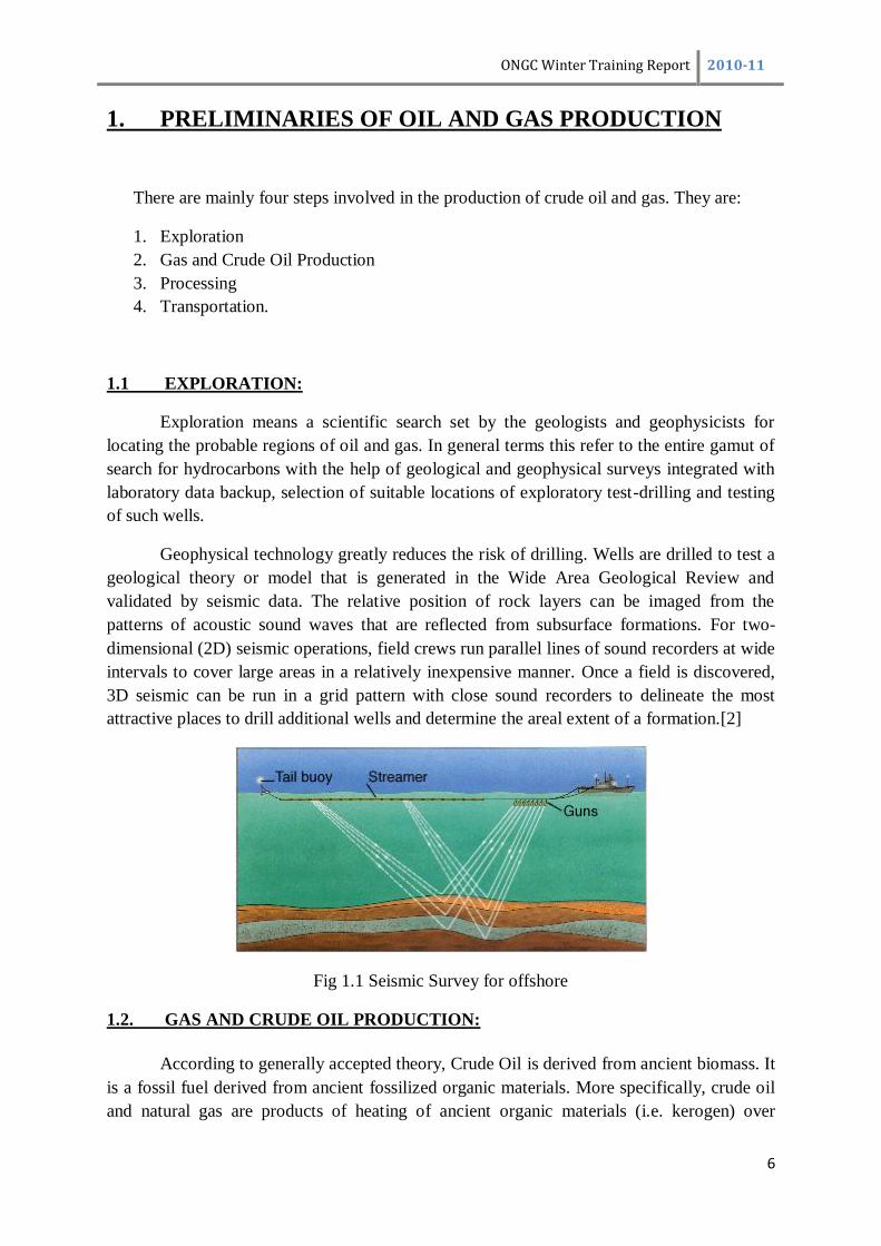
Geophysical technology greatly reduces the risk of drilling. Wells are drilled to test a
geological theory or model that is generated in the Wide Area Geological Review and
validated by seismic data. The relative position of rock layers can be imaged from the
patterns of acoustic sound waves that are reflected from subsurface formations. For two-
dimensional (2D) seismic operations, field crews run parallel lines of sound recorders at wide
intervals to cover large areas in a relatively inexpensive manner. Once a field is discovered,
3D seismic can be run in a grid pattern with close sound recorders to delineate the most
attractive places to drill additional wells and determine the areal extent of a formation.[2]
Fig 1.1 Seismic Survey for offshore
1.2. GAS AND CRUDE OIL PRODUCTION:
According to generally accepted theory, Crude Oil is derived from ancient biomass. It
is a fossil fuel derived from ancient fossilized organic materials. More specifically, crude oil
and natural gas are products of heating of ancient organic materials (i.e. kerogen) over

ONGC Winter Training Report 2010-11
7
geological time. Three conditions must be present for oil reservoirs to form: a source rock
rich in hydrocarbon material buried deep enough for subterranean heat to cook it into oil; a
porous and permeable reservoir rock for it to accumulate in; and a cap rock (seal) or other
mechanism that prevents it from escaping to the surface. Within these reservoirs, fluids will
typically organize themselves like a three-layer cake with a layer of water below the oil layer
and a layer of gas above it according to their densities, although the different layers vary in
size between reservoirs. Because most hydrocarbons are lighter than rock or water, they often
migrate upward through adjacent rock layers until either reaching the surface or becoming
trapped within porous rocks (known as reservoirs) by impermeable rocks above. However,
the process is influenced by underground water flows, causing oil to migrate hundreds of
kilometers horizontally or even short distances downward before becoming trapped in a
reservoir. When hydrocarbons are concentrated in a trap, an oil field forms, from which the
liquid can be extracted by drilling and pumping.[3]
Fig1.2: Hydrocarbon trapping in an anticline structure[4]
Prospects must be well defined in order to obtain oil and gas leases from landowners
prior to the drilling of a wildcat well after the necessary land work has been completed, the
drilling rig is moved on site and crews work 24 hours a day to drill a hole for the calculated
depth.
Once the hole has been drilled to the target formation, the well is logged with
electronic downhole measurement tools to record the characteristics of the subsurface rock
formations. If logging indicates the well is productive, it is cased with steel pipe and a
wellhead of shutoff valves is installed to prepare for production. The well is completed by
perforating holes in the casing at the depth of the producing formation. Once a successful test
well or series of wells has been drilled, the economic potential of the hydrocarbon discovery
must be determined. This step includes estimating how much oil and gas is present (reserves),
the probable selling price, the cost of continuing the exploration effort as well as the cost of
full field development, and the taxes, royalties, and other expenses associated with producing
the oil field. If the venture looks promising, the final step is taken—development of a newly
discovered field.[3]

ONGC Winter Training Report 2010-11
8
Fig1.3: Typical oil and gas Fig1.4: Overview of Oil and Gas Production [2]
Well Configuration [4]
1.3. PROCESSING:
Offshore productions consists of a number of operations that allow the safe and efficient
production of hydrocarbons from the flowing wells. The key operations that will be
conducted at the offshore platform include:
Produced Hydrocarbon Separation
Gas Processing
Oil and Gas Export
Well Testing
Produced Water Treatment and Injection
Utillities to support these processes
Fig1.5: Schematic Diagram of an Offshore Process Complex[4]

ONGC Winter Training Report 2010-11
9
The Pipelines and Risers facility uses Subsea production wells. The typical High Pressure
(HP) wellhead at the bottom right, with its Christmas tree and choke, is located on the sea
bottom. A production riser (offshore) or gathering line (onshore) brings the well flow into the
manifolds. As the reservoir is produced, wells may fall in pressure and become Low Pressure
(LP) wells. This line may include several check valves. The choke, master and wing valves
are relatively slow, therefore in case of production shutdown, pressure before the first closed
sectioning valve will rise to the maximum wellhead pressure before these valves can close.
The pipelines and risers are designed with this in mind. Short pipeline distances is not a
problem, but longer distances may cause multiphase well flow to separate and form severe
slugs, plugs of liquid with gas in between, travelling in the pipeline. Severe slugging may
upset the separation process, and also cause overpressure safety shutdowns. Slugging might
also occur in the well as described earlier. Slugging may be controlled manually by adjusting
the choke, or with automatic slug controls. Further, areas of heavy condensate might form in
the pipelines. At high pressure, these plugs may freeze at normal sea temperature, e.g. if
production is shut down or with long offsets. This may be prevented by injecting ethylene
glycol. Check valves allow each well to be routed into one or more of several Manifold
Lines. There will be at least one for each process train plus additional Manifolds for test and
balancing purposes. The Check valves systems have been not included in the diagram to
avoid complexity of the diagram. The well-stream may consist of Crude oil, Gas,
Condensates, water and various contaminants. The purpose of the separators is to split the
flow into deable fractions. The main separators are gravity type. As mentioned the production
choke reduces the pressure to the HP manifold and First stage separator to about 3-5 MPa
(30-50 times atmospheric pressure). Inlet temperature is often in the range of 100-150
degrees C. The pressure is often reduced in several stages, three stages are used, to allow
controlled separation of volatile components. The purpose is to achieve maximum liquid
recovery and stabilized oil and gas, and separate water. A large pressure reduction in a single
separator will cause flash vaporization leading to instabilities and safety hazards. An
important function is also to prevent gas blow-by which happens when low level causes gas
to exit via the oil output causing high pressure downstream. The liquid outlets from the
separator will be equipped with vortex breakers to reduce disturbance on the liquid table
inside. Emergency Valves (EV) are sectioning valves that will separate the process
components and blow-down valves that will allow excess hydrocarbons to be burned off in
the flare. These valves are operated if critical operating conditions are detected or on manual
command, by a dedicated Emergency Shutdown System There also needs to be enough
capacity to handle normal slugging from wells and risers. Other types of separators such as
vertical separators, cyclones (centrifugal separation) can be use to save weight, space or
improve separation There also has to be a certain minimum pressure difference between each
stage to allow satisfactory performance in the pressure and level control loops.The second
stage separator is quite similar to the first stage HP separator. In addition to output from the
first stage, it will also receive production from wells connected to the Low Pressure manifold.
The pressure is now around 1 MPa (10 atmospheres) and temperature below 100 degrees C.
The water content will be reduced to below 2%. An oil heater could be located between the
first and second stage separator to reheat the oil/water/gas mixture. This will make it easier to
separate out water when initial water cut is high and temperature is low. The heat exchanger

ONGC Winter Training Report 2010-11
10
is normally a tube/shell type where oil passes though tubes in a cooling medium placed inside
an outer shell. The third stage basically uses a Flash-Drum. Further reduction of water
percentage is done in the GDU (Gas Dehydration Unit). On an installation such as this,
when the water cut is high, there will be a huge amount of produced water. Water must be
cleaned before discharge to sea. Often this water contains sand particles bound to the
oil/water emulsion. The environmental regulations in most countries are quite strict, It also
places limits other forms of contaminants. This still means up to one barrel of oil per day for
the above production, but in this form, the microscopic oil drops are broken down fast by
natural bacteria. Various equipments are used, First sand is removed from the water by using
a sand cyclone. The water then goes to a hydrocyclone, a centrifugal separator that will
remove oil drops. The hydrocyclone creates a standing vortex where oil collects in the middle
and water is forced to the side. Finally the water is collected in the water de-gassing drum.
Dispersed gas will slowly rise to the surface and pull remaining oil droplets to the surface by
flotation. The surface oil film is drained, and the produced water can be discharged to sea.
Recovered oil in the water treatment system is typically recycled to the third stage separators.
The gas train consist of several stages, each taking gas from a suitable pressure level in the
production separator’s gas outlet, and from the previous stage. Incoming gas is first cooled in
a heat exchanger and goes into the compressors. For the compressor operate in an efficient
way, the temperature of the gas should be low. The lower the temperature is the less energy
will be used to compress the gas for a given final pressure and temperature. Temperature
exchangers of various forms are used to cool the gas, The separated gas may contain mist and
other liquid droplets. Liquid drops of water and hydrocarbons also form when the gas is
cooled in the heat exchanger, and must be removed before it reaches the compressor. If liquid
droplets enter the compressor they will erode the fast rotating blades for which gas is passed
through a scrubber and reboiler system to remove the remaining fraction of water from the
gas. When the gas is exported, many gas trains include additional equipment for further gas
processing, to remove unwanted components such as hydrogen sulphide and carbon dioxide.
These gases are called sour gas and sweetening /acid removal is the process of taking them
out.
1.4. TRANSPORTATION:
The gas pipeline is fed from the High Pressure compressors. Oil pipelines are driven
by separate booster pumps. For longer pipelines, intermediate compressor stations or pump
stations will be required due to distance or crossing of mountain ranges.
ONGC Winter Training Report 2010-11
11
2. OFFSHORE DESIGN SECTIONS
There are basically two divisions under engineering services – Offshore Design Section
(ODS) and Offshore Works Division (OWD). During the tenure of the training our focus was
mainly on ODS, under which there are seven disciplines-
1. Process
2. Piping
3. Pipelines
4. Instrumentation
5. Electrical
6. Mechanical
7. Structure
2.1 PROCESS
This discipline lays out the initial specifications required for the process platform in
the offshore. Any process platform is the gathering and distribution point for all the pipelines
i.e. well fluid lines, lift gas lines and oil export line for tanker loading. All the processing
facilities i.e. separation, produced water treatment, gas compression and dehydration, gas
sweetening is installed on this platform. In addition there are testing facilities for testing of
production coming from individual platforms.
Therefore, using many softwares like ASPEN HYSYS, SMARTPLANT etc. the
process discipline under ODS drafts out the basic plans for any offshore process platform.
The various diagrams like PFDs (Process Flow Diagram) and P&IDs (Piping and
instrumentation diagram) are being designed by the people of this discipline. After the
process design is completed the feasibility study for the designed process is carried out for
future bidding and finalisation for the design.
2.2 PIPING
The piping discipline under ODS looks after the pipes on the process platform. Plant
layout and design of piping systems constitutes a major part of the design and engineering
effort. Basically the following are the main tasks carried out by this discipline:
Piping and instrumentation diagrams (P&IDs)
Piping design and engineering principles
Terminology, symbols and abbreviations used in piping design
Piping materials
Piping specifications and piping codes
Components of piping systems - fittings, flanges and valves[5]

ONGC Winter Training Report 2010-11
12
The main base for all the calculations is Hoop Stress for all the stress calculations and
wall thickness. Wall thickness selection is one of the most important and fundamental tasks
in design of offshore pipelines. While this task involves many technical aspects related to
different design scenarios, primary design loads relevant to the containment of the internal
pressure
This discipline uses various software and standard codes for the design purposes.
Among the standard codes, ONGC follows the ASME B31 code for pressure piping of a
number of individually published sections. The codes used are B31.3 (Process Piping), B31.8
(Gas transportation and distribution piping system) and B31.4 (Pipeline transportation
systems for liquid hydrocarbons and other liquids)
2.3 PIPELINES
Pipelines are used for a number of purposes in the development of offshore hydrocarbon
resources These include e.g.:
Export (transportation) pipelines
Pipeline bundles.
Flow lines to transfer product from a platform to export lines
Water injection or chemical injection flow lines
Flowlines to transfer product between platforms, subsea manifolds and satellite wells
The design of pipelines is usually performed in three stages, namely;
Conceptual engineering,
Preliminary engineering or pre-engineering,
Detail engineering.[6]
Fig 2.1 The pipeline control for any offshore platform

ONGC Winter Training Report 2010-11
13
Fig 2.2 Flowline design process
Fig. Below shows the laying of the subsea pipeline, a number of pieces of pipes are welded
on the barge and the assembly is made to shift slowly, the assembly acts as a thread and lay
down on the seabed
Fig 2.3 Laying of Subsea pipeline on the seabed.

ONGC Winter Training Report 2010-11
14
2.4 INSTRUMENTATION
Instrumentation discipline comes into play after the process platform has been
designed by the process design section with the help of a P&ID. This discipline helps in
controlling and automating all the process parameters involved in the offshore as well as in
the onshore process platforms.
The various controlling instruments looked after by this discipline may be either
pneumatic or electronic. It deals with the measurement of pressure, temperature, flow-rates
with the help pressure transducers, temperature sensors (RTD, Thermocouples etc.) and flow
meters respectively. Instrumentation discipline also takes care of the ―Shut Down Panel‖
which shuts down all the processes in case of an emergency.
2.5 ELECTRICAL
Every power plant needs one or the other way electrical power for its proper
functioning. For an offshore platform it requires huge electrical power to run all the
mechanical devices employed, living quarters electrical consumption and also some power to
run various instruments.
For any general platform of ONGC, it requires about 20-25 MW or more power to run
the system. To produce such large amount of power is challenging. For this ONGC has its
own power production unit where power is generated by a portion of the natural gas
produced. There are huge Gas Turbine Units (GTU) for power production. Also the circuit
breaker station is installed on the platform itself. For some other purposes which may require
small power say few KWs, power is generated by the renewable sources of energy like solar
energy, wind energy etc.
2.6 MECHANICAL
The Mechanical devices such as Turbines, Compressors, Pumps, Heat Exchangers etc.
are the basics for a plant to operate and such devices are included under the Mechanical
discipline for both running and maintenance of the same. A small introduction about the main
mechanical units operating in a offshore process platform is given below
2.6.1 Gas Turbines
Gas Turbines are used for the power production by rotation of the turbine shaft by
steam generated due to heat generated by burning a portion of natural gas produced. An
efficient gas turbine used in a power plant produces about 10-15 MW of power under
optimized conditions. Special care is taken for the inlet gas entering into the turbine as wet
gas may corrode the blades of the turbine and also reduces the efficiency furthermore due to
corrosion it may cost economic loss to the plant.

ONGC Winter Training Report 2010-11
15
2.6.2 Gas Compressors
A gas compressor is a mechanical device that increases the pressure of a gas by
reducing its volume. Compressors are similar to pumps: both increase the pressure on a fluid
and both can transport the fluid through a pipe. As gases are compressible, the compressor
also reduces the volume of a gas. Liquids are relatively incompressible, while some can be
compressed, the main action of a pump is to pressurize and transport liquids. Normally a
three stage compression system is applied in a gas based power plant.[7]
Below are the different types of gas compressors:
The centrifugal types are mostly used in gas plants.
Fig 2.4 Multi Stage Compressor[8]
2.6.3 Heat Exchangers
Heat Exchangers exchanges heat between two fluids, In ONGC heat exchanger used
is the tube and shell type. Mainly these units are used during crude oil components separation
in which a portion of the crude oil is heated and passed through tubes and other portion is
passed through shell in this way exchange of heat takes place reducing the viscosity of the
fluid which is necessary to avoid vortex formation and maintain almost laminar flow within

ONGC Winter Training Report 2010-11
16
the pipes which helps in avoiding condensate formation. Also since compressors require the
temperature of the entering gas to be low for its efficient working temperature exchangers of
various forms are used to cool the gas.
2.6.4 Knock Out Drums (KOD)
The knock out drums is used for the separation of gas and oil from the saline water.
Mainly the principle involved is the gravity separation (baffle plates are present inside them)
in which the components are separated depending on their density.
2.6.5 Pumps
Pumps are basically used for transporting incompressible fluids like crude oil by
creating large pressure difference for its transportation along pipelines. Presently in ONGC
centrifugal type pumps are used for general purposes.
2.7 STRUCTURE
Structure discipline designs the supporting structure of the platform and the topside
considering the stress analysis criteria. They use many softwares like SACS, MicroStation
etc. for the design purposes.
2.7.1 Supporting Structures
The supporting structure on which the platform rests is divided into:
1. Jackets
2. FPSO(Floating production storage and offloading)
3. Jack up rigs
4. Semi Submersible Platform
5. Gravity based structures
6. Spar
2.7.1.1 Jackets
Jackets are broadly classified into 3/4/6/8 legged, depending upon the surface area of
the platform required. A jacket can be used only for smaller depth say 60-70 metres as the
jacket structure rests on the seabed, a typical four legged jacket is shown below. The jacket
supports a sub-frame with production equipment and accommodation deck on top of it. The
jacket has to be transported on a barge to its installation site at sea. While installing jacket on
the seabed steam hammering is done while piling them for stability. Sometimes skirt piles are
also given for providing support to the bigger jacket structure. The other processes which are
involved while installing the jacket are: cementing of legs of jacket, provision of the mud mat
at the base, battering of the legs (single batter on one side and double batter on the other side,
this is done in order to let the barge approach to the platform to install the drill rigs),
provision for the riser is also included in the design.

ONGC Winter Training Report 2010-11
17
.
Fig.2.5 A Four Legged Jacket[9]
2.7.1.2 FPSO
A Floating Production, Storage and Off-loading vessel (FPSO) is generally based on
the use of a tanker hull, which has been converted for the purpose. Such vessels have a large
storage capacity and deck area to accommodate the production equipment and
accommodation. When converting old tankers for this purpose, special attention has to be
paid to the fatigue life of the vessel.
Fig.2.6 FPSO[9]
2.7.1.3 Jack-Up Rigs
A jack-up is a mobile drilling unit that consists of a self-floating, flat box-type deck
structure supporting the drilling rig, drilling equipment and accommodation. It stands on 3 or
4 vertical legs along which the platform can be self-elevated out of the water to a sufficient
height to remain clear of the highest waves. Drilling operations take place in the elevated
condition with the platform standing on the sea bed. This type of platform is used for drilling
operations in water depths up to about 100 m. Jack-ups spend part of their life as floating
structures. This is when such platforms are towed to a new location by means of ocean-going
tugs. In this mode, the legs are lifted up and extend upwards over the platform.

ONGC Winter Training Report 2010-11
18
Fig.2.7 Jack-Up Rig
2.7.1.4 Semi-Submersible Platform
A Semi-Submersible Platform consists of a rectangular deck structure supported by
4to 8 surface-piercing vertical columns standing on submerged horizontal floaters. These
vessels have good motion characteristics and do not require the heading changed as the
predominant direction of the weather changes. The vessels are moored by means of 8 to 12
catenary mooring lines consisting of chains or combinations of chain and wire. Parts of the
pipelines transporting the oil to the floater have to be flexible to allow for the wave induced
motions of the floater. These flexible pipe lines have to be sufficiently strong and resilient to
withstand high pressures and temperatures of the crude oil as well as the continual flexing
due to the floater motions.
Fig. 2.8 A semi Submersible platform
2.7.1.5 Gravity Based Structures
Gravity Base Structures (GBS) are applied to remote fields in deep and harsh waters
in the central and northern part of the North Sea. They consist of a combination of a number
of large diameter towers, placed on top of a large area base which contains also storage
capacity. Piling to the sea bed is not required because of the large size of the base and the

ONGC Winter Training Report 2010-11
19
mass of the structure, but the sea bed has to be levelled. The towers support a sub-frame with
a production equipment and accommodation deck on top of it.
Fig 2.9. A GBS
2.7.1.6 Spar
Spar is basically a mono legged platform of smaller surface area and is mostly
employed for larger depths of more than 1 km. All the basic facilities are provided on the
platform for the various production purposes.
Fig 2.10 A Spar
2.7.1.7 Tension Leg Platform
A Tension Leg Platform (TLP) consists of a semi-submersible type hull with for
instance four vertical surface-piercing columns standing on underwater floaters and
supporting a large rectangular deck. At each of the four corners of the floater, pre tensioned
tethers extend vertically downwards to foundation templates which are piled into the sea bed.
Due to the vertical tendons, which are pre-tensioned to such a degree that they never become
slack, any vertical motion of the TLP will be eliminated. This allows for steel pipe line
ONGC Winter Training Report 2010-11
20
connections between the wells and the floater, without the need for flexible sections of pipe
lines.[9]
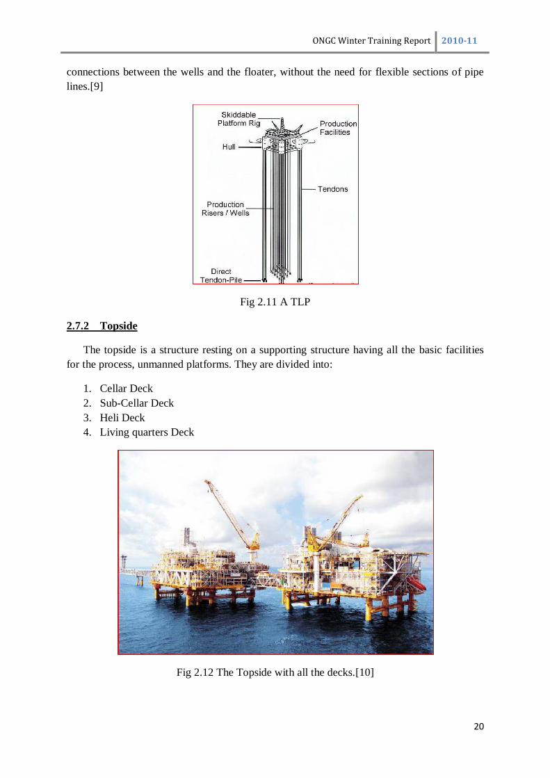
Fig 2.11 A TLP
2.7.2 Topside
The topside is a structure resting on a supporting structure having all the basic facilities
for the process, unmanned platforms. They are divided into:
1. Cellar Deck
2. Sub-Cellar Deck
3. Heli Deck
4. Living quarters Deck
Fig 2.12 The Topside with all the decks.[10]
ONGC Winter Training Report 2010-11
21
3. DRILLING PROCESSES
A major difference between onshore and offshore drilling is the nature of the drilling
platform. In addition, in offshore drilling the drill pipe must pass through the water column
before entering the lake or seafloor. Offshore wells have been drilled in waters as deep as
10,000 ft (305 m).
The following text provides an overview of drilling in offshore environments:
3.1 DRILLING TEMPLATES
Offshore drilling requires the construction of an artificial drilling platform, the form
of which depends on the characteristics of the well to be drilled. Offshore drilling also
involves the use of a drilling template that helps to connect the underwater drilling site to the
drilling platform located at the water’s surface. This template typically consists of an open
steel box with multiple holes, depending on the number of wells to be drilled. The template is
installed in the floor of the water body by first excavating a shallow hole and then cementing
the template into the hole. The template provides a stable guide for accurate drilling while
allowing for movement in the overhead platform due to wave and wind action.
3.2 DRILLING PLATFORMS
There are two types of basic offshore drilling platforms, the movable drilling rig and
the permanent drilling rig. The former is typically used for exploration purposes, while the
latter is used for the extraction and production of oil and/or gas. A variety of movable rigs are
used for offshore drilling. Drilling barges are used in shallow (<20 ft [<6 m] water depth),
quiet waters such as lakes, wetlands, and large rivers. As implied by the name, drilling barges
consist of a floating barge that must be towed from location to location, with the working
platform floating on the water surface. In very shallow waters, these may be sunk to rest on
the bottom. They are not suitable for locations with strong currents or winds and strong wave
action. Like barges, jack-up rigs are also towed, but once on location three or four legs are
extended to the lake bottom while the working platform is raised above the water surface;
thus, they are much less affected by wind and water current than drilling barges.
3.3 DRILLING TECHNIQUES
Several types of drilling techniques are currently employed in oil and gas drilling:
straight hole drilling, directional drilling, horizontal drilling, air drilling, and foam drilling.
Regardless of the drilling technique, a well is typically drilled in a series of progressively
smaller-diameter intervals.

ONGC Winter Training Report 2010-11
22
3.3.1 Straight Hole Drilling
In straight hole drilling, the well bore is vertical and deviates by no more than 3
degrees anywhere along the well bore, and the bottom of the well deviates by no more than 5
degrees from the starting point of the well bore at the drilling platform. With straight hole
drilling, the drill bit may be deflected if it contacts fault zones or dipping beds of hard rock
layers.
3.3.2 Directional and Horizontal Drilling
Directional drilling (also termed slant drilling) involves the drilling of a curved well
to reach a target formation. Directional drilling is employed when it is not possible,
practicable, or environmentally sounds to place the drilling rig directly over the target area.
Directional drilling is especially useful for offshore locations. With directional drilling, it
may take several thousand feet for the well to bend from drilling vertically to horizontally.
Fig 3.1 Directional and Horizontal drilling
3.4 WELL COMPLETION
Once a well has been drilled and verified to be commercially viable, it must be
completed to allow for the flow of oil or gas. The completion process involves the
strengthening of the well walls with casing and installing the appropriate equipment to
control the flow of oil or gas from the well. Casing consists of a stacked series of metal pipes
installed into the new well in order to strengthen the walls of the well hole, to prevent fluids
and gases from seeping out of the well as it is brought to the surface, and to prevent other
fluids or gases from entering the rock formations through which the well was drilled.[11]

ONGC Winter Training Report 2010-11
23
4. URAN VISIT
4.1 INTRODUCTION :
Crude oil and associated gas produced at Bombay High fields and satellite fields are
transported to URAN onshore facilities through sub-sea pipelines for further processing. Oil
& Gas is brought from Bombay High fields through 204 km long 40" dia. & 26" dia. trunk
lines respectively and from satellite fields through 81 km long 2" dia. & 26" dia. trunk lines
respectively.
4.2 OIL & GAS PROCESSING FACILITIES:
The crude oil received from offshore is stabilised in crude stabilisation unit (CSU)
through three stage separation with a view to optimise the liquid recovery. The liberated gas
from CSU is compressed and mixed with offshore gas and fed to gas processing unit. The
stabilised oil is stored in floating roof tanks and as per demand of refineries is sent to
Trombay Terminal for onward transportation to refineries situated at Trombay and to various
coastal refineries through Jawahar Deep tanker loading terminal.
Fig4.1: Overall Schematic of Uran Complex
Associated gas is received at slug catcher, where condensate formed during travel
time gets separated. Gas from slug catcher along with CSU offgas and Condensate
Fractionating Unit (CFU) offgas is routed to Gas Sweetening Unit (GSU) which consists of
two trains viz. GSU-I & GSU-II with handling capacity of 5.75 MMSM4 per day of each
train. The remaining gas is directly sent to consumers along with lean gas coming from the
processing plants. After removal of CO2 & H2S at GSU, treated gas is routed to LPG recovery
CRUDE OIL TO STORAGE
OFFSHORE
GAS
CRUDE OIL
FROM
OFFSHORE PRODUCED WATER
TO ETP
LPG TO STORAGE
NAPHTHA TO STORAGE
C2C3 TO
STORAGE
SSV
LEF
GAS TO CONSUMER
ACID GAS
SLUG
CATCHER
GAS
SWEETENING
UNIT C2C3
PLANT
CONDENSATE FRACTIONATING
UNIT
CRUDE
STABILISATION
UNIT
CSU OFFGAS
COMPRESSOR
LPG
PLANT
ONGC Winter Training Report 2010-11
24
plant, which consists of two Units viz. LPG-I & LPG-II for extraction of LPG &
NGL/Naphtha. Remaining Second stage vapours (SSV) & Light End Fractionating column
(LEF) overhead vapour is taken to Ethane Propane Recovery Unit (EPRU) for recovery of
Ethane-Propane. The lean gas after recovery of Ethane-Propane is supplied to M/s. GAIL for
onward supply to various gas consumers like USAR LPG Plant, RCF, MSEB,
TEC,BPCL/HPCL, DFPCL etc. Ethane-Propane (liquefied) is sent to MGCC, Nagothane for
using as feed stock to Gas Cracker Unit. LPG & NGL/Naphtha are supplied to BPCL &
HPCL refineries. Naphtha is also supplied to various on land consumers or exported.
Condensate separated at slug catcher and at CSU off-gas compressors is sent to CFU-II for
removal of light end hydrocarbon gases and for recovery of LPG & NGL/Naphtha. The
treated condensate can also be routed to LPG plant for recovery of LPG & NGL/Naphtha.
There are various interconnection and safety features in the plants for ensuring greater
flexibility and safe operation of each plant.
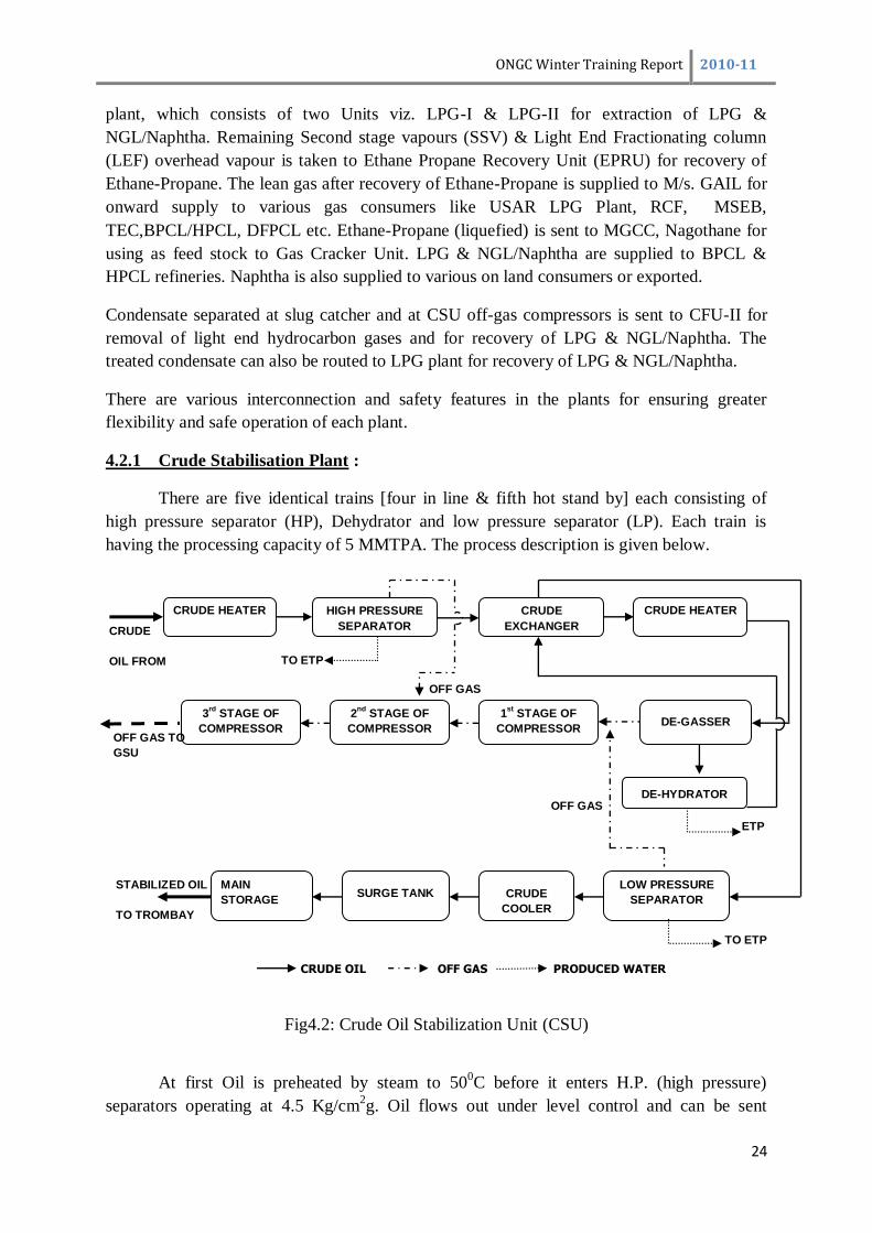
4.2.1 Crude Stabilisation Plant :
There are five identical trains [four in line & fifth hot stand by] each consisting of
high pressure separator (HP), Dehydrator and low pressure separator (LP). Each train is
having the processing capacity of 5 MMTPA. The process description is given below.
Fig4.2: Crude Oil Stabilization Unit (CSU)
At first Oil is preheated by steam to 500C before it enters H.P. (high pressure)
separators operating at 4.5 Kg/cm2g. Oil flows out under level control and can be sent
OFF GAS
CRUDE HEATER
HEATER
3rd
STAGE OF
COMPRESSOR
CRUDE
OIL FROM
OFFSHORE
HIGH PRESSURE
SEPARATOR
SEPARATOR
CRUDE
EXCHANGER
EXCHANGER
CRUDE HEATER
HEATER
2nd
STAGE OF
COMPRESSOR
1st
STAGE OF
COMPRESSOR DE-GASSER
MAIN
STORAGE SURGE TANK
TANK
CRUDE
COOLER
COOLER
LOW PRESSURE
SEPARATOR
DE-HYDRATOR
OFF GAS TO
GSU
STABILIZED OIL
TO TROMBAY
TO ETP
OFF GAS
ETP
TO ETP
CRUDE OIL OFF GAS PRODUCED WATER

ONGC Winter Training Report 2010-11
25
directly to low pressure separators or can be pumped to the Dehydrator system. Gas liberated
from H.P. separator under pressure control is sent to second stage of compressor system for
compression. Oil containing water and salt, can be dehydrated in the Dehydrator systems. A
high voltage electric field (normally 16,000 volt) is applied inside the dehydrator for effective
separation of water from oil. Gas liberated from the dehydrator flows under pressure control
to the first stage of the compressor. The produced water flows through interface level control
valve and is sent to the Effluent Treatment Plant for further treatment. The dehydrators are
also capable of desalting for which fresh water injection and mixing valve facility are
provided upstream of Dehydrator. Oil from the low pressure separators after getting cooled to
40C in the water cooler, flows to the Surge Tanks. Gas liberated from L.P. separator is sent to
first stage of compressor system along with gas coming out from dehydrators for
compression. The stabilised oil is pumped to the main storage tanks (8 Nos. x 60000 M4). Oil
is pumped to Trombay Terminal for onward distribution to BPCL, HPCL storage and other
coastal refineries via Jawahar Dweep jetty. Gases from HP separators, Degassers and LP
separators are compressed in the associated gas compressors and mixed with offshore gas
before feeding to GSU.
4.2.2 Condensate Fractionating Unit (CFU - I) :
The condensate fractionation unit will remove CO2, H2S and lighter hydrocarbons
from the condensate. The condensate from Slug Catcher unit is sent to a Stripper Feed
Coalescer. The free water collected in the bottom is removed through interphase level
controller. Condensate from the Coalescer is taken to Stripper Column through a back
pressure control valve. GSU Knock-out Drum condensate is also fed to Stripper Column. The
compressor discharge is sent to Gas sweetening Unit. Stripper Bottom Product is sent to LPG
plants. Alternatively, bottom product from stripper column can also be sent to LPG column of
CFU-II.
4.2.4 Condensate Fractionating Unit (CFU - II) :
The condensate fractionating unit-II will remove CO2, H2S and lighter hydrocarbons
from sour condensate and will produce LPG & NGL/Naphtha.
Condensate is received from slug catcher alongwith condensate of CSU off gas compressors
in condensate surge drum. The free water is collected in the bottom and removed through
interphase level controller. After this, the condensate is passed through Coalescer to remove
water content of the condensate. The column top gas leaves at and compressed in one of the
two off gas compressors. The top vapours are cooled and collected in a vessel as LPG. Part of
the liquid is refluxed to maintain the purity and remaining liquid is pumped to LPG sphere.
The bottom liquid is pumped to storage as NGL/Naphtha.
4.2. Gas Sweetening Unit ( GSU ) :
There are two trains in GSU for sweetening of sour gas with design capacity of each
train 5.75 MMSM4/Day of mixed sour gas feed. Process used is Shell's proprietary
sulfinol - D process. Process description is as given below.
ONGC Winter Training Report 2010-11
26
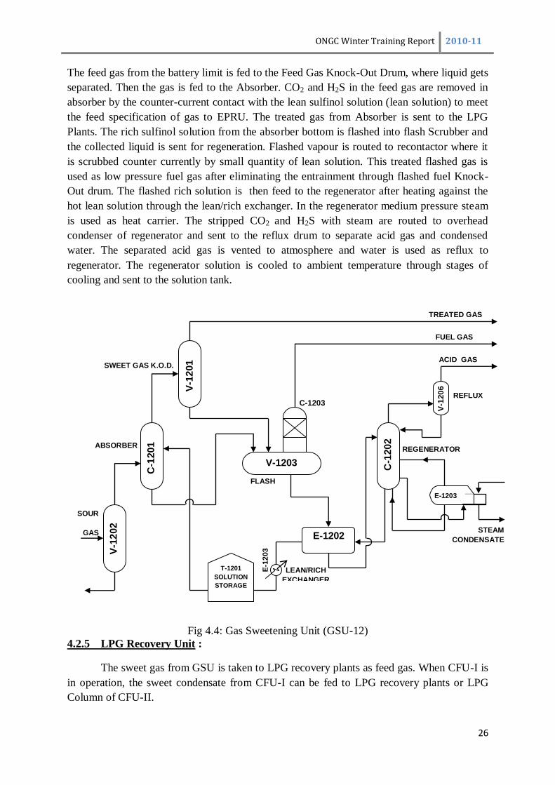
The feed gas from the battery limit is fed to the Feed Gas Knock-Out Drum, where liquid gets
separated. Then the gas is fed to the Absorber. CO2 and H2S in the feed gas are removed in
absorber by the counter-current contact with the lean sulfinol solution (lean solution) to meet
the feed specification of gas to EPRU. The treated gas from Absorber is sent to the LPG
Plants. The rich sulfinol solution from the absorber bottom is flashed into flash Scrubber and
the collected liquid is sent for regeneration. Flashed vapour is routed to recontactor where it
is scrubbed counter currently by small quantity of lean solution. This treated flashed gas is
used as low pressure fuel gas after eliminating the entrainment through flashed fuel Knock-
Out drum. The flashed rich solution is then feed to the regenerator after heating against the
hot lean solution through the lean/rich exchanger. In the regenerator medium pressure steam
is used as heat carrier. The stripped CO2 and H2S with steam are routed to overhead
condenser of regenerator and sent to the reflux drum to separate acid gas and condensed
water. The separated acid gas is vented to atmosphere and water is used as reflux to
regenerator. The regenerator solution is cooled to ambient temperature through stages of
cooling and sent to the solution tank.
Fig 4.4: Gas Sweetening Unit (GSU-12)
4.2.5 LPG Recovery Unit :
The sweet gas from GSU is taken to LPG recovery plants as feed gas. When CFU-I is
in operation, the sweet condensate from CFU-I can be fed to LPG recovery plants or LPG
Column of CFU-II.
SWEET GAS K.O.D.
FLASH
SCRUBBER
V-1203
E-1202
T-1201
SOLUTION
STORAGE
V-1
201
C-1
201
V-1
202
C-1
202
E-1203
A/B
ABSORBER
SOUR
GAS
K.O.D.
E-1
203
LEAN/RICH
EXCHANGER
FUEL GAS
ACID GAS
REFLUX
DRUM
C-1203
RE-CONTACTOR
REGENERATOR
STEAM
CONDENSATE
V-1
20
6
TREATED GAS

ONGC Winter Training Report 2010-11
27
Fig4.: Schematic of LPG Plant Basic process description is as given below:
4.2.5.1 Feed Gas drying:
Feed gas is dried in dryers to reduce moisture content to less than 5 PPM. Molecular
sieve is used as desiccant. Drying follows filtration of dust particles generated from
the Molecular sieves.
4.2.5.2 Chill down train :
Dry feed gas is progressively cooled in chill down train using process cold streams
and external propane refrigeration. After cold recovery Second Stage Separator
Vapour (SSV) is sent to EPRU for recovery of Ethane-Propane or sent to various
consumers.
4.2.5.4 Light End Fractionator (LEF) & residue gas compressor :
It removes all methane, ethane & a part of propane. Bottom stream containing a part
of propane (enough to make LPG), Butane and heavier hydrocarbons is feed to LPG
column. LEF overhead vapour is taken to EPRU for further recovery of Ethane-
Propane in EPRU Plant.
4.2.5. LPG Column :
Light end fractionator’s bottom stream flows to LPG column on its own pressure.
This column operates at 10 Kg/Cm2 top-pressure and about 15 º C bottoms and 60ºC
top temperatures. It separates out heavy ends from LPG. LPG is taken as top product
and the bottom product is sent to storage as NGL/Naphtha.
NGL/Naphtha
DRYERS FILTERS
SSV TO EPRU
LEF O/H TO EPRU
LPG PRODUCT
CONDENSATE
FROM CFU-I
REFRIGERATION
UNIT
SEPARATORS FRACTIONATING
COLUMNS

ONGC Winter Training Report 2010-11
28
4.2.6 Ethane-Propane Recovery Unit (EPRU) :
Fig 4.5 Schematic of EPRU
The Ethane-Propane Recovery Unit can be divided into the following subsections:-
Feed Gas Compression
Feed Gas Chilling & Separation
Feed Gas Expansion
Demethanizer
Lean Gas Recompression
Propane Refrigeration
4.2.6.1 Feed Gas Compression :
The second stage vapour from LPG-I & LPG-II is taken as feed gas to C2C4 plant.
The LEF overload vapour from LPG-I & II is also diverted to EPRU as separate feed
stock. The feed gas is taken to feed gas compressor suction knock-out drum. The gas
from knock-out drum is taken to the compressor of Demethanizer overhead expander
compressor. The compressed gas is directly taken to the suction of the compressor of
the feed gas expander compressor. Then compressed gas at 52.5 kg/cm2g is cooled to
0ºC & taken to chill down section for further chilling.
C2C3
PRE COMPRESSION OF FEED
THROUGH EXPANDER DRIVEN
COMPRESSORS
1st
STAGE
CHILL DOWN
1st
STAGE
VAPOURS TO
2nd
STAGE
CHILL DOWN
2nd
STAGE
VAPOURS
LIQUID
SEPARATION
2nd
STAGE
VAPOURS
LIQUID
SEPARATION
CHILL DOWN
BY PROPANE
REFRIGERATION
FEED TO
DEMETHANISER
COLUMN
DE
ME
TH
AN
ISE
R
CO
LU
MN
LEAN GAS
SSV
FEED
LEF O/H
VAPOURS
1st
STAGE VAPOUR
LIQUID SEPARATION

ONGC Winter Training Report 2010-11
29
4.2.6.2 Feed Gas Chilling & Separation :
Feed gas after compression is cooled through heat exchangers from 0ºC to about
20ºC. Further feed gas is taken to Demethanizer bottom reboiler where it cooled down
to 2.5ºC. Then feed gas is taken to Chiller-I & Chiller-II for further chilling where it
receives cold by propane refrigeration & chilled down from 2.5ºC to -17ºC to -27ºC to
-55ºC. Then it is fed to separator-I to separate out condensate. The vapour from
separator-I is taken to Chiller-III where it is chilled further to -67ºC by exchange of
heat without going cold lean gas. The partially condensed feed gas at -67ºC is taken
to separator-II to separate out the condensate. The condensate from Separator-I &
Separator-II is directly fed to Demethanizer column at tray No.16. The vapour from
Separator-II at -67ºC is taken to feed gas expander for expansion.
The LEF vapour received as feed to EPRU is available at 45ºC is taken to LEF
vapour/lean gas exchanger where it is cooled down to 5ºC. Then it is further chilled
down to -7ºC & -20ºC at Chiller-I & Chiller-II respectively by use of propane
refrigeration. Then it is taken to Demethanizer side reboiler & chilled down to about -
44ºC. Further it is taken to Chiller-III & chilled down to -47ºC & directly taken to
Demethanizer column as feed at tray No.27.
3.2.6.3 Feed Gas Expansion :
Feed gas, after 2nd
stage separation at -67ºC from separator-II is taken to feed gas
expander compressor for expansion. The majority of the refrigeration need is made
available from this entropic expansion of gas from about 9.6 kg/cm2(g) to about 19.5
kg/cm2(g), the gas is further chilled down to about -100ºC and is partially condensed,
mechanical energy generated due to expansion is utilised to drive the compressor used
for compression of feed gas. The expander outlet partially condensed gas at -100ºC is
taken directly to Demethanizer column at tray No.10 for fractionation.
3.2.6.4 Demethanizer :
The Demethanizer column is provided to recover C2C4 product from the condensed
liquids at various stages in chill-down and expansion sections and remove all
undeable methane from it. Feed to the column is taken as follows:-
Feed gas expander outlet (vapour liquid) at tray No.10 at about -
100ºC
Mixture of separator-I & separator-II liquid at tray No.16 at about -
67ºC.
Partially condensate LEF vapour at tray No.25 or tray no.27 at about -
47ºC.
Of-spec C2C4 product, if any, from storage at tray No.0.
The vapour from Demethanizer reflux drum is taken to Demethanizer overhead
expander compressor, where it is expanded to about 1.5 Kg/cm2g. Due to this
expansion, gas is further chilled down to about -111ºC. This cold methane rich vapour
is utilised for refrigeration then it is taken to lean gas compressor.

ONGC Winter Training Report 2010-11
30
4.2.6.5 Lean Gas Compression:
The lean gas, after recovery of Ethane-Propane is received in lean gas compressor
knock-out drum at about 20ºC & 12.7 kg/cm2(g). Then lean gas is compressed to
about 0 kg/cm2
(g) by lean gas compressor. The compressed gas after cooling to about
0ºC is supplied at battery limit for gas consumers.
3.2.6.6 Propane Refrigeration System :
Propane refrigeration system has been provided to supplement refrigeration
requirement in EPRU. The feed gas is chilled down upto -67ºC with the help of
propane refrigeration system followed by further heat exchange.
4.2.7 Flare System:
In case of process upset gas is flared through two numbers of elevated flares for
lighter hydrocarbon and one box flare for heavier hydrocarbon, which are kept alive with the
help of purge gas for safety. If needed, low temperature liquids are diverted to blow down
drums, where it is converted into gas with the help of low-pressure steam and then diverted to
the flare header. Condensate formed, if any, is collected in flare knockout drum and pumped
back to process unit.
4.2.8 Effluent Treatment Plant:
Effluent received from CSU is routed to EPTP, where oil & water are separated using
gravity separation. Oil is sent back to CSU & water is further routed to surge pond where it
gets mixed with the effluents of other plants like LPG, GSU, and EPRU. This effluent is sent
to ETP (MINAS) Plant for further treatment before final discharge to sea through close
conduit disposal system. The process description of ETP (MINAS) having the capacity of
450 M3/Hr (dry weather) and 700 M
3/Hr (wet weather) is as given below.
Pre-treatment by gravity separation using corrugated plate interceptors (CPI) to
reduce gross separable oil contamination.
Primary treatment by sand filtration with in line polyelectrolyte addition to remove
suspended solids and flocculated oil.
Secondary treatment using biological filtration with random packed plastic media as
the substrate for the biomass. Di-ammonium phosphate addition in upstream of
Biotowers. Secondary treatment is meant for removing soluble pollutants (BOD).
Tertiary Treatment is provided in the form of conventional gravity clarifications to
remove any humus sludge from the Biotower effluent.
Polishing of treated effluent by means of sub surface aerators in the guard pond.
Disposal by pumping through closed conduit disposal system to low tide level into the
sea.

ONGC Winter Training Report 2010-11
31
Fig 4.6 Schematic of Effluent Treatment Plant
4.2.9 Propane Recovery Unit:
Propane is produced from LPG in LPG-I plant. Propane column (10-C-104) takes
LPG feed from the discharge of LPG reflux pump of LPG-I plant / LPG-II plant. The column
operates at about 15 Kg/Cm2 top-pressures and about 85 º C bottoms and 0ºC top
temperatures. Its top product is Propane and bottom which is butane goes to LPG spheres.
This is a small column and intended to meet the internal requirement of propane,
which is used as refrigerant in LPG and C2C4 plants.
Fig4.7 Schematic of Propane Recovery Unit
POLY ELECTROLYTE
DOSING UNIT
EFFLUENT FROM
OTHER SOURCES
EFFLUENT FROM
TANK FARM
EFFLUENT
FROM CSU
EFFLUENT PRE-
TREATMENT
PLANT
PLANT (EPTP)
SURGE
POND
CPI
SEPARATOR
DISCHARG
E TO SEA
THROUGH
CLOSED
CONDUIT
DISPOSAL
SAND
FILTERS
BIO TOWER-I CLARIFIER-I
BIO TOWER-II
GUARD
POUND
DISPOSAL
PUMP CLARIFIER-
II
RECYCLE
PUMPS
PROPANE TO STORAGE
PROPANE
COLUMN
FUEL GAS
TO LPG STORAGE
LPG

ONGC Winter Training Report 2010-11
32
5. SIMULATION OF PGC USING ASPEN HYSYS 7.1
5.1 INTRODUCTION:
ASPEN HYSYS 7.1 is a modern software meant for simulation and design of process
techniques involved in various engineering fields.
Basically we have used the software for the modeling and simulation of a typical
Process Gas Compressor Unit (PGC) in which three stage compression is done for higher
efficiency purpose, i.e. Compressors consuming less power. Mainly the type of compressor
used in the industry is the centrifugal type which is generally opted for handling higher mass-
flow rates but lower compression ratio is achieved, While a reciprocating type can be used
where necessarily higher compression ratio is deed.
5.2 DESCRIPTION:
Initially Sweet Gas is received from the Acid-Gas Recovery Unit (AGRU) and fed to
a mixer, another inlet to the mixer is meant for the molecular adjustment supplying methane
for controlling the molecular weight of the mixture whose composition is shown below:
Platform B23-A
Components Vol(%)
Methane 79.96
Ethane 5.10
Propane 2.02
i-Butane 0.34
n-Butane 0.54
i-Pentane 0.15
n-Pentane 0.20
Hexane 0.25
Heptane 0.15
CO2 9.37
Nitrogen 1.92
In general increasing the molecular weight decreases the power input to the
compressors but there is a limitation to the increase of molecular weight as it also increases
the mass flow rate and a particular compressor is designed for handling a defined mass flow,
also there is a third inlet to the mixer for the recycled gas and oil mix. In our case, the
molecular weight is 20 gm/mol taken according to the standard specification sheets by
SIEMEN’S. From the mixer, the Crude oil and gas mixture containing water is passed into a
Knock Out Drum (KOD-1) which separates gas from oil and water mix. Basically it uses the
gravity separation technique (having baffles) in which the gas being lighter passes from the
top and the oil water mix passes from the bottom to the disposal unit. The gas from the top
which is initially at 5 kg/cm2_g and 50 0C is passed into the compressor unit (comp.-1) which
compresses the gas to a pressure of about 15 kg/cm2_g (comp. ratio 3) and 134.6 oC
(calculations are based on Panng-Robinson’s equation) the first stage compression consumes
ONGC Winter Training Report 2010-11
33
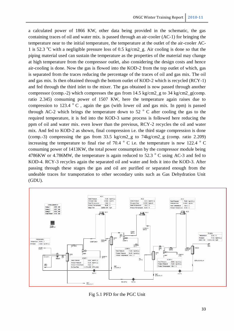
a calculated power of 1866 KW, other data being provided in the schematic, the gas
containing traces of oil and water mix. is passed through an air-cooler (AC-1) for bringing the
temperature near to the initial temperature, the temperature at the outlet of the air-cooler AC-
1 is 52.3 oC with a negligible pressure loss of 0.5 kg/cm2_g. Air cooling is done so that the
piping material used can sustain the temperature as the properties of the material may change
at high temperature from the compressor outlet, also considering the design costs and hence
air-cooling is done. Now the gas is flowed into the KOD-2 from the top outlet of which, gas
is separated from the traces reducing the percentage of the traces of oil and gas mix. The oil
and gas mix. Is then obtained through the bottom outlet of KOD-2 which is recycled (RCY-1)
and fed through the third inlet to the mixer. The gas obtained is now passed through another
compressor (comp.-2) which compresses the gas from 14.5 kg/cm2_g to 34 kg/cm2_g(comp.
ratio 2.345) consuming power of 1507 KW, here the temperature again raises due to
compression to 123.4 o
C , again the gas (with lower oil and gas mix. In ppm) is passed
through AC-2 which brings the temperature down to 52 o C after cooling the gas to the
required temperature, it is fed into the KOD-3 same process is followed here reducing the
ppm of oil and water mix. even lower than the previous, RCY-2 recycles the oil and water
mix. And fed to KOD-2 as shown, final compression i.e. the third stage compression is done
(comp.-3) compressing the gas from 33.5 kg/cm2_g to 74kg/cm2_g (comp. ratio 2.209)
increasing the temperature to final rise of 70.4 o C i.e. the temperature is now 122.4
o C
consuming power of 1413KW, the total power consumption by the compressor module being
4786KW or 4.786MW, the temperature is again reduced to 52.3 o C using AC-3 and fed to
KOD-4. RCY-3 recycles again the separated oil and water and feds it into the KOD-3. After
passing through these stages the gas and oil are purified or separated enough from the
undeable traces for transportation to other secondary units such as Gas Dehydration Unit
(GDU).
Fig 5.1 PFD for the PGC Unit

ONGC Winter Training Report 2010-11
34
6. CONCLUSION
Engineering services plays a vital role in the off shore design. It imparts extensive
support in the designing and processing of various off shore production taking place in the
sea. It looks after a number of various departments and hence its importance can be compared
to none when the question of implementing and executing the process comes.
Oil and gas industry thus has a huge role to play not only in the generation of power
but as well as blossoming India’s economy. They are the major contributors in Indian
economy and hence continuous efforts are being made for their exploration in the near future.
Finally, summing it up we consider ourselves fortunate to be a part of India’s tycoon
company for Oil &Gas Production, though for a short tenure only. We had a great exposure
to the oil and gas industry during our training as it continuously facilitated us developing our
knowledge to the where-about of oil and gas industry.

ONGC Winter Training Report 2010-11
35
7. REFERENCES
[1] IOGPT ONGC, 2009, ONGC Composite Catalogue.
[2]Tamareck, Oct 2002, “CONVENTIONAL OIL AND GAS, GEOPHYSICAL
EXPLORATION‖
[3]Excerpts for Rock talk, Vol 7 No.2 Colorado Geological Survey.
[4] ONGC, ―Glimpses of Production and process engg.ppt‖
[5]2009, Fundamentals of process plant piping and design.
[6] ELSEVIER OCEAN ENGINEERING BOOK SERIES VOLUME 3, ―Pipelines and
Risers‖
[7]A document on the internet – ―Wikipedia.org/gas_compressors‖
[8]A document on the internet - “Introduction to Centrifugal Compressors and Knock Out
Drums‖
[9]Journée J.M.J.,Massie W.W., Delft University of Technology First Edition, ―OFFSHORE
HYDROMECHANICS‖
[10]A document on the internet - Hyundai Heavy Industries Co. Ltd., Offshore &
Engineering
[11]November, 2005, ― OIL AND GAS EXPLORATION AND DRILLING
TECHNOLOGY‖