ontario association of foundation …oafs.org/downloads/safetyprocedures.pdf · rescue of a worker...
TRANSCRIPT

OAFS – Revised JUNE 2016
ONTARIO ASSOCIATION OF FOUNDATION SPECIALISTS
Guidelines for the Development of Safety Programs
Based on
Industry Standards, Regulations
and Best Practices in Ontario, Canada
JUNE - 2016

OAFS – Revised JUNE 2016
TABLE OF CONTENTS Introduction Page 1 Location of Underground Utilities Page 1-2
Rotary Foundation Drill Rigs
Regulatory Requirements in Ontario Page 2
Supporting Surface / Working Platform Page 2-3
Operator Training Requirements Page 3
Drilling Operations
General Page 3-5
Ground Procedures during Drilling Operations Page 5-6
Caisson Access and Egress Page 7-10
Rescue of a Worker from a Caisson Page 10
Soil Classifications and Excavations Page 11-12
Drilling Procedures to Prevent Caving or Loss of Ground Page 11-12
Crane & Hoisting Operations
General Page 13-16
Pile Driving Operations
Procedure for Driving Piles Page 16-17
Driving Lead Climbing Procedure Page 17-18
Lead Climbing Rescue Procedure Page 18-19
Vibratory Hammers Page 20
Appendix A Warning Barriers & Physical Barricades Page 21
Appendix B Fixed Supports Page 22
Appendix C Hole Covers Page 23
Appendix D Crane & Pile Driving Signals
Hand Signals for Hoisting Operations Page 24-25
Pile Driving Signals Page 26

OAFS – Revised JUNE 2016 Page 1
Introduction:
This document is intended to serve as a guideline to assist employers in developing health and safety programs for the drilled and driven foundation industry. This guideline has been developed by the Ontario Association of Foundation Specialists Safety Committee through a review of industry standards, regulations and best practices.
Locating Underground Utilities
1. The foundation contractor must be aware of all services that may affect the work or that maybe located in the work zone and have a valid copy of all locates.
2. Locates shall be obtained prior to commencement of drilling by contacting OOC (Ontario One Call) @ 1-800-400-2255 and additionally any utility owner that is not associated with OOC. Locates are only valid for a total of 30 days from the date of issue. Mechanical equipment must not be used to excavate within 1.0 m of each side of the centre line of the marked utilities. Always refer to the special instructions section of the utility locates for further instruction from the utility owner
3. Proof that locates were completed are required on site for the duration of the project.
4. Clearly marked stakes, flags or paint will indicate the location of various underground utilities.
5. In the case of any uncertainty as to specific location of underground utilities, excavation, drilling or driving of piles is not to commence until the service is exposed or located by hand (shoveling) or other means (e.g. hydrovac).
6. The underground utility must be located by hand excavation and visually inspected if located close to the work area. If the located utility stakes or paint is within a distance equal to the stake-out tolerance (typically 1m) then hand-excavated test pits shall be required prior to commencement of foundation work.
7. Services that are known to be close to the foundation elements may require some type of special protection. Contact the appropriate utility owner to agree on such protective measures.
8. If unanticipated underground utilities are encountered, work shall cease at that location until the utility and its owner has been identified and it has been deemed safe to continue.
** Note: Colour Code for Marking Underground Utility Lines
When locates for underground utilities are done, the following colour codes are used for marking and identifying the various types of utility lines in the physical area with paint or coloured flags.

OAFS – Revised JUNE 2016 Page 2
Red - Electricity
Yellow - Gas, Oil, Steam, Chemical
Orange - Communication, CATV
Blue - Water
Green - Sewer, Storm Drain
Pink - Temporary Survey Markings
White - Proposed Excavation
Rotary Foundation Drill Rigs Regulatory Requirements in Ontario On July 1st, 2016 an amendment to the Ontario Regulation for Construction Projects (O. Reg. 213/91) takes force. The amendment (O. Reg. 345/15) stipulates baseline legal requirements for the various workplace parties concerning drilling operations with rotary foundation drill rigs. Where general industry standards and best practices previously served as guidance, these requirements are enacted in law and now take legal precedence. As with utilities (already mentioned), all potential hazards involved in the drilling operation need to be either removed outright, or otherwise disconnected, inactivated or controlled for the protection of workers. Refer to the regulation for specific details. Supporting Surface / Working Platform An integral part of the regulation involves ensuring the supporting surface for the drilling equipment is adequate for all phases of the drilling operation – staging, disassembly, alteration, paths of travel, operation, etc. In other words, the workplace parties need to ensure the supporting surface is adequate for the drilling equipment at all times while it is onsite; before it is due to arrive up until it is demobilized from site. The constructor and drilling contractor (employer) both have roles in ensuring this, as prescribed by the regulation. Where a drill rig is capable of exerting a ground pressure of 200 kiloPascals or more, a Professional Engineer must be involved for the design and follow-up inspections of any supporting surface to be used on the project, again, as prescribed. The constructor bares ultimate responsibility for safety for all, as per the Regulation for Construction Projects. OAFS member companies (working as subcontractors) rely on the full cooperation of its clients to this end, particularly in regards to site conditions.

OAFS – Revised JUNE 2016 Page 3
The client (as constructor) is responsible for site preparation, continuous site maintenance and continuous site access to enable the tenderer (drilling contractor) to perform its work, including the installation, operation and removal of its equipment and vehicles. The constructor is responsible to ensure dry, stable and level working surfaces, including ramps and benches as well as demolition of existing structures required for the performance of the drilling contractor’s work. Operator Training Requirements If a worker is operating a drill rig with an effective torque equal to or greater than 50 kilonewton metres, the worker shall have a certificate of qualification or written proof of training. The training program shall include instruction on: the relevant requirements of the regulation and the drill rig manufacturer’s operating manual; safe work practices; communications and signals; pre-operational inspections and checks; site assessment; drill rig set-up, securing and operation; and equipment maintenance. In addition, depending on the effective torque capabilities of a given rotary foundation drill rig, the operator requires proof of at least one of the following qualifications: 0-8 Ton Mobile Crane training, Hoisting Engineer – Mobile Crane Operator 1 or 2. Note: the operator may be an apprentice working pursuant to a training agreement registered under the Ontario College of Trades and Apprenticeship Act. Refer to the regulation for specific details. Drilling Operations
General
1. Ensure that all personnel remain clear of the swing radius of all equipment and that workers around heavy equipment are identified by the operator. Be aware of and avoid the operator's blind spots.
2. Ensure a NOP (Notice of Project) is completed and submitted if the job involves caisson work.
3. No equipment or tools may enter the safe limits of approach for all overhead wires as per the Ontario Regulation for Construction Projects. Refer to the table attached. Assume that every electrical line is energized at all times.

OAFS – Revised JUNE 2016 Page 4
Column 1 Column 2
Nominal phase-to-phase voltage rating Minimum distance
750 or more volts, but no more than 150,000 volts
3 metres
more than 150,000 volts, but no more than 250,000 volts
4.5 metres
more than 250,000 volts 6 metres
4. Number 3 does not apply if,
(a): Under the authority of the owner of the electrical conductor, protective devices and equipment are installed, and written measures and procedures are established and implemented, that are adequate to protect workers from electrical shock and burns; and (b): The workers involved in the work use protective devices and equipment, including personal protective equipment, and follow written measures and procedures that are adequate to protect workers from electrical shock and burn.
5. An effective means of communication between the workers shall be established and maintained. The drill operator and front-end worker shall agree on the type of communication to be used prior to starting work. Hand signals must be used when verbal communication is not effective. All workers shall be familiar with machine operation hand signals, however, the Operator shall accept signals only from the designated signal person except for an emergency stop signal, which may be given by any worker. Hand Signals for Hoisting Operations and Pile Driving are shown in Appendix D.
6. When open-hole drilling is being performed, soil conditions shall be carefully observed during drilling of each hole. If loose or caving material is observed which may endanger the surrounding work area, measures such as the use of sectional casings/liners and/or drilling slurry shall be introduced. These measures will remain in place until the holes have been backfilled above the loose or caving material.
7. Avoid approaching the hole unnecessarily; maintain a distance of at least 1.8m or 6 feet from any open hole. Added precautions should be observed during work that may disturb the ground surface such as casing/liner placement and removal.
8. Before placing concrete check to see that no one is actually inside the caisson or an adjacent caisson. Discuss the soil conditions with the project engineer if any concern regarding the safe working distance between holes under construction.
9. When replacing worn teeth on an auger or other drilling tool attachment use safety glasses/goggles and a face shield and the proper installation tools. Avoid metal to metal contact by using polymer sledge hammers or dead blow hammers. In the event that a tooth does not fit in the proper tool, wrap the tooth in a rag before striking to reduce the risk of a fragment projectile.
10. Never clean an auger pinhole with your fingers. Use a wood dowel or piece of

OAFS – Revised JUNE 2016 Page 5
reinforcing steel that will keep your fingers clear of being pinched.
11. After any suspension of drilling always check that a drilled hole is clear prior to resuming operations.
Ground Procedures during Drilling Operations
1. The area surrounding a hole being drilled or an open drilled hole is designated as a restricted access area. Access shall be limited to authorized, trained personnel and such personnel are to avoid approaching the hole unnecessarily. When the hole becomes 1.8m (6 ft.) deep, warning barriers must be in place at least 1.8 m (6 ft.) from the hole to alert others that there is a hazard of falling present. Examples of suitable warning barriers and physical barricades are provided in Appendix A.
2. Where there is a casing/liner in the hole extending 1.1 m or more above grade, the casing/liner serves as an acceptable physical barricade to prevent a fall hazard.
3. No one shall approach within 1.8 metres (6 feet) from the edge of a hole during or after drilling unless they are directly involved in the operation. Workers not involved in the operation shall not come within 1.8 metres of the edge of a hole being drilled. Worker(s) directly involved in the operation must be protected against falling into a hole. Protection shall include wearing a full body harness, connected via lanyard/lifeline to a sufficient anchorage point. The anchorage for the travel restraint system shall be capable of supporting a static force of at least 2 Kn (450 lb). Examples of acceptable temporary anchors are shown in Appendix B.
4. It is absolutely critical that end users of fall protection equipment fully understand the acceptable use and limitations of the equipment, as per the manufacturer. End users shall also be familiar with recognizing potential hazards and requirements of the Regulation for Construction Projects (O. Reg. 213/91) regarding fall protection. Workers shall have appropriate training and demonstrate competence in using the equipment. Physical barricades, followed by travel restraint with appropriate administrative controls/practices shall be utilized for work around drilled holes. For travel restraint to be effective, end users’ training is to include minimizing the length of cable drawn out from an SRL (Self-Retracting Lanyard) to the shortest distance possible (straight line from anchor point to closest edge of drilled hole). Special care is to be taken in order to avoid walking around the hole, drawing out more cable than is required, subjecting the user to a fall hazard and a leading-edge cable shear hazard.
5. Fall restriction methodology should be used (instead of travel restraint) in accordance with manufacturer requirements and/or the use of an SRL-LE (Leading Edge)/SRL-R (Rescue) - CSA Standard Z259.2.2-14. Where fall restriction is used in place of travel restraint, the employer is required to have written rescue

OAFS – Revised JUNE 2016 Page 6
procedures and training. As of April 1, 2017 all workers required to use personal fall protection equipment require Working At Heights training from an MOL-approved training provider and training in employer-specific fall protection methodologies.
6. Workers should approach the equipment within the operator’s view and be mindful of his blind spots. Workers should stay away from working equipment and the swing area, until they have the operator’s attention. The drill operator and the front end worker are to cease operations if someone enters the restricted access area without proper protection. Operations are not to continue until the person has been escorted out of the restricted access area.
7. When setting soldier piles or rebar cage the workers shall be protected from falling by a personal fall protection system unless the pile or cage once placed in the hole makes a fall impossible. Note: all body parts shall be kept outside of rebar cage structures while they are being set. Workers shall also be protected from falling until the placement of caisson grade concrete (or other similar foundation concrete mix design with suitable strength) at grade, or within 1.8 m (6 ft.) of grade. Workers must not be subjected to an engulfment hazard. If any question/concern regarding concrete strength or slump for a specific project and/or drilled hole location, consult the design engineer for the project.
8. An effective means of communication between the workers shall be established and maintained.
9. An adequate cover shall be placed over the open hole and secured when left unfilled during such periods when the hole is not being worked on. The protective cover must be capable of supporting a live load of at least 2.4 Kn (450 Lbs.) The cover shall be marked and secure. Examples of suitable hole covers are shown in Appendix C.
10. All workers who may be exposed to a hazard of falling are to be trained in fall protection. If a worker is ever unsure about how to protect themselves from a fall in a given situation with specific equipment, it is both the worker’s right and obligation to ask their supervisor for help/additional training. The supervisor and employer are responsible for responding promptly and effectively to such inquiries/concerns brought forth from their workers.

OAFS – Revised JUNE 2016 Page 7
Caisson Access and Egress 1. These procedures are intended to be followed only if workers are required to enter
the mechanically augered caisson hole for purposes of hand cleaning and/or inspection.
The Ontario Association of Foundation Specialists does not promote nor recommend the practice of hand cleaning and visual inspection of the base of caissons. This procedure has been prepared in recognition that such work may be required to comply with contract specifications in certain instances. Modern technology is available and encouraged to be used in these situations.
2. The minimum size caisson which a worker shall be permitted to enter is one in which the casing or liner is at least 36-inches in diameter.
3. If the caisson is drilled without the use of a casing liner, then a temporary steel safety liner with a diameter which is not less than 100mm (4”) less than the diameter of the drilled hole shall be installed. The liner shall extend to the base of the caisson in overburden or to the top of the rock in the case of caissons with rock sockets. The casing shall extend a minimum of 1.1 metres above ground to serve as a guardrail.
4. The steel liner shall extend at least 0.6m (24”) above grade prior to caisson entry.
5. The caissons atmosphere shall be verified that it is safe prior to entry. This includes but is not limited to checking for oxygen content and combustible or toxic gases. If gas is detected or the oxygen content is not within acceptable and safe limits, then no worker shall enter the caisson. The caisson atmosphere shall be continuously monitored when a worker is in the caisson and also shall be rechecked after any suspension in operations prior to re-entry. Air monitoring devices shall only be used by personnel trained in the use of such devices.
6. The caisson shall be dewatered if not dry, using submersible pump(s). If the inflow of water requires, the casing shall be seated so as to cut off excessive inflow. Dewatering shall continue as necessary during down-hole operations. If the caisson cannot be dewatered adequately, no person shall enter the hole.
7. A ladder may be used to provide access to caissons that are no more than 9 metres deep, or a hoisting device may be used. For caissons exceeding 9 metres in depth a hoisting device shall be used.
8. When a hoisting device is used, the worker is to be lowered into and lifted out of the caisson using an engineered personnel cage or steel mucking bucket with anti-tipping latch. Either device used shall be of an engineered design, with a drawing available on site, stamped by a Professional Engineer. Shackles, rather than hooks, shall be used to attach cables.

OAFS – Revised JUNE 2016 Page 8
9. Inspect hoisting devices thoroughly before each use. Check for cracks in handles and faulty latches. If defects are detected, it must be taken out of service until repaired.
10. Where a crane is utilized for access, it shall be equipped with at least one winch with power-up and power-down capabilities. The line from this winch shall be used to hoist or lower the bucket and worker. The crane shall be positioned in the appropriate place before down-hole operations begin. Ensure that there is adequate cable on the drum to reach the bottom of the hole. The bucket shall be lowered without a person to make sure that at least 3 wraps are left on the drum when the bucket is at the bottom.
11. In all instances where a crane or ladder is used for access excavation exceeding 1.8 metres in depth, a vertical lifeline shall be attached to an adequate temporary fixed support which is capable of resisting any fall arrest load. Examples of such fixed supports are shown in Appendix B. Temporary fixed supports for fall arrest purposes must be capable of withstanding a static force of 8kN (1800 lb) with a safety factor of 2 16kN (3600lbs).
12. The worker preparing to enter the caisson shall wear a full body harness. Where a ladder or hoisting device is being used for accessing excavations greater than 1.8 metres a fall arrest system shall be utilized. The fall arrest must enable rescue of the worker in the event of a fall arrest.
13. A rope lanyard and approved anti-panic rope grab (Class ADP) attached to the "D" ring of the harness will be acceptable as long as a rescue system is capable of reaching an injured worker at the bottom of the caisson or a suspended worker in the event of a fall. The load on the worker in the event of a fall shall not exceed 8 kN (1800 lb.).
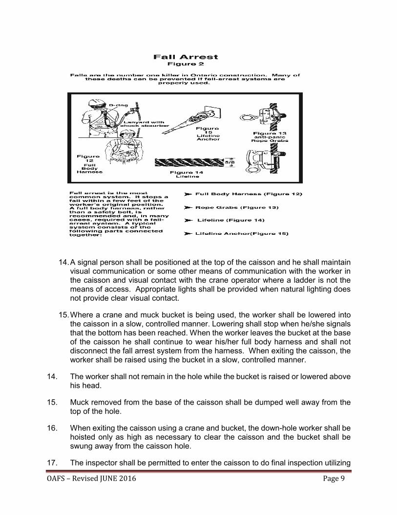
OAFS – Revised JUNE 2016 Page 9
14. A signal person shall be positioned at the top of the caisson and he shall maintain visual communication or some other means of communication with the worker in the caisson and visual contact with the crane operator where a ladder is not the means of access. Appropriate lights shall be provided when natural lighting does not provide clear visual contact.
15. Where a crane and muck bucket is being used, the worker shall be lowered into the caisson in a slow, controlled manner. Lowering shall stop when he/she signals that the bottom has been reached. When the worker leaves the bucket at the base of the caisson he shall continue to wear his/her full body harness and shall not disconnect the fall arrest system from the harness. When exiting the caisson, the worker shall be raised using the bucket in a slow, controlled manner.
14. The worker shall not remain in the hole while the bucket is raised or lowered above his head.
15. Muck removed from the base of the caisson shall be dumped well away from the top of the hole.
16. When exiting the caisson using a crane and bucket, the down-hole worker shall be hoisted only as high as necessary to clear the caisson and the bucket shall be swung away from the caisson hole.
17. The inspector shall be permitted to enter the caisson to do final inspection utilizing

OAFS – Revised JUNE 2016 Page 10
the same techniques as used for the worker doing the base cleaning. The inspector shall be trained in fall protection & confined space prior to caisson entry.
18. After any suspension in work always check that the drilled shaft is clear and the atmosphere monitored prior to resuming operations.
19. In the event that a worker becomes disabled while in the caisson, the procedures detailed under “Rescue of worker from a caisson” shall be followed.
20. A copy of this procedure will be kept available on site and copies shall be made available to all workers that are involved in caisson cleaning or inspection procedures.
Rescue of a Worker from a Caisson
1. Rescue procedures must be planned and written prior to any entry into a caisson and practiced prior to work commencing.
2. If a worker loses consciousness or is injured in the hole, do not attempt to go down the hole to rescue the unconscious/injured worker. Advise the supervisor immediately. The reason for the workers unconsciousness or injury may pose a hazard to any potential rescuer.
3. If the worker in the caisson is unconscious, initiate the rescue operation and designate someone to call 911 for assistance.
4. The injured worker shall not be left alone or unattended.
5. Supervisors are required to manage and coordinate activities until emergency services arrive on site.
6. A person is to be designated by the supervisor to direct emergency vehicles.
7. The use of either a 3-way winch self-retracting lifeline (SRL), or any other means that facilitates recovery of a disabled worker. Alternatively a winch line from the drill rig or crane may be employed as an emergency only.
8. A secondary means of hoisting the worker shall be available in the event that the crane or drill rig breaks down.
9. On recovery of the worker, perform first aid as appropriate and prepare for ambulance arrival or transportation to a hospital, if necessary.
10. Do not send workers down any other caissons until a cause of the incident is established and it can be determined that it is safe to continue operations.

OAFS – Revised JUNE 2016 Page 11
Soil Classifications and Excavations Type 1 soil most closely exhibits the following characteristics:
(a) is hard, very dense and can be penetrated only with difficulty by a small sharp object
(b) has a dry appearance (c) has no signs of water seepage (d) can be excavated only by mechanical equipment
Examples of Type 1 soils are consolidated clay, and some glacial tills. The walls should be sloped 1 to 1 or 45 degrees starting at 1.2 meters (4 feet) up the wall.
Type 2 soil most closely exhibits the following characteristics:
(b) is very stiff, dense and can be penetrated with moderate difficulty by a small sharp object
(c) is difficult to excavate with hand tools (d) has a low to medium natural moisture content and has a damp
appearance after it is excavated (e) has no signs of water seepage
Typical type 2 soils are silty clay and less dense tills. The walls should be sloped 1 to 1 or 45 degrees starting at 1.2 meters (4 feet) up the wall.
TYPE 1 & 2 SOIL
Type 3 soil most closely exhibits the following characteristics:
(a) previously excavated soil; or
(b) soil that is stiff to firm or compact to loose in consistency and has one or more of the following characteristics:
(i) It exhibits signs of surface cracking.
(ii) It exhibits signs of water seepage.
(iii) If it is dry, it may run easily into a well-defined conical pile.
Minimum Bank Slope
GOOD SOIL
Maximum 1.2 m 4 ( ft. )
Type 1 & 2 Soil

OAFS – Revised JUNE 2016 Page 12
(iv) It has a low degree of internal strength.
Other typical Type 3 soil includes sand, granular materials, and silty or wet clays. The walls should be sloped at an angle of 1 to 1or 45 degrees from the bottom of the excavation.
TYPE 3 SOIL
Type 4 soil most closely exhibits the following characteristics:
(a) is firm to very soft, loose to very loose and is easy to excavate with hand tools
(b) is cohesive soil which is sensitive and upon disturbance is significantly reduced in internal strength
(c) is dry and runs easily into a well-defined conical pile (d) has a wet appearance and runs easily or flows (e) includes Type 1, 2 or 3 granular soil below the water table (f) exerts substantial hydrostatic pressure when a support system is used (g) includes previously excavated soil, rock or other material which exhibit any
characteristic of this subsection
Typical Type 4 material includes muskeg or other organic deposits with high moisture content, quicksand, silty clays with high moisture content, and clays. The walls should be sloped at an angle of 1 to 3 from the bottom of the excavation.
Note: Unless the walls are solid rock, never enter a trench deeper than 1.2 meters 4 (feet) unless it is property sloped, shored or protected by a trench box.
TYPE 4 SOIL
Minimum Bank Slope
Type 3 Soil FAIRLY GOOD SOIL
BAD SOIL Type 4 Soil
Minimum Bank Slope
OAFS – Revised JUNE 2016 Page 13
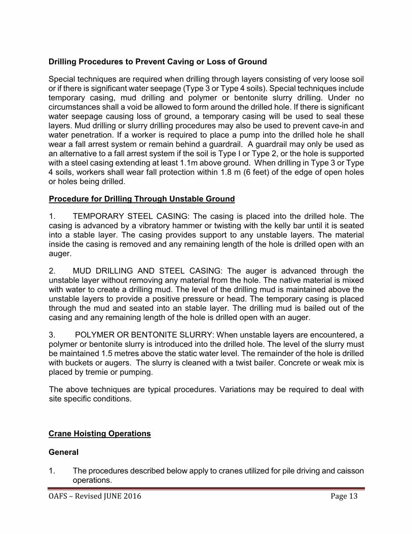
Drilling Procedures to Prevent Caving or Loss of Ground
Special techniques are required when drilling through layers consisting of very loose soil or if there is significant water seepage (Type 3 or Type 4 soils). Special techniques include temporary casing, mud drilling and polymer or bentonite slurry drilling. Under no circumstances shall a void be allowed to form around the drilled hole. If there is significant water seepage causing loss of ground, a temporary casing will be used to seal these layers. Mud drilling or slurry drilling procedures may also be used to prevent cave-in and water penetration. If a worker is required to place a pump into the drilled hole he shall wear a fall arrest system or remain behind a guardrail. A guardrail may only be used as an alternative to a fall arrest system if the soil is Type I or Type 2, or the hole is supported with a steel casing extending at least 1.1m above ground. When drilling in Type 3 or Type 4 soils, workers shall wear fall protection within 1.8 m (6 feet) of the edge of open holes or holes being drilled.
Procedure for Drilling Through Unstable Ground
1. TEMPORARY STEEL CASING: The casing is placed into the drilled hole. The casing is advanced by a vibratory hammer or twisting with the kelly bar until it is seated into a stable layer. The casing provides support to any unstable layers. The material inside the casing is removed and any remaining length of the hole is drilled open with an auger.
2. MUD DRILLING AND STEEL CASING: The auger is advanced through the unstable layer without removing any material from the hole. The native material is mixed with water to create a drilling mud. The level of the drilling mud is maintained above the unstable layers to provide a positive pressure or head. The temporary casing is placed through the mud and seated into an stable layer. The drilling mud is bailed out of the casing and any remaining length of the hole is drilled open with an auger.
3. POLYMER OR BENTONITE SLURRY: When unstable layers are encountered, a polymer or bentonite slurry is introduced into the drilled hole. The level of the slurry must be maintained 1.5 metres above the static water level. The remainder of the hole is drilled with buckets or augers. The slurry is cleaned with a twist bailer. Concrete or weak mix is placed by tremie or pumping.
The above techniques are typical procedures. Variations may be required to deal with site specific conditions.
Crane Hoisting Operations General 1. The procedures described below apply to cranes utilized for pile driving and caisson
operations.

OAFS – Revised JUNE 2016 Page 14
2. Pre-operation checks shall be performed daily before work begins to ensure that the
machine is in safe working order. Pre-Operation check is to include visual inspection of boom and the pre-use inspection shall be documented. All documentation or copies shall be kept in the crane.
3. No crane shall be subjected to a load greater than its rated load carrying capacity.
Lifting charts are to be provided and posted in all cranes. If the charts are missing or inappropriate, it is the operator’s responsibility to notify his supervisor and have them replaced.
4. All crane rigging shall be suitable for the load being lifted and all cables and rigging
shall be visually inspected daily for torn strands and visible wear by a competent worker. Slings and rigging shall be inspected before each lift. If any defects are detected they are to be taken out of service immediately.
5. A log book shall be kept with each crane and the operator shall be responsible for
making the appropriate entries in the log book. The log book shall be signed by the operator daily.
6. A signal person shall be positioned in full view of the operator where the operator's
view of the intended path of travel or any part of it or of the cranes load is obstructed or where a person may be endangered by any part of the crane or its load.
7. An effective means of communication between the workers shall be established
and maintained. The operator and front end man shall agree on the type of communication to be used prior to starting work. Hand signals must be used when verbal communication is not effective. All workers shall be familiar with machine operation hand signals, however, the Operator shall accept signals only from the designated signalman except for an emergency stop signal, which may be given by any worker. Signals are shown in Appendix D.
8. Every hoisting hook shall be equipped with a safety catch unless specifically designed and engineered without a safety latch.
9. Where ground conditions are not adequate to resist unreasonable settlement, crane mats shall be utilized to distribute the load of crawler cranes. If outriggers or other stabilizing devices are fitted to the equipment they shall rest on firm ground or mats and pads to prevent unreasonable settlement or deformation.
10. Extreme caution shall be exercised when walking with a suspended load.
11. No smoking, welding or open flame shall be allowed within 20 feet of any equipment being refuelled.
12. During hoisting, tag lines or similar devices shall be used where necessary to control rotation of the load. Only workers who are competent and familiar with the specific hazards of the operation shall be in the work areas where these operations are being carried out.
OAFS – Revised JUNE 2016 Page 15
13. Walk with care - watch your footing. Never walk or work under crane booms or suspended loads. Remove slings in a manner so as not to endanger workmen.
14. When entering crane cab, operator should scrape mud off boots to avoid slipping on foot pedals. Do not leave the crane by jumping off the tracks – use proper 3-point contact.
15. No suspended load should be left unattended by the operator. Never leave any of the equipment with the motor running unless the master clutch is disengaged.
16. Standing on the walkway or in the cab of the crane talking to the operating engineer while the crane is operating is Strictly Prohibited.
17. Never stand or sit on the crawlers of the crane. The operator may not know that you are there.
18. When operating a crane on slippery surfaces such as hard-packed snow or ice, extreme caution shall be exercised to prevent sliding.
19. Cranes shall not be operated where any part of the crane could potentially encroach the minimum safe distances from overhead utilities. Refer to table on page 4.
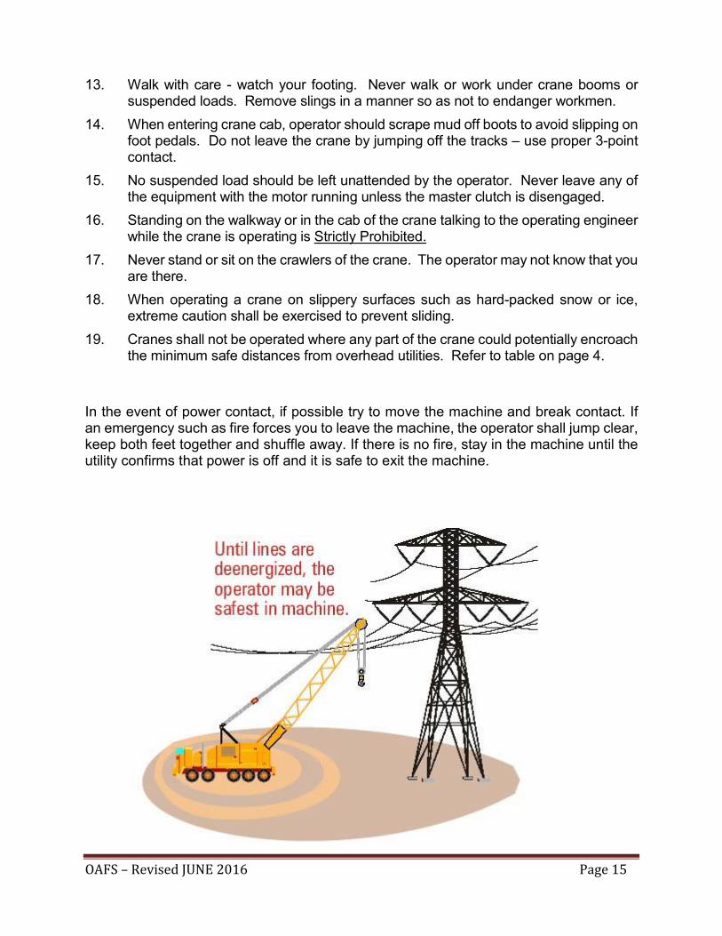
In the event of power contact, if possible try to move the machine and break contact. If an emergency such as fire forces you to leave the machine, the operator shall jump clear, keep both feet together and shuffle away. If there is no fire, stay in the machine until the utility confirms that power is off and it is safe to exit the machine.

OAFS – Revised JUNE 2016 Page 16
If status of a power line is unknown, assume line is energized and investigate to determine voltage so that minimum safe distances can be maintained. Orange insulators are not guards on the overhead utilities. They are simply a visual indicator to more easily identify the overhead hazard.
20. When moving/swinging equipment be sure that all cables are secured, especially near power lines. The signalman shall alert the operator if any part of the equipment or load approaches the minimum distance outlined above.
21. Appropriate warning signage as required by legislation is to be posted at the operator station and shall also be positioned outside in the vicinity of the hazard.
22. DO NOT ride on the hook of the pile line or any sling.
23. In jurisdictions where crane operator licensing is the law (this includes the Province of Ontario), cranes must only be operated by persons who hold a proper Certificate of Qualification or License. (This rule does not apply to an apprentice being instructed by a licensed operator.)
Procedure for Driving Piles 1. Where the boom, counterweight or other principal part of a crane has been modified
to accept equipment related to pile driving (i.e. leads, hammers, etc.), the modification shall be the subject of an engineered drawing.
2. No person shall stand under the kicker (the strut between the crane and the pile
leads). 3. When driving piles in a side batter configuration, ensure that the equipment is
suitable for the intended batter.
4. A signal person shall be positioned in full view of the operator before any pile driving equipment is relocated at the work site. Standard crane and pile driving signals must be used by all workers. The ooperator shall accept signals only from the designated signalman except for an emergency stop signal, which may be given by any worker. Standard Signals are shown in Appendix D.
5. Piles or sheet piling stored on the ground shall be adequately supported by blocking.
Pipe piles must be stacked in well supported and braced racks or frames, unless other provision is made to prevent their movement.

OAFS – Revised JUNE 2016 Page 17
6. During hoisting, tag lines or similar devices shall be used where necessary to control rotation of the load. Piles or sheet piling shall be adequately supported during placing or removal. Only workers who are competent and familiar with the specific hazards of the operation shall be in the work area where these operations are being carried out.
7. Ensure that all foreign material such as frozen earth or tack-welded steel is removed
from the piles before being spotted for driving. 8. If a worker is required to climb the driving lead, the operator of the equipment will
apply all brakes and necessary safety switches to ensure no uncontrolled motion of the equipment. Appropriate fall arrest system must be worn,
9. All workers shall wear eye-protection and hearing protection.
10. Secure all shackles with steel wire or other means.
11. Workers required to take pile refusal measurements shall be made aware of potential hazards.
Driving Lead Climbing Procedure
If operations necessitate a person to climb the driving lead, the following safety precautions must be strictly adhered to. Wherever possible, a mobile aerial work platform is strongly recommended and climbing a lead should always be considered a last resort. A site-specific procedure which includes training for all crew members and approval by senior management is also strongly recommended. 1. The person climbing shall wear a full body harness with climbing and positioning
lanyards attached. It must be inspected prior to each use.
2. The climbing person will attach the double-legged lanyard (Y-shaped) webbing end to the dorsal or sternal ring of the harness.
3. He will approach the leads and reach up above his head and attach one of the lanyard locking snaps to the lead in one of the 1” dia. holes drilled for this purpose. (Make sure that the attachment points are chosen wisely, the life of the person climbing will depend on it if there is a fall.)
4. Climb upward to a point where the first lanyard snap is located at about waist level, stop climbing, reach up with the second lanyard locking snap and fasten it securely to a 1” hole. Reach out to the first lanyard locking snap and unhook it after ensuring that the second lanyard locking snap is securely fastened. Continue to climb upward to a point where the second lanyard snap is located at about waist level, stop climbing, reach up with the first lanyard locking snap and fasten it securely. Reach out to the second lanyard locking snap and unhook it.
5. Repeat this method of climbing until the desired height location is reached. Securely anchor off using a work positioning lanyard attached to the two (2) rings, one on

OAFS – Revised JUNE 2016 Page 18
each side of harness or a lanyard attached to a front ring, and perform the task required. Keep one lanyard attached to the lead above your head at all times when performing task.
6. Upon completion of task, begin to descend to a point where the secured lanyard locking snap is still reachable overhead, stop descending, reach out and attach the other lanyard snap at about waist height. Reach up and unhook the first locking snap.
7. Continue to descend until the second attached locking device is still reachable overhead. Stop descending, reach out and re-attach the first locking snap at about waist height. Reach out and unhook the second locking snap.
8. Repeat this descent method until ground level is reached. At that point, detach all lanyard locking snaps and stand clear of the leads before removing safety gear.
9. Remove all safety gear and return it to the safe, dry storage location away from sunlight and exposure to petroleum products. If at any time the safety gear is damaged or broken, it shall be removed from service.
Lead Climbing Rescue Procedure
Note: This procedure utilizes an engineered controlled descent device, a device which employs a friction system to lower the rope at a controlled slow rate. Again, as with climbing a lead for operational purposes, rescue via climbing is also strongly discouraged in favour of rescue with a mobile aerial work platform. Climbing should always be a considered a last resort. If someone who has climbed the lead becomes incapacitated and requires rescue, proceed as follows:
1. First, take a few seconds to view the situation to discern if, by ground observation, some simple directions can assist the endangered climber to reposition himself to a secure location and not require rescue.
2. If, by observation, rescue is required, call 911 and proceed with the rescue operation pending arrival of 911 personnel. Retrieve the rescue rope with the engineered controlled descent device. Give the front end of the rescue rope with the attached hook and descent device installed to the person making the ascent. The bottom end of the rope is to remain on the ground.
3. The person to perform the rescue climb must don the harness and two-legged lanyard. He will attach the rescue rope and assembly to himself and begin to ascend, utilizing the two-legged lanyard as follows: at ground level, reach up and attach one of the lanyard locking snaps in a hole near the extent of his reach. Climb up until the attached snap is at about waist level. Stop climbing, reach up and attach the second lanyard snap and fasten it in a hole within reach. Reach out and unhook the first snap and continue to climb.

OAFS – Revised JUNE 2016 Page 19
Never unhook a lanyard locking snap until the other is securely fastened.
4. The rescue person shall climb and securely attach the snap at the end of the rope from the controlled descent device in the hole above the incapacitated person.
5. Attach a 4’ or 5’ lanyard to the incapacitated person from the dorsal or sternal ring of his harness through the bottom end of the controlled decent device. This is the complete Fall Arrest Rescue system.
6. After ensuring that the system is holding and the incapacitated person is securely supported by the rescue system, the rescuer should release or cut the incapacitated persons’ original lanyard and release the rope from around the locking hook of the device.
7. The incapacitated person will start to descend slowly.
8. If the rate of descent is too slow, the rescuer may apply some pressure by placing his hand around the device and pulling down, to increase the speed of descent.
9. The rescuer shall descend using the procedures outlined in the double lanyard ascent procedure, reversed, until he reaches the ground.
10. The worker on the ground must be alert and ensure that the rescue rope is not being tangled and/or twisting around the incapacitated person as he is lowered, until he reaches the ground.
11. Check all safety equipment for imperfections, if one is found “REPORT IT” before you store it. If none are found return the safety equipment to the clean dry storage location until it is needed again.
12. Any harness and lanyards that have been subjected to a fall must be replaced even if they look fine. It should be immediately removed from service and destroyed.
13. Workers shall be trained in the Lead Climbing Rescue procedure. – One person from the crew shall be designated as the rescuer. This person shall not be the person who normally climbs the lead. This worker shall be trained in the use of the device.
14. This procedure may be modified if necessary to suit the specific type of controlled descent device used.

OAFS – Revised JUNE 2016 Page 20
Vibratory Hammers
1. Crane operators must inspect boom sections for cracks or other damage on a daily basis.
2. Check all bolts and suspension cables on a daily basis.
3. When the hammer is shut off the boom will vibrate. When extracting piling shut off the hammer when the bottom of the casing or pile is still partially socketed in the ground.
4. Stay away from casing or pile when the hammer is vibrating. Be aware that the ground may become unstable from vibrations.
5. Always use a pile line attached directly to the casing or pile.
6. Check pile tops, handling holes, and splices of casings for damage from driving. Do not use a casing with cracks.
7. Secure all shackles with steel wire or other means.

OAFS – Revised JUNE 2016 Page 21
APPENDIX A
WARNING BARRIERS & PHYSICAL BARRICADES
EXAMPLES
1. Engineered 3-sided modular frame.
2. Engineered modular frames expandable to suit hole size.
3. Oversized liner section.
4. Scaffold frames, suitably anchored.

OAFS – Revised JUNE 2016 Page 22
APPENDIX B
TEMPORARY FIXED SUPPORTS
EXAMPLES
The fixed support utilized for workers to tie-off to should be located away from the swing area of the drill and auger.
1. Precast concrete block with attachment point.
2. Concrete-filled liner section with attachment point.
3. Jersey Barrier with attachment point.
4. Auger screwed into ground 1 flight.
5. Existing structural members where available.
6. Adjacent installed soldier piles.

OAFS – Revised JUNE 2016 Page 23
APPENDIX C
TEMPORARY HOLE COVERS
1. Steel plate
2. Steel circular donut with grating over hole.
3. Plywood and lagging, secured or weighted down.
4. Other devices, such as: - extended casing in lieu of cover - auger positioned over top of hole, making access impossible
- adequate fence or guardrail

OAFS – Revised JUNE 2016 Page 24
APPENDIX D CRANE & PILEDRIVING SIGNALS

OAFS – Revised JUNE 2016 Page 25

OAFS – Revised JUNE 2016 Page 26
PILE DRIVING SIGNALS