ontology-based model integration for the conceptual design ... · ontology-based model integration...
TRANSCRIPT
TECHNISCHEN UNIVERSITAT MUNCHEN
Forschungs- und Lehreinheit I
Angewandte Softwaretechnik
Ontology-based Model Integration for
the Conceptual Design of Aircraft
Martin Glas
Vollstandiger Abdruck der von der Fakultat fur Informatik der Technischen UniversitatMunchen zur Erlangung des akademischen Grades eines
Doktors der Naturwissenschaften (Dr. rer. nat.)
genehmigten Dissertation.
Vorsitzender: Univ.-Prof. Dr. Ernst W. Mayr
Prufer der Dissertation: 1. Univ.-Prof. Bernd Brugge, Ph.D.
2. Univ.-Prof. Dr. Mirko Hornung
Die Dissertation wurde am 31.01.2013 bei der Technischen Universitat Muncheneingereicht und durch die Fakultat fur Informatik am 17.04.2013 angenommen.


Acknowledgements
I am deeply grateful to Prof. Bernd Brugge, Ph.D. for his advice andencouragement during the development of this dissertation.I am also very thankful to Prof. Mirko Hornung and Dr. GernotStenz for their trust in and support of my dissertation at BauhausLuftfahrt.I would also like to thank Dr. Steffen Prochnow, Dr. Daniel Ratiu,Dr. Sven Ziemer, and the colleagues at the Chair of Applied SoftwareEngineering for their valuable and constructive feedback.Last but not least, I would like to thank my co-workers at BauhausLuftfahrt for their belief in interdisciplinary research, in particularClement Pornet, Dr. Arne Seitz, Hans-Jorg Steiner, and Dr. KerstinWieczorek, who readily contributed their time and expertise asparticipants and user interface reviewers for my case studies.

Abstract
The development of a new aircraft begins with the conceptual design phase which aims toincorporate the latest technologies and methods into a novel design and its assessment.The development process is usually distributed across several teams which concurrentlycreate models with overlapping content. If overlapping model parts are refined in onemodel without immediate propagation of the refinements to the other models, theybecome inconsistent. Exchanging model parts is, however, hampered due to the het-erogeneity of these models resulting from discipline-specific modeling approaches. Cur-rently, there are two approaches to tackling this problem: a clear separation of concernsbetween models to avoid overlapping content and standardized data formats which allowdesigners to exchange model parts. However, clear separation of design models is diffi-cult to establish during conceptual aircraft design, as the contributing disciplines haveconsiderably overlapping concerns in this phase. Accordingly, overlapping content of de-sign models is unavoidable. Therefore, the problem of consistency and model exchangeis addressed by standardized data formats which are interpreted by different tools in thesame way. However, conceptual aircraft designers mostly use generic data formats whichenable the high degree of flexibility required for this early and explorative phase of de-sign. However, as domain-specific concepts and structures are deliberately not specifiedby these formats, the meaning of object names and the model decomposition remainsimplicit knowledge. Therefore, overlapping content and conflicts between models cannotbe identified automatically. As a consequence, the maintenance of consistency remainsan inefficient and error-prone task. Furthermore, the exchange of concept model partsbetween disciplines contributing to the same project, and the reuse of existing legacymodels is still not well supported by tools.
This dissertation describes a semiautomated ontology-based approach for model inte-gration. An essential part of this approach is the Oida framework which uses a domain-specific reference ontology to facilitate semiautomated consolidation of overlapping con-tent and exchange of selected non-overlapping content between discipline-specific models.Thereby, the owners of the different models map their model elements to the referenceontology. The Oida framework evaluates these mappings, identifies matching model ele-ments, and supports the model owners in resolving conflicts and in optionally importingparts from other models. These capabilities of the Oida framework were evaluated infive quasi-experiments and six case studies using a prototypical implementation of theOida framework and real sample models originating from different conceptual aircraftdesign tools. The aircraft designers who operated the prototype during case studies wereable to use the framework without help and considered the automatically generated re-sults to be correct from their professional point of view. The solution presented in thisdissertation not only contributes to a more automated integration of aircraft models butalso to a better collaboration during the interdisciplinary process of conceptual aircraftdesign.

Zusammenfassung
Die Entwicklung eines neuen Flugzeugskonzepts ist ein interdisziplinarer Prozess, indem so fruh wie moglich neueste Technologien und Methoden aus den verschiedenenFachbereichen in den Entwurf einfließen. Da die Modelle, welche in den verschiedenenFachbereichen entstehen, gewohnlich eine große inhaltliche Uberlappung aufweisen undgleichzeitig getrennt voneinander mit unterschiedlichem Schwerpunkt verfeinert werden,entstehen Inkonsistenzen. Außerdem erschwert die Heterogenitat der Modelle, die aufGrund von unterschiedlichen Herangehensweisen der Fachbereiche entsteht, einen effizi-enten Modellaustausch. Gegenwartig gibt es zwei Ansatze, diesen Problemen zu begeg-nen: Eine starke inhaltliche Abgrenzung von Modelle und standardisierte Datenformate,um in den unterschiedlichen Fachbereichen dieselben Daten verwenden zu konnen. Einestarkere inhaltliche Abgrenzung von Modellen, ist insbesondere im Flugzeugkonzeptent-wurf schwer moglich, da sich hier die beitragenden Fachbereiche stark uberschneiden.Inhaltliche Uberlappungen zwischen den Modellen sind daher nicht vermeidbar. Daherversucht man durch den Einsatz von standardisierten Datenformaten Konsistenz und Da-tenaustausch zwischen den Modellen effizient zu realisieren, da sie von Werkzeugen gleichinterpretiert werden. Allerdings werden im Fugzeugkonzeptentwurf eher generische Stan-darddatenformate verwendet, um ein hohes Maß an Flexibilitat zu ermoglichen. Da dieseFormate bewusst keine konkreten Konzepte und Strukturen aus den Fachbereichen defi-nieren, bleibt die Semantik der Namensgebung und des Modellaufbaus implizites Wissen.Inhaltliche Uberlappungen und Konflikte konnen so nicht automatisch erkannt werden.Die daher erforderliche manuelle Arbeit macht den Abgleich von Konzeptmodellen inef-fizient und fehlertrachtig. Außerdem wird der gegenseitige Modellaustauch zwischen denFachbereichen desselben Projekts oder die Wiederverwendung von existierenden Model-len aus vorhergehenden Projekten von Werkzeugen kaum unterstutzt.
In dieser Dissertation wird ein Ontologie-basierter Ansatz zur Modellintegration vor-gestellt. Ein essenzieller Bestandteil dieses Ansatzes ist das Oida Framework, welcheseine fachgebietsspezifische Referenzontologie einsetzt, um den Automatisierungsgrad beider Integration von Systemstrukturmodellen aus dem Flugzeugentwurf zu erhohen. Je-der Modellverwalter verknupft sein Modell mit Konzepten der Referenzontologie. DasOida Framework wertet diese Verknupfungen aus und erkennt so automatisch inhalt-liche Uberlappungen und Konflikte. Daruber hinaus ermoglicht das Framework demModellverwalter, augewahlte Teile eines anderen Modells in sein Modell zu ubertragen.Diese Fahigkeiten des Oida Frameworks wurden durch eine prototypische Implemen-tierung in sechs Fallstudien und funf Quasi-Experimenten mit Ergebnissen evaluiert.Dabei wurden echte Flugzeugmodelle als Testobjekte verwendet, die aus Werkzeugenmit unterschiedlichendem inhaltlichem Schwerpunkt stammen. Die Luftfahrtingenieure,welche an diesen Fallstudien als Modellverwalter teilnahmen, konnten den Prozess weit-gehend selbstandig durchfuhren und hielten die automatisch generierten Ergebnisse ausfachlicher Sicht fur korrekt. Die vorgestellte Losung steigert den Automatisierungsgradbei der Modellintegration von Flugzeugkonzeptmodellen wodurch die Zusammenarbeitzwischen den Fachdisziplinen im Flugzeugentwurfsprozess wesentlich verbessert werdenkann.

Contents
1. Introduction 11.1. Current Practice . . . . . . . . . . . . . . . . . . . . . . . . . . . . . . . . 31.2. Ontology-based Model Integration: Overview . . . . . . . . . . . . . . . . 5
1.2.1. Match Models Use Case . . . . . . . . . . . . . . . . . . . . . . . . 71.2.2. Merge Models Partially . . . . . . . . . . . . . . . . . . . . . . . . 81.2.3. Co-Evolve Integration Artifacts Use Case . . . . . . . . . . . . . . 81.2.4. Research Questions . . . . . . . . . . . . . . . . . . . . . . . . . . . 91.2.5. Scoping . . . . . . . . . . . . . . . . . . . . . . . . . . . . . . . . . 9
1.3. Research Process and Outline . . . . . . . . . . . . . . . . . . . . . . . . . 12
2. Terminology 132.1. Equivalence . . . . . . . . . . . . . . . . . . . . . . . . . . . . . . . . . . . 132.2. Mereology . . . . . . . . . . . . . . . . . . . . . . . . . . . . . . . . . . . . 152.3. Technological Spaces . . . . . . . . . . . . . . . . . . . . . . . . . . . . . . 17
3. Problem Definition and Related Work 213.1. Sample Models . . . . . . . . . . . . . . . . . . . . . . . . . . . . . . . . . 213.2. Oida Requirements and Constraints . . . . . . . . . . . . . . . . . . . . . 243.3. Related Work . . . . . . . . . . . . . . . . . . . . . . . . . . . . . . . . . . 26
3.3.1. Tool and Model Integration . . . . . . . . . . . . . . . . . . . . . . 263.3.2. Ontology Generation and Matching . . . . . . . . . . . . . . . . . 283.3.3. Evolution of Coupled Artifacts . . . . . . . . . . . . . . . . . . . . 28
4. The Oida Functional Model 314.1. The Model Matching Capability . . . . . . . . . . . . . . . . . . . . . . . 314.2. The Partial Model Merge Capability . . . . . . . . . . . . . . . . . . . . . 404.3. The Co-Evolution Capability . . . . . . . . . . . . . . . . . . . . . . . . . 41
5. The Oida Analysis Object Model 515.1. Analysis Objects of the Match Models Use Case . . . . . . . . . . . . . . 515.2. Analysis Objects of the Ontology-based Model Transformation TM . . . . 525.3. Analysis Objects of Merge Models Partially Use Case . . . . . . . . . . . 585.4. Analysis Objects of Co-Evolve Integration Artifacts Use Case . . . . . . . 66
6. The Oida Framework Design 716.1. Design Goals and Architecture . . . . . . . . . . . . . . . . . . . . . . . . 716.2. Platform Layer . . . . . . . . . . . . . . . . . . . . . . . . . . . . . . . . . 72
ix
Contents
6.3. Provider Layer . . . . . . . . . . . . . . . . . . . . . . . . . . . . . . . . . 726.4. Transformation Layer . . . . . . . . . . . . . . . . . . . . . . . . . . . . . 796.5. Service Layer . . . . . . . . . . . . . . . . . . . . . . . . . . . . . . . . . . 806.6. Application Layer . . . . . . . . . . . . . . . . . . . . . . . . . . . . . . . . 876.7. Oida Knowledge Sources: Overview . . . . . . . . . . . . . . . . . . . . . 91
7. Evaluation 977.1. Evaluation Design . . . . . . . . . . . . . . . . . . . . . . . . . . . . . . . 977.2. Empirical Studies . . . . . . . . . . . . . . . . . . . . . . . . . . . . . . . . 99
7.2.1. Evaluation of the Transformation TMO . . . . . . . . . . . . . . . . 1007.2.2. Evaluation of the Model Matching Capability . . . . . . . . . . . . 1047.2.3. Evaluation of the Partial Models Merge Capability . . . . . . . . . 1107.2.4. Evaluation of the Co-Evolution Capability . . . . . . . . . . . . . . 1147.2.5. Threats to Validity . . . . . . . . . . . . . . . . . . . . . . . . . . . 120
7.3. Results . . . . . . . . . . . . . . . . . . . . . . . . . . . . . . . . . . . . . . 120
8. Conclusion and Outlook 1238.1. Contributions . . . . . . . . . . . . . . . . . . . . . . . . . . . . . . . . . . 1238.2. Integrating other Dimensions of Conceptual Models . . . . . . . . . . . . 126
A. Implementation of the Oida Prototype 127A.1. Selection of Basic Frameworks . . . . . . . . . . . . . . . . . . . . . . . . . 127A.2. ModelProvider Plug-in . . . . . . . . . . . . . . . . . . . . . . . . . . . . . 129A.3. OntologyProvider Plug-in . . . . . . . . . . . . . . . . . . . . . . . . . . . 130A.4. Transformation Plug-in . . . . . . . . . . . . . . . . . . . . . . . . . . . . 131A.5. Matching Plug-in . . . . . . . . . . . . . . . . . . . . . . . . . . . . . . . . 134A.6. Merging Plug-in . . . . . . . . . . . . . . . . . . . . . . . . . . . . . . . . 135A.7. Evolution Plug-in . . . . . . . . . . . . . . . . . . . . . . . . . . . . . . . . 136A.8. MatchingApp Plug-in . . . . . . . . . . . . . . . . . . . . . . . . . . . . . 136A.9. MergingApp Plug-in . . . . . . . . . . . . . . . . . . . . . . . . . . . . . . 137
B. Implementation of the Reference Ontology Prototype 141
x
Contents
Typographical Conventions
Throughout this dissertation the following conventions are used:
• Citations are given in a comprehensive form (e.g. [ABC08]), indicating the firstthree authors (e.g. Alpha, Bravo, Charlie) of an article by capital letters followedby the year of publication (2008). If a “+” appears in the citation, then more thanthree authors have contributed. In the case of a single author, the first letter ofhis last name is written in capitals, followed by two further lower case letters.
• The Unified Modeling Language (UML) is used for diagrams illustrating softwarecomponents.
• The typewriter typeface is used for names of software analysis and design objects,such as RenamerStrategy.
• Other technical terms and concept terms are written in italics when they appearfor the first time.
• Lower capitals are used for product names, such as Eclipse.
xi

1. Introduction
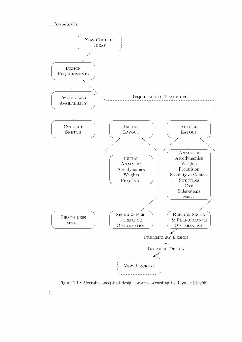
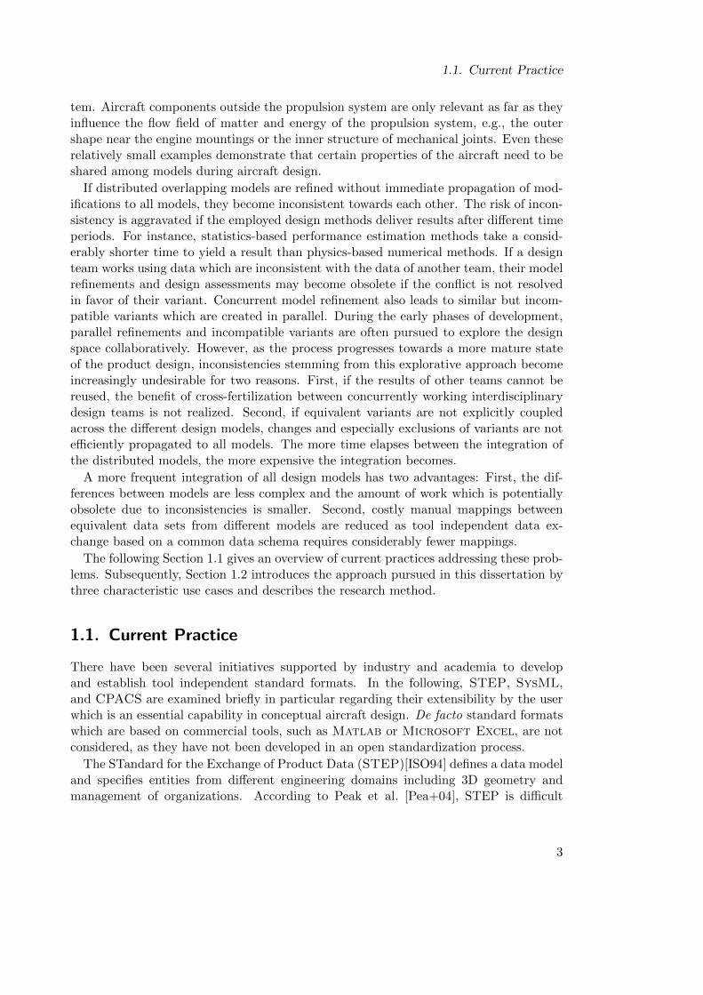
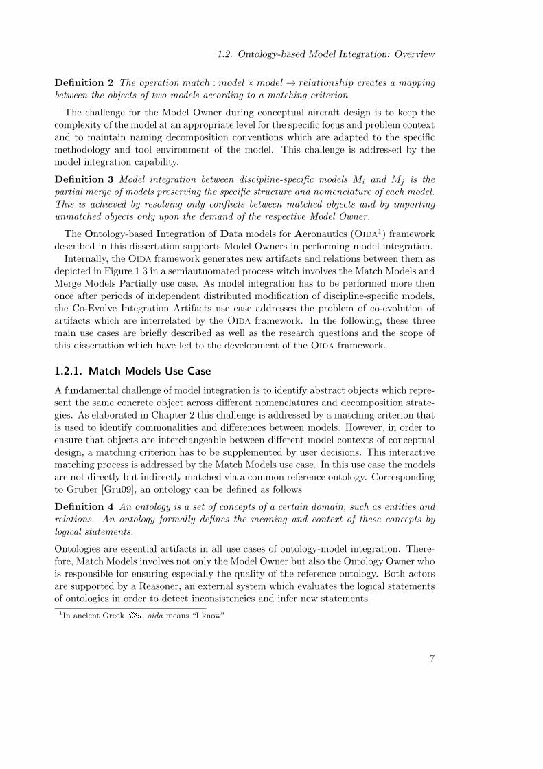
The development process which begins with a first product idea and eventually leads tothe blueprints for a new aircraft is usually divided into three phases: conceptual, prelim-inary, and detailed design. According to Raymer [Ray06] the objective of the conceptualdesign phase is the development of layouts and assessments of distinct design alterna-tives addressing a common set of requirements. Thereby, the design space is exploredby an iterative process of requirements engineering, analysis, sizing, optimization, anddownselection of technologies and architectures. As depicted in Figure 1.1, the aircraftmodel is refined involving an increasing number of disciplines specialized in certain as-pects of aircraft design. The next phase begins after one concept has been selected tobe elaborated and scrutinized in the preliminary design phase. In order to prepare forthe decision on whether to build the product, the selected design alternative is refinedand validated by more sophisticated numerical methods and small-scale physical exper-iments. If the decision is made to build the aircraft, the following detailed design phaseresults in all the documents required for the realization of the new aircraft.
Compared to the later design phases, conceptual aircraft design has a high level ofdesign freedom but a low level of model detail and fidelity as it has to rely entirely on si-mulation and legacy models which have been validated and calibrated against previouslybuilt products. However, these legacy models need to be adapted to the new product byreconfiguration and extension. Modification and recombination resulting from new fea-tures of the aircraft require a revalidation of the newly created concept model to ensureits credibility. Due to the intentional volatility of the layout during conceptual design,conceptual models are not validated by physical experiments, such as wind tunnel tests.Instead, the credibility of the concept model is increased by applying more sophisticatedestimation and simulation methods. The efficient application of these methods requiresexpert knowledge in certain disciplines. In general, a discipline is a part of a scientific do-main. The context of conceptual aircraft design is typically associated with engineeringdisciplines, such as aerodynamics, structural mechanics, and thermodynamics. However,an aircraft concept is also driven by non-engineering disciplines, such as economics andpsychology. Each of these disciplines models an aircraft with overlapping scope, thussharing methods, terminology, and tools. For instance, most disciplines model the outershape of the aircraft. Aerodynamics examines effects of fluids on the outer shape of theaircraft while the inner structure is generally not relevant. Structural mechanics focuseson the effects of loads to the inner structure of the aircraft which implicitly defines theouter shape. Accordingly, the discipline of structural mechanics shares model parts withaerodynamics such as aerodynamic loads, but for a different purpose. Currently, mostaircraft propulsion systems are based on the conversion of thermal to mechanical energy.Therefore, the discipline of thermodynamics is the main driver of the propulsion sys-
1
1. Introduction
DesignRequirements
New ConceptIdeas
TechnologyAvailability
ConceptSketch
InitialLayout
RevisedLayout
InitialAnalysis:
AerodynamicsWeights
Propulsion
Analysis:Aerodynamics
WeightsPropulsion
Stability & ControlStructures
CostSubsystems
etc. . .
Refined Sizing& Performance
Optimization
Sizing & Per-formance
Optimization
First-guesssizing
Preliminary Design
Detailed Design
New Aircraft
Requirements Trade-offs
Figure 1.1.: Aircraft conceptual design process according to Raymer [Ray06]
2
1.1. Current Practice
tem. Aircraft components outside the propulsion system are only relevant as far as theyinfluence the flow field of matter and energy of the propulsion system, e.g., the outershape near the engine mountings or the inner structure of mechanical joints. Even theserelatively small examples demonstrate that certain properties of the aircraft need to beshared among models during aircraft design.
If distributed overlapping models are refined without immediate propagation of mod-ifications to all models, they become inconsistent towards each other. The risk of incon-sistency is aggravated if the employed design methods deliver results after different timeperiods. For instance, statistics-based performance estimation methods take a consid-erably shorter time to yield a result than physics-based numerical methods. If a designteam works using data which are inconsistent with the data of another team, their modelrefinements and design assessments may become obsolete if the conflict is not resolvedin favor of their variant. Concurrent model refinement also leads to similar but incom-patible variants which are created in parallel. During the early phases of development,parallel refinements and incompatible variants are often pursued to explore the designspace collaboratively. However, as the process progresses towards a more mature stateof the product design, inconsistencies stemming from this explorative approach becomeincreasingly undesirable for two reasons. First, if the results of other teams cannot bereused, the benefit of cross-fertilization between concurrently working interdisciplinarydesign teams is not realized. Second, if equivalent variants are not explicitly coupledacross the different design models, changes and especially exclusions of variants are notefficiently propagated to all models. The more time elapses between the integration ofthe distributed models, the more expensive the integration becomes.
A more frequent integration of all design models has two advantages: First, the dif-ferences between models are less complex and the amount of work which is potentiallyobsolete due to inconsistencies is smaller. Second, costly manual mappings betweenequivalent data sets from different models are reduced as tool independent data ex-change based on a common data schema requires considerably fewer mappings.
The following Section 1.1 gives an overview of current practices addressing these prob-lems. Subsequently, Section 1.2 introduces the approach pursued in this dissertation bythree characteristic use cases and describes the research method.
1.1. Current Practice
There have been several initiatives supported by industry and academia to developand establish tool independent standard formats. In the following, STEP, SysML,and CPACS are examined briefly in particular regarding their extensibility by the userwhich is an essential capability in conceptual aircraft design. De facto standard formatswhich are based on commercial tools, such as Matlab or Microsoft Excel, are notconsidered, as they have not been developed in an open standardization process.
The STandard for the Exchange of Product Data (STEP)[ISO94] defines a data modeland specifies entities from different engineering domains including 3D geometry andmanagement of organizations. According to Peak et al. [Pea+04], STEP is difficult
3
1. Introduction
to extend for an individual solution outside the standard approval process. A partof the STEP standard is the data modeling language EXPRESS. There are differentrepresentation standards for the EXPRESS language. ISO 10303-21 defines an ASCIcharacter-based syntax whereas ISO 10303-28 specifies an XML schema. ISO 10303-25specifies bindings between Express and XMI which is used as an XML syntax for UMLmodels. Aircraft concepts are usually not modeled using STEP as it is not an openstandard which can be extended by the user without losing tool support. Indeed, STEPis commonly used to transfer geometry data, as most CAD tools support the standard.However, the mapping of the entire tool-specific geometry model to the STEP standardis usually not bijective. Therefore, round-trip engineering via STEP can lead to dataloss.
The Unified Modeling Language (UML) is predominantly used in the domain of soft-ware engineering and well supported by several Computer Aided Software Engineering(CASE) tools. The user can extend UML by profiles. For instance, the Systems Mod-eling Language (SysML) [Gro12] was developed as a profile for systems engineering.Unlike STEP, SysML and UML are not designed to mediate between different toolsas an exchange data format. They are standardized modeling languages which systemdevelopers can use directly throughout the development process. Currently, SysML iscommonly used in academia and industry especially for the development of embeddedsystems. For instance, spacecraft designers use SysML not only for the development ofembedded systems but also for the overall spacecraft. In contrast, designers of aircraftconcepts have rarely adopted SysML because its concepts are not well applicable tomodeling essential features of an aircraft and its mission.
The German National Aerospace Center (DLR) has recently issued the CommonParametric Aircraft Configuration Schema (CPACS), an XML schema for dataexchange between aerospace related tools [Boh12]. The schema defines standard datatypes and data structures which are commonly used in aerospace models. Furthermore,aircraft designers are provided with aircraft-specific concepts. Thereby, the designerscan model an aircraft complying to a schema which has standardized semantics by con-vention. The data structure, however, is limited to the conventional civil transportaircraft configuration. If an aircraft designer wants to model unconventional aircraftcomponents and configurations, such as electric motors or a blended wing body config-uration, he cannot extend the schema in such a way that other clients can interpret itunambiguously.
STEP, SysML, and CPACS define schemata of data types and a standard decompo-sition of exchange files. The semantics of the data are defined implicitly by convention.However, none of these standards allows the user of the schema to define user exten-sions formally, e.g., by logical statements, which can be interpreted by existing tools.Therefore, the standard can only be extended by an agreement on a new schema whichhas to be ratified by tool developers. An exchange standard for a particular domain,such as conceptual aircraft, design is created in a trade-off between domain specificityand general applicability. The more concepts a schema comprises the more difficult itis to attain an agreement to a standard. Narrowing the scope is also not viable for anexchange standard in a multidisciplinary development process.
4
1.2. Ontology-based Model Integration: Overview
Within the context of conceptual aircraft design the aforementioned exchange formatsare supported weakly by tools regarding aircraft specific concepts. Therefore, the de-signers have to manually map every data object to an equivalent object in the exchangeformat.
More generic de facto standard model data formats provided by commercial tools likeMatlab or Excel are easier to agree upon. However, a generic standard allows thedesigners to interpret the format’s constructs differently. In particular, a generic for-mat allows designers to use different naming conventions and data model decompositionstrategies. Tools depend on formal semantics of the standard and its extension mecha-nism to allow designers to adapt a tool to their particular domain. The current modelinglanguages and exchange standards are not supported by formal semantics. Accordingly,domain-specific extensions of generic modeling languages like SysML for the domainof aircraft design or the extension of existing domain-specific standards like CPACSfor unconventional system architectures are mostly established by conventions and styleguides within an organization.
In a design environment where the meanings of data objects are more informallydefined than explicitly specified by the exchange format, tools hardly support the keepingof distributed design models consistent, especially in the likely event that the structureof the designed aircraft is changed fundamentally. As a consequence, the matchingbetween objects from different design models is currently a tedious and error-pronetask for domain experts. Furthermore, this practice limits the model complexity andflexibility supported by tools, which in turn limits aircraft designers in their explorationof the design space and in the evaluation of novel concepts.
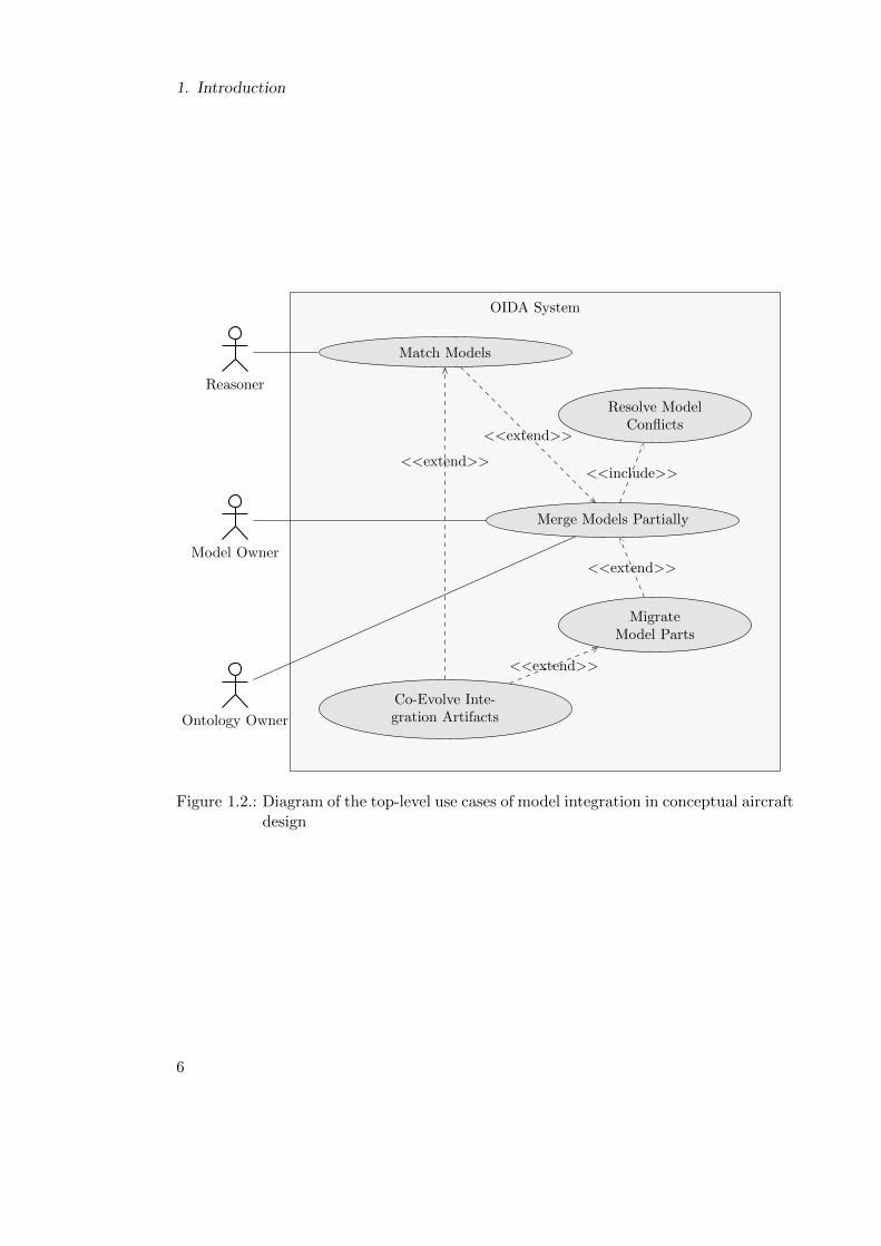
1.2. Ontology-based Model Integration: Overview
Ontology-based model integration supports an interdisciplinary development process bymaking discipline-specific models consistent and facilitating exchange of model partsbetween them. The following section defines the basic use cases of ontology-based modelintegration.
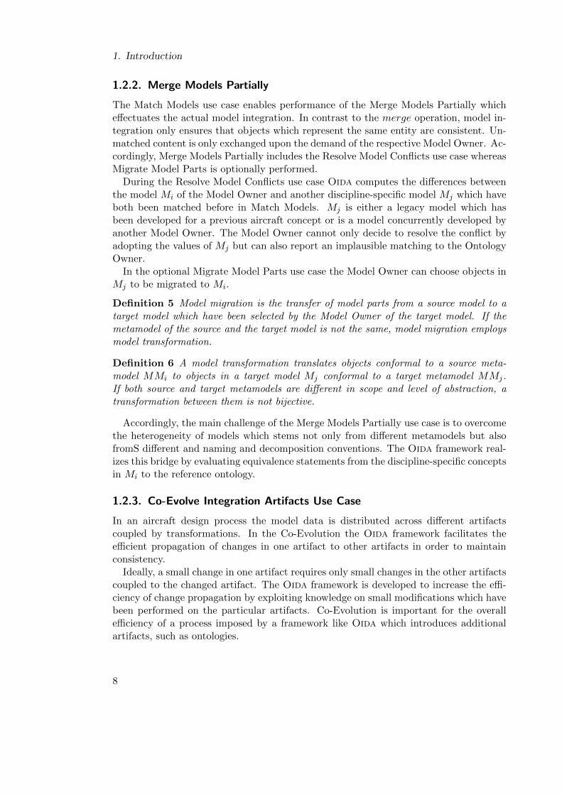
During the conceptual aircraft design process different models are created which haveoverlapping scopes but are focused on specific aspects of the aircraft concept. In general,each model has a Model Owner. The Model Owners have to ensure that their respectivemodel is not only consistent with the other models within the interdisciplinary designprocess, but also have to decide whether to import more detailed parts from anothermodel. This task is called model integration in order to reflect that models are not onlyconsolidated but partly exchanged. Model integration is similar to the model mergeoperation described by Brunet et al. [Bru+06].
Definition 1 The operation merge : model × model × relationship → relationshipcreates a consistent union of two given models. Model merge includes the resolution ofconflicts between overlapping elements from the source models.
Model merge requires a model match operation employing a matching criterion.
5
1. Introduction
OIDA SystemOIDA System
<<include>>
<<extend>>
<<extend>>
<<extend>>
<<extend>>
Match Models
Merge Models Partially
Resolve ModelConflicts
MigrateModel Parts
Co-Evolve Inte-gration Artifacts
Reasoner
Model Owner
Ontology Owner
Figure 1.2.: Diagram of the top-level use cases of model integration in conceptual aircraftdesign
6
1.2. Ontology-based Model Integration: Overview
Definition 2 The operation match : model×model→ relationship creates a mappingbetween the objects of two models according to a matching criterion
The challenge for the Model Owner during conceptual aircraft design is to keep thecomplexity of the model at an appropriate level for the specific focus and problem contextand to maintain naming decomposition conventions which are adapted to the specificmethodology and tool environment of the model. This challenge is addressed by themodel integration capability.
Definition 3 Model integration between discipline-specific models Mi and Mj is thepartial merge of models preserving the specific structure and nomenclature of each model.This is achieved by resolving only conflicts between matched objects and by importingunmatched objects only upon the demand of the respective Model Owner.
The Ontology-based Integration of Data models for Aeronautics (Oida1) frameworkdescribed in this dissertation supports Model Owners in performing model integration.
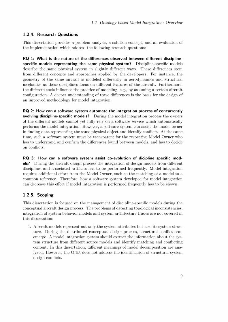
Internally, the Oida framework generates new artifacts and relations between them asdepicted in Figure 1.3 in a semiautuomated process witch involves the Match Models andMerge Models Partially use case. As model integration has to be performed more thenonce after periods of independent distributed modification of discipline-specific models,the Co-Evolve Integration Artifacts use case addresses the problem of co-evolution ofartifacts which are interrelated by the Oida framework. In the following, these threemain use cases are briefly described as well as the research questions and the scope ofthis dissertation which have led to the development of the Oida framework.
1.2.1. Match Models Use Case
A fundamental challenge of model integration is to identify abstract objects which repre-sent the same concrete object across different nomenclatures and decomposition strate-gies. As elaborated in Chapter 2 this challenge is addressed by a matching criterion thatis used to identify commonalities and differences between models. However, in order toensure that objects are interchangeable between different model contexts of conceptualdesign, a matching criterion has to be supplemented by user decisions. This interactivematching process is addressed by the Match Models use case. In this use case the modelsare not directly but indirectly matched via a common reference ontology. Correspondingto Gruber [Gru09], an ontology can be defined as follows
Definition 4 An ontology is a set of concepts of a certain domain, such as entities andrelations. An ontology formally defines the meaning and context of these concepts bylogical statements.
Ontologies are essential artifacts in all use cases of ontology-model integration. There-fore, Match Models involves not only the Model Owner but also the Ontology Owner whois responsible for ensuring especially the quality of the reference ontology. Both actorsare supported by a Reasoner, an external system which evaluates the logical statementsof ontologies in order to detect inconsistencies and infer new statements.
1In ancient Greek oÚda, oida means “I know”
7
1. Introduction
1.2.2. Merge Models Partially
The Match Models use case enables performance of the Merge Models Partially whicheffectuates the actual model integration. In contrast to the merge operation, model in-tegration only ensures that objects which represent the same entity are consistent. Un-matched content is only exchanged upon the demand of the respective Model Owner. Ac-cordingly, Merge Models Partially includes the Resolve Model Conflicts use case whereasMigrate Model Parts is optionally performed.
During the Resolve Model Conflicts use case Oida computes the differences betweenthe model Mi of the Model Owner and another discipline-specific model Mj which haveboth been matched before in Match Models. Mj is either a legacy model which hasbeen developed for a previous aircraft concept or is a model concurrently developed byanother Model Owner. The Model Owner cannot only decide to resolve the conflict byadopting the values of Mj but can also report an implausible matching to the OntologyOwner.
In the optional Migrate Model Parts use case the Model Owner can choose objects inMj to be migrated to Mi.
Definition 5 Model migration is the transfer of model parts from a source model to atarget model which have been selected by the Model Owner of the target model. If themetamodel of the source and the target model is not the same, model migration employsmodel transformation.
Definition 6 A model transformation translates objects conformal to a source meta-model MMi to objects in a target model Mj conformal to a target metamodel MMj.If both source and target metamodels are different in scope and level of abstraction, atransformation between them is not bijective.
Accordingly, the main challenge of the Merge Models Partially use case is to overcomethe heterogeneity of models which stems not only from different metamodels but alsofromS different and naming and decomposition conventions. The Oida framework real-izes this bridge by evaluating equivalence statements from the discipline-specific conceptsin Mi to the reference ontology.
1.2.3. Co-Evolve Integration Artifacts Use Case
In an aircraft design process the model data is distributed across different artifactscoupled by transformations. In the Co-Evolution the Oida framework facilitates theefficient propagation of changes in one artifact to other artifacts in order to maintainconsistency.
Ideally, a small change in one artifact requires only small changes in the other artifactscoupled to the changed artifact. The Oida framework is developed to increase the effi-ciency of change propagation by exploiting knowledge on small modifications which havebeen performed on the particular artifacts. Co-Evolution is important for the overallefficiency of a process imposed by a framework like Oida which introduces additionalartifacts, such as ontologies.
8
1.2. Ontology-based Model Integration: Overview
1.2.4. Research Questions
This dissertation provides a problem analysis, a solution concept, and an evaluation ofthe implementation which address the following research questions:
RQ 1: What is the nature of the differences observed between different discipline-specific models representing the same physical system? Discipline-specific modelsdescribe the same physical system in slightly different ways. These differences stemfrom different concepts and approaches applied by the developers. For instance, thegeometry of the same aircraft is modeled differently in aerodynamics and structuralmechanics as these disciplines focus on different features of the aircraft. Furthermore,the different tools influence the practice of modeling, e.g., by assuming a certain aircraftconfiguration. A deeper understanding of these differences is the basis for the design ofan improved methodology for model integration.
RQ 2: How can a software system automate the integration process of concurrentlyevolving discipline-specific models? During the model integration process the ownersof the different models cannot yet fully rely on a software service which automaticallyperforms the model integration. However, a software system can assist the model ownerin finding data representing the same physical object and identify conflicts. At the sametime, such a software system must be transparent for the respective Model Owner whohas to understand and confirm the differences found between models, and has to decideon conflicts.
RQ 3: How can a software system assist co-evolution of dicipline specific mod-els? During the aircraft design process the integration of design models from differentdisciplines and associated artifacts has to be performed frequently. Model integrationrequires additional effort from the Model Owner, such as the matching of a model to acommon reference. Therefore, how a software system developed for model integrationcan decrease this effort if model integration is performed frequently has to be shown.
1.2.5. Scoping
This dissertation is focused on the management of discipline-specific models during theconceptual aircraft design process. The problems of detecting topological inconsistencies,integration of system behavior models and system architecture trades are not covered inthis dissertation:
1. Aircraft models represent not only the system attributes but also its system struc-ture. During the distributed conceptual design process, structural conflicts canemerge. A model integration system should extract the information about the sys-tem structure from different source models and identify matching and conflictingcontent. In this dissertation, different meanings of model decomposition are ana-lyzed. However, the Oida does not address the identification of structural systemdesign conflicts.
9
1. Introduction
2. Product models represent not only the structural aspects of a product systembut also its behavior. A model of the system behavior is mostly relevant for theassessment of the operational performance of the product. However, behavioralaspects of the system are not taken into account.
3. One goal of conceptual aircraft design is to generate and assess feasible variants ofthe product’s system architecture. However, especially during the design of civilaircraft, the system architecture of the aircraft is fixed from the beginning. There-fore, this dissertation does not address the management of different architecturevariants.
This scope includes essential aspects of the current practice of conceptual aircraftdesign. In particular, the limitation to the structural model aspects of one aircraftarchitecture is a reasonable context for the development and evaluation of ontology-based model integration.
10
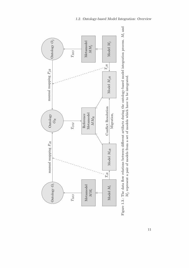
1.2. Ontology-based Model Integration: Overview
Ref
eren
ceM
etam
od
elM
MR
Onto
logy
OR
Mod
elM
iRM
od
elM
jRM
od
elM
i
Met
amod
elM
Mi
Onto
logy
Oi
Mod
elM
j
Met
amod
elM
Mj
Onto
logy
Oj
TM
O
TiR
manu
al
map
pin
gPiR
TM
O
TjR
man
ual
map
pin
gPjR
Con
flic
tR
esol
uti
on
Mig
rati
on,
TOM
Fig
ure
1.3
.:T
he
dat
afl
owre
lati
ons
bet
wee
nd
iffer
ent
arti
fact
sd
uri
ng
the
onto
logy
-bas
edm
od
elin
tegr
atio
np
roce
ss.M
ian
dM
jre
pre
sent
ap
air
ofm
od
els
from
ase
tof
mod
els
wh
ich
hav
eto
be
inte
grat
ed.
11
1. Introduction
1.3. Research Process and Outline
The current tool environments for conceptual aircraft design have been developed in atrade-off between flexibility to model new system architectures and components, andthe efficient management of consistency and exchange of models from different toolswhich requires adherence to constraining standards. This dissertation contributes to animprovement of these problems not by a substitution but by an extension of componentsof existing tools and practices. The basic idea of this dissertation is the mapping ofthe concrete problem of model integration to an abstract solution of ontology matching.However, the research process evaluates not only the effectivity of the Oida frameworkbut also efficiency of its application from the perspective of typical users which is a criticalcriterion for its applicability. Accordingly, this dissertation is structured as follows:
In Chapter 2 the fundamental terminology of the problem analysis and the descriptionof the solution is defined. In particular, concepts of equivalence and mereology areintroduced as well as the technological spaces of modeling and ontology.
Chapter 3 translates a concrete problem of concurrent model refinement during theconceptual design of aircraft to the abstract problem of model integration. Thereby,based on an analysis of sample models, the problem is defined by requirements andconstraints of the Oida framework. Additionally, this chapter gives an overview ofrelated work.
Chapter 4 describes the most important capabilities of the Oida use cases. These usecases are analyzed in Chapter 5 in order to identify participating objects and their rela-tions. The topic of Chapter 6 is the design of the Oida architecture and its components.
Chapter 7 evaluates whether the abstract solution of ontology-based model integrationtranslates back to the concrete context of conceptual aircraft design.
Chapter 8 summarizes the contributions of this dissertation and discusses topics forfuture work.
12
2. Terminology
In the following equivalence, mereology, and technological spaces are defined. The con-cept of equivalence between objects is introduced stepwise from the concept of identityto equality. Mereology defines kinds of part-whole relationships between entities. Bothconcepts are especially important for the analysis of the problem addressed in this disser-tation. The next section addresses especially the approach and the design of the Oida bydefining and comparing the terminology of modeling and ontology technological spaces.
2.1. Equivalence
Comparing two models regarding matching and distinctive content is an essential ca-pability of model integration as it enables identification of conflicts and content whichexists only in one model. This capability requires an operation determining whether twoobjects from different models represent the same physical object.
As an example consider two objects A and B from the models Mi and Mj . Bothmodels are stored at different locations and can be modified independently. Before it isdetermined whether A and B represent the same object, it has to be determined whetherA and B are actually identical.
Definition 7 The identity of an object comprises all its properties which distinguishesit from all other objects.
As an object can only be identical to itself, Dilworth [Dil88] discusses whether identityis actually a kind of relation. Practically, two objects are not identical iff at least onediscriminating property is measurable. In the following, we assume that neither Mi andMj nor A and B are identical as they have at least different names.
For complex objects it is usually impractical to determine identity. However, in aconcrete application it is usually sufficient to determine whether two objects are equalassuming an abstract object model.
Definition 8 Equality is a relation between two objects which can substitute for eachother assuming an object model which defines a subset of measurable properties I of anobject which are relevant for a certain purpose.
In the following we assume the object model proposed by Khoshafian and Copeland[KC86]. The properties of an object are attributes and references. An attribute has atype and a value. A reference is a link to another object. The references between aset of objects define a topology of the set which is a graph of objects which disregards
13
2. Terminology
the object attributes. In this object model the behavior of an object is disregarded.According to this object model, two objects can be substituted for each other if they aredeep-equal.
Definition 9 Two objects are deep-equal if their property values are identical, and re-cursively the property values of all referenced objects.
If all objects are globally unique, deep-equal objects are also shallow-equal
Definition 10 Two objects are shallow-equal if their property values are identical.
Shallow-equality between A and B is less complex to determine than deep-equalityas it does not require determination of the identity of property values of all referencedobjects recursively. Khoshafian and Copeland [KC86] argue that unique informationobjects do not necessarily change their identity if their property values or location aremodified. Therefore, they propose a more abstract object identity.
Definition 11 An object identity O is a subset of the object model which is globallyunique and independent of property values and location of the object.
Usually O is implemented as an immutable attribute value that is generated at thecreation of every object. If Mi and Mj are only discernible by their location, A and Bcan have identical O if Mi and Mj are always synchronized, which means that everymodification in Mi or Mj is propagated to the other model to ensure that objects withidentical O are deep-equal. Now assuming that Mi and Mj are not synchronized, A andB represent the same thing if they are a deep copy of each other.
Definition 12 Two objects are a deep copy of each other if they are deep-equal exceptregarding O of the two objects and the recursively referenced objects.
If A is a deep copy of B, both objects can represent unmodified local copies of anidentical ancestor object.
Definition 13 If A has been created by a deep copy of B, B is the ancestor object of A
Now it is given that A is not a deep copy of B but equivalent to it.
Definition 14 Equivalence is a relation between objects which can substitute for eachother in a certain context. An equivalence criterion defines a subset E of the object modelwhich can intersect with O. Equivalence between two objects can only be determined ifall properties in E can be measured in both objects. Two objects are equivalent if allproperty values in E are identical in both objects. If no property value in E is identical,the two objects are disjoint.
14
2.2. Mereology
The equivalence, equality, and identity are characterized as reflexive, transitive, andsymmetric relations. All these relations are reflexive because they always exist from anobject to itself. They are all transitive because if one of these relations exists betweenobject A and B, and between B and C, the relation always exists also between A and C.They are all reflexive because if one of these relations exists from A to B it always existsalso from B to A. However, these relation characteristics require a bijective mappingof all object properties, i.e. an identical object model. Assuming that Mi and Mj havebeen created for a different purpose and have a different object model, their objects canbe equivalent in a certain context but are not necessarily deep-equal. For instance, 2 and2.0 are equivalent in a context which disregards decimal digits. However, the exampleillustrates that a transitive and symmetric equality relation cannot be established forthese objects.
2.2. Mereology
Mereology , derived from ancient Greek mèroc meros “part” and lìgoc logos “word, ratio-nality”, is a discipline which analyzes and describes different kinds of part-whole relation-ships between objects. Mereology is relevant for model integration as aircraft designerstend to decompose their aircraft model according the the part-whole relationships of thephysical aircraft. Thereby, aircraft designers use modeling language constructs whichrepresent containment relations. For instance, UML defines the composition associationwhich is a directed relation between two objects. One object can have a compositionrelation to more than one object but every object can only be contained in one object.If object A is related to B by a composition, B is contained in A. B is destroyed if A isdestroyed.
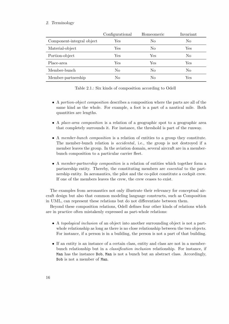
However, containment relations between objects have more differentiated properties.Winston et al. [WCH87] propose a taxonomy of six different kinds of containment whichare discriminated by the three properties configurational, homeomeric and invariant.A containment is configurational if it relates objects that have a specific functional orstructural relationship to one another or to the object they constitute. A containmentrelation is homeomeric if the parts are of the same kind as the whole. A containmentrelation is invariant if the parts can be separated from the whole. Odell [Ode94] adoptsthese criteria, but proposes a slightly different taxonomy of the following six kinds ofcomposition (see Table 2.1):
• A component-integral object composition is a relationship between an entity andits constituting entities. This part-whole relationship can be tangible, abstract ororganizational. For example, an engine blade is an integral part of a turbo engine.In contrast to Winston et al., Odell states that if two objects are separated theycan no longer have this kind of relation.
• A material-object composition interrelates an entity to materials “the entity ismade of”, e.g., the Boeing B 747 aircraft primary structure is made of aluminium.
15
2. Terminology
Configurational Homeomeric Invariant
Component-integral object Yes No No
Material-object Yes No Yes
Portion-object Yes Yes No
Place-area Yes Yes Yes
Member-bunch No No No
Member-partnership No No Yes
Table 2.1.: Six kinds of composition according to Odell
• A portion-object composition describes a composition where the parts are all of thesame kind as the whole. For example, a foot is a part of a nautical mile. Bothquantities are lengths.
• A place-area composition is a relation of a geographic spot to a geographic areathat completely surrounds it. For instance, the threshold is part of the runway.
• A member-bunch composition is a relation of entities to a group they constitute.The member-bunch relation is accidental , i.e., the group is not destroyed if amember leaves the group. In the aviation domain, several aircraft are in a member-bunch composition to a particular carrier fleet.
• A member-partnership composition is a relation of entities which together form apartnership entity. Thereby, the constituting members are essential to the part-nership entity. In aeronautics, the pilot and the co-pilot constitute a cockpit crew.If one of the members leaves the crew, the crew ceases to exist.
The examples from aeronautics not only illustrate their relevancy for conceptual air-craft design but also that common modeling language constructs, such as Compositionin UML, can represent these relations but do not differentiate between them.
Beyond these composition relations, Odell defines four other kinds of relations whichare in practice often mistakenly expressed as part-whole relations:
• A topological inclusion of an object into another surrounding object is not a part-whole relationship as long as there is no close relationship between the two objects.For instance, if a person is in a building, the person is not a part of that building.
• If an entity is an instance of a certain class, entity and class are not in a member-bunch relationship but in a classification inclusion relationship. For instance, ifMan has the instance Bob, Man is not a bunch but an abstract class. Accordingly,Bob is not a member of Man.
16
2.3. Technological Spaces
• An attribution is the relation of an entity to its attributes. By this relation,attributes are associated with an entity but are not components of it, e.g., if a boxis red, the color red is not a part of the box.
• An attachment is a relation between linked objects. Linked objects are not neces-sarily in a part-whole relationship. For example, a lid on a pot is connected andhas a functional relationship to the pot but is not part of it.
• Ownership is a relation from one entity to another entity which it possesses. If anentity A owns entity B, it does not mean that B is part of A, e.g., if Alice owns adog, the dog is not part of her.
The occurrence of these pseudo-containment relations is an important symptom ofmodels which represent the same system but with a different decomposition strategy.
2.3. Technological Spaces
According to Kurtev et al. [KBA02] a technological space (TS) is a combination ofmethodologies and tools, which are learned, applied, and further developed by a com-munity of persons. In contrast to disciplines, the technological space concept emphasizesa degree of self sufficiency which allows its members to solve a problem within its bound-aries. Basically, the Oida framework establishes a mapping between the Modeling TSand the Ontology TS . By this mapping the problem of model integration is transformedto a problem of ontology integration. The problem is solved in the Ontology TS andpropagated back to the Modeling TS. In the following, both technological spaces arebriefly described by defining some of their fundamental concepts.
Concepts of the Modeling Technological Space
The Modeling Technological Space (Modeling TS) is a working environment realizing theModel Driven Architecture (MDA) proposed by the Object Management Group (OMG)[Mel+02]. The artifacts of this technological space are models and metamodels. MDAalso stipulates transformations between Platform Dependent Models (PDMs) and Plat-form Independent Models (PIMs). The basic idea of MDA is to improve the efficiency ofdeveloping and maintaining systems by making changes on platform-independent mod-els (PIM) and to generate platform-dependent models (PDM) by these transformations.An important framework of the MDA is the Meta Object Facility (MOF ) [Gro11] whichproposes a framework of four layers of abstraction.
The M0 layer contains objects from the real world . A set of these objects is a system.For instance, physical systems and a running software system exist at the M0 level.
The M1 layer contain objects which are abstract representations of the state andbehavior of real world objects and their relations on the M0 level. A set of these objectsis a model of a system. For instance, the software source code is a model of a runningprogram.
17
2. Terminology
Objects on the M2 layer are abstract specifications of properties and operations ofobjects and relations at the M1 level. A set of these objects is a metamodel. Objectsin a model are instances of objects in a metamodel. Thereby, a metamodel can specifya formal language. For instance, the Unified Modeling Language (UML) [OMG11] isspecified on the M2 layer.
Objects on the M3 layer are an abstract specification of objects and relations at theM2 layer. A set of these objects is called a meta-metamodel. For instance, MOF is onthe M3 layer. MOF is not only the metamodel of UML on the M2 layer but definesalso its own metamodel by the fundamental concepts classifier, instance, and reflection.The latter enables the navigation between classifier and instance objects.
The object model specified by the common classifier of an object can be used asan equivalence criterion as the instanceOf relation ensures that these properties aremeasurable in both objects.
Abstraction has the consequence that an identical real object can be represented byobjects with a non-identical set of properties. For example, if two have been createdfrom two different metamodels or the same metamodel has been interpreted differently,two objects representing the same real entity can only be determined by matching.
Definition 15 A match is a relation between objects that are not necessarily equivalentbut represent the same object. The relation is determined by a matching criterion whichdefines a subset S of properties in an equivalence criterion E. Two objects do not matchif at least one property which is measurable in both objects is not identical.
In contrast to equivalence, the match relation is reflexive but not transitive and sym-metric. Two matching objects cannot substitute for each other if they are not equivalent.Given that two objects match each other, e.g., (name: wingspan, measure: 3; unit: m)matches (name: span; measure: 3), substituting span for wingspan would reduce infor-mation in the name and unit attribute.
A common matching criterion is a common ancestor object. This equivalence criteriondetermines equivalence between local copies, which have been modified independently.However, to determine a match between two objects if they were created independentlyor if the ancestor object is not measurable, an equivalence criterion must define necessaryand sufficient conditions specific for a concrete application.
If object A and B match but are not equivalent they are in conflict.
Definition 16 Conflict is a relation which can only exist between matching objects. Aconflict criterion C is the relative complement of S in E. If at least one property in Cis not identical, the equivalent objects are in conflict.
Now given that A and B are in conflict, the conflict can be resolved.
Definition 17 A conflict between two equivalent objects is resolved by modifying everyproperty in C to an identical value.
18
2.3. Technological Spaces
Usually a conflict is resolved by copying all values from one of the objects to the other.After a conflict resolution two matched objects are equivalent in a certain context. How-ever, the two objects are only equal if they have the same classifier which is fully coveredby E and C. All possible classifiers of a model are defined in its metamodel. Therefore,equality between two models can only be ensured if they have an equal metamodel.
Concepts of the Ontology Technological Space
The Ontology Technological Space (Ontology TS) is a combination of methods and toolsfor knowledge representation and automated reasoning. In particular, an ontology lan-guage is used to represent the knowledge in an ontology.
The term ontology is derived from the ancient Greek words eÊmÐ eimi “I am” and lìgoc
logos “word, rationality”. In philosophy it means the study of “being” entities and theirstructure. In the domain of computer science “[. . . ] an ontology defines a set of repre-sentational primitives with which to model a domain of knowledge or discourse”[Gru09].Accordingly, an ontology defines entities and relations between these entities which areconstrained by logical statements. Thereby, the semantics of the entities can be for-mally defined. The intended application of an ontology is an important feature. Forinstance, the primary application of the reference ontology in this dissertation is toprovide a representation of knowledge in the domain of conceptual aircraft design. Amachine-readable ontology representation can be used for automated reasoning. Thebasic functionality of an automated reasoner is the classification of entities. Thereby, areasoner not only determines the consistency of statements in an ontology but can alsoinfer new statements.
Ontologies can be connected to each other in a hierarchy. For example, an ontologycontaining application-specific concepts can import another ontology containing moregeneral concepts and use it as an upper ontology [Sch03].
Definition 18 An upper ontology comprises abstract and generic concepts which can beshared across domains, such as mereology or physical measures.
Ontologies can be designed with the help of tools or derived from natural language or ex-isting models. An ontology language can express semantic relation by logical statementswhich can be evaluated by a reasoner.
Model vs. Ontology
Models and ontologies both deal with the representation of physical and virtual concepts.However, models and ontologies are generally used with different intentions [Hen11].Models are prescriptive representations which are usually based on the closed worldand unique name assumption, which makes them more adept for systems design andimplementation. In contrast, ontologies are descriptive representations which are usuallyfounded on the open world assumption. For example, a model and an ontology representthe facts that every person can only have one mother and that there are two personsBob and Bob’s mother Peggy. Both model and ontology can be queried as to whether
19
2. Terminology
Margret is Bob’s mother. According to the closed world assumption, the answer for themodel is “No”, because the model does not contain an explicit statement that Margretand Peggy are the same person. In contrast, according to the open world assumption, theresult of the query to the ontology is ”Unknown”, because there is no explicit statementthat Peggy and Margret are not the same person. Now the fact that Margret is Bob’smother is added to both model and ontology. Based on the unique name assumption themodel would become invalid, as Bob cannot have two mothers. As the ontology does notassume unique names for entities, the ontology does not become invalid. Additionally,an automated reasoner can evaluate the ontology and infer that Margret and Peggy arethe same person. In this example, the ontology is not only more robust than the modeldealing with different perspectives to the same object but has derived new knowledge.
Ontologies represent concepts by entities and properties. Entities are classes andindividuals who are instances of classes. Properties are relations from entities to otherentities or to data types. In contrast to modeling languages, ontology languages allowdeclaration of an equivalence relation between concepts by an equivalence statement. Forinstance, an equivalence statement between two individuals (name: wingspan; measure:3; unit: m) and (name: span; measure: 3) has the effect that both objects are treatedas (name: wingspan, span; measure: 3; unit: m). Accordingly, the conflict resolutionand the declaration of equivalence between two matched objects leads to equal conceptseven if the concepts have a different set of properties.
20
3. Problem Definition and Related Work
The problem context addressed in this dissertation is the conceptual aircraft designphase which is software intensive as it has to rely predominantly on virtual productmodels. The different levels of abstraction and the flexibility of modeling languagesallow different naming and decomposition conventions, which inhibits efficient matchingobjects between different models. However, despite the abstraction of design models theirintegration is based on the assumption that design models represent the same physicalobject. Therefore, the following chapter gives an analysis of differences between samplemodels from conceptual aircraft design. Based on these observations, the problem isdefined by stating the requirements and constraints of the Oida which is put into thecontext of related work already performed by other researchers.
3.1. Sample Models
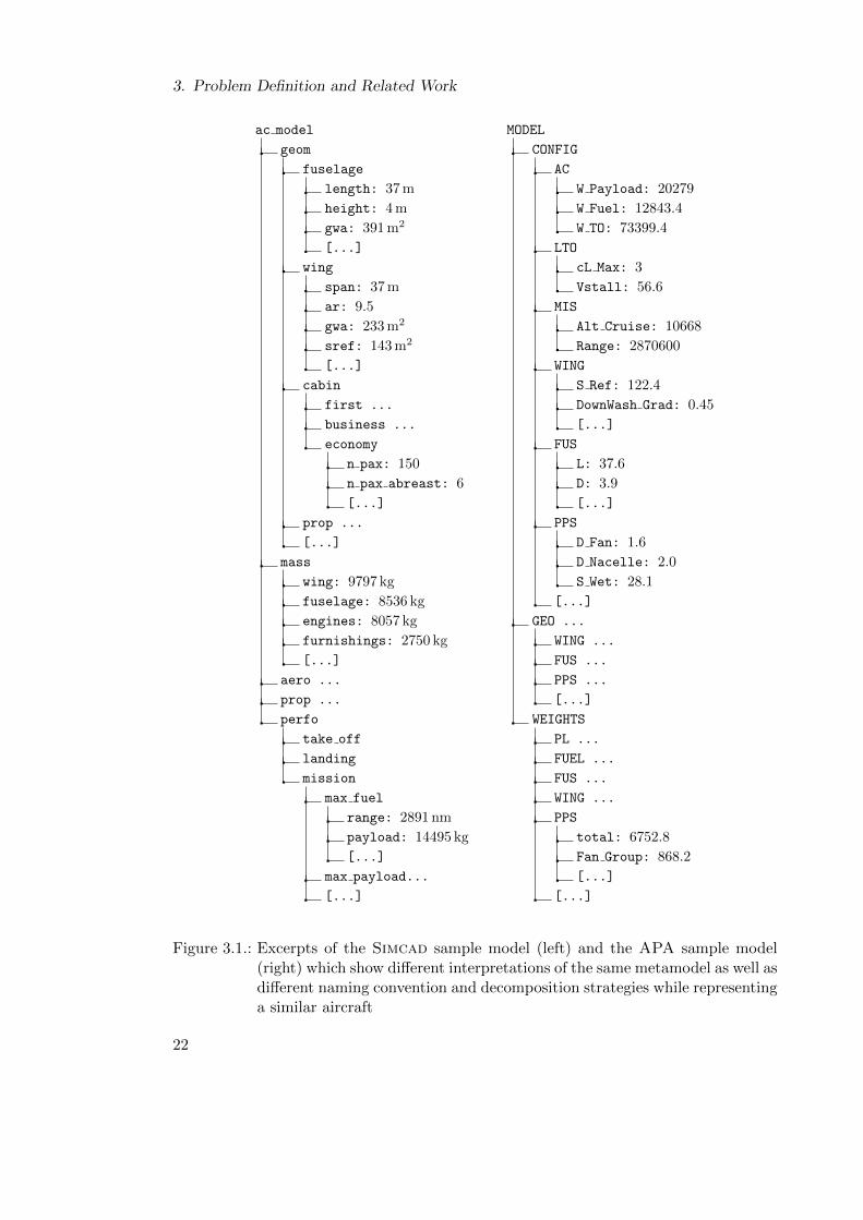
The concept of ontology-based model integration was developed and evaluated usingthree sample models from different tools called Simcad, APA, and APD.
These tools were chosen as they cover a variety of typical data models in aircraftconceptual design with respect to scope, complexity, and focus. Although they aregenerally not used concurrently in the same project, they describe structural aspects ofthe same type of aircraft. Therefore, they can be used to simulate the situation whenthree models of the same aircraft are generated by independent design groups.
Simcad is a tool which has been developed at the Airbus Future Projects Officefor conceptual aircraft design studies. It is basically a collection of scripts executableon the Scilab platform. Scilab is an open source numerical calculation environmentsimilar to Matlab. Simcad employs two types of internal data exchange: (1) theprocessing blocks passing data via function parameters and (2) the processing blocksmanipulating data on a globally accessible data structure like reading from and writingon a black board. The black board is a data structure which is used as a global look-uptree for aircraft design algorithms, such as weight and performance estimation. Withinthe black board the naming convention for variables is widely comprehensible for anyaircraft design expert. A special Simcad script serializes the black board using a specificsyntax. The script not only encodes the treelike data structure but specifies units forevery scalar value. As the black board data structure mostly contained structural aspectsof the aircraft was used as the Simcad sample model.
The Advanced Propulsion Analysis tool (APA) has been developed at Bauhaus Luft-fahrt based on Matlab. It was originally developed by Seitz [Sei12] to compare the
21
3. Problem Definition and Related Work
ac model
geom
fuselage
length: 37 m
height: 4 m
gwa: 391 m2
[...]
wing
span: 37 m
ar: 9.5
gwa: 233 m2
sref: 143 m2
[...]
cabin
first ...
business ...
economy
n pax: 150
n pax abreast: 6
[...]
prop ...
[...]
mass
wing: 9797 kg
fuselage: 8536 kg
engines: 8057 kg
furnishings: 2750 kg
[...]
aero ...
prop ...
perfo
take off
landing
mission
max fuel
range: 2891 nm
payload: 14495 kg
[...]
max payload...
[...]
MODEL
CONFIG
AC
W Payload: 20279
W Fuel: 12843.4
W TO: 73399.4
LTO
cL Max: 3
Vstall: 56.6
MIS
Alt Cruise: 10668
Range: 2870600
WING
S Ref: 122.4
DownWash Grad: 0.45
[...]
FUS
L: 37.6
D: 3.9
[...]
PPS
D Fan: 1.6
D Nacelle: 2.0
S Wet: 28.1
[...]
GEO ...
WING ...
FUS ...
PPS ...
[...]
WEIGHTS
PL ...
FUEL ...
FUS ...
WING ...
PPS
total: 6752.8
Fan Group: 868.2
[...]
[...]
Figure 3.1.: Excerpts of the Simcad sample model (left) and the APA sample model(right) which show different interpretations of the same metamodel as well asdifferent naming convention and decomposition strategies while representinga similar aircraft
22
3.1. Sample Models
“Open Rotor” versus the “Ducted Geared Turbo Fan” propulsion concepts on a com-mon basis. Accordingly, the structural aspect of the model covers the overall aircraftbut is focused on propulsion-related aspects of the system. APA employs a centraldata structure representing aircraft system attributes, which are used by the calculationscripts both as data source and target. In accordance with common practice of mod-eling in Matlab, the units of measure for each attribute are not specified in the datastructure. Instead, a Matlab script responsible for serialization of this data structurecontains a unit specification and short description of each value as comment. The nam-ing convention of variables in APA is mostly oriented to symbols commonly used inaircraft design literature. However, without the comments in a separate script file, thenomenclature is difficult to comprehend. The central data structure contains a consid-erable amount of data which do not define structural aspects of the aircraft, and thusare beyond the scope of this dissertation, e.g., the results of mission simulations whichrather describe the behavior of the system. However, the model objects associated withthese aspects are arranged in subtrees of the model which could be clearly separated.The remaining APA central data structure was exported to a file and used as the APAsample model.
The Pace Lab Suite is a commercial tool developed by Pace Lab for conceptualaircraft design. Pace Lab offers the Aircraft Preliminary Design (APD) plug-inwhich provides a collection of implemented common preliminary aircraft design methodsand models of recent civil transport aircraft, such as the Airbus A320. These aircraftmodels are used to benchmark new aircraft concepts or calibrate new performance es-timation methods. Generally, the models cover the overall aircraft and have no focuson a specific subsystem. The aircraft model parameters can be serialized to a commaseparated values (CSV) file. Each entry in the CSV file contains the name of the parentobject representing the hierarchical model structure. Entries representing scalar valuesadditionally specify the respective unit of measure. The APD parameters also containdata which describe the system behavior. For instance, there are data tables on the spe-cific fuel consumption (SFC) of the engine in different system states. The identificationof equivalent state variables like SFC requires not only matching of their dependencies tosystem states but also interdependencies among system states. However, the integrationof system states, which are part of the behavioral model of an aircraft system, is notaddressed in this dissertation. Therefore, SFC tables were removed early from the CSVfile by filtering representations of scalar values. The result was used as the APD samplemodel.
The similar structure of the tool data models allows the transformation a tool spe-cific format to a common metamodel. For this conversion, the tool connectors of theConceptual Design Tool (OpenCDT) [ZGS11] were used which transfer the variablenames and the data structure of the original models directly to MOF-compliant Javaobject models. Using this representation, the following comparative observations couldbe made:
• The sample models exhibit considerable semantic overlap. As a consequence, el-ements from different source models represent the same physical object. Under
23
3. Problem Definition and Related Work
the assumption that the models represent the same aircraft, these overlaps are apotential source of inconsistencies.
• The sample models contain attributes which characterize the modeled aircraft.These characteristics either explicitly describe the system topology , e.g., the num-ber of windows, or describe measurable attributes of system components. Theycan be scalar, or be represented in more complex structures, such as vectors, ortensors. Only the Simcad and the APD sample model explicitly state units ofmeasure.
• All sample models use the object composition association for different decompo-sition strategies. In the Simcad model, for instance, it can be observed, thatthe containment relation is used for three different kinds of decomposition. Thereis a geometry tree representing a component-integral object decomposition. Themass container represents classification inclusion decomposition. The take-off
container represents a decomposition oriented to an attribution relation to systemstates. Only the geom container and its child objects have a component-integralobject relation which can be classified as containment. The APD model shows thesame types of decomposition. The APA consistently uses classification inclusionrelations at the first tree level and an attribution relation in the second layer. Itcan be concluded that the decomposition strategy of all sample models is rather de-signed more towards efficient access to data entries during the numeric calculationprocesses within the respective tool than towards data exchange.
• Generally, the name attribute of a model element indicates the physical entity itrepresents. However, this naming convention is not standardized. Especially, inAPA the objects are named by abbreviations which are difficult to comprehendwithout further documentation outside the model.
3.2. Oida Requirements and Constraints
Based on the analysis of the sample models, the Oida framework has been developedaccording to the following top-level requirements:
• The entities of all models must be matched with a common reference ontology.Model elements representing data specific to tools or disciplines can be deliber-ately excluded from the integration process by the model owner. Furthermore,model parts representing non-structural aspects of the aircraft as well as non-scalarattribute values are generally excluded from the mapping process.
• The Oida framework must facilitate the detection and resolution of conflicts be-tween equivalent model elements from different sample models. Thereby, one ofthe models is declared to be the Chief Engineering Model which overrules theother models in the case of conflict. This scenario assumes that a chief engineer isentitled to propagate his design decisions to the other models.
24
3.2. Oida Requirements and Constraints
• The Oida framework must give Model Owners an essential role in the ontology-based model integration. In particular, Model Owners must perceive the processof ontology-based model integration as efficient and the result as plausible fromthe aircraft design expert point of view.
• Repeated performance of the model integration process with small changes in thesource models, the reference ontology, or the integration related algorithms mustrequire only small changes on the other coupled artifacts to maintain overall con-sistency.
The following design constraints have been posed early in the development process inorder to foster a simple but meaningful and extensible proof-of-concept:
Reference Ontology It was decided to use an ontology as a common reference forthe integration of discipline-specific models. A classification of technical approaches tomodel integration was described by Noy [Noy04]. She discriminated between ontology-based integration and heuristics-based integration techniques. The latter are commonlyused in database schema integration and are based on lexical and structural analysis ofthe given models. In contrast to these techniques, ontology-based approaches exploitthe semantics of relationships between entities. Generally, not only ontology languagesbut also modeling languages allow defining and constraining entities and links. For in-stance, UML defines relationships like Generalization, Composition, and Attribute,which can be constrained by OCL. However, the semantics of these relationships are notformally specified. In contrast, an ontology language, such as OWL, can express formalsemantics by description logic [BHS08] which can be interpreted by automated reasoners.The resultant reference ontology can potentially be reused in other application contexts.
Simple Equivalence Another early decision was to realize the matching of discipline-specific models exclusively by equivalence statements between ontologies. Weaker nu-ances of equivalence would allow the domain expert to adequately express relation be-tween similar concepts. However, these nuances of equivalence are not defined in stan-dard ontology languages. Furthermore, application of similarity relations during MatchModels requires a shared understanding of similarity among all Model Owners whichwould add organizational complexity. Therefore, Oida only uses equivalence relations.This constraint also limits the complexity of the ontology, as the Model Owners onlyadd an equivalence relation between two concepts if they consider them to represent thesame object. Furthermore, the limitation on standardized simple equivalence facilitatesthe development and evaluation of ontology processing capabilities as these relationshipsare well supported by existing ontology frameworks and reasoners.
Simple Part-whole Relationship As described in Section 2.2 mereology is an importantfeature of physical systems and the models representing them. Therefore, a simplemereology upper ontology is provided as a common basis for both the reference ontologyand ontology-based transformation algorithms. The mereology upper ontology defines
25
3. Problem Definition and Related Work
the transitive properties isPartOf and its opposite hasPart as well as the correspondingsubproperties isPartOf directly and hasPart directly. The reference ontology usesthese properties as a generic foundation of a component-integral object relation, whereasthe ontology-based transformation algorithms asserts the hasPart directly propertyas a formal representation for the composition association of UML. The detailed designof the mereology upper ontology and its application in the reference ontology is providedin Appendix B.
3.3. Related Work
The application of ontologies for the integration in conceptual aircraft models is basedon work already conducted by other researchers who have already successfully appliedthe consolidation and transformation of models from different sources. However, theirapproaches do not address the level of heterogeneity and domain specificity pursued inthis dissertation.
3.3.1. Tool and Model Integration
Kramler et al. [Kra+06] describe the idea of a semantic infrastructure for tool integration.The metamodels of tools are “lifted” to so called tool ontologies, i.e. the metamodelelements are mapped to ontologies which contain tool-specific concepts. These toolontologies are “bound” to a generic ontology, i.e. the tool specific concepts are mappedto generic concepts. To give an example from business process modeling, the conceptAction from UML and Activity from BPEL can be bound to the generic concept ofProcessStep. The resulting bindings are used to generate model transformations whichallow transformation of models from one tool to another. This infrastructure is similarto the Oida framework. However, analysis of the sample models revealed that the gapbetween the abstraction levels of the metamodels and the instance models allowed toomuch ambiguity of the object model regarding its meaning and relation to other modelelements. Thus, mapping on the metamodel level proposed by Kramler et al. [Kra+06]is not sufficient for the reliable determination of overlaps between the sample models.
Maalej [Maa10] uses ontologies as an essential component of his solution for toolintegration. While his work focuses on seamless work flow integration, his descriptionof specific features of ontologies as enabling technology also applies to the integrationof design models. Therefore, his considerations also motivated the design decision todevelop an ontology-based approach for model integration.
Del Fabro and Valduriez [DFV07] claim that the efficient generation of model trans-formation is a key technology for efficient model integration. The authors describe theautomated generation of a weaving model which contains a structured mapping betweentwo metamodels. For instance, given two metamodels from business process modellingthe waving model would contain a mapping object between the classes ActionItem andTask. This mapping object would further contain mapping objects between the respec-tive attributes and associations of these classes. The automated generator of such aweaving model identifies synonym relationships between metamodel entities by queries
26
3.3. Related Work
to the WordNet ontology [Fel10]. However, their solution is only based on metamodelmatching, and does not evaluate meaning or context of instance model elements. Fur-thermore, the solution does not address the situation when WordNet does not containa concept, a situation which is likely in conceptual aircraft design. In contrast, Oidaallows addition of new concepts to the reference ontology during the Match Models usecase.
Simon Zayas et al. [SZMA11] apply model matching via a reference representation ofthe product system model. This reference representation is not realized by an ontologybut by a model which is separately created in one of the tools. This reference modelallows matching of models from different tools representing different developmental as-pects to the same avionics system. However, the reference model strongly depends ona specific tool and development domain which limits its reuse in another applicationcontext. Furthermore, the language of the reference model does not have the expressiv-ity of an ontology language regarding semantics and cannot be directly processed by areasoner. For this reason, as discussed in Section 3.2, the Oida uses an OWL ontologyas common reference for integration.
Roser [Ros08] realizes ontology-based model transformation by employing differentnuances of equivalence, such as similarity and overlap, for the matching of metamodelelements, as well as OWL and an automated reasoner in order to facilitate the matchingof the metamodel concepts. The transformation is generated using the indirect matchingsof target and source metamodels of the transformation via a reference ontology. Oidaalso uses a reference ontology to realize model transformation and matching. The genericdata format of sample models allowed a simple transformation of the sample models tothe same metamodel using the tool connector capability of OpenCDT. Therefore, theOida framework addresses the problem of matching different interpretations of the samegeneric metamodel, which manifests in different naming and decomposition conventionsof the sample models. Furthermore, in contrast to Roser’s solution which is fully auto-mated, the Oida engages the Model Owners in an interactive process. Thereby, ModelOwners not only control the process, but also report errors of automated matchingalgorithms and extend the reference ontology in the process
Different types of model integration approaches are categorized regarding organiza-tional effort by Jardim-Goncalves et al. [JAS10] by estimating the time required forcommunication between organizations. They discriminate between slack, unregulated,standard-based, semantic interoperability, and sustainable interoperability. Accordingly,the Oida framework is a semantic interoperability type approach which is more efficientthan standard-based interoperability approach, e.g., CPACS or SysML, if the mappingof the model data to a common ontology is faster than solving data clarification issuesfor each model exchange by experts. Therefore, in order to support the assessmentontology-based model integration, the evaluation in Chapter 7 investigates the efficiencyperceived by Model Owners during the Match Models case studies and the measurableefficiency in Co-Evolve Integration Artifacts quasi-experiments.
27
3. Problem Definition and Related Work
3.3.2. Ontology Generation and Matching
Gasevic et al. [Gas+04] aim at a seamless integration of ontology tools with UML-basedmodeling tools. They present a transformation from the Ontology Definition MetamodelSpecification (ODM) [Obj09] to OWL, based on the eXtensible Stylesheet LanguageTransformation (XSLT). The mapping between UML and OWL which is defined in theannex of the ODM specification served as a template for the model-to-ontology andontology-to-model transformations of Oida. However, Oida is not designed to providean ontology-based aircraft modeling tool but to facilitate the integration of existingaircraft models employing ontology-based technologies. Therefore, Oida uses separatespecialized frameworks for handling models and ontologies, respectively.
Halpin and Hayes [HH10] describe the history of the concept identity and the conse-quences of a sameAs relation between concepts from different ontologies. The authorsargue that this kind of equivalence relation is a strong statement and should be usedcarefully in distributed information systems, such as the semantic web. Their recommen-dation opposes the constraint stated in Section 3.2 that the Oida framework only usessimple equivalence relations. However, the sample models are significantly less complexthan the semantic web. Furthermore, the Match Models use case stipulates the OntologyOwner who can advise the Model Owner to declare an equivalence relation in undoubtedcases.
Doan et al. [Doa+03] propose a schema-matching algorithm GLUE which uses a setof “learning strategies” for finding the best match between schema items. “Learning” inthis context means that an algorithm uses a given structure to generate good propositionsfor schema matching. The learning strategies used by Doan et al. are comparable withthe concept of EquivalenceFinders in Oida described in Chapter 6. For instance,the “content finder” corresponds to the StructuralEquivalenceFinder, the “namelearner” corresponds to the NameEquivalenceFinder but also takes the containers ofthe respective entity into account. The capability of a “meta-learner”, which is basicallyan aggregation of the aforementioned strategies by a weighted sum, is realized in theOida by a Blackboard pattern. GLUE supports complex mappings between ontologyentities. For instance, the entity name in one ontology can be related to two entitiesfirstName and lastName. In contrast to GLUE, Oida’s ontology-matching processdoes not require complex mappings during Match Models as the tool connectors ofOpenCDT transform the sample models to a common metamodel.
3.3.3. Evolution of Coupled Artifacts
Herrmannsdoerfer et al. [HBJ09] address the problem of co-evolution of metamodelsand their model instances by the EMF Edapt framework. EMF Edapt is based onrecording the user’s modifications to a metamodel which are put into the context of aspecified refactoring which the user intends to apply. After certain types of refactoringsto a metamodel have been recorded, the framework generates a transformation scriptwhich migrates existing instance models of the old version of the metamodel to thenew version of the metamodel [HVW11]. The idea of the EMF Edapt framework to
28
3.3. Related Work
evaluate known modification to artifacts in order to facilitate the co-evolution of coupledartifacts has inspired the design of the Oida evolution capabilities. In particular, theOida framework provides a prototypical support for a rename refactoring in the referenceontology.
Kogel [Kog11] shows that a system performs significantly better than a text-basedmodel version control process. EMFStore, an implementation of operation-based ver-sion control, uses recorded change operations on local copies of the model under versioncontrol. As change operations reference the metamodel, the conflict detection and con-flict resolution recommendations to the user are more specific to the domain contextof the user as compared to a text-based version control system, which are agnostic tothe metamodel. The software algorithm for conflict detection in Oida is not operation-based as changes to the discipline-specific models are performed outside of the systemboundaries of the Oida framework.
29

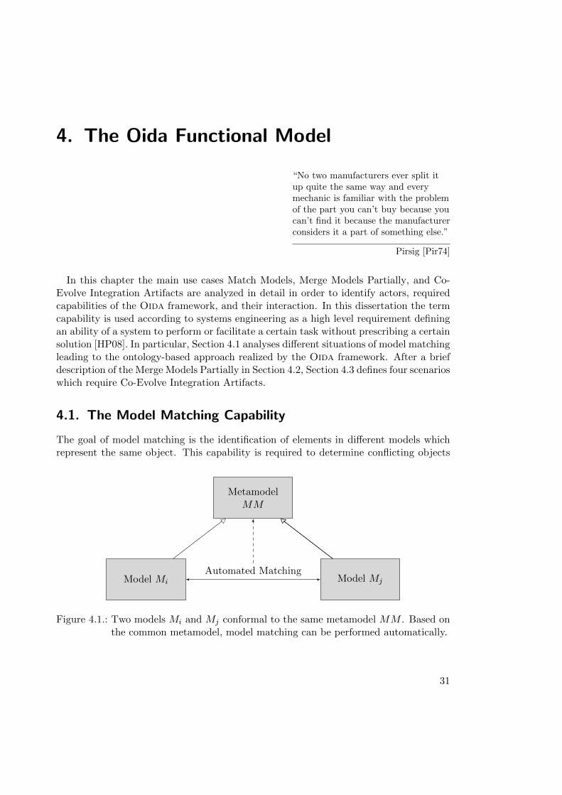
4. The Oida Functional Model
“No two manufacturers ever split itup quite the same way and everymechanic is familiar with the problemof the part you can’t buy because youcan’t find it because the manufacturerconsiders it a part of something else.”
Pirsig [Pir74]
In this chapter the main use cases Match Models, Merge Models Partially, and Co-Evolve Integration Artifacts are analyzed in detail in order to identify actors, requiredcapabilities of the Oida framework, and their interaction. In this dissertation the termcapability is used according to systems engineering as a high level requirement definingan ability of a system to perform or facilitate a certain task without prescribing a certainsolution [HP08]. In particular, Section 4.1 analyses different situations of model matchingleading to the ontology-based approach realized by the Oida framework. After a briefdescription of the Merge Models Partially in Section 4.2, Section 4.3 defines four scenarioswhich require Co-Evolve Integration Artifacts.
4.1. The Model Matching Capability
The goal of model matching is the identification of elements in different models whichrepresent the same object. This capability is required to determine conflicting objects
MetamodelMM
Model Mi Model MjAutomated Matching
Figure 4.1.: Two models Mi and Mj conformal to the same metamodel MM . Based onthe common metamodel, model matching can be performed automatically.
31
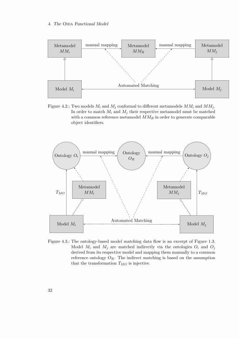
4. The Oida Functional Model
MetamodelMMR
MetamodelMMi
MetamodelMMj
Model Mi Model Mj
manual mapping manual mapping
Automated Matching
Figure 4.2.: Two models Mi and Mj conformal to different metamodels MMi and MMj .In order to match Mi and Mj their respective metamodel must be matchedwith a common reference metamodel MMR in order to generate comparableobject identifiers.
OntologyOR
Ontology Oi
MetamodelMMi
Model Mi
Ontology Oj
MetamodelMMj
Model Mj
TMO
manual mapping
TMO
manual mapping
Automated Matching
Figure 4.3.: The ontology-based model matching data flow is an excerpt of Figure 1.3.Model Mi and Mj are matched indirectly via the ontologies Oi and Oj
derived from its respective model and mapping them manually to a commonreference ontology OR. The indirect matching is based on the assumptionthat the transformation TMO is injective.
32
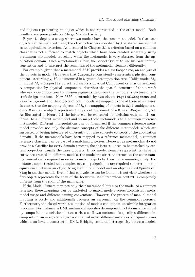
4.1. The Model Matching Capability
and objects representing an object which is not represented in the other model. Bothresults are a prerequisite for Merge Models Partially.
Figure 4.1 depicts a setup where two models have the same metamodel. In that caseobjects can be matched using the object classifiers specified by the shared metamodelas an equivalence criterion. As discussed in Chapter 2.1 a criterion based on a commonclassifier is not sufficient to match objects which have been created separately usinga common metamodel, especially when the metamodel is very abstract from the ap-plication domain. Such a metamodel allows the Model Owner to use his own namingconvention and to interpret the semantics of the metamodel elements differently.
For example, given that a metamodel MM provides a class Composite, an analysis ofthe objects in model Mi reveals that Composite consistently represents a physical com-ponent. Accordingly, Mi is structured in a system decomposition tree. Unlike model Mi,in model Mj a Composite object represents a physical Component or mission segment.A composition by physical components describes the spatial structure of the aircraftwhereas a decomposition by mission segments describes the temporal structure of air-craft design missions. Now MM is extended by two classes PhysicalComponent andMissionSegment and the objects of both models are mapped to one of these new classes.In contrast to the mapping objects of Mi, the mapping of objects in Mj is ambiguous asevery Composite object represents a PhysicalComponent or a MissionSegment object.As illustrated in Figure 4.2 the latter can be expressed by declaring each model con-formal to a different metamodel and to map these metamodels to a common referencemetamodel. Different interpretations can be formalized if the common reference meta-model provides not only the abstract concepts of the different metamodels which aresuspected of beeing interpreted differently but also concrete concepts of the applicationdomain. If the metamodels have been mapped to a reference metamodel, a commonreference classifier can be part of a matching criterion. However, as metamodels do notprovide a classifier for every domain concept, the objects still need to be matched by cer-tain properties, usually the name property. If two model elements representing the sameentity are created in different models, the modeler’s strict adherence to the same nam-ing convention is required in order to match objects by their name unambiguously. Forinstance, sophisticated and complex matching algorithms are required to determine theequivalence between an object WingSpan in one model and an object called SpanMain-
Wing in another model. Even if that equivalence can be found, it is not clear whether thefirst object represents the span of the horizontal stabilizer whose context is completelydifferent from the span of the main wing.
If the Model Owners map not only their metamodel but also the model to a commonreference these mappings can be exploited to match models across inconsistent meta-model usage and different naming conventions. However, the process of manual modelmapping is costly and additionally requires an agreement on the common reference.Furthermore, the closed world assumption of models can impose unsolvable integrationproblems. For instance, a UML metamodel specifies decomposition of its instance modelby composition associations between classes. If two metamodels specify a different de-composition, an integrated object is contained in two different instances of disjoint classeswhich is an invalid construct in UML. Bridging semantic heterogeneity between models
33
4. The Oida Functional Model
using the syntactically identical metamodel has been described by Maalej [Maa10]. Healso elaborated further that due to the open world assumption, ontologies particularlyenable interoperability between different tools. In accordance with his considerations forwork flow integration, the Oida framework realizes the semantic matching of differentconceptual aircraft models using an ontology as a common reference as depicted in Fig-ure 4.3. Furthermore, the Oida framework is designed to foster the commitment of theModel Owners to the ontology-based approach of integration. Therefore, Oida supportsMatch Models involving the Model Owners in an interactive role.
Figure 4.4 shows the use case model of ontology-based model matching involving twoactors, Model Owner and Ontology Owner. Furthermore, the Reasoner ensures theconsistency of the ontologies which are created and modified within the Model Matchingand the Ontology Engineering Application.
The Model Owner initiates the use case and is the primary actor of Find Equivalences,Review Equivalences, and Create Reference Concepts. Thereby, he is assisted by theOntology Owner who is responsible for a consistent use of the equivalence statementsamong Model Owners.
The flow of events is described in detail in Figure 4.6 which is subsequently performedby all Model Owners involved in the conceptual design process. The resulting mappedontologies establish an indirect semantic matching between the elements of the disciplinespecific models they are derived from. Thus, by performing Match Models with at leasttwo discipline-specific models Mi the basis for the following Merge Models Partially isfounded.
Reference Ontology Maintenance
In the Revise Reference Ontology use case which is performed in a separate OntologyEngineering System, the Ontology Owner improves the quality of the reference ontologyOR. During the matching process the Model Owners add new entities, such as individ-uals, classes and properties to the reference ontology OR. After the Match Models theOntology Owner revises OR in order to maintain quality and reusability. Therefore, OR
comes under scrutiny especially regarding scope, style, context and redundancy of itscontents.
Added concepts have to be within the scope of OR. For instance, design tool-specificconcepts are generally beyond the scope as OR represents knowledge about aircraftdesign domain rather than knowledge about the use of design tools.
All concepts in OR should conform to a style guide which not only addresses nomen-clature and structural design patterns but also guidelines regarding the discriminationbetween instance and metaconcept level, e.g. whether wing is an individual or a class.The latter is of special importance for the correlation of models and their metamod-els to ontologies [AK03]. The preliminary analysis of the sample models showed largedifferences between the respective naming conventions but no difference regarding thediscrimination between instance and metaconcept level. Therefore, the naming conven-tion of OR is independent of the sample models, whereas the discrimination betweeninstance and metaconcept is strongly oriented to the sample models. As a result OR
34
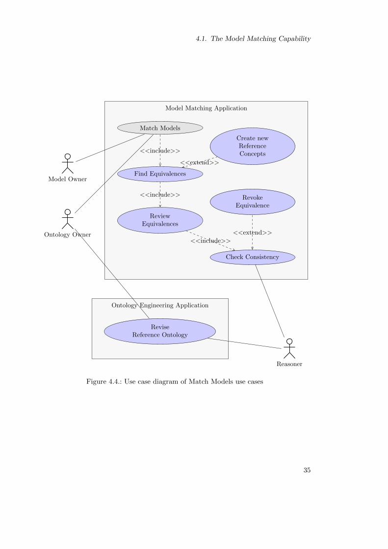
4.1. The Model Matching Capability
Model Matching ApplicationModel Matching Application
Ontology Engineering ApplicationOntology Engineering Application
<<include>>
<<include>>
<<extend>>
<<include>>
<<extend>>
Match Models
Find Equivalences
Create newReferenceConcepts
ReviewEquivalences
Check Consistency
RevokeEquivalence
ReviseReference Ontology
Reasoner
Model Owner
Ontology Owner
Figure 4.4.: Use case diagram of Match Models use cases
35
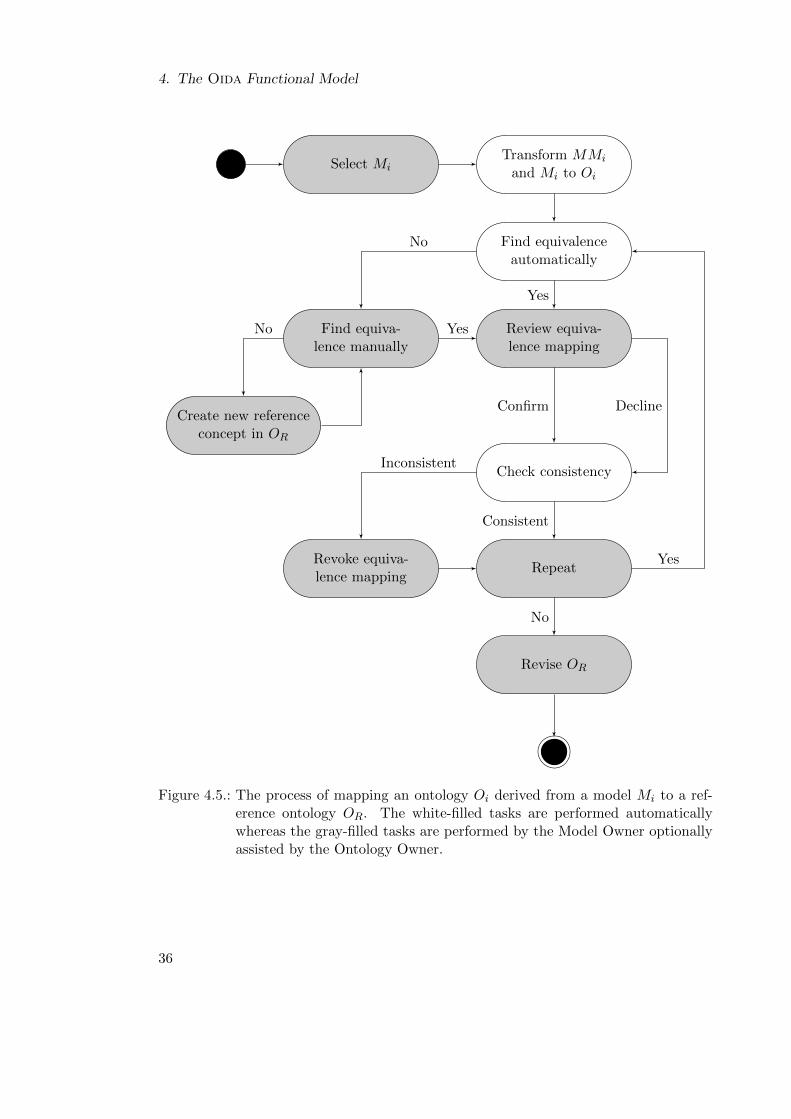
4. The Oida Functional Model
Select MiTransform MMi
and Mi to Oi
Find equivalenceautomatically
Find equiva-lence manually
Review equiva-lence mapping
Create new referenceconcept in OR
Check consistency
RepeatRevoke equiva-lence mapping
Revise OR
No
Yes
YesNo
Confirm Decline
Inconsistent
Consistent
Yes
No
Figure 4.5.: The process of mapping an ontology Oi derived from a model Mi to a ref-erence ontology OR. The white-filled tasks are performed automaticallywhereas the gray-filled tasks are performed by the Model Owner optionallyassisted by the Ontology Owner.
36
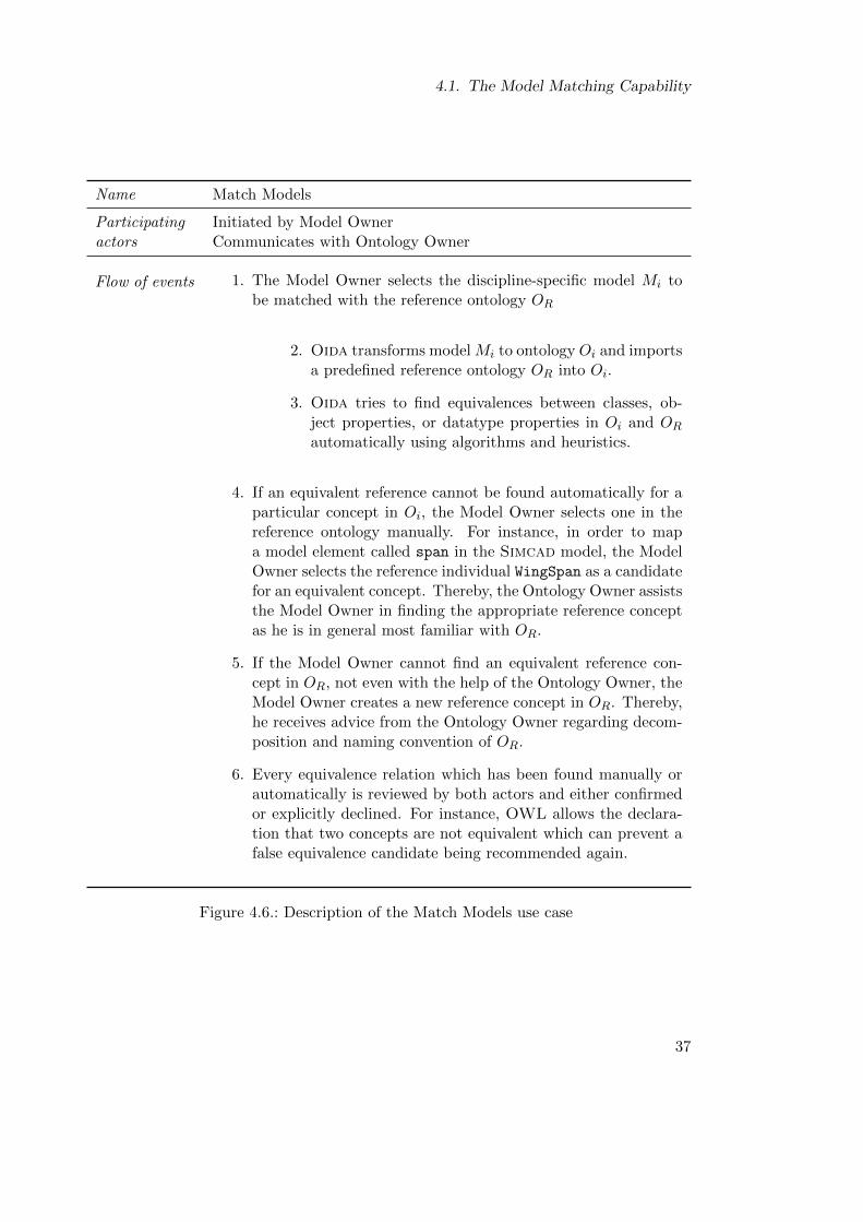
4.1. The Model Matching Capability
Name Match Models
Participating Initiated by Model Owneractors Communicates with Ontology Owner
Flow of events 1. The Model Owner selects the discipline-specific model Mi tobe matched with the reference ontology OR
2. Oida transforms model Mi to ontology Oi and importsa predefined reference ontology OR into Oi.
3. Oida tries to find equivalences between classes, ob-ject properties, or datatype properties in Oi and OR
automatically using algorithms and heuristics.
4. If an equivalent reference cannot be found automatically for aparticular concept in Oi, the Model Owner selects one in thereference ontology manually. For instance, in order to mapa model element called span in the Simcad model, the ModelOwner selects the reference individual WingSpan as a candidatefor an equivalent concept. Thereby, the Ontology Owner assiststhe Model Owner in finding the appropriate reference conceptas he is in general most familiar with OR.
5. If the Model Owner cannot find an equivalent reference con-cept in OR, not even with the help of the Ontology Owner, theModel Owner creates a new reference concept in OR. Thereby,he receives advice from the Ontology Owner regarding decom-position and naming convention of OR.
6. Every equivalence relation which has been found manually orautomatically is reviewed by both actors and either confirmedor explicitly declined. For instance, OWL allows the declara-tion that two concepts are not equivalent which can prevent afalse equivalence candidate being recommended again.
Figure 4.6.: Description of the Match Models use case
37
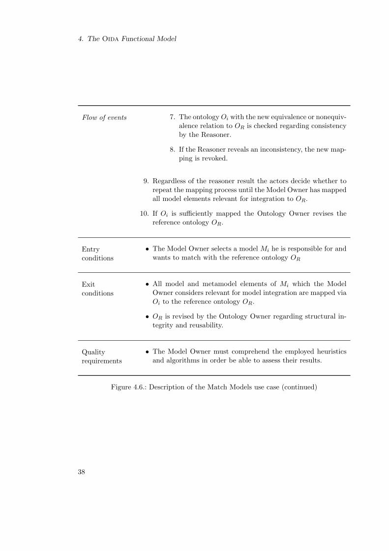
4. The Oida Functional Model
Flow of events 7. The ontology Oi with the new equivalence or nonequiv-alence relation to OR is checked regarding consistencyby the Reasoner.
8. If the Reasoner reveals an inconsistency, the new map-ping is revoked.
9. Regardless of the reasoner result the actors decide whether torepeat the mapping process until the Model Owner has mappedall model elements relevant for integration to OR.
10. If Oi is sufficiently mapped the Ontology Owner revises thereference ontology OR.
Entryconditions
• The Model Owner selects a model Mi he is responsible for andwants to match with the reference ontology OR
Exitconditions
• All model and metamodel elements of Mi which the ModelOwner considers relevant for model integration are mapped viaOi to the reference ontology OR.
• OR is revised by the Ontology Owner regarding structural in-tegrity and reusability.
Qualityrequirements
• The Model Owner must comprehend the employed heuristicsand algorithms in order be able to assess their results.
Figure 4.6.: Description of the Match Models use case (continued)
38
4.1. The Model Matching Capability
has far more individuals than classes. This decision is convenient for matching the givensample models but bears the risk of limited reusability of OR to more domain-specificmetamodels which could specify metaconcepts which are currently implemented as in-stances.
Ontology classes are interrelated by object properties and anonymous classes whichcan be further restricted by logical statements. Automated reasoners can evaluate thesestatements to classify concepts more specifically and to check the consistency of theoverall ontology. Adding restrictions is a nontrivial maintenance task because it repre-sents domain knowledge engineering which should be performed in collaboration with theModel Owner. Such restrictions should be added carefully for two reasons. First, it canbe difficult for a Model Owner to discriminate between fundamental and project-specificconstraints. For instance, most aircraft must have at least two independent engines.For civil aircraft this constraint stems from safety regulations. Military and unmannedapplications may not be subject to this regulation. Accordingly, this constraint wouldlimit OR to civil transport aircraft applications. Therefore, the Ontology Owner shouldfocus on object properties which are evaluated for the generation of matching recom-mendations as this will make the matching process more efficient.
During Model Matching the Model Owners and Ontology Owner can add synonymsto a concept which already exists. Generally, synonyms help the Model Owners andautomated equivalence finders to determine reference concepts during Model Matching.For instance, MaximumTakeOffWeight, MaximumTakeOffMass and their respective ab-breviations MTOW and MTOM are commonly used synonyms. In the reference ontology asynonym relationship must be explicitly declared by an object property. The On-tology Owner has to decide whether the synonym facilitates the automated matchingthrough better results of a name equivalence finder or unnecessarily increases the com-plexity of OR. However, the Model Owners may create reference synonyms which arenot conformal to the reference ontology style guide or create inconsistency. For instance,OR may contain a statement declaring Mass and Weight to be disjoint concepts. If Max-imumTakeOffWeight and MaximumTakeOffMass have been classified as Mass and Weight
respectively, a synonym relationship would lead to an inconsistent ontology.New ontology classes and their instances have to be classified as in a clear and in-
tuitive taxonomy. A clear taxonomy not only helps Model Owners and OntologyOwner manually navigating through ontologies. As classifications are also the mainsource of automated reasoners, they facilitate the detection of inconsistencies but alsothe automated inference of new knowledge.
If the Ontology Owner decides that a new reference concept is beyond the scopeor not conformal to the style guide of OR, he changes, deletes, or moves the conceptto an external ontology. The existing equivalence mappings from ontologies derivedfrom discipline-specific models have to be updated accordingly. Deletion, moving, orrenaming of concepts should be performed by the Ontology Owner in collaboration withthe affected Model Owners in order to foster the common understanding of the scopeand the reference nomenclature.
As shown in Figure 4.4 the Revise Reference Ontology use case is performed in adedicated Ontology Engineering Application. Accordingly, the use case is important for
39
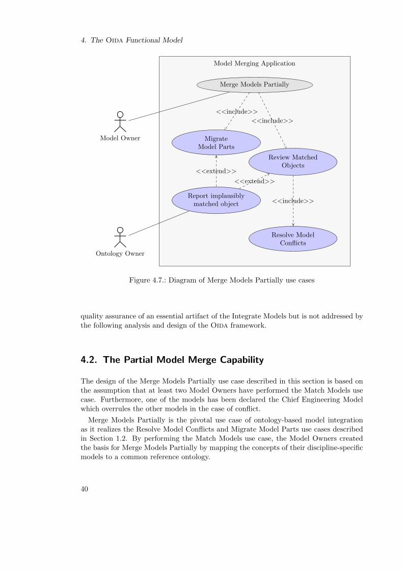
4. The Oida Functional Model
Model Merging ApplicationModel Merging Application
<<include>>
<<include>>
<<include>>
<<extend>>
<<extend>>
Merge Models Partially
Resolve ModelConflicts
MigrateModel Parts
Review MatchedObjects
Report implausiblymatched object
Model Owner
Ontology Owner
Figure 4.7.: Diagram of Merge Models Partially use cases
quality assurance of an essential artifact of the Integrate Models but is not addressed bythe following analysis and design of the Oida framework.
4.2. The Partial Model Merge Capability
The design of the Merge Models Partially use case described in this section is based onthe assumption that at least two Model Owners have performed the Match Models usecase. Furthermore, one of the models has been declared the Chief Engineering Modelwhich overrules the other models in the case of conflict.
Merge Models Partially is the pivotal use case of ontology-based model integrationas it realizes the Resolve Model Conflicts and Migrate Model Parts use cases describedin Section 1.2. By performing the Match Models use case, the Model Owners createdthe basis for Merge Models Partially by mapping the concepts of their discipline-specificmodels to a common reference ontology.
40
4.3. The Co-Evolution Capability
Partial Model Merging includes Resolve Model Conflicts and Migrate Model Parts.These use cases can be performed by the Model Owner without assistance from theOntology Owner within the model integration system.
The activity diagram Figure 4.8 illustrates the linear process of Merge Models Par-tially which is designed to give the Model Owner control over any changes applied duringthe resolution of semantic model conflicts and the migration of model elements. Further-more, the Model Owner is enabled to report detected conflicts or elements proposed formigration which he considers implausible. The flow of events of Merge Models Partiallyis described in more detail in Figure 4.9.
4.3. The Co-Evolution Capability
After performing the Match Models and Merge Models Partially use cases, artifacts, suchas discipline-specific models and ontologies, become coupled by equivalence mappings.As both use cases are usually performed during an active design process, these artifactsare subject to changes which are not automatically propagated to the other coupledartifacts. This section focuses on changes which affect the matching between discipline-specific models and the reference ontology. As these mappings are created in a semi-automated process, their efficient evolution is critical for the overall efficiency of IntegrateModels.
Given an equivalence relationship between two entities, a change that does not affectthe existence or the meaning of both entities leaves the equivalence relation intact.Otherwise, the equivalence relation has to be adjusted. Ideally, this adjustment can beperformed automatically. However, it is a basic assumption of the Match Models usecase that the equivalence mappings between the ontologies derived from the discipline-specific models and the reference ontology cannot be created fully automated but requirea domain expert. Accordingly, if one end of an existing equivalence mapping has beenchanged, it cannot be adjusted automatically in every case.
As the concept of an ontology-based model integration process stipulates a frequentapplication, a high number of manual adjustments by the Model Owner would reduce theoverall process efficiency significantly. The idea of co-evolution of coupled artifacts basedon the hypothesis that if particular changes and their respective reason are recorded bya software system, it can efficiently propagate changes to coupled artifacts. Generally,a small evolutionary change requires a less complex change propagation and thus lessmanual clarifications. Therefore, how different kinds of reasons for change affect modelintegration related artifacts and how this knowledge can increase the applicability ofautomated adjustments of equivalence mappings was investigated. Four use cases de-picted in Figure 4.10 can be discriminated. All of them extend the general Co-EvolveIntegration Artifacts use case:
In Evolve due to Aircraft Modeling the Model Owner changes his model in an aircraftdesign process. The ontology which is derived from the discipline-specific model andits mappings to the reference ontology must be kept consistent. Metamodels of the
41
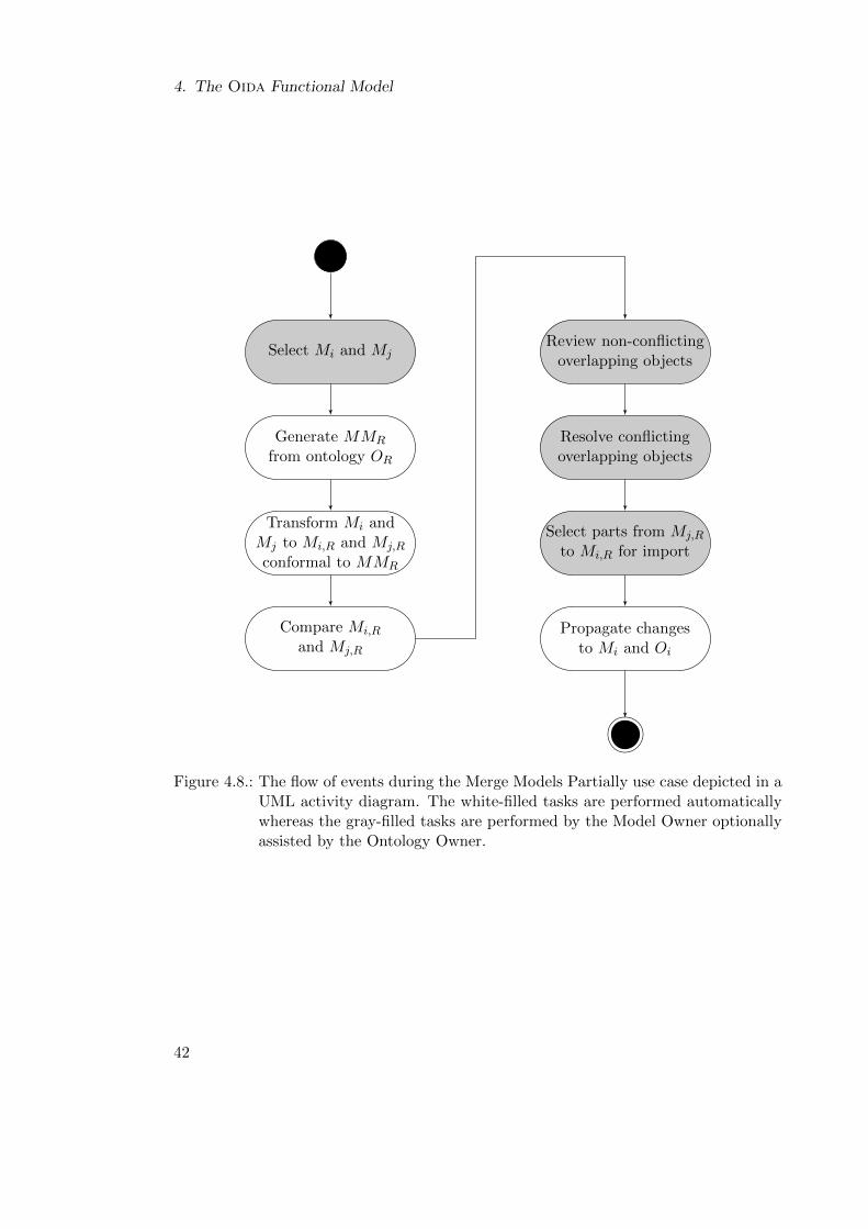
4. The Oida Functional Model
Select Mi and Mj
Generate MMR
from ontology OR
Transform Mi andMj to Mi,R and Mj,R
conformal to MMR
Compare Mi,R
and Mj,R
Review non-conflictingoverlapping objects
Resolve conflictingoverlapping objects
Select parts from Mj,R
to Mi,R for import
Propagate changesto Mi and Oi
Figure 4.8.: The flow of events during the Merge Models Partially use case depicted in aUML activity diagram. The white-filled tasks are performed automaticallywhereas the gray-filled tasks are performed by the Model Owner optionallyassisted by the Ontology Owner.
42
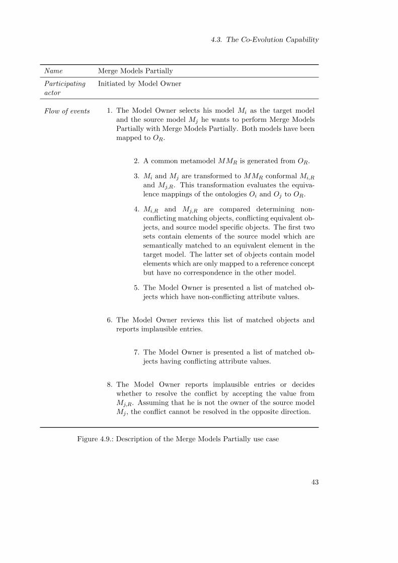
4.3. The Co-Evolution Capability
Name Merge Models Partially
Participating Initiated by Model Owneractor
Flow of events 1. The Model Owner selects his model Mi as the target modeland the source model Mj he wants to perform Merge ModelsPartially with Merge Models Partially. Both models have beenmapped to OR.
2. A common metamodel MMR is generated from OR.
3. Mi and Mj are transformed to MMR conformal Mi,R
and Mj,R. This transformation evaluates the equiva-lence mappings of the ontologies Oi and Oj to OR.
4. Mi,R and Mj,R are compared determining non-conflicting matching objects, conflicting equivalent ob-jects, and source model specific objects. The first twosets contain elements of the source model which aresemantically matched to an equivalent element in thetarget model. The latter set of objects contain modelelements which are only mapped to a reference conceptbut have no correspondence in the other model.
5. The Model Owner is presented a list of matched ob-jects which have non-conflicting attribute values.
6. The Model Owner reviews this list of matched objects andreports implausible entries.
7. The Model Owner is presented a list of matched ob-jects having conflicting attribute values.
8. The Model Owner reports implausible entries or decideswhether to resolve the conflict by accepting the value fromMj,R. Assuming that he is not the owner of the source modelMj , the conflict cannot be resolved in the opposite direction.
Figure 4.9.: Description of the Merge Models Partially use case
43
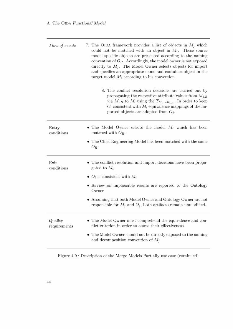
4. The Oida Functional Model
Flow of events 7. The Oida framework provides a list of objects in Mj whichcould not be matched with an object in Mi. These sourcemodel specific objects are presented according to the namingconvention of OR. Accordingly, the model owner is not exposeddirectly to Mj . The Model Owner selects objects for importand specifies an appropriate name and container object in thetarget model Mi according to his convention.
8. The conflict resolution decisions are carried out bypropagating the respective attribute values from Mj,R
via Mi,R to Mi using the TMi→Mi,R. In order to keep
Oi consistent with Mi equivalence mappings of the im-ported objects are adopted from Oj .
Entryconditions
• The Model Owner selects the model Mi which has beenmatched with OR.
• The Chief Engineering Model has been matched with the sameOR.
Exitconditions
• The conflict resolution and import decisions have been propa-gated to Mi
• Oi is consistent with Mi
• Review on implausible results are reported to the OntologyOwner
• Assuming that both Model Owner and Ontology Owner are notresponsible for Mj and Oj , both artifacts remain unmodified.
Qualityrequirements
• The Model Owner must comprehend the equivalence and con-flict criterion in order to assess their effectiveness.
• The Model Owner should not be directly exposed to the namingand decomposition convention of Mj
Figure 4.9.: Description of the Merge Models Partially use case (continued)
44
4.3. The Co-Evolution Capability
discipline-specific models can also be subject to change. However, the propagation ofthis kind of change to the instance model is beyond the scope of this dissertation.
In Evolve due to Model Integration models and ontologies are extended on two occa-sions. First, during the Match Models process new entities can be added to the reference.Second, during Migrate Model Parts new elements are added to the target model. Afterboth processes models and ontologies must be kept consistent to each other. Accordingly,the Evolve due to Model Integration is included in the analysis of the Match Models andMigrate Model Parts. Therefore, the further analysis of Co-Evolve Integration Artifactsdoes not account for it.
The Evolve due to Integration Software Maintenance acknowledges that the imple-mentation of the Oida framework can be subject to change. Especially changes tothe transformation algorithms have consequences for the artifacts of the ontology-basedmodel integration process.
The modification of the reference ontology by the Ontology Owner is treated separatelyin the Evolve due to Reference Ontology Maintenance use case. The source ontologieswhich are mapped to the reference must be kept consistent with those changes.
Modifications on coupled artifacts can be characterized by their impact on topologyand attributes. Topology changes affect relations of entities to each other and thusthe overall structure of a set of entities. In that sense, the creation or the deletion ofa new entity is also a topology change. Attribute changes are value modifications of acharacteristic. The complexity of the consequences of an attribute change depends on theabstraction layer of the attribute. For example, changing the target of an aggregationrelation in a metamodel changes the decomposition structure of objects in instancemodels. In contrast, changing a comma in a description attribute has considerablysmaller implications.
The situation and required action to achieve consistency among co-evolving artifactsdepends on the particular use case. In the following the situation and the respectiverequired actions for topology and attribute changes are described in more detail.
Evolve due to Aircraft Modeling
During the aircraft design process, changes in discipline-specific models can affect thetopology or can be limited to value changes of attributes. The latter kind of modificationis more likely late in the design process when the design of the aircraft configurationhas stabilized. The discipline-specific metamodels are usually not modified during anaircraft design process but more in the context of tool evolution which is not addressedin this dissertation.
Topology Changes Topology changes in models usually do not affect the semantics ofthe objects but the meaning of associations between objects. For instance, if an objectCargoBay is moved from the container object Fuselage to the container object Pres-
surizedCompartments, the former composition association changes the semantics froma component integral object composition to a classification inclusion relation. Accord-ingly, after this modification the semantic properties of the relation from CargoBay to
45
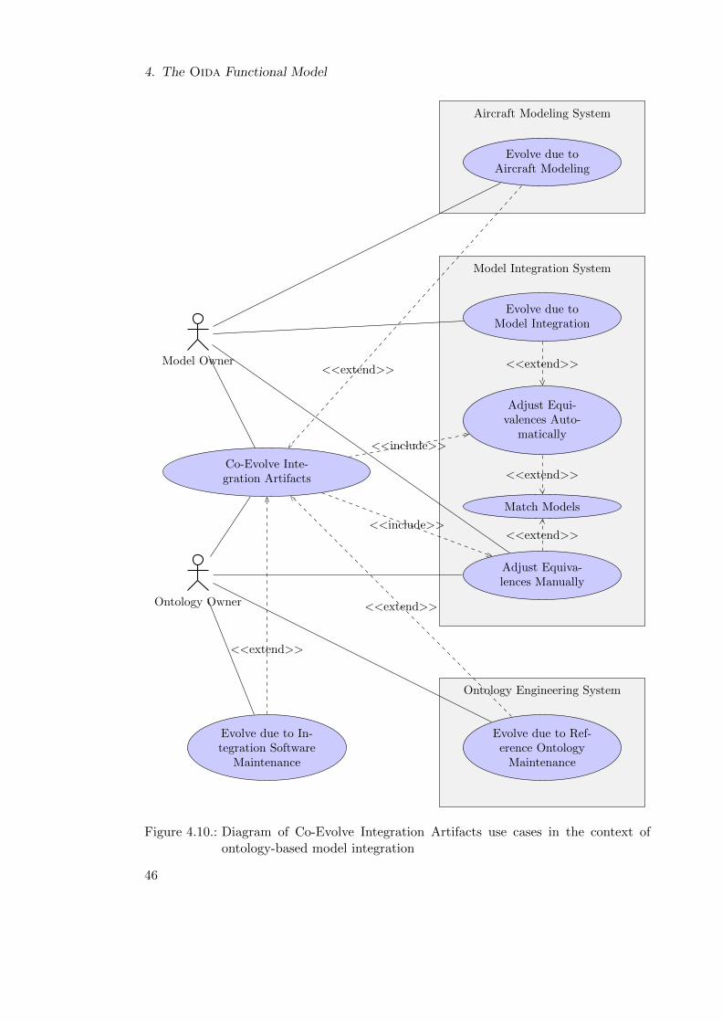
4. The Oida Functional Model
Aircraft Modeling SystemAircraft Modeling System
Model Integration SystemModel Integration System
Ontology Engineering SystemOntology Engineering System
<<extend>> <<extend>>
<<extend>>
<<extend>>
<<extend>>
<<extend>>
<<include>>
<<include>>
Co-Evolve Inte-gration Artifacts
Evolve due toAircraft Modeling
Evolve due toModel Integration
Adjust Equi-valences Auto-
matically
Match Models
Adjust Equiva-lences Manually
Evolve due to In-tegration Software
Maintenance
Evolve due to Ref-erence Ontology
Maintenance
Model Owner
Ontology Owner
Figure 4.10.: Diagram of Co-Evolve Integration Artifacts use cases in the context ofontology-based model integration
46
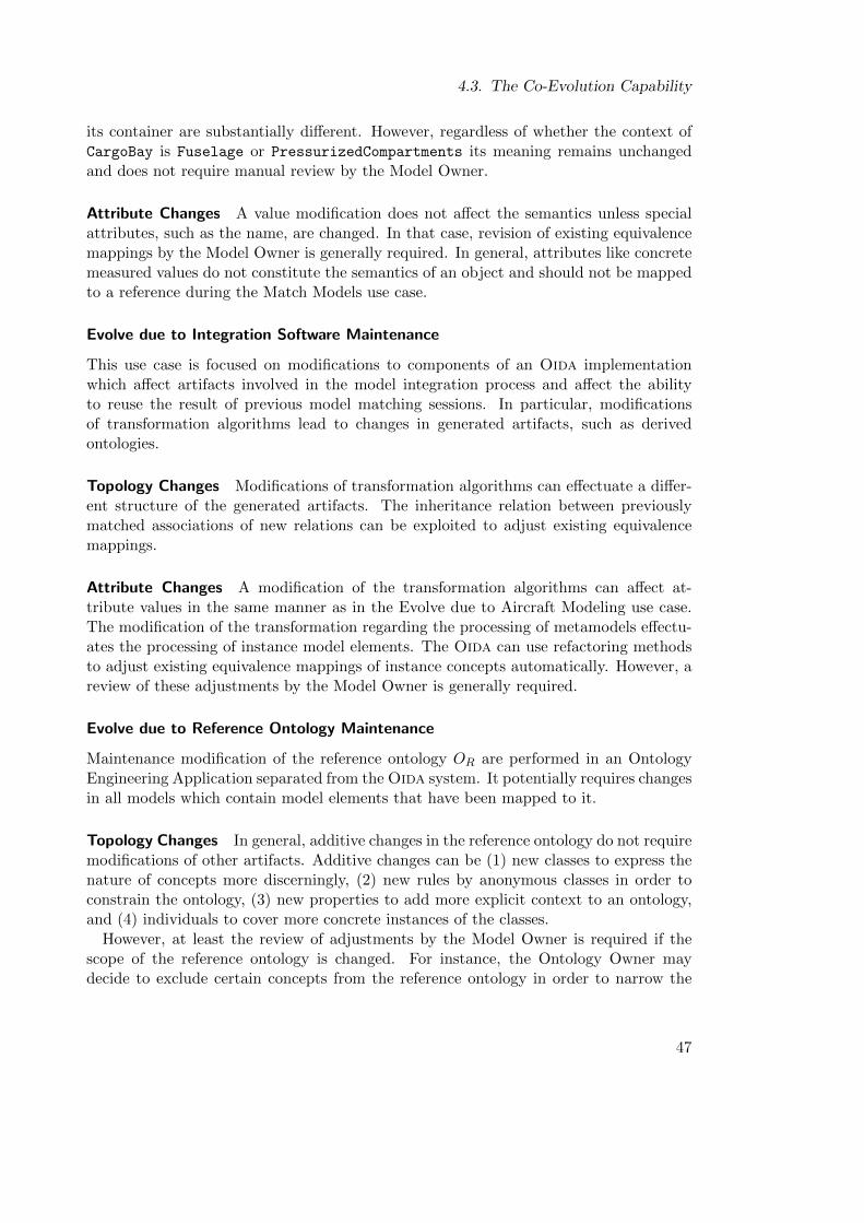
4.3. The Co-Evolution Capability
its container are substantially different. However, regardless of whether the context ofCargoBay is Fuselage or PressurizedCompartments its meaning remains unchangedand does not require manual review by the Model Owner.
Attribute Changes A value modification does not affect the semantics unless specialattributes, such as the name, are changed. In that case, revision of existing equivalencemappings by the Model Owner is generally required. In general, attributes like concretemeasured values do not constitute the semantics of an object and should not be mappedto a reference during the Match Models use case.
Evolve due to Integration Software Maintenance
This use case is focused on modifications to components of an Oida implementationwhich affect artifacts involved in the model integration process and affect the abilityto reuse the result of previous model matching sessions. In particular, modificationsof transformation algorithms lead to changes in generated artifacts, such as derivedontologies.
Topology Changes Modifications of transformation algorithms can effectuate a differ-ent structure of the generated artifacts. The inheritance relation between previouslymatched associations of new relations can be exploited to adjust existing equivalencemappings.
Attribute Changes A modification of the transformation algorithms can affect at-tribute values in the same manner as in the Evolve due to Aircraft Modeling use case.The modification of the transformation regarding the processing of metamodels effectu-ates the processing of instance model elements. The Oida can use refactoring methodsto adjust existing equivalence mappings of instance concepts automatically. However, areview of these adjustments by the Model Owner is generally required.
Evolve due to Reference Ontology Maintenance
Maintenance modification of the reference ontology OR are performed in an OntologyEngineering Application separated from the Oida system. It potentially requires changesin all models which contain model elements that have been mapped to it.
Topology Changes In general, additive changes in the reference ontology do not requiremodifications of other artifacts. Additive changes can be (1) new classes to express thenature of concepts more discerningly, (2) new rules by anonymous classes in order toconstrain the ontology, (3) new properties to add more explicit context to an ontology,and (4) individuals to cover more concrete instances of the classes.
However, at least the review of adjustments by the Model Owner is required if thescope of the reference ontology is changed. For instance, the Ontology Owner maydecide to exclude certain concepts from the reference ontology in order to narrow the
47
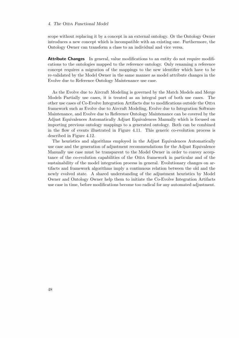
4. The Oida Functional Model
scope without replacing it by a concept in an external ontology. Or the Ontology Ownerintroduces a new concept which is incompatible with an existing one. Furthermore, theOntology Owner can transform a class to an individual and vice versa.
Attribute Changes In general, value modifications to an entity do not require modifi-cations to the ontologies mapped to the reference ontology. Only renaming a referenceconcept requires a migration of the mappings to the new identifier which have to bere-validated by the Model Owner in the same manner as model attribute changes in theEvolve due to Reference Ontology Maintenance use case.
As the Evolve due to Aircraft Modeling is governed by the Match Models and MergeModels Partially use cases, it is treated as an integral part of both use cases. Theother use cases of Co-Evolve Integration Artifacts due to modifications outside the Oidaframework such as Evolve due to Aircraft Modeling, Evolve due to Integration SoftwareMaintenance, and Evolve due to Reference Ontology Maintenance can be covered by theAdjust Equivalences Automatically Adjust Equivalences Manually which is focused onimporting previous ontology mappings to a generated ontology. Both can be combinedin the flow of events illustrated in Figure 4.11. This generic co-evolution process isdescribed in Figure 4.12.
The heuristics and algorithms employed in the Adjust Equivalences Automaticallyuse case and the generation of adjustment recommendations for the Adjust EquivalenceManually use case must be transparent to the Model Owner in order to convey accep-tance of the co-evolution capabilities of the Oida framework in particular and of thesustainability of the model integration process in general. Evolutionary changes on ar-tifacts and framework algorithms imply a continuous relation between the old and thenewly evolved state. A shared understanding of the adjustment heuristics by ModelOwner and Ontology Owner help them to initiate the Co-Evolve Integration Artifactsuse case in time, before modifications become too radical for any automated adjustment.
48
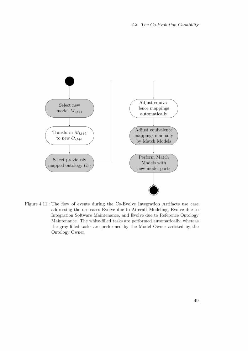
4.3. The Co-Evolution Capability
Select newmodel Mi,t+1
Transform Mi,t+1
to new Oi,t+1
Select previouslymapped ontology Oi,t
Adjust equiva-lence mappingsautomatically
Adjust equivalencemappings manuallyby Match Models
Perform MatchModels with
new model parts
Figure 4.11.: The flow of events during the Co-Evolve Integration Artifacts use caseaddressing the use cases Evolve due to Aircraft Modeling, Evolve due toIntegration Software Maintenance, and Evolve due to Reference OntologyMaintenance. The white-filled tasks are performed automatically, whereasthe gray-filled tasks are performed by the Model Owner assisted by theOntology Owner.
49
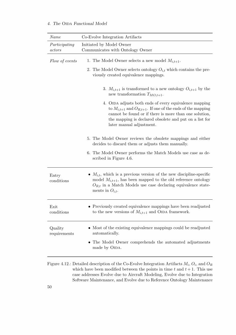
4. The Oida Functional Model
Name Co-Evolve Integration Artifacts
Participating Initiated by Model Owneractors Communicates with Ontology Owner
Flow of events 1. The Model Owner selects a new model Mi,t+1.
2. The Model Owner selects ontology Oi,t which contains the pre-viously created equivalence mappings.
3. Mi,t+1 is transformed to a new ontology Oi,t+1 by thenew transformation TMO,t+1.
4. Oida adjusts both ends of every equivalence mappingto Mi,t+1 and OR,t+1. If one of the ends of the mappingcannot be found or if there is more than one solution,the mapping is declared obsolete and put on a list forlater manual adjustment.
5. The Model Owner reviews the obsolete mappings and eitherdecides to discard them or adjusts them manually.
6. The Model Owner performs the Match Models use case as de-scribed in Figure 4.6.
Entryconditions
• Mi,t, which is a previous version of the new discipline-specificmodel Mi,t+1, has been mapped to the old reference ontologyOR,t in a Match Models use case declaring equivalence state-ments in Oi,t.
Exitconditions
• Previously created equivalence mappings have been readjustedto the new versions of Mi,t+1 and Oida framework.
Qualityrequirements
• Most of the existing equivalence mappings could be readjustedautomatically.
• The Model Owner comprehends the automated adjustmentsmade by Oida.
Figure 4.12.: Detailed description of the Co-Evolve Integration Artifacts Mi, Oi, and OR
which have been modified between the points in time t and t+ 1. This usecase addresses Evolve due to Aircraft Modeling, Evolve due to IntegrationSoftware Maintenance, and Evolve due to Reference Ontology Maintenance
50
5. The Oida Analysis Object Model
”[. . . ] because in the age ofinformation overload the ultimateluxury is meaning and context.”
Wired premiere issue
An analysis object model defines and formalizes participating objects and their rela-tions to each other. The objects are categorized in Entity Objects, Boundary Objects,and Control Objects as defined by Jacobson et al. [JBR99]. Entity Objects representinformation objects which are created or read from external resources, manipulatedand linked with other objects, and destroyed or written to external resources by soft-ware system. Boundary Objects enable the communication of the system with otherexternal systems or actors. Control Objects are concerned with effective and efficientperformance of system components during use cases and their interaction with the usersthrough Boundary Objects. In the following chapter, this analysis is carried out to coverthe participating objects of the Match Models, Merge Models Partially, and Co-EvolveIntegration Artifacts use cases. Additionally, this chapter also elaborates the analysis ofthe ontology-based model transformation TM as an automated operation.
5.1. Analysis Objects of the Match Models Use Case
The Match Models use case enables the matching of semantically equivalent elements ofdifferent discipline-specific models by mapping the discipline-specific concepts extractedfrom the models to concepts in a reference ontology.
The Oida facilitates the semi-automated mapping process by proposing automaticallyidentified equivalences and by supporting the Model Owner in creating equivalence re-lations and in reviewing the relations manually. Thereby, the Ontology Owner beingmore familiar with the capabilities of the Oida and the reference ontology moderatesthe process and guides the Model Owner’s actions in a consultative manner.
In the following, the participating objects of the Match Models use case are identified.The use case is described in Section 4.1.
Figure 5.1 shows Entity Objects and their associations with each other. The usecase is initiated by the Model Owner who selects the DisciplineSpecificModel heowns. This action triggers the generation of the DerivedOntology by the Ontology-
Generator. The EquvivalenceFinder imports the ReferenceOntology and starts cre-ating EquivalenceCandidates if it finds semantically equivalent ReferenceConcepts
for given DisciplineSpecificConcepts. If EquivalenceCandidates cannot be found
51
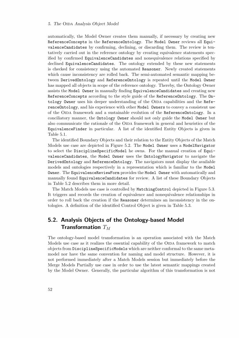
5. The Oida Analysis Object Model
automatically, the Model Owner creates them manually, if necessary by creating newReferenceConcepts in the ReferenceOntology. The Model Owner reviews all Equi-valenceCandidates by confirming, declining, or discarding them. The review is ten-tatively carried out in the reference ontology by creating equivalence statements spec-ified by confirmed EquivalenceCandidates and nonequivalence relations specified bydeclined EquivalenceCandidates. The ontology extended by these new statementsis checked for consistency using the automated Reasoner. Newly created statementswhich cause inconsistency are rolled back. The semi-automated semantic mapping be-tween DerivedOntology and ReferenceOntology is repeated until the Model Owner
has mapped all objects in scope of the reference ontology. Thereby, the Ontology Ownerassists the Model Owner in manually finding EquivalenceCandidates and creating newReferenceConcepts according to the style guide of the ReferenceOntology. The On-
tology Owner uses his deeper understanding of the Oida capabilities and the Refe-
renceOntology, and his experience with other Model Owners to convey a consistent useof the Oida framework and a sustainable evolution of the ReferenceOntology. In aconciliatory manner, the Ontology Owner should not only guide the Model Owner butalso communicate the rationale of the Oida framework in general and heuristics of theEquivalenceFinder in particular. A list of the identified Entity Objects is given inTable 5.1.
The identified Boundary Objects and their relation to the Entity Objects of the MatchModels use case are depicted in Figure 5.2. The Model Owner uses a ModelNavigator
to select the DisciplineSpecificModel he owns. For the manual creation of Equi-
valenceCandidates, the Model Owner uses the OntologyNavigator to navigate theDerivedOntology and ReferenceOntology. The navigators must display the availablemodels and ontologies respectively in a representation which is familiar to the Model
Owner. The EquivalenceReviewForm provides the Model Owner with automatically andmanually found EquivalenceCandidates for review. A list of these Boundary Objectsin Table 5.2 describes them in more detail.
The Match Models use case is controlled by MatchingControl depicted in Figure 5.3.It triggers and records the creation of equivalence and nonequivalence relationships inorder to roll back the creation if the Reasoner determines an inconsistency in the on-tologies. A definition of the identified Control Object is given in Table 5.3.
5.2. Analysis Objects of the Ontology-based ModelTransformation TM
The ontology-based model transformation is an operation associated with the MatchModels use case as it realizes the essential capability of the Oida framework to matchobjects from DisciplineSpecificModels which are neither conformal to the same meta-model nor have the same convention for naming and model structure. However, it isnot performed immediately after a Match Models session but immediately before theMerge Models Partially use case in order to use the latest semantic mappings createdby the Model Owner. Generally, the particular algorithm of this transformation is not
52
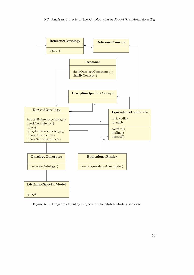
5.2. Analysis Objects of the Ontology-based Model Transformation TM
*
*
*
*
DerivedOntology
importReferenceOntology()checkConsistency()query()queryReferenceOntology()createEquivalence()createNonEquivalence()
ReferenceOntology
query()
OntologyGenerator
generateOntology()
DisciplineSpecificModel
query()
DisciplineSpecificConcept
Reasoner
checkOntologyConsistency()classifyConcept()
EquivalenceFinder
createEquivalenceCandidate()
EquivalenceCandidate
reviewedByfoundBy
confirm()decline()discard()
ReferenceConcept
Figure 5.1.: Diagram of Entity Objects of the Match Models use case
53
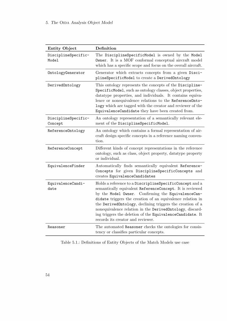
5. The Oida Analysis Object Model
Entity Object Definition
DisciplineSpecific-
Model
The DisciplineSpecificModel is owned by the Model
Owner. It is a MOF conformal conceptual aircraft modelwhich has a specific scope and focus on the overall aircraft.
OntologyGenerator Generator which extracts concepts from a given Disci-
plineSpecificModel to create a DerivedOntology
DerivedOntology This ontology represents the concepts of the Discipline-
SpecificModel, such as ontology classes, object properties,datatype properties, and individuals. It contains equiva-lence or nonequivalence relations to the ReferenceOnto-
logy which are tagged with the creator and reviewer of theEquivalenceCandidate they have been created from.
DisciplineSpecific-
Concept
An ontology representation of a semantically relevant ele-ment of the DisciplineSpecificModel.
ReferenceOntology An ontology which contains a formal representation of air-craft design specific concepts in a reference naming conven-tion.
ReferenceConcept Different kinds of concept representations in the referenceontology, such as class, object property, datatype propertyor individual.
EquivalenceFinder Automatically finds semantically equivalent Reference-
Concepts for given DisciplineSpecificConcepts andcreates EquivalenceCandidates
EquivalenceCandi-
date
Holds a reference to a DiscriplineSpecificConcept and asemantically equivalent ReferenceConcept. It is reviewedby the Model Owner. Confirming the EquivalenceCan-
didate triggers the creation of an equivalence relation inthe DerivedOntology, declining triggers the creation of anonequivalence relation in the DerivedOntology, discard-ing triggers the deletion of the EquivalenceCandidate. Itrecords its creator and reviewer.
Reasoner The automated Reasoner checks the ontologies for consis-tency or classifies particular concepts.
Table 5.1.: Definitions of Entity Objects of the Match Models use case
54
5.2. Analysis Objects of the Ontology-based Model Transformation TM
*
*
*
DerivedOntology
importReferenceOntology()checkConsistency()query()queryReferenceOntology()createEquivalence()createNonEquivalence()
ReferenceOntology
query()
DisciplineSpecificModel
query()
OntologyNavigatorForm
createReferenceConcept()createEquivalenceCandidate()
ModelNavigatorForm
selectModelElement()
EquivalenceReviewForm
reviewEquivalenceCandidate()
EquivalenceCandidate
reviewedByfoundBy
confirm()decline()discard()
Figure 5.2.: Diagram of Boundary Objects of the Match Models use case
Boundary Object Definition
ModelNavigatorForm Displays available MOF conformal DisciplineSpecific-Models and allows the Model Owner to select a model hewants to match.
OntologyNavigatorForm Supports the Model Owner to manually find Equiva-
lenceCandidates by presenting DisciplineSpecific-
Concepts and ReferenceConcepts in a structure whichis clear and intuitive.
EquivalenceReviewForm Supports the Model Owner in the review of Equivalence-Candidates
Table 5.2.: Definitions of Boundary Objects of the Match Models use case
55
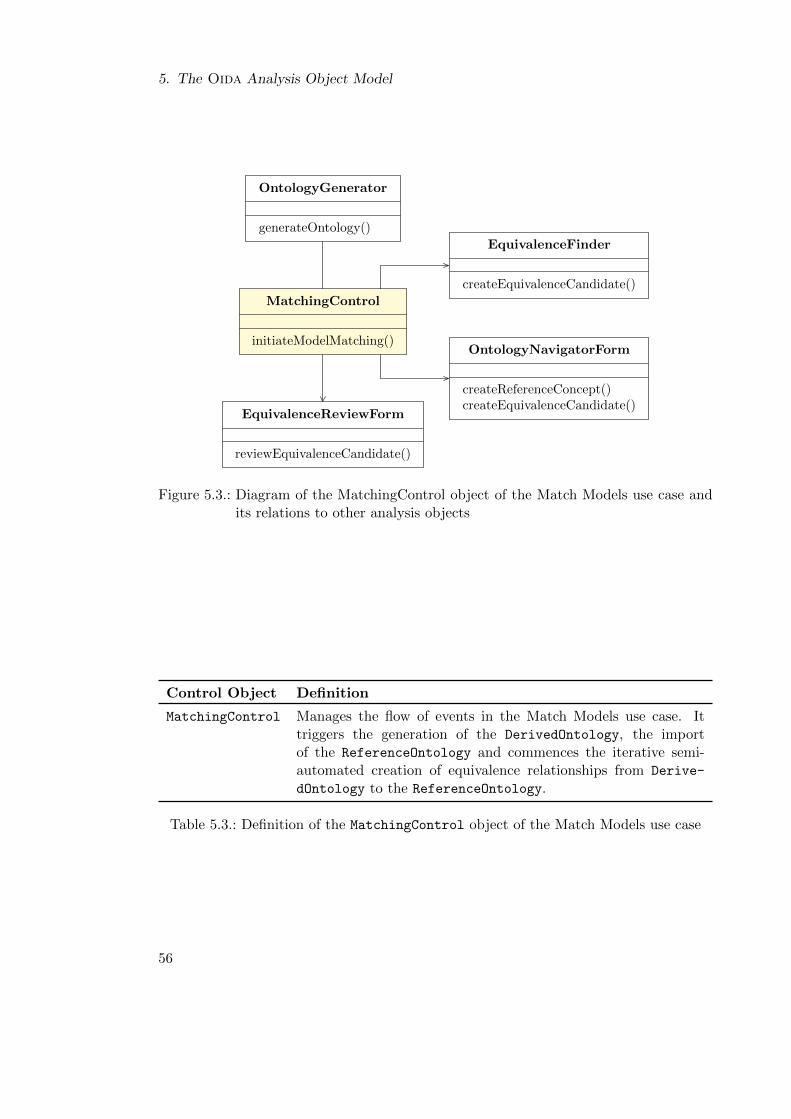
5. The Oida Analysis Object Model
MatchingControl
initiateModelMatching()
OntologyGenerator
generateOntology()
EquivalenceFinder
createEquivalenceCandidate()
OntologyNavigatorForm
createReferenceConcept()createEquivalenceCandidate()
EquivalenceReviewForm
reviewEquivalenceCandidate()
Figure 5.3.: Diagram of the MatchingControl object of the Match Models use case andits relations to other analysis objects
Control Object Definition
MatchingControl Manages the flow of events in the Match Models use case. Ittriggers the generation of the DerivedOntology, the importof the ReferenceOntology and commences the iterative semi-automated creation of equivalence relationships from Derive-
dOntology to the ReferenceOntology.
Table 5.3.: Definition of the MatchingControl object of the Match Models use case
56
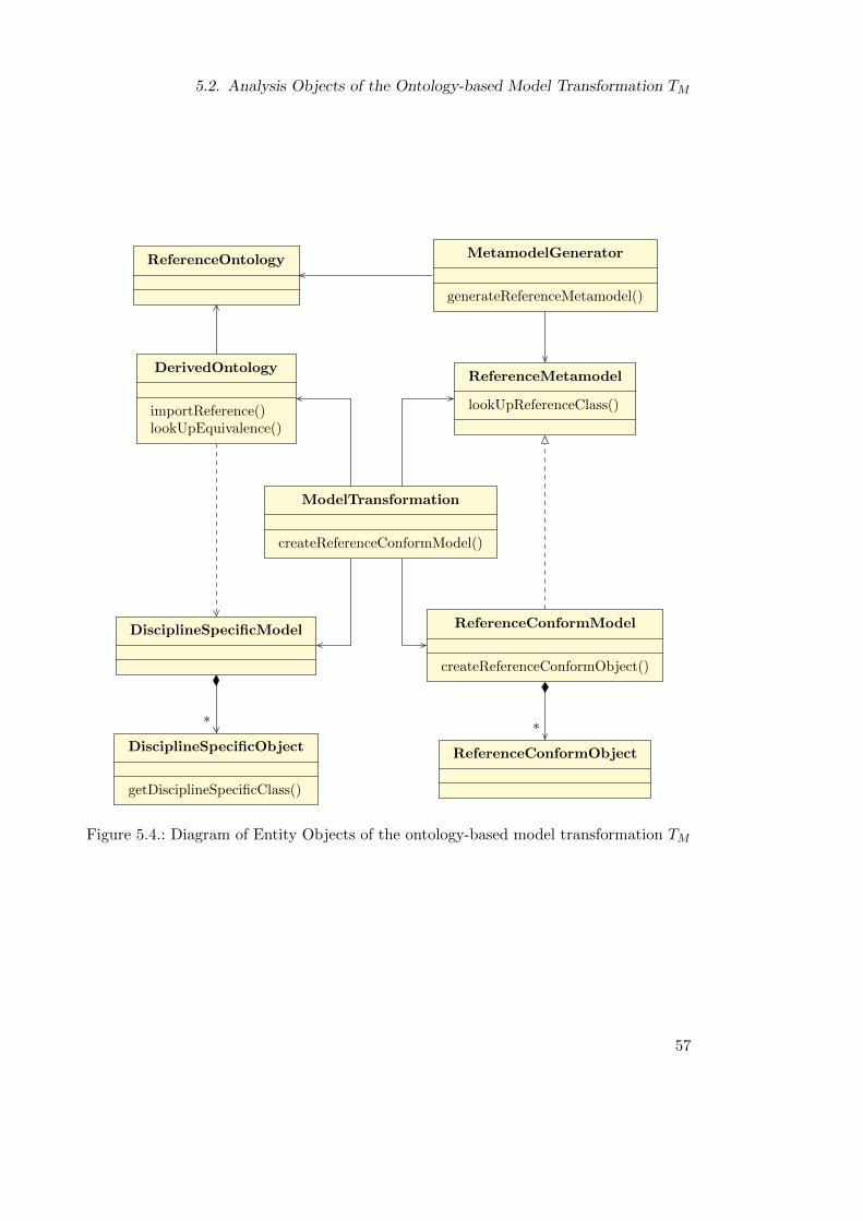
5.2. Analysis Objects of the Ontology-based Model Transformation TM
* *
DisciplineSpecificModel
DisciplineSpecificObject
getDisciplineSpecificClass()
DerivedOntology
importReference()lookUpEquivalence()
ReferenceOntology
ModelTransformation
createReferenceConformModel()
MetamodelGenerator
generateReferenceMetamodel()
ReferenceConformModel
createReferenceConformObject()
ReferenceConformObject
ReferenceMetamodel
lookUpReferenceClass()
Figure 5.4.: Diagram of Entity Objects of the ontology-based model transformation TM
57
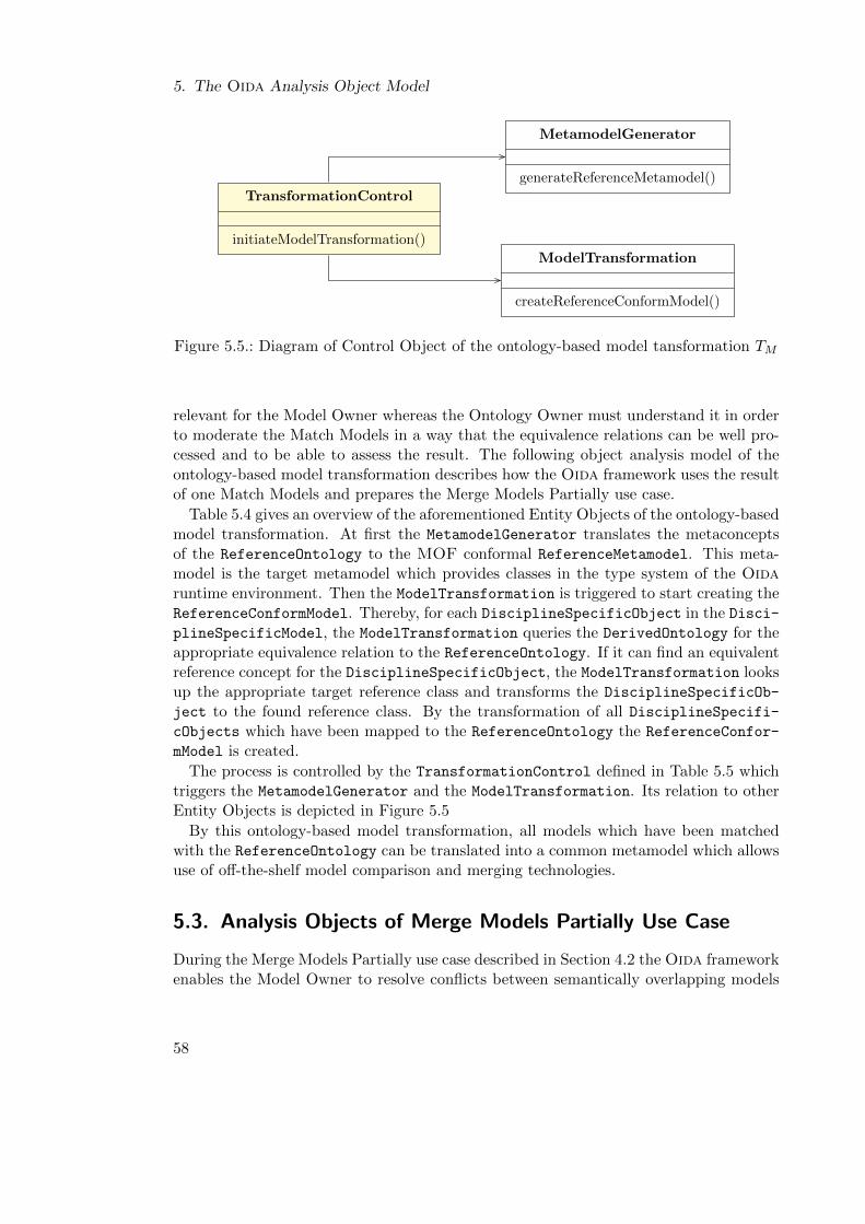
5. The Oida Analysis Object Model
TransformationControl
initiateModelTransformation()
MetamodelGenerator
generateReferenceMetamodel()
ModelTransformation
createReferenceConformModel()
Figure 5.5.: Diagram of Control Object of the ontology-based model tansformation TM
relevant for the Model Owner whereas the Ontology Owner must understand it in orderto moderate the Match Models in a way that the equivalence relations can be well pro-cessed and to be able to assess the result. The following object analysis model of theontology-based model transformation describes how the Oida framework uses the resultof one Match Models and prepares the Merge Models Partially use case.
Table 5.4 gives an overview of the aforementioned Entity Objects of the ontology-basedmodel transformation. At first the MetamodelGenerator translates the metaconceptsof the ReferenceOntology to the MOF conformal ReferenceMetamodel. This meta-model is the target metamodel which provides classes in the type system of the Oidaruntime environment. Then the ModelTransformation is triggered to start creating theReferenceConformModel. Thereby, for each DisciplineSpecificObject in the Disci-plineSpecificModel, the ModelTransformation queries the DerivedOntology for theappropriate equivalence relation to the ReferenceOntology. If it can find an equivalentreference concept for the DisciplineSpecificObject, the ModelTransformation looksup the appropriate target reference class and transforms the DisciplineSpecificOb-
ject to the found reference class. By the transformation of all DisciplineSpecifi-cObjects which have been mapped to the ReferenceOntology the ReferenceConfor-
mModel is created.
The process is controlled by the TransformationControl defined in Table 5.5 whichtriggers the MetamodelGenerator and the ModelTransformation. Its relation to otherEntity Objects is depicted in Figure 5.5
By this ontology-based model transformation, all models which have been matchedwith the ReferenceOntology can be translated into a common metamodel which allowsuse of off-the-shelf model comparison and merging technologies.
5.3. Analysis Objects of Merge Models Partially Use Case
During the Merge Models Partially use case described in Section 4.2 the Oida frameworkenables the Model Owner to resolve conflicts between semantically overlapping models
58
5.3. Analysis Objects of Merge Models Partially Use Case
Entity Object Definition
MetamodelGenerator Translates the ReferenceOntology into the type sys-tem of the runtime environment of the Oida frameworkgenerating a ReferenceMetamodel.
ReferenceOntology See Table 5.1
ReferenceMetamodel MOF conformal metamodel generated from the Refe-
renceOntology providing the concepts of the referenceontology in the type system of the Merge Models Par-tially runtime environment.
ModelTransformation Transforms all objects of a DisciplineSpecificModel
to objects in the ReferenceConformModel. Thereby,for the creation of a new ReferenceObject as instanceof the equivalent class of the ReferenceMetamodel, itqueries the DerivedOntology for the equivalence map-ping of each DisciplineSpecificObject to the Refe-
renceOntology.
DisciplineSpecificModel See Table 5.1.
DerivedOntology See Table 5.1.
ReferenceConformModel A model which conforms to the ReferenceMetamodel
and has been generated from the DisciplineSpeci-
ficModel by ModelTransformation.
Table 5.4.: Definitions of Entity Objects of the ontology-based transformation of modelsto a common reference metamodel
Control Object Definition
TransformationControl Manages the ontology-based model transformation bytriggering the MetamodelGenerator and the ModelTrans-formation. Thereby, it keeps track of the mapping be-tween DisciplineSpecificObjects and ReferenceCon-
formObjects.
Table 5.5.: Definition of the Control Object of ontology-based transformation of modelsto a common reference metamodel
59
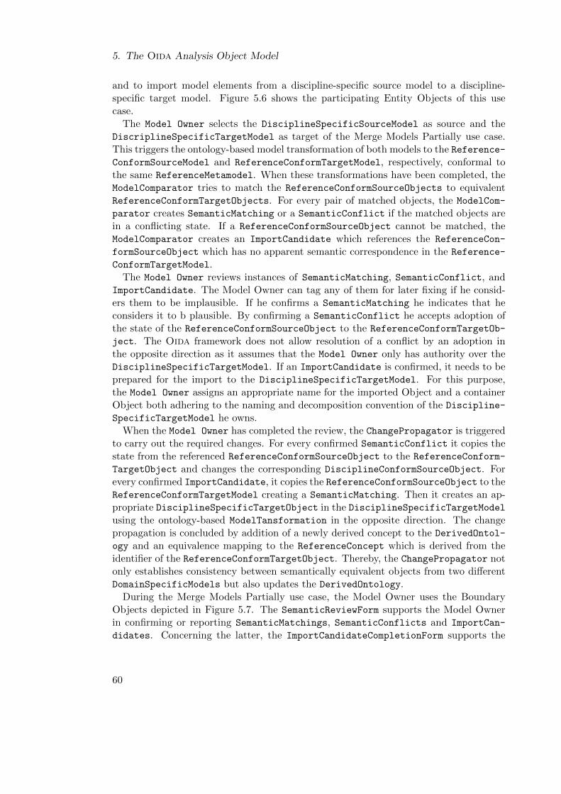
5. The Oida Analysis Object Model
and to import model elements from a discipline-specific source model to a discipline-specific target model. Figure 5.6 shows the participating Entity Objects of this usecase.
The Model Owner selects the DisciplineSpecificSourceModel as source and theDiscriplineSpecificTargetModel as target of the Merge Models Partially use case.This triggers the ontology-based model transformation of both models to the Reference-ConformSourceModel and ReferenceConformTargetModel, respectively, conformal tothe same ReferenceMetamodel. When these transformations have been completed, theModelComparator tries to match the ReferenceConformSourceObjects to equivalentReferenceConformTargetObjects. For every pair of matched objects, the ModelCom-
parator creates SemanticMatching or a SemanticConflict if the matched objects arein a conflicting state. If a ReferenceConformSourceObject cannot be matched, theModelComparator creates an ImportCandidate which references the ReferenceCon-
formSourceObject which has no apparent semantic correspondence in the Reference-
ConformTargetModel.The Model Owner reviews instances of SemanticMatching, SemanticConflict, and
ImportCandidate. The Model Owner can tag any of them for later fixing if he consid-ers them to be implausible. If he confirms a SemanticMatching he indicates that heconsiders it to b plausible. By confirming a SemanticConflict he accepts adoption ofthe state of the ReferenceConformSourceObject to the ReferenceConformTargetOb-
ject. The Oida framework does not allow resolution of a conflict by an adoption inthe opposite direction as it assumes that the Model Owner only has authority over theDisciplineSpecificTargetModel. If an ImportCandidate is confirmed, it needs to beprepared for the import to the DisciplineSpecificTargetModel. For this purpose,the Model Owner assigns an appropriate name for the imported Object and a containerObject both adhering to the naming and decomposition convention of the Discipline-
SpecificTargetModel he owns.When the Model Owner has completed the review, the ChangePropagator is triggered
to carry out the required changes. For every confirmed SemanticConflict it copies thestate from the referenced ReferenceConformSourceObject to the ReferenceConform-
TargetObject and changes the corresponding DisciplineConformSourceObject. Forevery confirmed ImportCandidate, it copies the ReferenceConformSourceObject to theReferenceConformTargetModel creating a SemanticMatching. Then it creates an ap-propriate DisciplineSpecificTargetObject in the DisciplineSpecificTargetModelusing the ontology-based ModelTansformation in the opposite direction. The changepropagation is concluded by addition of a newly derived concept to the DerivedOntol-
ogy and an equivalence mapping to the ReferenceConcept which is derived from theidentifier of the ReferenceConformTargetObject. Thereby, the ChangePropagator notonly establishes consistency between semantically equivalent objects from two differentDomainSpecificModels but also updates the DerivedOntology.
During the Merge Models Partially use case, the Model Owner uses the BoundaryObjects depicted in Figure 5.7. The SemanticReviewForm supports the Model Ownerin confirming or reporting SemanticMatchings, SemanticConflicts and ImportCan-
didates. Concerning the latter, the ImportCandidateCompletionForm supports the
60
5.3. Analysis Objects of Merge Models Partially Use Case
*
*
SemanticMatching
reviewedBy
report()confirm()
ModelComparator
compareModels()createSemanticMatchings()
ReferenceMetamodel
ChangePropagator
propagateChanges()
ReferenceConformTargetModel ReferenceConformSourceModel
ReferenceConformTargetObject ReferenceConformSourceObject
SemanticConflict
resolveConflict()
ImportCandidate
setDisciplineSpecificName()setDisciplineSpecificContext()
DisciplineSpecificTargetModel
changeStructuralFeatures()createNewObject()
DerivedOntology
createEquivalence()
Figure 5.6.: Diagram of Entity Objects of the Merge Models Partially use case
61
5. The Oida Analysis Object Model
Entity Object Definition
ChiefEngineering-
Model
A kind of DisciplineSpecificModel which is owned by theChief Engineer who is entitled to finally decide on design con-flicts.
LegacyModel A kind of DisciplineSpecificModel which has been devel-oped in preceding aircraft design projects.
DisciplineSpecific-
SourceModel
A kind of DisciplineSpecificModel which is selected by theModel Owner for Merge Models Partially. It can be a Legacy
Model or the Chief Engineering Model. The Model Owneris usually not entitled to modify it.
ReferenceMetamodel See Table 5.4
ReferenceConform-
SourceModel
A kind of ReferenceConformModel which has been trans-formed from the DisciplineSpecificTargetModel. TheModel Owner wants to integrate his DisciplineSpecific-
TargetModel with it as it is usually the Chief EngineeringModel
ReferenceConform-
SourceObject
A kind of ReferenceConformObject which has been trans-formed from the DisciplineSpecificSourceModel
ReferenceConform-
TargetModel
A kind of ReferenceConformModel which is owned by theModel Owner. This model is the target of the ReferenceCon-
formSourceObjects which the Model Owner wants to import.It contains ReferenceConformTargetObjects.
ReferenceConform-
TargetObject
A kind of ReferenceConformObject which has been trans-formed from the DisciplineSpecificTargetModel.
ModelComparator Compares two models conformal to the same Refer-
enceMetamodel creating SemanticMatchings between equiv-alent ReferenceConformSourceObjects and Reference-
ConformTargetObjects or a SemanticConflict if the objectsare in a conflicting state. It creates ImportCandidates fromthe ReferenceConformSourceObjects it cannot match.
SemanticConflict A kind of SemanticMapping between two objects in a conflict-ing state. The conflict can be resolved by adopting the stateof the source object.
ImportCandidate Reference to an unmatched ReferenceConformSourceObject
which can be imported into the DisciplineSpecificTarget-Model if the Model Owner specifies a name and container forthe object, conformal to the naming and structure conventionof the target model.
Table 5.6.: Definitions of Entity Objects of the Merge Models Partially use case
62
5.3. Analysis Objects of Merge Models Partially Use Case
Entity Object Definition
ChangePropagator Propagates the conflict resolution and import decisions of theModel Owner to his DisciplineSpecificTargetModel and itslatest DerivedOntology.
DisciplineSpecific-
TargetModel
A kind of DisciplineSpecificModel owned by the ModelOwner. In this model, the ChangePropagation changes thestate of existing objects to resolve conflicts with the sourcemodel and creates new objects which have been imported fromthe source model.
DerivedOntology The ontology derived from the DisciplineSpecificTarget-
Model is a target of ChangePropagation which creates newderived concepts and maps them to the ReferenceOntology
(see Table 5.1).
Table 5.6.: Definitions of Entity Objects of the Merge Models Partially use case(continued)
Model Owner in specifying a domain-specific name and container object for the respec-tive ImportCandidate. These Boundary Objects are defined in Table 5.2 in more detail.
The Merge Models Partially use case is controlled by PartialMergingControl definedin Table 5.8. This Control Object and its relation to other Analysis Objects are depictedin Figure 5.8. It starts the Ontology-based Model Transformation after the Model Ownerhas selected the source and the target model of the current Merge Models Partially usecase. At the end of the use case when the Model Owner has completed the review ofSemanticMatchings and SemanticConflicts as well as the selection and preparationof the ImportCandidates, it starts the ChangePropagator.
Boundary Object Definition
SemanticMatchingReviewForm Supports the Model Owner in reviewing and de-ciding on conflicting SemanticMatchings andSemanticConflicts.
ImportCandidateCompletionForm Supports the Model Owner in selecting and com-pleting ImportCandidates. Thereby, it con-tains a ModelNavigator which allows selectionof new existing or creation of new container ob-jects in the DisciplineSpecificTargetModel.
Table 5.7.: Definitions of Boundary Objects of the Merge Models Partially use case
63
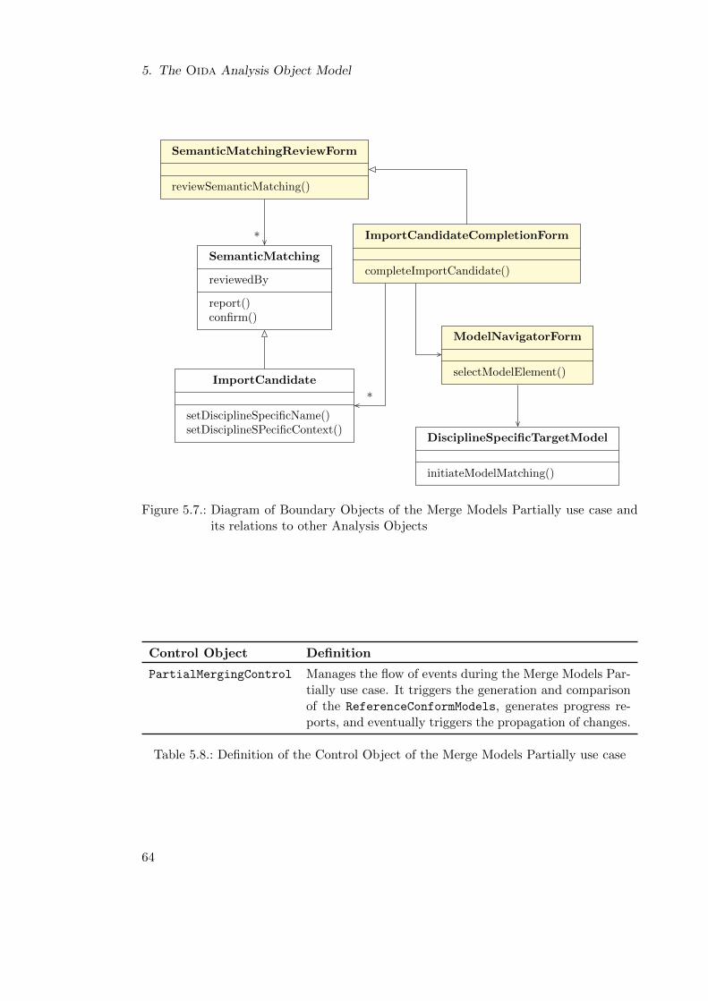
5. The Oida Analysis Object Model
*
*
SemanticMatching
reviewedBy
report()confirm()
SemanticMatchingReviewForm
reviewSemanticMatching()
ImportCandidateCompletionForm
completeImportCandidate()
ModelNavigatorForm
selectModelElement()
DisciplineSpecificTargetModel
initiateModelMatching()
ImportCandidate
setDisciplineSpecificName()setDisciplineSPecificContext()
Figure 5.7.: Diagram of Boundary Objects of the Merge Models Partially use case andits relations to other Analysis Objects
Control Object Definition
PartialMergingControl Manages the flow of events during the Merge Models Par-tially use case. It triggers the generation and comparisonof the ReferenceConformModels, generates progress re-ports, and eventually triggers the propagation of changes.
Table 5.8.: Definition of the Control Object of the Merge Models Partially use case
64
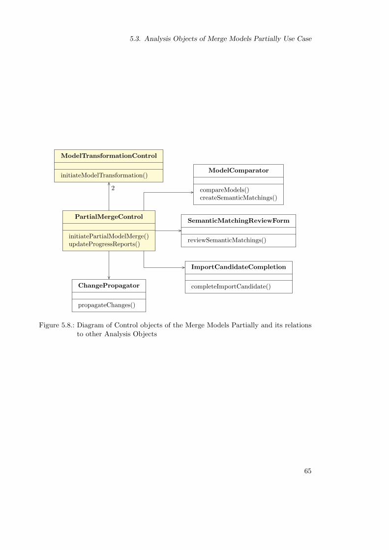
5.3. Analysis Objects of Merge Models Partially Use Case
2
PartialMergeControl
initiatePartialModelMerge()updateProgressReports()
ModelTransformationControl
initiateModelTransformation()ModelComparator
compareModels()createSemanticMatchings()
SemanticMatchingReviewForm
reviewSemanticMatchings()
ImportCandidateCompletion
completeImportCandidate()ChangePropagator
propagateChanges()
Figure 5.8.: Diagram of Control objects of the Merge Models Partially and its relationsto other Analysis Objects
65
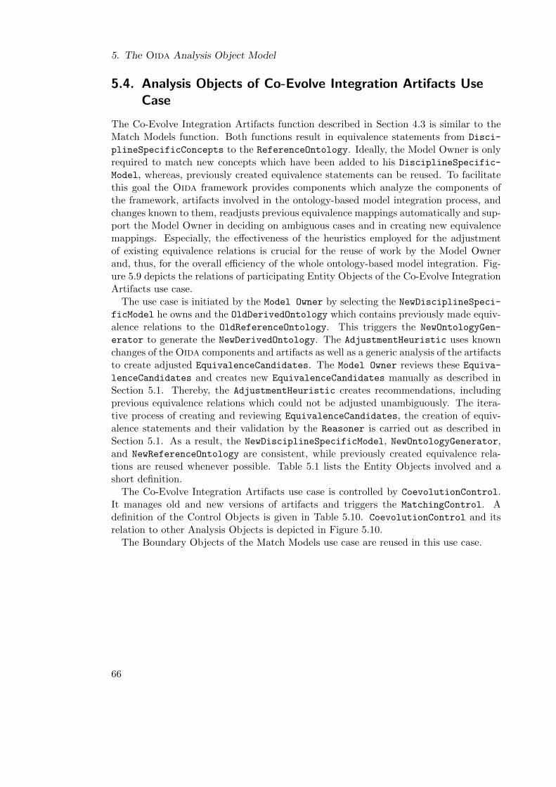
5. The Oida Analysis Object Model
5.4. Analysis Objects of Co-Evolve Integration Artifacts UseCase
The Co-Evolve Integration Artifacts function described in Section 4.3 is similar to theMatch Models function. Both functions result in equivalence statements from Disci-
plineSpecificConcepts to the ReferenceOntology. Ideally, the Model Owner is onlyrequired to match new concepts which have been added to his DisciplineSpecific-
Model, whereas, previously created equivalence statements can be reused. To facilitatethis goal the Oida framework provides components which analyze the components ofthe framework, artifacts involved in the ontology-based model integration process, andchanges known to them, readjusts previous equivalence mappings automatically and sup-port the Model Owner in deciding on ambiguous cases and in creating new equivalencemappings. Especially, the effectiveness of the heuristics employed for the adjustmentof existing equivalence relations is crucial for the reuse of work by the Model Ownerand, thus, for the overall efficiency of the whole ontology-based model integration. Fig-ure 5.9 depicts the relations of participating Entity Objects of the Co-Evolve IntegrationArtifacts use case.
The use case is initiated by the Model Owner by selecting the NewDisciplineSpeci-
ficModel he owns and the OldDerivedOntology which contains previously made equiv-alence relations to the OldReferenceOntology. This triggers the NewOntologyGen-
erator to generate the NewDerivedOntology. The AdjustmentHeuristic uses knownchanges of the Oida components and artifacts as well as a generic analysis of the artifactsto create adjusted EquivalenceCandidates. The Model Owner reviews these Equiva-
lenceCandidates and creates new EquivalenceCandidates manually as described inSection 5.1. Thereby, the AdjustmentHeuristic creates recommendations, includingprevious equivalence relations which could not be adjusted unambiguously. The itera-tive process of creating and reviewing EquivalenceCandidates, the creation of equiv-alence statements and their validation by the Reasoner is carried out as described inSection 5.1. As a result, the NewDisciplineSpecificModel, NewOntologyGenerator,and NewReferenceOntology are consistent, while previously created equivalence rela-tions are reused whenever possible. Table 5.1 lists the Entity Objects involved and ashort definition.
The Co-Evolve Integration Artifacts use case is controlled by CoevolutionControl.It manages old and new versions of artifacts and triggers the MatchingControl. Adefinition of the Control Objects is given in Table 5.10. CoevolutionControl and itsrelation to other Analysis Objects is depicted in Figure 5.10.
The Boundary Objects of the Match Models use case are reused in this use case.
66
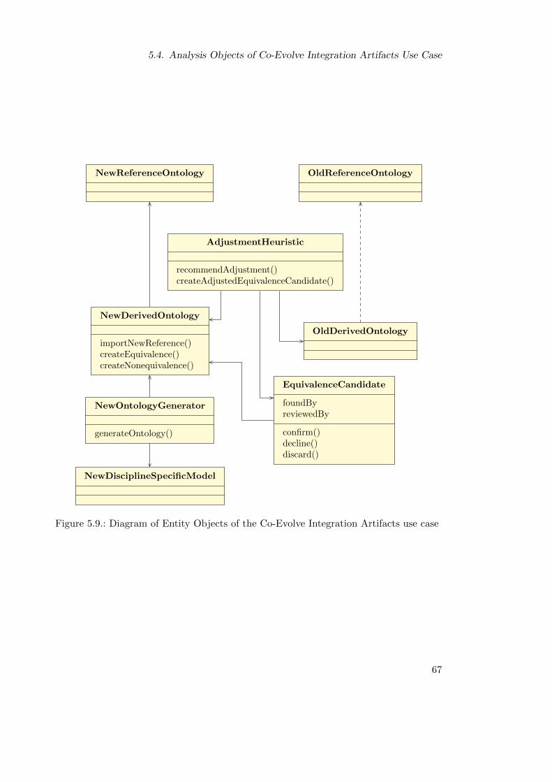
5.4. Analysis Objects of Co-Evolve Integration Artifacts Use Case
AdjustmentHeuristic
recommendAdjustment()createAdjustedEquivalenceCandidate()
OldReferenceOntology
OldDerivedOntology
EquivalenceCandidate
foundByreviewedBy
confirm()decline()discard()
NewDerivedOntology
importNewReference()createEquivalence()createNonequivalence()
NewReferenceOntology
NewOntologyGenerator
generateOntology()
NewDisciplineSpecificModel
Figure 5.9.: Diagram of Entity Objects of the Co-Evolve Integration Artifacts use case
67
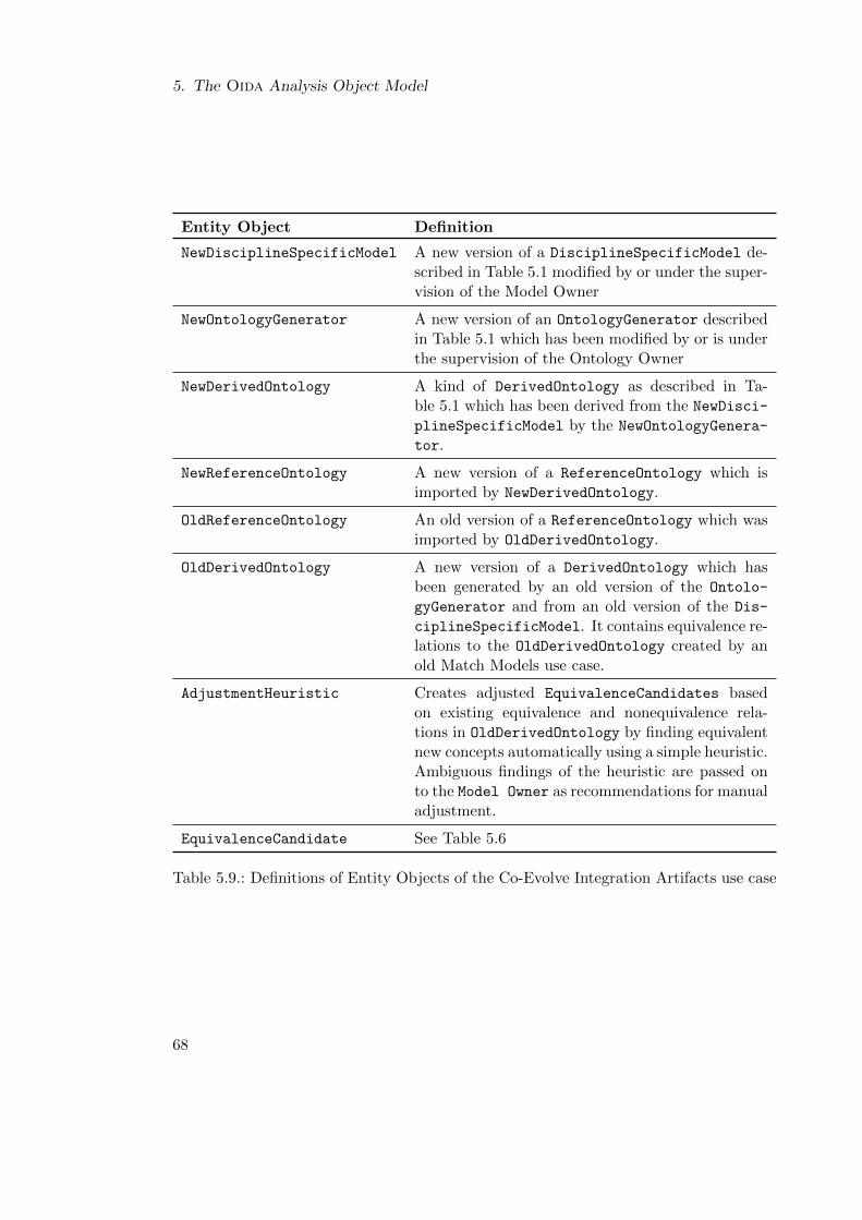
5. The Oida Analysis Object Model
Entity Object Definition
NewDisciplineSpecificModel A new version of a DisciplineSpecificModel de-scribed in Table 5.1 modified by or under the super-vision of the Model Owner
NewOntologyGenerator A new version of an OntologyGenerator describedin Table 5.1 which has been modified by or is underthe supervision of the Ontology Owner
NewDerivedOntology A kind of DerivedOntology as described in Ta-ble 5.1 which has been derived from the NewDisci-
plineSpecificModel by the NewOntologyGenera-
tor.
NewReferenceOntology A new version of a ReferenceOntology which isimported by NewDerivedOntology.
OldReferenceOntology An old version of a ReferenceOntology which wasimported by OldDerivedOntology.
OldDerivedOntology A new version of a DerivedOntology which hasbeen generated by an old version of the Ontolo-
gyGenerator and from an old version of the Dis-
ciplineSpecificModel. It contains equivalence re-lations to the OldDerivedOntology created by anold Match Models use case.
AdjustmentHeuristic Creates adjusted EquivalenceCandidates basedon existing equivalence and nonequivalence rela-tions in OldDerivedOntology by finding equivalentnew concepts automatically using a simple heuristic.Ambiguous findings of the heuristic are passed onto the Model Owner as recommendations for manualadjustment.
EquivalenceCandidate See Table 5.6
Table 5.9.: Definitions of Entity Objects of the Co-Evolve Integration Artifacts use case
68
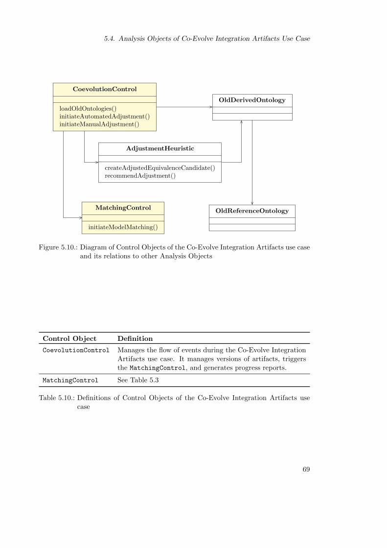
5.4. Analysis Objects of Co-Evolve Integration Artifacts Use Case
CoevolutionControl
loadOldOntologies()initiateAutomatedAdjustment()initiateManualAdjustment()
OldDerivedOntology
OldReferenceOntology
AdjustmentHeuristic
createAdjustedEquivalenceCandidate()recommendAdjustment()
MatchingControl
initiateModelMatching()
Figure 5.10.: Diagram of Control Objects of the Co-Evolve Integration Artifacts use caseand its relations to other Analysis Objects
Control Object Definition
CoevolutionControl Manages the flow of events during the Co-Evolve IntegrationArtifacts use case. It manages versions of artifacts, triggersthe MatchingControl, and generates progress reports.
MatchingControl See Table 5.3
Table 5.10.: Definitions of Control Objects of the Co-Evolve Integration Artifacts usecase
69

6. The Oida Framework Design
This chapter addresses the design goals and the design rationale of the Oida frameworkwith regard to its decomposition. Furthermore, the subsystems of the framework aredescribed in detail.
6.1. Design Goals and Architecture
The design of the Oida framework is based on requirements and constraints stated inSection 3.2 as well as on the following design goals:
User Acceptance Oida has to give the user full control over the ontology-based modelintegration process especially when assigning formal semantics to model elements. In-stead of using complex automated matching algorithms, an easily comprehensible rec-ommendation system must be applied. Furthermore, the framework is designed for aminimal number of user actions. In particular, the user should not have to switch be-tween applications while performing ontology-based model integration. In addition, theuser’s perception of control should be amplified by a responsive user interface.
Extension of Existing Modeling Frameworks The framework has to be integrated intoexisting modeling systems. Acknowledging the variety of existing systems in conceptualaircraft design, the framework should not depend on the metamodel of a specific modelingapplication but on a common meta-metamodel, such as MOF. By using a commonmeta-metamodel, Oida can reuse general purpose modeling frameworks and still can beintegrated as a component in existing conceptual aircraft design tools.
Compliance to Standards Oida must comply to standard formats. This enables fileexchange with existing modeling and ontology engineering tools. It allows verificationof Oida’s transformation algorithms by experts and inspection of models and ontologiesin external tools.
The Oida framework is structured in an open layered architecture. The integrationsystem architecture depicted in Figure 6.1 shows eleven subsystems arranged in fivelayers: Platform, Provider, Transformation, Service, and Application.
The Platform layer is not part of the Oida framework but represents existing con-ceptual aircraft design tools and standard modeling frameworks. All Oida subsystemsare realized as plug-ins depending on this platform. As a standard ontology framework
71
6. The Oida Framework Design
is currently not part of any aircraft modeling platform it is integrated into the Ontol-
ogyProvider subsystem in the Provider layer. The Transformation subsystem in thelayer of the same name generates mappings between models, metamodels, and ontolo-gies. The Services layer contains subsystems which provide the infrastructure and theservices for the ontology-based model integration capabilities. As Oida integrates theModel Owner as an essential contributor and controller of the Oida capabilities, the Ap-plication layer contains subsystems facilitating the use cases Match Models and MergeModels Partially.
6.2. Platform Layer
The Platform layer represents existing conceptual aircraft modeling tools. As such, itprovides services required by the Oida framework as shown in Figure 6.1. Accordingly,the assumed components of the Platform layer are arranged in an open plug-in archi-tecture. Therefore, the MOF Service of the ModelingFramework is also available withthe Model Repository service.
The basis of the Platform layer is the ModelingFramework which provides the MOFService which facilitates the dynamic and reflexive creation of models and metamodelsconsisting of MOF conformal elements. Figure 6.2 shows the model elements whichare required by the Oida framework for model creation and manipulation. Based onthe MOF Service, the ModelingClientPlatform subsystem provides the MOF Confor-
mal Client Service, which includes user interface capabilities. Especially, the Model-
NavigatorForm is reused by the Oida framework. Thereby, when browsing existing orOida-generated models during use cases of ontology-based model, integration the ModelOwner operates on a user interface he is familiar with from his experience with theAircraftModelingApplication. The AircraftModelingApplication adds discipline-specific modeling services. In particular, it provides the Model Repository Service.The FileHandlerStrategy provides the capability of file-based model exchange withother aircraft conceptual design tools.
6.3. Provider Layer
The Provider layer is the connection of an Oida system to an existing AircraftMod-
elingApplication and the host file system. It provides a standardized interface tomodels, metamodels, and ontologies. In particular, the OntologyProvider subsystemconnects directly to the host file system whereas the ModelProvider connects indirectlyvia the AircraftModelingApplication in the Platform layer. It allows file-based dataexchange of models and ontologies. Additionally, the ModelProvider offers referencesto existing model elements of the ModelRepository. This allows Oida subsystems tomanipulate existing models in the AircraftModelingApplication at runtime.
72
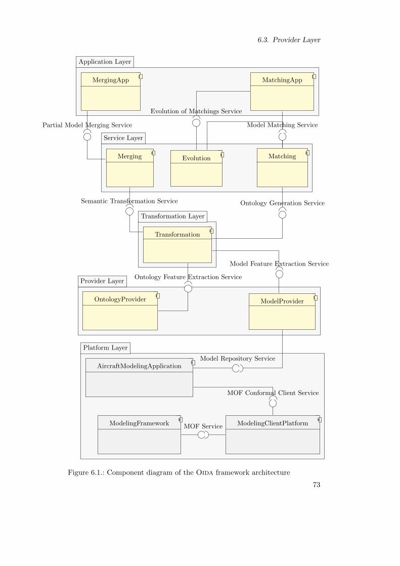
6.3. Provider Layer
Application Layer
Service Layer
Transformation Layer
Provider Layer
Platform Layer
MatchingAppMatchingAppMergingAppMergingApp
MergingMerging MatchingMatchingEvolutionEvolution
TransformationTransformation
ModelProviderModelProviderOntologyProviderOntologyProvider
AircraftModelingApplicationAircraftModelingApplication
ModelingClientPlatformModelingClientPlatformModelingFrameworkModelingFramework MOF Service
MOF Conformal Client Service
Partial Model Merging Service
Evolution of Matchings Service
Model Matching Service
Semantic Transformation Service Ontology Generation Service
Model Feature Extraction Service
Ontology Feature Extraction Service
Model Repository Service
Figure 6.1.: Component diagram of the Oida framework architecture
73
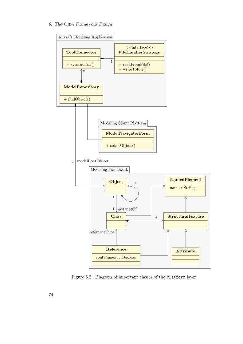
6. The Oida Framework Design
Aircraft Modeling Application
Modeling Client Platform
Modeling Framework
1
*
*
modelRootObject1
*
instanceOf1
referenceType
*
ModelRepository
+ findObject()
ToolConnector
+ synchronize()
<<interface>>FileHandlerStrategy
+ readFromFile()+ writeToFile()
ModelNavigatorForm
+ selectObject()
Object NamedElement
name : String
Class StructuralFeature
AttributeReference
containment : Boolean
Figure 6.2.: Diagram of important classes of the Platform layer
74
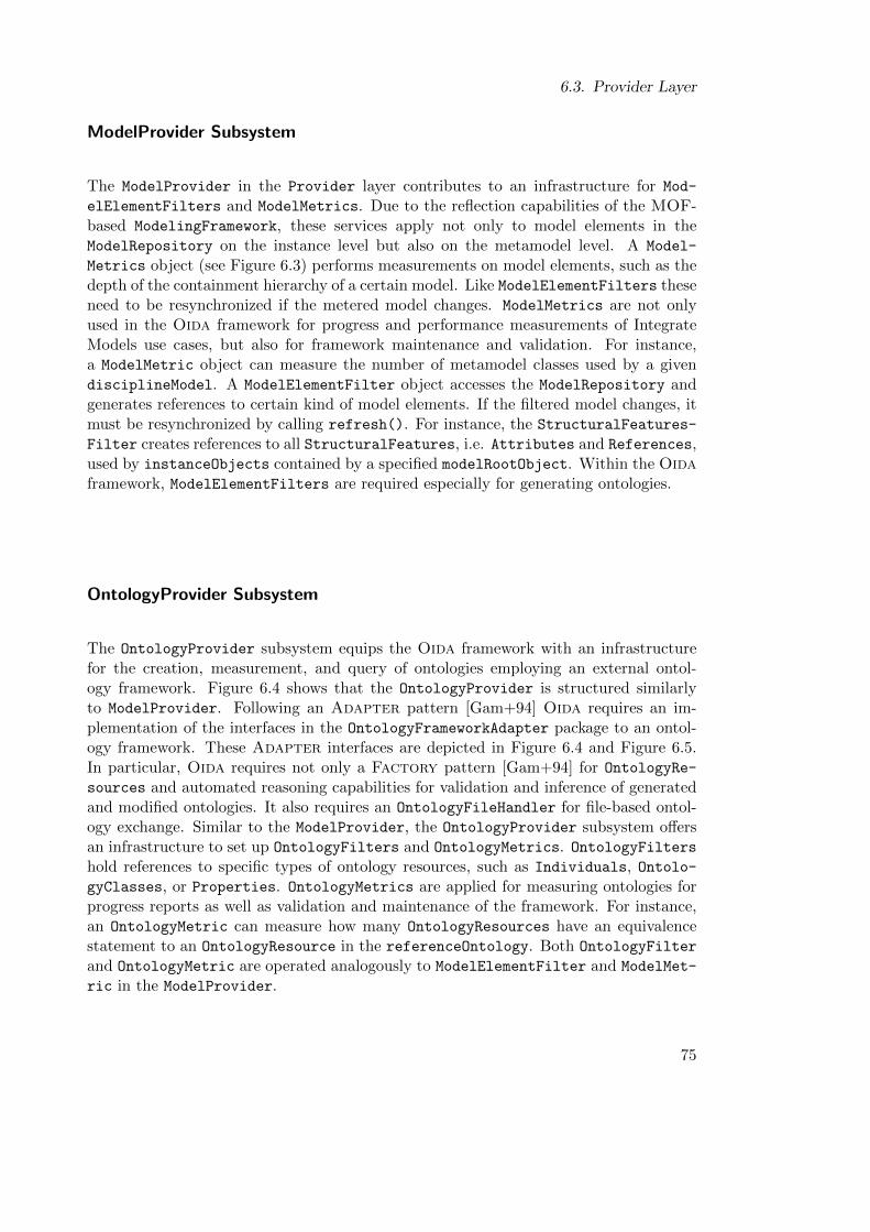
6.3. Provider Layer
ModelProvider Subsystem
The ModelProvider in the Provider layer contributes to an infrastructure for Mod-
elElementFilters and ModelMetrics. Due to the reflection capabilities of the MOF-based ModelingFramework, these services apply not only to model elements in theModelRepository on the instance level but also on the metamodel level. A Model-
Metrics object (see Figure 6.3) performs measurements on model elements, such as thedepth of the containment hierarchy of a certain model. Like ModelElementFilters theseneed to be resynchronized if the metered model changes. ModelMetrics are not onlyused in the Oida framework for progress and performance measurements of IntegrateModels use cases, but also for framework maintenance and validation. For instance,a ModelMetric object can measure the number of metamodel classes used by a givendisciplineModel. A ModelElementFilter object accesses the ModelRepository andgenerates references to certain kind of model elements. If the filtered model changes, itmust be resynchronized by calling refresh(). For instance, the StructuralFeatures-
Filter creates references to all StructuralFeatures, i.e. Attributes and References,used by instanceObjects contained by a specified modelRootObject. Within the Oidaframework, ModelElementFilters are required especially for generating ontologies.
OntologyProvider Subsystem
The OntologyProvider subsystem equips the Oida framework with an infrastructurefor the creation, measurement, and query of ontologies employing an external ontol-ogy framework. Figure 6.4 shows that the OntologyProvider is structured similarlyto ModelProvider. Following an Adapter pattern [Gam+94] Oida requires an im-plementation of the interfaces in the OntologyFrameworkAdapter package to an ontol-ogy framework. These Adapter interfaces are depicted in Figure 6.4 and Figure 6.5.In particular, Oida requires not only a Factory pattern [Gam+94] for OntologyRe-
sources and automated reasoning capabilities for validation and inference of generatedand modified ontologies. It also requires an OntologyFileHandler for file-based ontol-ogy exchange. Similar to the ModelProvider, the OntologyProvider subsystem offersan infrastructure to set up OntologyFilters and OntologyMetrics. OntologyFiltershold references to specific types of ontology resources, such as Individuals, Ontolo-gyClasses, or Properties. OntologyMetrics are applied for measuring ontologies forprogress reports as well as validation and maintenance of the framework. For instance,an OntologyMetric can measure how many OntologyResources have an equivalencestatement to an OntologyResource in the referenceOntology. Both OntologyFilter
and OntologyMetric are operated analogously to ModelElementFilter and ModelMet-
ric in the ModelProvider.
75
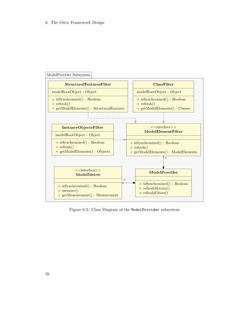
6. The Oida Framework Design
ModelProvider Subsystem
*
*
ModelProvider
+ isSynchronized() : Boolean+ refreshMetrics()+ refreshFilters()
<<interface>>ModelElementFilter
+ isSynchronized() : Boolean+ refresh()+ getModelElements() : ModelElements
<<interface>>ModelMetric
+ isSynchronized() : Boolean+ measure()+ getMeasurement() : Measurement
StructuralFeaturesFilter
modelRootObject : Object
+ isSynchronized() : Boolean+ refresh()+ getModelElements() : StructuralFeatures
InstanceObjectsFilter
modelRootObject : Object
+ isSynchronized() : Boolean+ refresh()+ getModelElements() : Objects
ClassFilter
modelRootObject : Object
+ isSynchronized() : Boolean+ refresh()+ getModelElements() : Classes
Figure 6.3.: Class Diagram of the ModelProvider subsystem
76
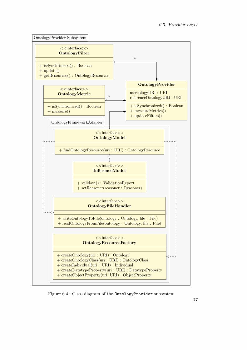
6.3. Provider Layer
OntologyProvider Subsystem
OntologyFrameworkAdapter
*
*
OntologyProvider
mereologyURI : URIreferenceOntologyURI : URI
+ isSynchronized() : Boolean+ measureMetrics()+ updateFilters()
<<interface>>OntologyFilter
+ isSynchrinized() : Boolean+ update()+ getResources() : OntologyResources
<<interface>>OntologyMetric
+ isSynchronized() : Boolean+ measure()
<<interface>>OntologyModel
+ findOntologyResource(uri : URI) : OntologyResource
<<interface>>InferenceModel
+ validate() : ValidationReport+ setReasoner(reasoner : Reasoner)
<<interface>>OntologyFileHandler
+ writeOntologyToFile(ontology : Ontology, file : File)+ readOntologyFromFile(ontology : Ontology, file : File)
<<interface>>OntologyResourceFactory
+ createOntology(uri : URI) : Ontology+ createOntologyClass(uri : URI) : OntologyClass+ createIndividual(uri : URI) : Individual+ createDatatypeProperty(uri : URI) : DatatypeProperty+ createObjectProperty(uri :URI) : ObjectProperty
Figure 6.4.: Class diagram of the OntologyProvider subsystem
77
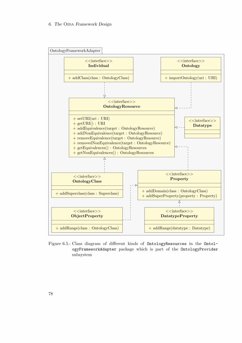
6. The Oida Framework Design
OntologyFrameworkAdapter
<<interface>>OntologyResource
+ setURI(uri : URI)+ getURI() : URI+ addEquivalence(target : OntologyResource)+ addNonEquivalence(target : OntologyResource)+ removeEquivalence(target : OntologyResource)+ removedNonEquivalence(target : OntologyResource)+ getEquivalences() : OntologyResources+ getNonEquivalences() : OntologyResources
<<interface>>OntologyClass
+ addSuperclass(class : Superclass)
<<interface>>Property
+ addDomain(class : OntologyClass)+ addSuperProperty(property : Property)
<<interface>>ObjectProperty
+ addRange(class : OntologyClass)
<<interface>>DatatypeProperty
+ addRange(datatype : Datatype)
<<interface>>Individual
+ addClass(class : OntologyClass)
<<interface>>Datatype
<<interface>>Ontology
+ importOntology(uri : URI)
Figure 6.5.: Class diagram of different kinds of OntologyResources in the Ontol-
ogyFrameworkAdapter package which is part of the OntologyProvider
subsystem
78
6.4. Transformation Layer
6.4. Transformation Layer
The Transformation layer establishes couplings between different disciplineModels
and mediates between ontologies and models. This role is realized by the Transforma-
tion subsystem.
Transformation Subsystem
The Transformation subsystem provides the Semantic Transformation Service whichcomprises not only semantic model transformation but also the capability to generateontologies and metamodels. According to Figure 6.6, TransformationControl holdsa set of Transformations which can be interdependent. In order to execute them inthe right order, every implementation of a Transformation must determine whether itis executable and whether both the source and the target of the Transformation aresynchronized. In general, source and target model are synchronized when the Transfor-mation has been performed and neither its source nor its target have been changed sincethen. Given that TransformationControl holds instances of ModelTransformation
and MetamodelGenerator and startTransformations() is called, Transformation-
Control executes all Transformations whose isExecuteable() method returns true.MetamodelGenerator will be executed as it does not depend on any other Transfor-
mation. ModelTransformation requires the referenceMetamodel which is generatedby the MetamodelGenerator as target metamodel. An implementation of isExecute-
able() will return the value of isSynchronized() of MetamodelGenerator. Whenthe MetamodelGenerator has finished the generation of the Metamodel and this valuechanges to true, the TransformationControl executes the ModelTransformation. TheTransformationControl references a ModelProvider and an OntologyProvider for theTransformations to operate on.
For instance, the MetamodelGenerator requires the referenceOntology from theOntologyProvider in order to generate the referenceMetamodel in the ModelProvi-
der. Thereby, it registers mappings between ontology and model data types. Con-versely, the OntologyGenerator requires a disciplineModel from the ModelProvider
and generates a disciplineOntology in the OntologyProvider. During the genera-tion process it employs the Renamer which must generate an unambiguous name from adisciplineObject identifier. This Renamer can be adapted to the particular context ofa disciplineModel by a concrete RenamerStrategy. The Renamer can determine if aconcrete RenamerStrategy is unambiguous for a given disciplineModel, which allowshigher layer clients of the Transformation subsystem to assess the applicability of aparticular strategy. Within the Transformation subsystem the Renamer is employed byStatementGenerators for generating ontology statements. For instance, an Ontology-
ClassGenerator extracts all Classes used in the disciplineModel by a ClassFilter
of the ModelProvider and generates appropriate OntologyClasses.
Both MetamodelGenerator and OntologyGenerator can operate as unidirectionaltransformations to facilitate the Integrate Models use cases. The ModelTransforma-
tion, however, must operate bidirectionally in order to facilitate the Partial Model
79
6. The Oida Framework Design
Merge capability which requires not only the transformation of domainModels to acommon referenceMetamodel, but also the propagation of changes in the reference-
ConformModels back to the domainModels. Therefore, the ModelTransformation cre-ates ObjectMappings between disciplineObjects and referenceObjects at the modellevel. Furthermore, every object mapping holds a mapping of the respective discipline-Class and referenceClass and its StructuralFeatures provided by EMF. Thesemappings are entirely based on the equivalence statements in the disciplineOntology.
6.5. Service Layer
The Service layer contains components which address specific capabilities such as ModelMatching, Partial Model Merge, and Co-Evolution. The layer is partitioned into appro-priate subsystems, which provide infrastructure and decision support capabilities forhigher level subsystems with user interfaces. Whereas the Matching and Evolution
subsystems have the similar purpose of matching artifacts, the Matching subsystemfocuses on matching concurrent artifacts, whereas Evolution matches old and newerversions of ontologies.
Matching Subsystem
The Matching subsystem must facilitate the Semantic Matching of two discipline-
Models by the semi-automated matching of a disciplineOntology generated from adisciplineModel to a referenceOntology. The input of this subsystem is an ontologywhich has been derived from a domain specific model, and a reference ontology whichinitially can be empty. The Matching subsystem provides a framework which createsstatements in derivedOntology to the referenceOntology whereas the referenceOn-
tology is extended by new referenceConcepts employing the OntologyProvider.The creation of equivalence relationships is challenging especially with respect to the
user acceptance. Matching disciplineOntology and referenceOntology in the givenproblem context requires a complex algorithm that is hard for Model Owners to followwhile the quality of the result cannot be guaranteed. However, there are simple matchingalgorithms and the Reasoner which can contribute to the manual creation of equivalencerelations by recommending and validating partial solutions.
The Matching subsystem is designed according to the Blackboard pattern [BHS07].The Blackboard holds a reference to an OntologyProvider which contains not only theconcepts in the disciplineOntology which have been derived from a disciplineModel,but also the equivalence statements which are created by the matching subsystem. TheMatchingControl realizes the Semantic Matching service which enables other subsys-tems to contribute new KnowledgeSources and types of intermediate solutions to theBlackboard.
Based on the assumption that automated algorithms can only propose Equivalence-
Hypotheses which eventually need to be confirmed by the Model Owner, the Black-
board holds intermediate solutions as hypotheses which are generated by a Hypothesis-
Generator. An EquivalenceHypothesis references a pair of OntologyResources which
80
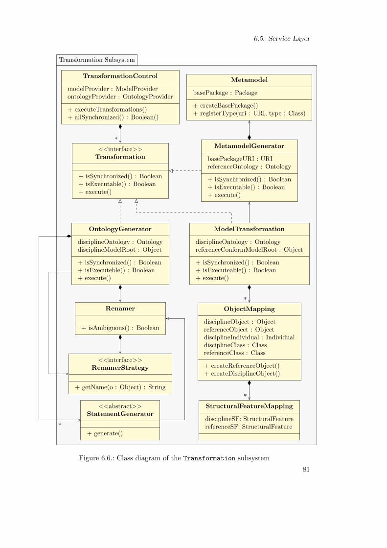
6.5. Service Layer
Transformation Subsystem
*
*
*
*
TransformationControl
modelProvider : ModelProviderontologyProvider : OntologyProvider
+ executeTransformations()+ allSynchronized() : Boolean()
MetamodelGenerator
basePackageURI : URIreferenceOntology : Ontology
+ isSynchronized() : Boolean+ isExecutable() : Boolean+ execute()
<<interface>>Transformation
+ isSynchronized() : Boolean+ isExecutable() : Boolean+ execute()
Metamodel
basePackage : Package
+ createBasePackage()+ registerType(uri : URI, type : Class)
OntologyGenerator
disciplineOntology : OntologydisciplineModelRoot : Object
+ isSynchronized() : Boolean+ isExecuteble() : Boolean+ execute()
ModelTransformation
disciplineOntology : OntologyreferenceConformModelRoot : Object
+ isSynchronized() : Boolean+ isExecuteable() : Boolean+ execute()
Renamer
+ isAmbiguous() : Boolean
ObjectMapping
disciplineObject : ObjectreferenceObject : ObjectdisciplineIndividual : IndividualdisciplineClass : ClassreferenceClass : Class
+ createReferenceObject()+ createDisciplineObject()
<<interface>>RenamerStrategy
+ getName(o : Object) : String
<<abstract>>StatementGenerator
+ generate()
StructuralFeatureMapping
disciplineSF: StructuralFeaturereferenceSF: StructuralFeature
Figure 6.6.: Class diagram of the Transformation subsystem
81
6. The Oida Framework Design
are hypothetically equivalent as well as the URI of the HypothesisGenerator and Hypo-
thesisReviewer. HypothesisReviewer and HypothesisValidator are provided withthe following review and validation methods: By calling approve() the value of ap-
proved is set to true. Conversely, decline() changes the value, approved is changedto false. Both approve() and decline() set the value of reviewed to true whichincreases the status of an EquivalenceHypothesis from the Proposed Equivalence Hy-pothesis level to the Reviewed Hypothesis level as shown in Figure 6.8. By callingcommit(), the EquivalenceHypothesis is added as a new equivalence or nonequiva-lence statement to the disciplineOntology depending on the value of the approved
attribute. By calling discard() the EquivalenceHypothesis is taken from the black-board. If an equivalence statement is created, the underlying EquivalenceHypothesis isnot deleted from the blackboard. Such an equivalence statement can be removed from thedisciplineOntology by calling reconsider(). Generally, an EquivalenceReviewer isoperated directly by the Model Owner. As the Matching subsystem does not have a userinterface it does not provide concrete EquivalenceReviewers.
Figure 6.8 illustrates the different levels of solutions and the two kinds of Knowledge-Sources which contribute to the Blackboard. Automated HypothesisGenerators suchas the NameEquivalenceFinder and the StructureEquivalenceFinder automaticallycontribute to the hypothesis level. In particular, The NameEquivalenceFinder uses theidentifiers of the ontology resources as input. It creates EquivalenceHypotheses if tworesources are equal. The StructureEquivalenceFinder uses all existing equivalencestatements and EquivalenceHypotheses to create new EquivalenceHypotheses if twoOntologyResources have equivalent Properties.
The Matching subsystem also provides the SemanticValidator as implementation ofthe HypothesisValidator interface. As such, the SemanticValidator is an exampleof an automated HypothesisValidator. It determines whether equivalence statementsresult in a semantically consistent ontology. A SemanticValidator object uses an In-
ferenceModel provided by the OntologyProvider subsystem. If the Reasoner of thisInferenceModel determines inconsistent statements, the SemanticValidator evaluatesthe validation report of the Reasoner. If a particular equivalence statement causesan inconsistency, the SemanticValidator removes the equivalence statements from theontology and puts the equivalence relation as a proposed and unapproved Equivalence-
Hypothesis on the Blackboard for reconsideration. If the Reasoner determines that aparticular equivalence statement is consistent with the existing ontology it removes therespective equivalence statement by calling the discard() method.
Merging Subsystem
The PartialModelMerge service of the Merging subsystem is provided and initiated byMergingControl. For the Merge Models Partially use case MergingControl requires areference to the source and target disciplineModels which both need to be transformedto a common MetaModel. Therefore, the MergingControl requests the Semantic Model
Transformation service from the Transformation subsystem. This service is configured
82
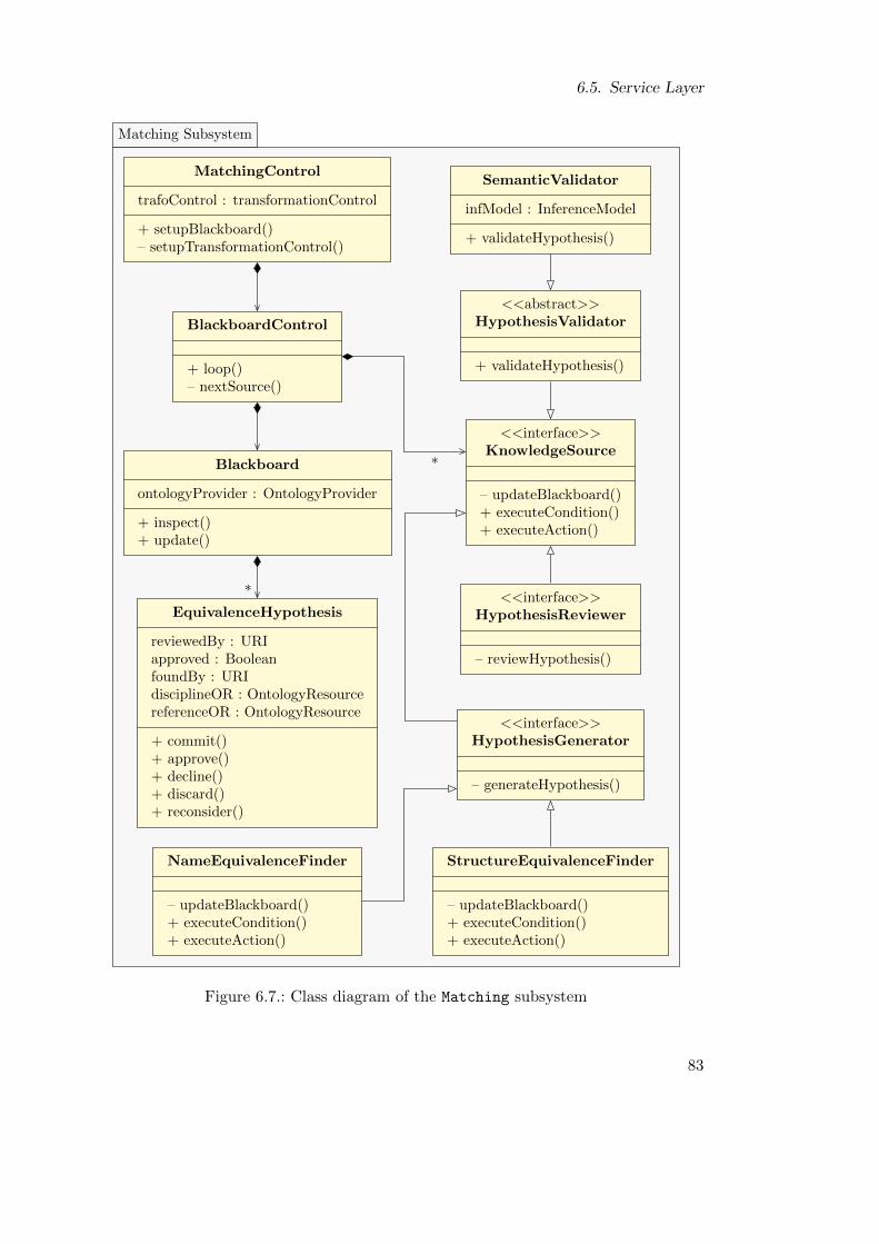
6.5. Service Layer
Matching Subsystem
*
*
MatchingControl
trafoControl : transformationControl
+ setupBlackboard()– setupTransformationControl()
BlackboardControl
+ loop()– nextSource()
<<abstract>>HypothesisValidator
+ validateHypothesis()
SemanticValidator
infModel : InferenceModel
+ validateHypothesis()
Blackboard
ontologyProvider : OntologyProvider
+ inspect()+ update()
<<interface>>KnowledgeSource
– updateBlackboard()+ executeCondition()+ executeAction()
<<interface>>HypothesisReviewer
– reviewHypothesis()
<<interface>>HypothesisGenerator
– generateHypothesis()
EquivalenceHypothesis
reviewedBy : URIapproved : BooleanfoundBy : URIdisciplineOR : OntologyResourcereferenceOR : OntologyResource
+ commit()+ approve()+ decline()+ discard()+ reconsider()
NameEquivalenceFinder
– updateBlackboard()+ executeCondition()+ executeAction()
StructureEquivalenceFinder
– updateBlackboard()+ executeCondition()+ executeAction()
Figure 6.7.: Class diagram of the Matching subsystem
83
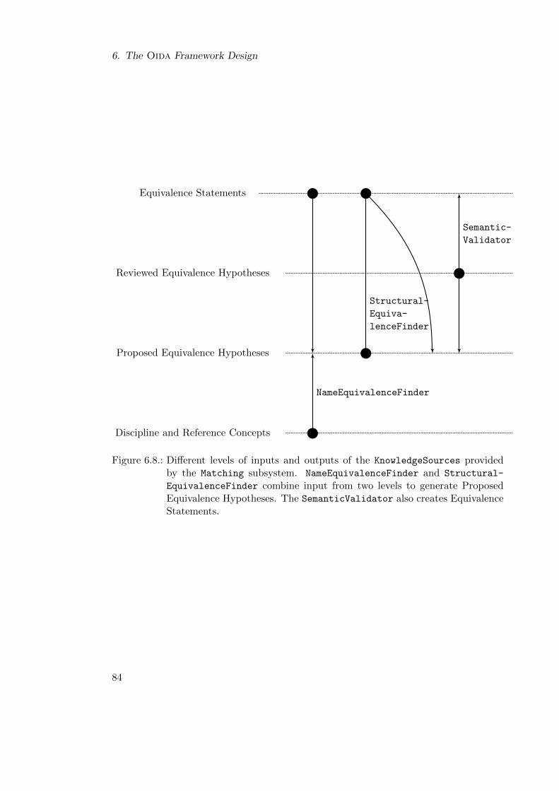
6. The Oida Framework Design
Equivalence Statements
Reviewed Equivalence Hypotheses
Proposed Equivalence Hypotheses
Discipline and Reference Concepts
Structural-
Equiva-
lenceFinder
Semantic-
Validator
NameEquivalenceFinder
Figure 6.8.: Different levels of inputs and outputs of the KnowledgeSources providedby the Matching subsystem. NameEquivalenceFinder and Structural-
EquivalenceFinder combine input from two levels to generate ProposedEquivalence Hypotheses. The SemanticValidator also creates EquivalenceStatements.
84
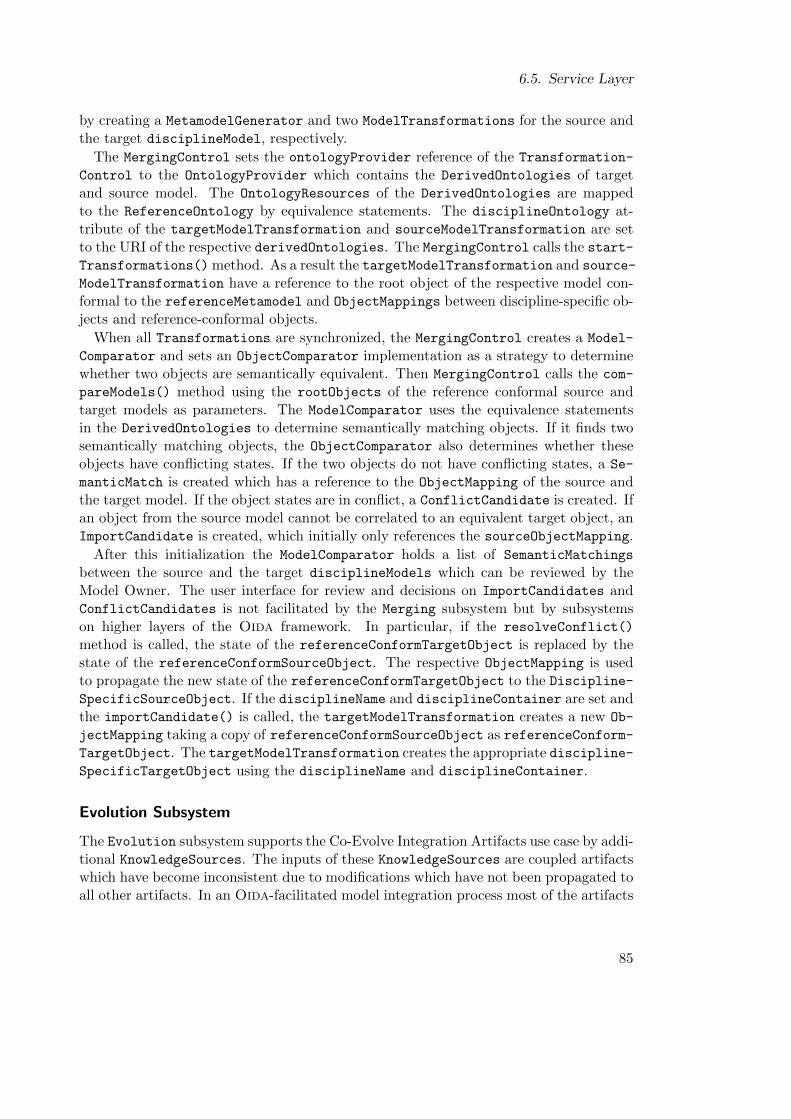
6.5. Service Layer
by creating a MetamodelGenerator and two ModelTransformations for the source andthe target disciplineModel, respectively.
The MergingControl sets the ontologyProvider reference of the Transformation-
Control to the OntologyProvider which contains the DerivedOntologies of targetand source model. The OntologyResources of the DerivedOntologies are mappedto the ReferenceOntology by equivalence statements. The disciplineOntology at-tribute of the targetModelTransformation and sourceModelTransformation are setto the URI of the respective derivedOntologies. The MergingControl calls the start-Transformations() method. As a result the targetModelTransformation and source-
ModelTransformation have a reference to the root object of the respective model con-formal to the referenceMetamodel and ObjectMappings between discipline-specific ob-jects and reference-conformal objects.
When all Transformations are synchronized, the MergingControl creates a Model-
Comparator and sets an ObjectComparator implementation as a strategy to determinewhether two objects are semantically equivalent. Then MergingControl calls the com-
pareModels() method using the rootObjects of the reference conformal source andtarget models as parameters. The ModelComparator uses the equivalence statementsin the DerivedOntologies to determine semantically matching objects. If it finds twosemantically matching objects, the ObjectComparator also determines whether theseobjects have conflicting states. If the two objects do not have conflicting states, a Se-
manticMatch is created which has a reference to the ObjectMapping of the source andthe target model. If the object states are in conflict, a ConflictCandidate is created. Ifan object from the source model cannot be correlated to an equivalent target object, anImportCandidate is created, which initially only references the sourceObjectMapping.
After this initialization the ModelComparator holds a list of SemanticMatchings
between the source and the target disciplineModels which can be reviewed by theModel Owner. The user interface for review and decisions on ImportCandidates andConflictCandidates is not facilitated by the Merging subsystem but by subsystemson higher layers of the Oida framework. In particular, if the resolveConflict()
method is called, the state of the referenceConformTargetObject is replaced by thestate of the referenceConformSourceObject. The respective ObjectMapping is usedto propagate the new state of the referenceConformTargetObject to the Discipline-SpecificSourceObject. If the disciplineName and disciplineContainer are set andthe importCandidate() is called, the targetModelTransformation creates a new Ob-
jectMapping taking a copy of referenceConformSourceObject as referenceConform-TargetObject. The targetModelTransformation creates the appropriate discipline-SpecificTargetObject using the disciplineName and disciplineContainer.
Evolution Subsystem
The Evolution subsystem supports the Co-Evolve Integration Artifacts use case by addi-tional KnowledgeSources. The inputs of these KnowledgeSources are coupled artifactswhich have become inconsistent due to modifications which have not been propagated toall other artifacts. In an Oida-facilitated model integration process most of the artifacts
85
6. The Oida Framework Design
Merging subsystem
*
MergingControl
trafoControl : TransformationControlmetamodelGenerator : MetamodelGeneratorsourceTrafo : ModelTransformationtargetTrafo : ModelTransformation
– initiateModelComparator()– setUpModelTramsformations()+ transformModelsToReference()+ carryOutUserReview()
ModelComparator
+ compareModels(sRoot : Object, tRoot : Object)
<<interface>>ObjectComparator
+ isEqual(o1 : Object, o2 : Object)
SemanticMatch
reviewedBy : URIcomment : StringsourceMapping : ObjectMappingtargetMapping : ObjectMapping
+ confirm()+ report()
ImportCandidate
disciplineName : StringdisciplineContainer : Object
+ importCandidate()
ConflictCandidate
+ resolveConflict()
Figure 6.9.: Class diagram of the Merging Subsystem
86
6.6. Application Layer
are generated. Only the equivalence statements need to be created interactively. There-fore, the KnowledgeSources of the Evolution subsystem are focused on the migrationof previously approved equivalence statements.
The Evolution subsystem supports two scenarios. In the first scenario the modi-fications on the artifacts are recorded. An algorithm evaluates the modifications andperforms appropriate modifications on the coupled artifacts to re-establish consistency.In the second scenario the modifications which led to an inconsistency are unknown. Inthis case, the inconsistencies must be detected and resolved by a heuristic which doesnot guarantee results, or that any results will be unambiguous.
In both cases the previous version of the disciplineOntology and the reference-
Ontology can be loaded into the OntologyModel of the OntologyProvider held by theBlackboard. Furthermore, it is assumed that available modifications on artifacts areexpressed as statements in the OntologyModel.
As illustrated in Figure 6.10, the Evolution subsystem provides an Evolution-
Control and the two KnowledgeResources: EvolutionAlgorithm and Evolution-
Heuristic. EvolutionControl manages the availability of previous equivalence state-ments and known modifications as basic input of the Blackboard. Figure 6.11 illustratesthe KnowledgeSources implementing the EvolutionAlgorithm and the Evolution-
Heuristic interface. The EvolutionAlgorithm evaluates known modifications and re-vises equivalence statements accordingly. The algorithmic character of this Knowledge-Source implies its results are unambiguous. Therefore, an EvolutionAlgorithm gener-ates automatically approved EquivalenceHypotheses. An EvolutionHeuristic, how-ever, evaluates both existing disciplineConcepts and referenceConcepts as wellas previous equivalenceMappings and applies a heuristic in order to adjust them tothe new version. Depending on the result of the heuristic an implementation of theEvolutionHeuristic can produce approved or unapproved EquivalenceHypotheses.
6.6. Application Layer
The Application Layer provides user interfaces for the Model Matching and PartialModel Merge capabilities. Like the other components of the Oida framework, the user
interface components are integrated into the modeling environment and exhibit afamiliar look-and-feel for the aircraft modeler in order to ensure that the user experiencesthe use cases of ontology-based model integration as extensions of his aircraft designenvironment rather than as a separate application.
MatchingApp Application
The MatchingApp application enables the Model Owner to match a given discipline-
Model to a referenceOntology by declaring equivalence relationships between disci-pline and reference concepts employing the services of the Matching subsystem. Fig-ure 6.13 illustrates how the MatchingApp initializes the Blackboard in the Matching
subsystem setting up the TransformationControl and the KnowledgeSources. The
87
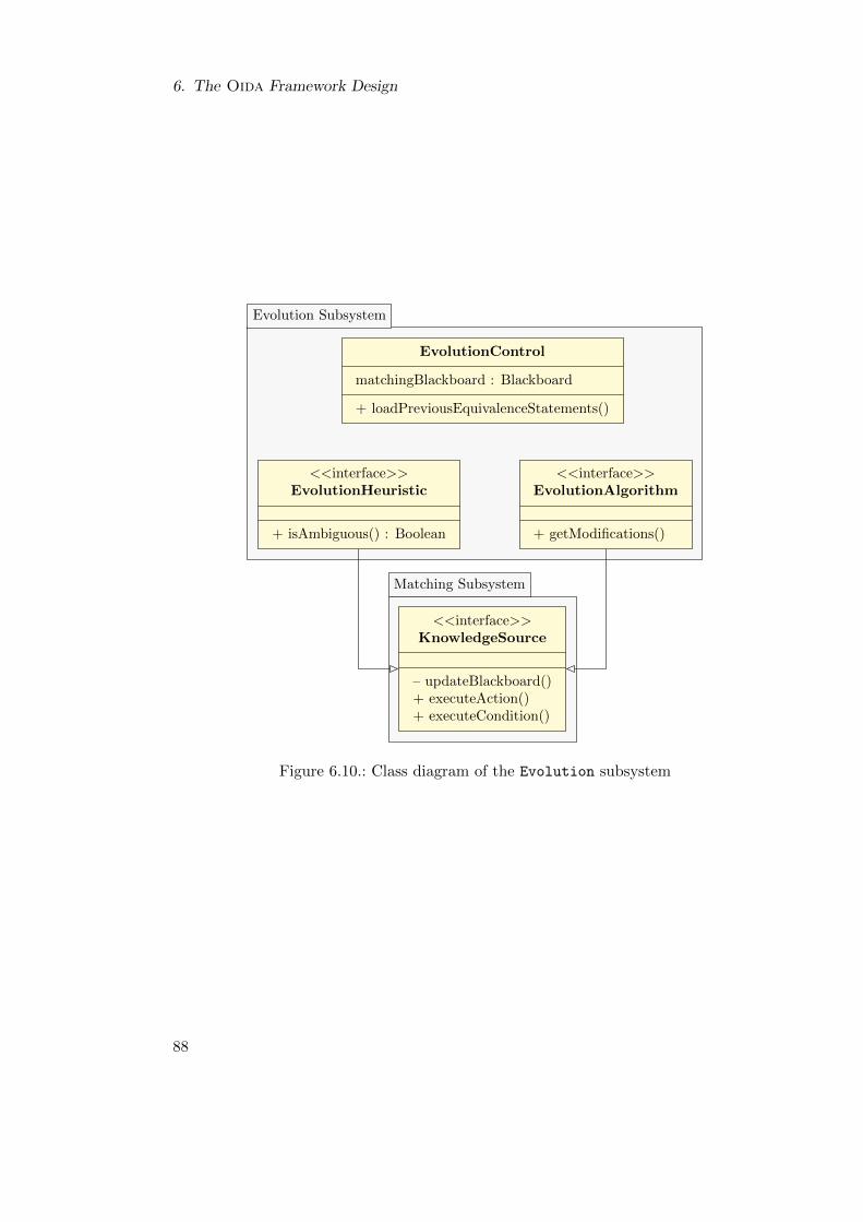
6. The Oida Framework Design
Evolution Subsystem
Matching Subsystem
EvolutionControl
matchingBlackboard : Blackboard
+ loadPreviousEquivalenceStatements()
<<interface>>EvolutionAlgorithm
+ getModifications()
<<interface>>EvolutionHeuristic
+ isAmbiguous() : Boolean
<<interface>>KnowledgeSource
– updateBlackboard()+ executeAction()+ executeCondition()
Figure 6.10.: Class diagram of the Evolution subsystem
88
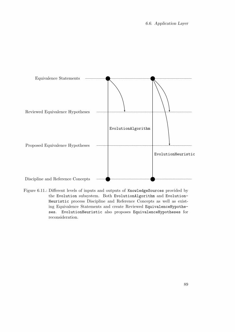
6.6. Application Layer
Equivalence Statements
Reviewed Equivalence Hypotheses
Proposed Equivalence Hypotheses
Discipline and Reference Concepts
EvolutionAlgorithm
EvolutionHeuristic
Figure 6.11.: Different levels of inputs and outputs of KnowledgeSources provided bythe Evolution subsystem. Both EvolutionAlgorithm and Evolution-
Heuristic process Discipline and Reference Concepts as well as exist-ing Equivalence Statements and create Reviewed EquivalenceHypothe-
ses. EvolutionHeuristic also proposes EquivalenceHypotheses forreconsideration.
89
6. The Oida Framework Design
TransformationControl is required to generate the input for the Matching subsys-tem, i.e. disciplineOntology derived from a given disciplineModel. Additionally, itadds interactive KnowledgeSources such as the ManualEquivalenceGenerator and theEquivalenceReviewForm. The ManualEquivalenceValidator provides a user interfacewhich displays EquivalenceHypotheses on the Blackboard and can receive and carryout the manual review of these EquivalenceHypotheses by the Model Owner.
The MatchingApp also provides the BlackboardControlForm for the control of theBlackboard. It allows the user to adjust the behavior of the nextSource() methodby the manual activation and deactivation of particular KnowledgeSources. Further-more, it also provides a report on the progress of the Match Models process. Af-ter the initialization, MatchingApp triggers the generation of the disciplineOntology
and calls the loop() method of the BlackboardControl to start the interactive semi-automated matching process. It also saves the results when the user determines that thedisciplineOntology is sufficiently well matched with the referenceOntology.
Figure 6.12 illustrates how these KnowledgeSources contribute to the different so-lution levels held by the Blackboard. The ManualEquivalenceGenerator provides auser interface which allows the Model Owner to navigate the derivedOntology and thereferenceOntology and select pairs of OntologyResources in order to create Equiva-
lenceHypotheses manually. If the Model Owner cannot find an adequate reference con-cept, the ManualEquivalenceGenerator provides a ReferenceCreatorDialog whichthe Model Owner can use to add new referenceResources to the referenceOntology.
The ManualEquivalenceReviewer provides a user interface displaying the availableEquivalenceHypotheses to the Model Owner. The Model Owner reviews the hypothe-ses by either approving, declining, or discarding them. As a user interface equippedKnowledgeSource, the ManualEquivalenceReviewer contributes with these user deci-sions to the Blackboard of the Matching subsystem.
MergingApp Application
The MergingApp application enables the Model Owner to review the SemanticMatches,ConflictCandidates, and ImportCandidates. Figure 6.14 shows the classes providedby the MergingApp subsystem. The MergingApp uses the SemanticMatchReview bothfor reviewing SemanticMatchings and ConflictCandidates. The ImportCandidate-
CompletionForm is a specialization of the SemanticMatchReview which allows the ModelOwner to complete the information required for importing the object by choosing adiscipline-specific name and container object for the ImportCandidate object. For theselection of the container, the ContainerNavigatorForm, a specialized ModelNaviga-
torForm of the ModelingClientPlatform is used that only displays container objectsof the targetDisciplineModel. During the Merge Models Partially use case the userinterface displays a report on the progress of the review. As the ModelProvider subsys-tem works directly on the targetDisciplineModel the conflict resolution and importdecisions are carried out instantly. However, when the user closes the MergingApp,review comments and newly imported equivalence statements are stored in the target-
DisciplineOntology.
90
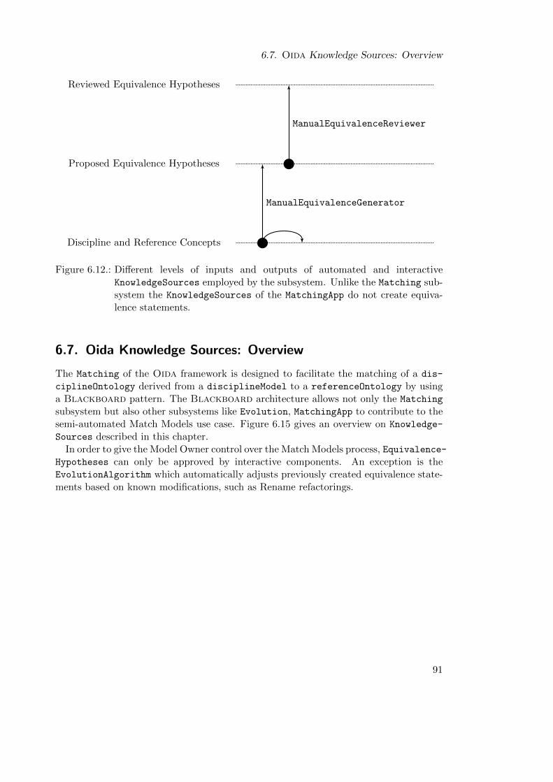
6.7. Oida Knowledge Sources: Overview
Reviewed Equivalence Hypotheses
Proposed Equivalence Hypotheses
Discipline and Reference Concepts
ManualEquivalenceReviewer
ManualEquivalenceGenerator
Figure 6.12.: Different levels of inputs and outputs of automated and interactiveKnowledgeSources employed by the subsystem. Unlike the Matching sub-system the KnowledgeSources of the MatchingApp do not create equiva-lence statements.
6.7. Oida Knowledge Sources: Overview
The Matching of the Oida framework is designed to facilitate the matching of a dis-
ciplineOntology derived from a disciplineModel to a referenceOntology by usinga Blackboard pattern. The Blackboard architecture allows not only the Matching
subsystem but also other subsystems like Evolution, MatchingApp to contribute to thesemi-automated Match Models use case. Figure 6.15 gives an overview on Knowledge-
Sources described in this chapter.In order to give the Model Owner control over the Match Models process, Equivalence-
Hypotheses can only be approved by interactive components. An exception is theEvolutionAlgorithm which automatically adjusts previously created equivalence state-ments based on known modifications, such as Rename refactorings.
91
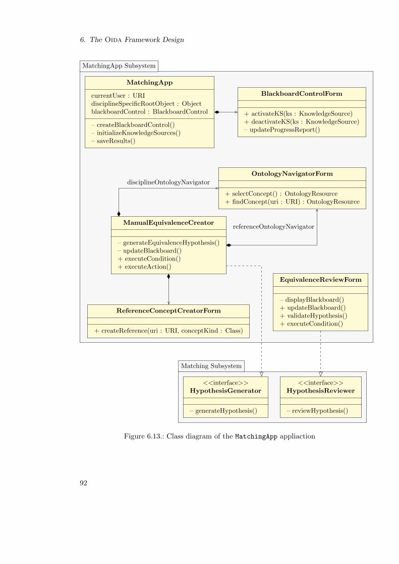
6. The Oida Framework Design
MatchingApp Subsystem
Matching Subsystem
referenceOntologyNavigator
disciplineOntologyNavigator
MatchingApp
currentUser : URIdisciplineSpecificRootObject : ObjectblackboardControl : BlackboardControl
– createBlackboardControl()– initializeKnowledgeSources()– saveResults()
BlackboardControlForm
+ activateKS(ks : KnowledgeSource)+ deactivateKS(ks : KnowledgeSource)– updateProgressReport()
ReferenceConceptCreatorForm
+ createReference(uri : URI, conceptKind : Class)
EquivalenceReviewForm
– displayBlackboard()+ updateBlackboard()+ validateHypothesis()+ executeCondition()
OntologyNavigatorForm
+ selectConcept() : OntologyResource+ findConcept(uri : URI) : OntologyResource
ManualEquivalenceCreator
– generateEquivalenceHypothesis()– updateBlackboard()+ executeCondition()+ executeAction()
<<interface>>HypothesisReviewer
– reviewHypothesis()
<<interface>>HypothesisGenerator
– generateHypothesis()
Figure 6.13.: Class diagram of the MatchingApp appliaction
92
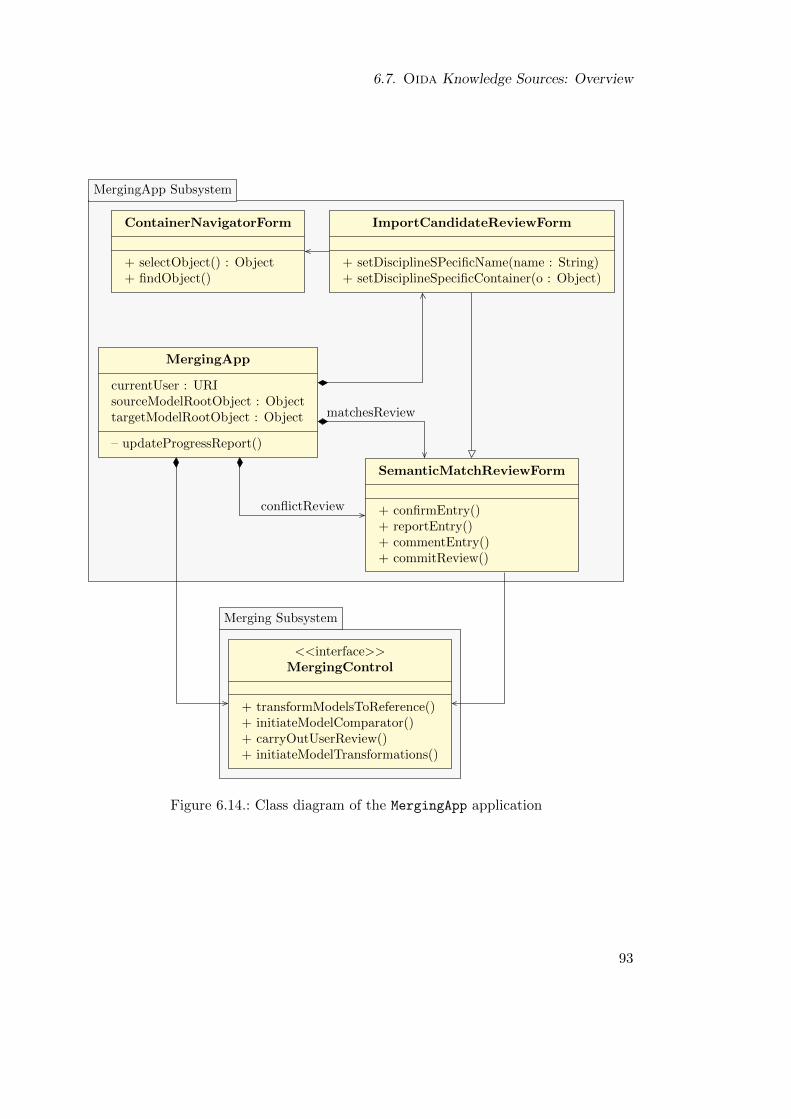
6.7. Oida Knowledge Sources: Overview
MergingApp Subsystem
Merging Subsystem
matchesReview
conflictReview
MergingApp
currentUser : URIsourceModelRootObject : ObjecttargetModelRootObject : Object
– updateProgressReport()
SemanticMatchReviewForm
+ confirmEntry()+ reportEntry()+ commentEntry()+ commitReview()
ImportCandidateReviewForm
+ setDisciplineSPecificName(name : String)+ setDisciplineSpecificContainer(o : Object)
ContainerNavigatorForm
+ selectObject() : Object+ findObject()
<<interface>>MergingControl
+ transformModelsToReference()+ initiateModelComparator()+ carryOutUserReview()+ initiateModelTransformations()
Figure 6.14.: Class diagram of the MergingApp application
93
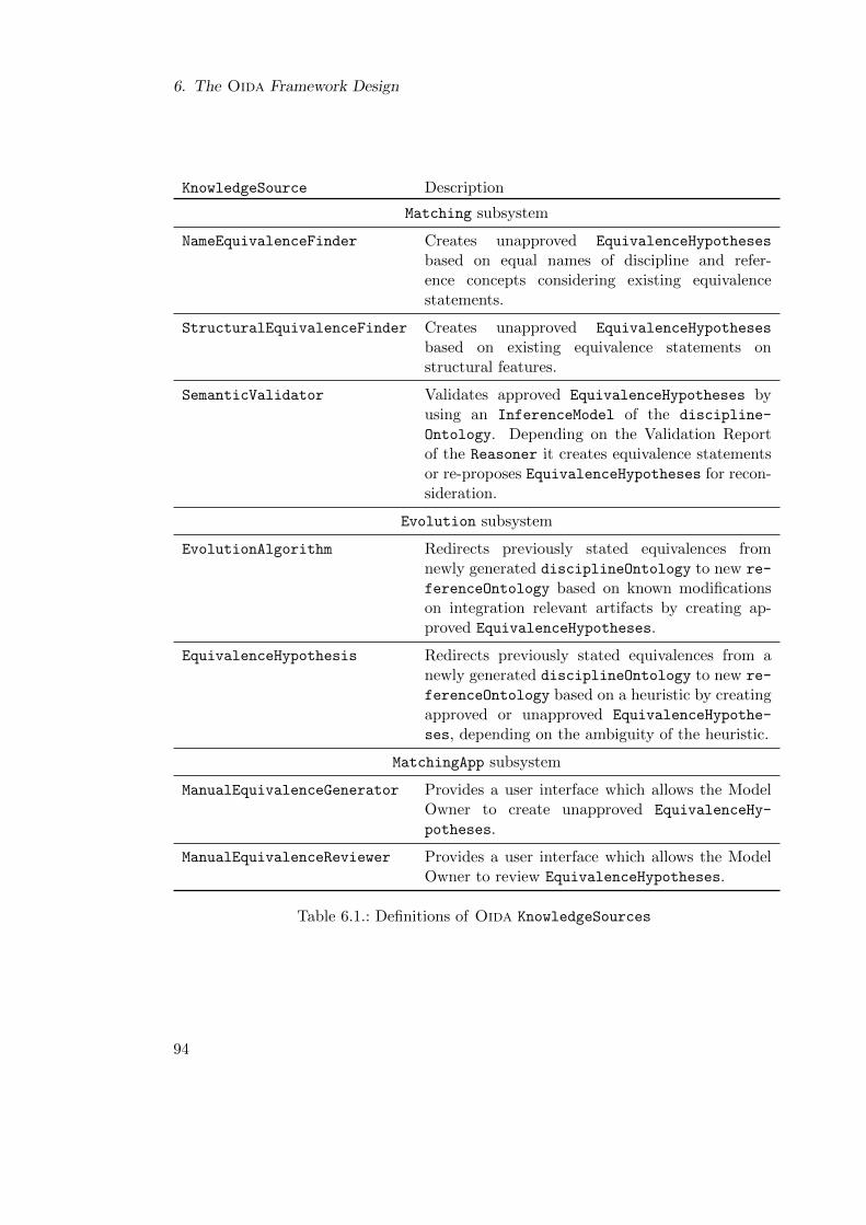
6. The Oida Framework Design
KnowledgeSource Description
Matching subsystem
NameEquivalenceFinder Creates unapproved EquivalenceHypotheses
based on equal names of discipline and refer-ence concepts considering existing equivalencestatements.
StructuralEquivalenceFinder Creates unapproved EquivalenceHypotheses
based on existing equivalence statements onstructural features.
SemanticValidator Validates approved EquivalenceHypotheses byusing an InferenceModel of the discipline-
Ontology. Depending on the Validation Reportof the Reasoner it creates equivalence statementsor re-proposes EquivalenceHypotheses for recon-sideration.
Evolution subsystem
EvolutionAlgorithm Redirects previously stated equivalences fromnewly generated disciplineOntology to new re-
ferenceOntology based on known modificationson integration relevant artifacts by creating ap-proved EquivalenceHypotheses.
EquivalenceHypothesis Redirects previously stated equivalences from anewly generated disciplineOntology to new re-
ferenceOntology based on a heuristic by creatingapproved or unapproved EquivalenceHypothe-
ses, depending on the ambiguity of the heuristic.
MatchingApp subsystem
ManualEquivalenceGenerator Provides a user interface which allows the ModelOwner to create unapproved EquivalenceHy-
potheses.
ManualEquivalenceReviewer Provides a user interface which allows the ModelOwner to review EquivalenceHypotheses.
Table 6.1.: Definitions of Oida KnowledgeSources
94
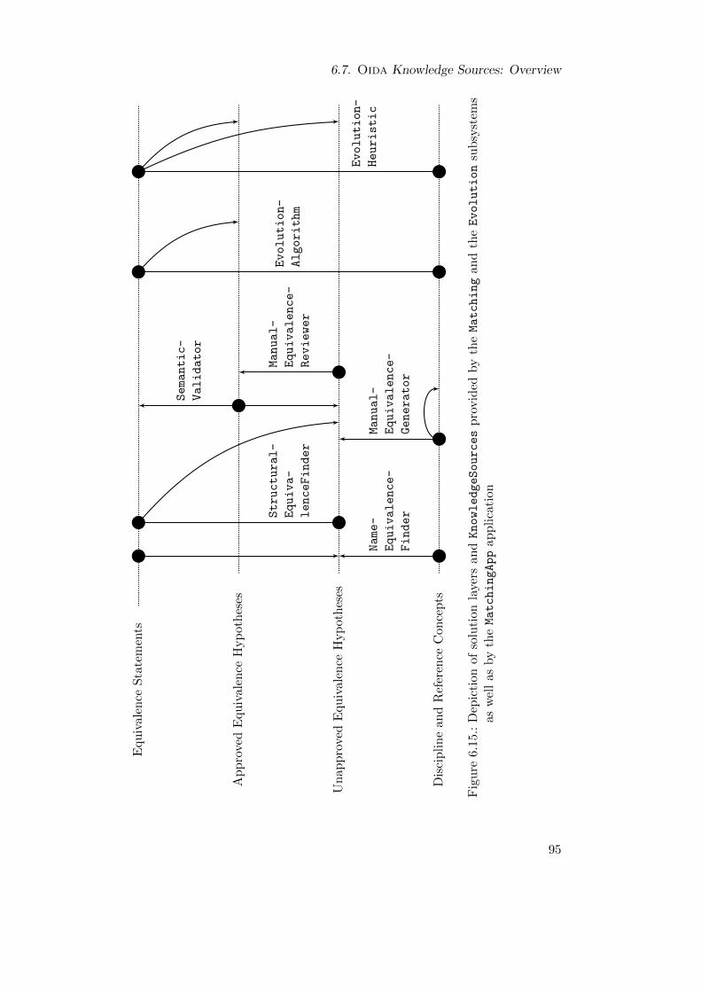
6.7. Oida Knowledge Sources: Overview
Equ
ival
ence
Sta
tem
ents
Ap
pro
ved
Equiv
alen
ceH
yp
oth
eses
Un
app
rove
dE
quiv
alen
ceH
yp
oth
eses
Dis
cip
lin
ean
dR
efer
ence
Con
cep
ts
Structural-
Equiva-
lenceFinder
Semantic-
Validator
Name-
Equivalence-
Finder
Manual-
Equivalence-
Reviewer
Manual-
Equivalence-
Generator
Evolution-
Algorithm
Evolution-
Heuristic
Fig
ure
6.1
5.:
Dep
icti
on
of
solu
tion
laye
rsan
dKnowledgeSources
pro
vid
edby
theMatching
and
theEvolution
sub
syst
ems
asw
ell
asby
theMatchingApp
app
lica
tion
95

7. Evaluation
The objective of this evaluation is to analyze the Oida framework in typical scenariosof ontology-based model integration regarding effectiveness, efficiency, and plausibilityof results from the perspective of typical users. In particular, the Oida framework isevaluated with regard to to the following criteria which are derived from the requirementsstated in Section 3.2:
• As the solution transfers the problem of model integration from the modelingtechnological space to the ontology technological space, the mapping from modelto ontology must be injective in order to guarantee that no relevant information islost in the transformation. In particular, the unambiguity of the RenamerStrategyof the transformation TMO must be validated.
• The Oida framework must demonstrate its capability to identify conflicts betweenthe discipline-specific sample models APD, APA, and Simcad. Furthermore,the Oida framework must demonstrate its capability to resolve conflicts usingthe Simcad sample model as Chief Engineering Model which overrides the othersample models.
• The Model Owners must perceive the Oida-facilitated interactive process of onto-logy-based model integration as efficient. From their point of view the results ofthe integration process must be plausible.
• The Oida framework must demonstrate its co-evolution capabilities, i.e. smallmodifications in artifacts such as source models, the reference ontology, or the Oidaimplementation, which have become coupled by performing ontology-based modelintegration, must require only small effort by the Model Owners to reestablishconsistency between these artifacts.
7.1. Evaluation Design
The evaluation is structured into four parts. In the first part, the effectiveness of themodel-to-ontology transformation as a critical capability of the Oida framework is eval-uated. The next three parts evaluate the Model Matching, Partial Model Merge, andCo-Evolution capabilities of the Oida framework.
The Oida framework explicitly addresses the domain context of aircraft conceptualdesign and the importance of efficiency and plausibility of results as perceived by theModel Owner. Therefore, the evaluation requires empirical evaluation strategies appro-priate for this domain context. Wohlin et al. [Woh+00] describe survey, case study, andexperiment as basic empirical strategies:
97
7. Evaluation
A survey draws a representative sample from a population. Quantitative and qualita-tive data are collected by questionnaires and interviews. The data are analyzed in orderto generalize the conclusion to the entire population. In empirical software engineering,surveys are typically used to gather data about the state, the opinion, or performanceof a population before or after a new software engineering method or tool is introduced.In contrast to a case study, a survey puts more emphasis on the population than on thespecific sample.
In a case study , a typical situation or project is analyzed in which a solution ormethod of interest is used. In a case study, measurements and analysis emphasize thepeculiarities of the particular case. However, the conclusions from case studies cannot begeneralized. In most case studies, comparative analysis is the most important methodto strengthen the validity of conclusions. In particular, comparative case studies areimportant to filter co-founding factors. For instance, the benefit of a new tool can beevaluated by a case study in which two groups have to perform the same task. The firstgroup uses the new tool exclusively while the second group uses a conventional tool. Ifthe performance of the first group is considerably better, the new tool is most likely therelevant factor for the success.
The objective of an experiment is to achieve statistically significant conclusions bysystematic and quantitative measurements and by treatments employing techniques likerandomization, balancing, and blocking. Randomization means that a sample is takenrandomly from a population in order to minimize bias. Balancing means that treatmentshave the same characteristics and reduce variations in the treatment setup to emphasizean effect of interest. Therefore, the number of variables is low compared to survey andcase study. Randomization also requires a larger population than a case study. Blockingmeans that factors which can lead to an effect which is not of interest are deliberatelyshut out during a treatment. Blocking and a high level of measurement control implythat the analysis of an experiment accumulates measurements over multiple treatments.Thereby, peculiar observations during a single treatment can be lost. Especially, ifrandomization is impractical, a quasi-experiment evaluation strategy can be applied. Inparticular, in a quasi-experiment the evaluation objects are not randomly assigned toevaluation subjects. Therefore, the results of a quasi-experiment have less statisticalsignificance than real experiments.
The context of the domain-specific ontology-based model integration poses constraintsfor the selection of an evaluation strategy. The population of domain experts in con-ceptual aircraft design is small compared with other expert groups in aircraft design.The APA model, which was used as a sample model during the development and theevaluation, was developed and operated by one person. The case that the population ofModel Owners consists of only one person for a particular model is common in the con-text of conceptual aircraft design. Furthermore, as mentioned in Chapter 1, the designfreedom and the number and range of characteristic variables of Integrate Models in thiscontext is high. For instance, each sample model has a different decomposition strategy.Furthermore, the APA and APD sample models have considerably more model objectsthan the Simcad sample model. If these sample models were used in experiments, bothkinds of differences would threaten the comparability of the results. Considering the
98
7.2. Empirical Studies
small population of adequate subjects, an evaluation strategy which requires a largenumber of subjects is not viable. Accordingly, with respect to the variety of character-istic parameters of the domain context, only typical situations can be evaluated whichdoes not allow for the generalization of the results to the overall field of conceptual air-craft design. Furthermore, the evaluation of the Oida framework is rather focused onthe demonstration of the viability of the solution rather than the generalization of theOida framework.
These constraints led to an evaluation design shown in Table 7.1. As the transforma-tion algorithm does not require user interaction, it was evaluated by an automated unittest which gave full control over the testing procedure. As the limited number of samplemodels did not allow strict randomization of input data, a quasi-experiment evaluationstrategy was applied. The Match Models and Merge Models Partially use cases wereevaluated in case studies with typical Model Owners such as Model User, Model De-veloper, and Model Adopter as evaluation subjects. The Ontology Owner was enactedby the observer. The essential components facilitating the Co-Evolution capability donot require user interaction. Therefore, the capability was evaluated by automated unittests. As the evaluation aimed at the demonstration of a typical yet very small num-ber of Co-Evolve Integration Artifacts use cases, randomization of cases of co-evolutionwas impractical. Therefore, quasi-experiments were chosen as an adequate evaluationstrategy which promised to deliver the desired evidence with sufficient confidence.
For the quasi-experiments as well as in the case studies the APD, APA, and Sim-cad sample models were used as DisciplineSpecificModels for model integration.These models are described in Section 3.1. For all quasi-experiments and case studies aprepared ReferenceOntology OR was used, except for quasi-experiment QE 2.2 whichevaluates the handling of a modified ReferenceOntology to OR
′.
The evaluation required a prototypical implementation of the Oida framework. Itwas decided to implement it in a layered open plug-in architecture based on EMF andthe Jena framework. These implementation decisions allowed the integration of theprototype as an extension of the existing OpenCDT application. Basically, the imple-mentation reflects the framework design described in Chapter 6. However, the testingof KnowledgeSources revealed that the NameEquivalenceFinder and the Semantic-
Validator were ineffective for the given sample models. Therefore, it was decided toimplement the Matching, MatchingApp, and Evolution plug-in without a Blackboardpattern as it was not considered to be essential for the evaluation. Appendix A describesthe overall implementation of the prototype in detail. The following section addressesonly evaluation-specific aspects of the implementation.
7.2. Empirical Studies
In the following, the quasi-experiments and case studies shown in Table 7.1, which areperformed to evaluate the Oida, are described in detail.
Section 7.2.1 describes the quasi-experiments QE 1.1, QE 1.2, and QE 1.3 evaluatingthe transformation TMO that generates an ontology from a given model.
99
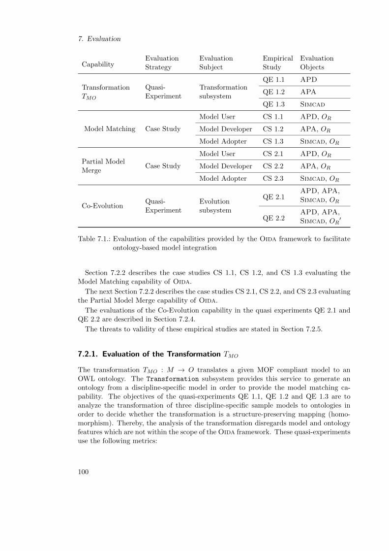
7. Evaluation
CapabilityEvaluation Evaluation Empirical EvaluationStrategy Subject Study Objects
TransformationTMO
Quasi-Experiment
Transformationsubsystem
QE 1.1 APD
QE 1.2 APA
QE 1.3 Simcad
Model Matching Case Study
Model User CS 1.1 APD, OR
Model Developer CS 1.2 APA, OR
Model Adopter CS 1.3 Simcad, OR
Partial ModelMerge
Case Study
Model User CS 2.1 APD, OR
Model Developer CS 2.2 APA, OR
Model Adopter CS 2.3 Simcad, OR
QE 2.1APD, APA,
Co-EvolutionQuasi-Experiment
Evolutionsubsystem
Simcad, OR
QE 2.2APD, APA,Simcad, OR
′
Table 7.1.: Evaluation of the capabilities provided by the Oida framework to facilitateontology-based model integration
Section 7.2.2 describes the case studies CS 1.1, CS 1.2, and CS 1.3 evaluating theModel Matching capability of Oida.
The next Section 7.2.2 describes the case studies CS 2.1, CS 2.2, and CS 2.3 evaluatingthe Partial Model Merge capability of Oida.
The evaluations of the Co-Evolution capability in the quasi experiments QE 2.1 andQE 2.2 are described in Section 7.2.4.
The threats to validity of these empirical studies are stated in Section 7.2.5.
7.2.1. Evaluation of the Transformation TMO
The transformation TMO : M → O translates a given MOF compliant model to anOWL ontology. The Transformation subsystem provides this service to generate anontology from a discipline-specific model in order to provide the model matching ca-pability. The objectives of the quasi-experiments QE 1.1, QE 1.2 and QE 1.3 are toanalyze the transformation of three discipline-specific sample models to ontologies inorder to decide whether the transformation is a structure-preserving mapping (homo-morphism). Thereby, the analysis of the transformation disregards model and ontologyfeatures which are not within the scope of the Oida framework. These quasi-experimentsuse the following metrics:
100
7.2. Empirical Studies
Integrity This measure is the basis for all further measurements. The integrity ofartifacts on both ends of the transformation TMO indicates whether the transformationmaintains intrinsic integrity which is defined by the validity of models and the consistencyof ontologies. The validity of the model as well as the consistency of the ontology canbe tested by algorithms which analyze the respective artifact based on the grammar ofthe modeling language and the ontology language. Model validation is mostly a syntaxvalidation whereas an ontology validation is done by testing the consistency of logicalstatements using automated reasoning.
Instance Entities The number of model objects at the instance level is compared to thenumber of individuals in the ontology. Equal numbers of individuals and model objectsindicate that the transformation is injective at the instance concept level.
Meta Entities The number of model classes ie compared to the number of ontologyclasses. Equal numbers of ontology classes and model classes indicate that the transfor-mation is injective at the meta concept level.
Meta Concept Links The number of model associations is compared to the number ofontology object properties. Equal numbers of object properties and associations indicatethat the transformation is injective at the meta concept level regarding the mapping ofconcept links.
Meta Attributes The number of model class attributes is compared to the number ofdatatype properties in the ontology. Instances of attributes, such as object attributesare not considered. Equal numbers of datatype properties and attributes indicate thatthe transformation is injective at the metaconcept level regarding the mapping of metaattributes.
Taxonomy Depth The maximal depth of the model inheritance forest1 is compared tothe maximal depth of the inheritance forest of the ontology. The taxonomy of the modeland the ontology can have a forest structure as the classes instantiated in the model donot have to be explicitly derived from a single class in the metamodel. Taxonomy depthis an important structural concept of both metamodels and ontologies. Equal taxonomydepths of model and ontology indicate that the transformation preserves the structureof inheritance relations.
Containment Depth The maximal depth of the model containment forest is comparedto the maximal depth of an equivalent forest in the ontology. EMF defines Containmentas a language construct. As OWL does not specify Containment, the partOf directly
object property was defined in the mereology.owl upper ontology and was consideredto be equivalent to Containment in EMF. The same upper ontology is used in the
1In this context a forest is a set of trees. A tree is a set of data organized in a tree structure.
101
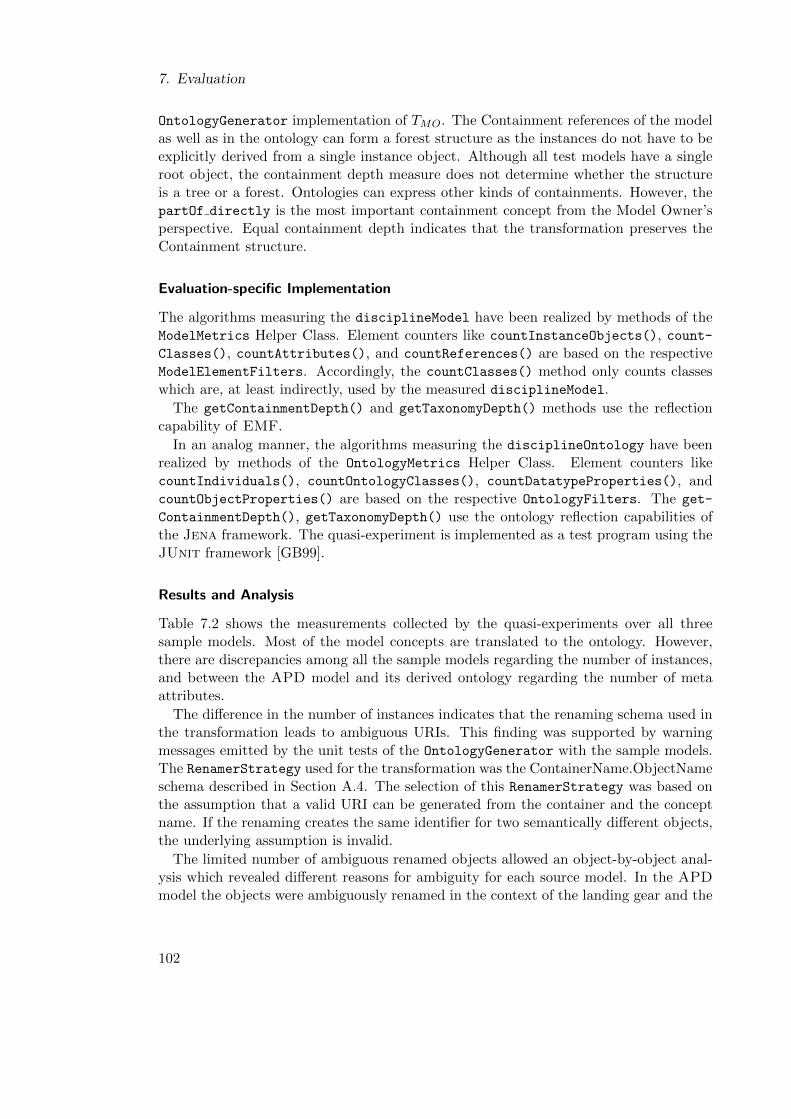
7. Evaluation
OntologyGenerator implementation of TMO. The Containment references of the modelas well as in the ontology can form a forest structure as the instances do not have to beexplicitly derived from a single instance object. Although all test models have a singleroot object, the containment depth measure does not determine whether the structureis a tree or a forest. Ontologies can express other kinds of containments. However, thepartOf directly is the most important containment concept from the Model Owner’sperspective. Equal containment depth indicates that the transformation preserves theContainment structure.
Evaluation-specific Implementation
The algorithms measuring the disciplineModel have been realized by methods of theModelMetrics Helper Class. Element counters like countInstanceObjects(), count-Classes(), countAttributes(), and countReferences() are based on the respectiveModelElementFilters. Accordingly, the countClasses() method only counts classeswhich are, at least indirectly, used by the measured disciplineModel.
The getContainmentDepth() and getTaxonomyDepth() methods use the reflectioncapability of EMF.
In an analog manner, the algorithms measuring the disciplineOntology have beenrealized by methods of the OntologyMetrics Helper Class. Element counters likecountIndividuals(), countOntologyClasses(), countDatatypeProperties(), andcountObjectProperties() are based on the respective OntologyFilters. The get-
ContainmentDepth(), getTaxonomyDepth() use the ontology reflection capabilities ofthe Jena framework. The quasi-experiment is implemented as a test program using theJUnit framework [GB99].
Results and Analysis
Table 7.2 shows the measurements collected by the quasi-experiments over all threesample models. Most of the model concepts are translated to the ontology. However,there are discrepancies among all the sample models regarding the number of instances,and between the APD model and its derived ontology regarding the number of metaattributes.
The difference in the number of instances indicates that the renaming schema used inthe transformation leads to ambiguous URIs. This finding was supported by warningmessages emitted by the unit tests of the OntologyGenerator with the sample models.The RenamerStrategy used for the transformation was the ContainerName.ObjectNameschema described in Section A.4. The selection of this RenamerStrategy was based onthe assumption that a valid URI can be generated from the container and the conceptname. If the renaming creates the same identifier for two semantically different objects,the underlying assumption is invalid.
The limited number of ambiguous renamed objects allowed an object-by-object anal-ysis which revealed different reasons for ambiguity for each source model. In the APDmodel the objects were ambiguously renamed in the context of the landing gear and the
102
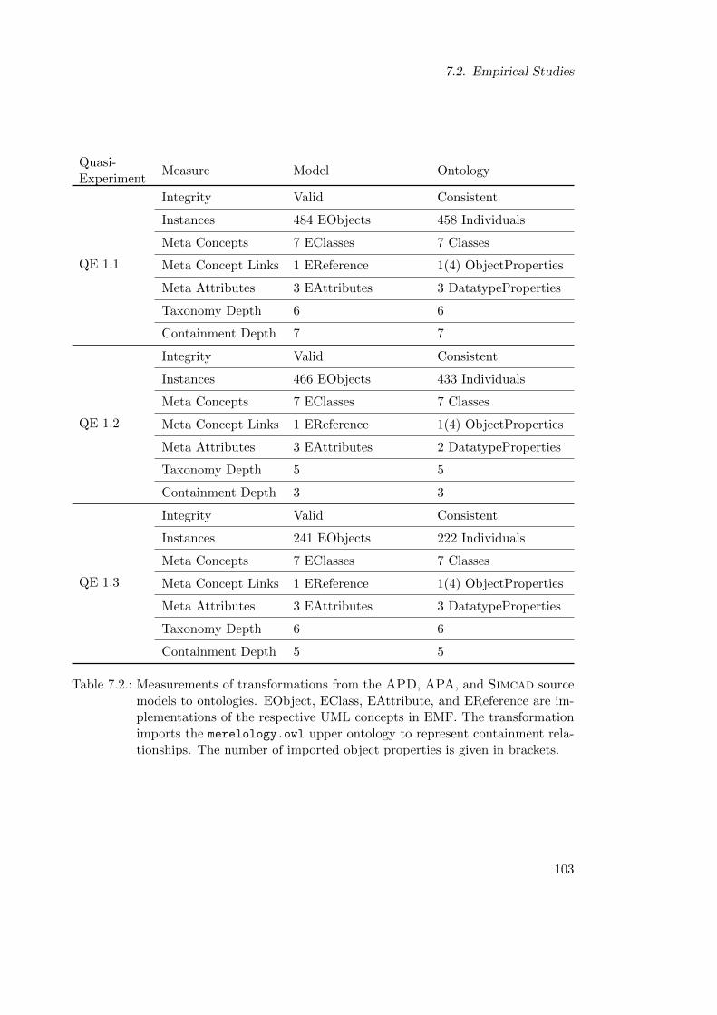
7.2. Empirical Studies
Quasi-Experiment
Measure Model Ontology
QE 1.1
Integrity Valid Consistent
Instances 484 EObjects 458 Individuals
Meta Concepts 7 EClasses 7 Classes
Meta Concept Links 1 EReference 1(4) ObjectProperties
Meta Attributes 3 EAttributes 3 DatatypeProperties
Taxonomy Depth 6 6
Containment Depth 7 7
QE 1.2
Integrity Valid Consistent
Instances 466 EObjects 433 Individuals
Meta Concepts 7 EClasses 7 Classes
Meta Concept Links 1 EReference 1(4) ObjectProperties
Meta Attributes 3 EAttributes 2 DatatypeProperties
Taxonomy Depth 5 5
Containment Depth 3 3
QE 1.3
Integrity Valid Consistent
Instances 241 EObjects 222 Individuals
Meta Concepts 7 EClasses 7 Classes
Meta Concept Links 1 EReference 1(4) ObjectProperties
Meta Attributes 3 EAttributes 3 DatatypeProperties
Taxonomy Depth 6 6
Containment Depth 5 5
Table 7.2.: Measurements of transformations from the APD, APA, and Simcad sourcemodels to ontologies. EObject, EClass, EAttribute, and EReference are im-plementations of the respective UML concepts in EMF. The transformationimports the merelology.owl upper ontology to represent containment rela-tionships. The number of imported object properties is given in brackets.
103
7. Evaluation
tank group of the main wing tank and the horizontal stabilizer. The reason is a reuseof the landing gear and tank group composite structure in several places in the model.The APD Model Owner considered a model modification that would solve the problemto be too complex.
An analysis of the ambiguously renamed objects of the APA model revealed a deepcopy of the containment tree under the geometry container node in the configuration
container node. The Model Owner of APA confirmed this observation. Tests witha ContainerContainerName.ContainerName.ObjectName RenamerStrategy showed nofalsely dropped objects for the given sample models. The renaming schema also droppedone of two attributes called value attribute. In fact, the given metamodel stipulatesa value attribute in both the IntegerValue and the FloatPointValue class. Thechosen RenamerStrategy using simply the StructuralFeatureName for attributes andassociations dropped one of these attributes. Tests with the given sample models usinga modification of the RenamerStrategy to ContainingClassName.attributeName showedno false dropping of attributes.
A closer analysis of the Simcad model revealed two reasons for ambiguous mappings,namely a bug in the OpenCDT tool connector, and a design principle of the Simcadmodel. Due to a bug in the OpenCDT tool connector the algorithm mistakenly createstwo mass container objects. The original Simcad data model file does not containthese doublets. Similar to APD, Simcad uses structural copies of the model tree torepresent different parts of the aircraft mission by the same parameters. Both casesof ambiguity in Simcad are not examined further in this evaluation as their originsare beyond the scope of the Oida framework. However, the ambiguities in the APAand the APD sample models were considered problematic and chosen for an exemplaryuse case of co-evolution due to modifications of the model integration framework andthe reference ontology modification. In order to create a base line, the case studiesevaluating the Model Matching and Partial Model Merge capabilities were conductedwithout modification to the renaming algorithm and the reference ontology.
7.2.2. Evaluation of the Model Matching Capability
The objective of evaluating the Model Matching capability of Oida is to analyze theperformance and the oral feedback of Model Owners during the matching process of hisaircraft model in order to determine the perceived efficiency of the Match Models usecase. The Model Matching capability was evaluated using the following measures:
Duration of Mapping This measure is the time span it takes the Model Owner tomap the elements of his discipline-specific model to the reference ontology. The timenecessary to get used to the user interface is not counted.
Mapped Model Objects During the case study the Model Owner maps objects fromhis discipline-specific model to the referenceOntology by equivalence statements. Thismeasure is given together with the total number of mappable model elements.
104
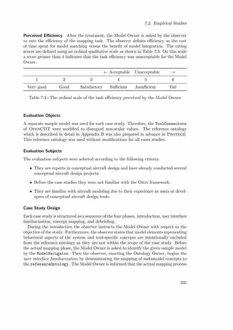
7.2. Empirical Studies
Perceived Efficiency After the treatment, the Model Owner is asked by the observerto rate the efficiency of the mapping task. The observer defines efficiency as the costof time spent for model matching versus the benefit of model integration. The ratingscores are defined using an ordinal qualitative scale as shown in Table 7.3. On this scalea score greater than 4 indicates that the task efficiency was unacceptable for the ModelOwner.
← Acceptable Unacceptable →
1 2 3 4 5 6
Very good Good Satisfactory Sufficient Insufficient Fail
Table 7.3.: The ordinal scale of the task efficiency perceived by the Model Owner
Evaluation Objects
A separate sample model was used for each case study. Therefore, the ToolConnectors
of OpenCDT were modified to disregard non-scalar values. The reference ontologywhich is described in detail in Appendix B was also prepared in advance in Protege.This reference ontology was used without modifications for all cases studies.
Evaluation Subjects
The evaluation subjects were selected according to the following criteria:
• They are experts in conceptual aircraft design and have already conducted severalconceptual aircraft design projects.
• Before the case studies they were not familiar with the Oida framework.
• They are familiar with aircraft modeling due to their experience as users or devel-opers of conceptual aircraft design tools.
Case Study Design
Each case study is structured as a sequence of the four phases, introduction, user interfacefamiliarization, concept mapping, and debriefing.
During the introduction the observer instructs the Model Owner with respect to theobjective of the study. Furthermore, the observer states that model elements representingbehavioral aspects of the system and tool-specific concepts are intentionally excludedfrom the reference ontology as they are not within the scope of the case study. Beforethe actual mapping phase, the Model Owner is asked to identify the given sample modelby the ModelNavigator. Then the observer, enacting the Ontology Owner, begins theuser interface familiarization by demonstrating the mapping of metamodel concepts tothe referenceOntology. The Model Owner is informed that the actual mapping process
105
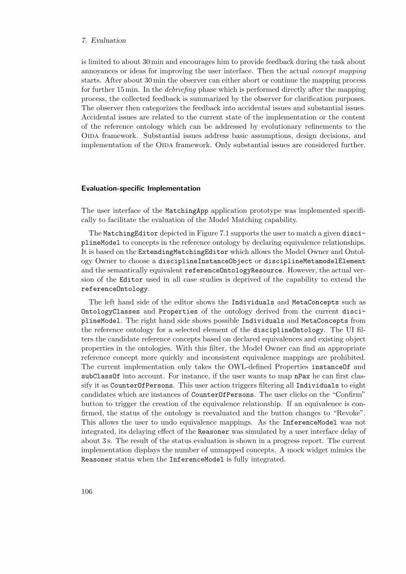
7. Evaluation
is limited to about 30 min and encourages him to provide feedback during the task aboutannoyances or ideas for improving the user interface. Then the actual concept mappingstarts. After about 30 min the observer can either abort or continue the mapping processfor further 15 min. In the debriefing phase which is performed directly after the mappingprocess, the collected feedback is summarized by the observer for clarification purposes.The observer then categorizes the feedback into accidental issues and substantial issues.Accidental issues are related to the current state of the implementation or the contentof the reference ontology which can be addressed by evolutionary refinements to theOida framework. Substantial issues address basic assumptions, design decisions, andimplementation of the Oida framework. Only substantial issues are considered further.
Evaluation-specific Implementation
The user interface of the MatchingApp application prototype was implemented specifi-cally to facilitate the evaluation of the Model Matching capability.
The MatchingEditor depicted in Figure 7.1 supports the user to match a given disci-
plineModel to concepts in the reference ontology by declaring equivalence relationships.It is based on the ExtendingMatchingEditor which allows the Model Owner and Ontol-ogy Owner to choose a disciplineInstanceObject or disciplineMetamodelElement
and the semantically equivalent referenceOntologyResource. However, the actual ver-sion of the Editor used in all case studies is deprived of the capability to extend thereferenceOntology.
The left hand side of the editor shows the Individuals and MetaConcepts such asOntologyClasses and Properties of the ontology derived from the current disci-
plineModel. The right hand side shows possible Individuals and MetaConcepts fromthe reference ontology for a selected element of the disciplineOntology. The UI fil-ters the candidate reference concepts based on declared equivalences and existing objectproperties in the ontologies. With this filter, the Model Owner can find an appropriatereference concept more quickly and inconsistent equivalence mappings are prohibited.The current implementation only takes the OWL-defined Properties instanceOf andsubClassOf into account. For instance, if the user wants to map nPax he can first clas-sify it as CounterOfPersons. This user action triggers filtering all Individuals to eightcandidates which are instances of CounterOfPersons. The user clicks on the “Confirm”button to trigger the creation of the equivalence relationship. If an equivalence is con-firmed, the status of the ontology is reevaluated and the button changes to “Revoke”.This allows the user to undo equivalence mappings. As the InferenceModel was notintegrated, its delaying effect of the Reasoner was simulated by a user interface delay ofabout 3 s. The result of the status evaluation is shown in a progress report. The currentimplementation displays the number of unmapped concepts. A mock widget mimics theReasoner status when the InferenceModel is fully integrated.
106
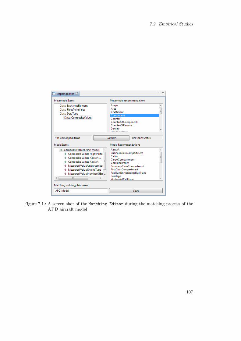
7.2. Empirical Studies
Figure 7.1.: A screen shot of the Matching Editor during the matching process of theAPD aircraft model
107
7. Evaluation
Case Study Execution
CS 1.1 Model User The evaluation subject in this case study is an aeronautics engineerwho is experienced in conceptual aircraft design in general and in using the APD tool inparticular. He was, however, not engaged in developing the APD tool, which qualifieshim as a Tool User.
The introduction and GUI familiarization took 10 min. During the user interfacefamiliarization the Tool User confirmed that the model was an APD model.
During the process he commented on substantial issues addressing the integration ofthe reasoner and the interactive modification of the reference ontology. The interactiondelay after each mapping which simulated the reasoner was perceived as very annoying.He proposed performing the check not after each mapping but on the user’s demand.
After 33 min the observer decided to stop the mapping process. At this point, theModel User had been able to map 45 of 458 possible model elements. During the de-briefing the Model User rated the task efficiency as “satisfactory”.
CS 1.2 Model Developer In the second case study, the evaluation subject was theModel Developer of APA who also frequently uses APA as a tool. Furthermore, thesame initial version of the referenceOntology was used as in CS 1.1.
The introduction took 9 min. Before the familiarization process, the Model Developerhad to delete parts of the model which were not within the scope of this case study, e.g.,simulation logs or non-scalar data structures. However, the Model Developer confirmedthat the integrity of the APD model regarding structural aspects of the aircraft were stillintact. In the next part of the case study, the observer demonstrated the user interfaceby mapping the metamodel. In this case only two attributes could be mapped. All otherentities had no equivalent concept. During the next 34 min, the Model Developer wasable to map 13 concepts. Thereby, the observer noted that about 80 % of the conceptsof the APA model did not exist in the reference ontology.
During the concept mapping phase, the Model Developer commented on issues ad-dressing the interaction design of the mapping task. The dynamic type casting of Mat-lab, where the APA sample model originates, can disturb the identity of model objectswithin the context of the MatchingApp application. In Matlab, the object identitydoes not change due to dynamic type casting. However, if a dynamically changed datatype is propagated to a Java runtime environment, the object identity changes com-pletely. Furthermore, assumptions about the semantics of data types can be misleading,for example, an item was casted as Integer but does not represent a counter. He alsosuggested that the software could take the order of magnitudes of attribute values in intoaccount to recommend matching individuals. Furthermore, he missed a feature whichwould allow the actors to add concepts to the referenceOntology. This feature wasdeliberately disabled during all case studies. He considered the presence of the OntologyOwner to be helpful for avoiding false equivalence statements or for finding appropriatereference concepts more quickly. The Model Owner did not perceive the delay by thesimulated Reasoner as an annoyance and rated the perceived task efficiency “satisfac-tory” to “sufficient”.
108
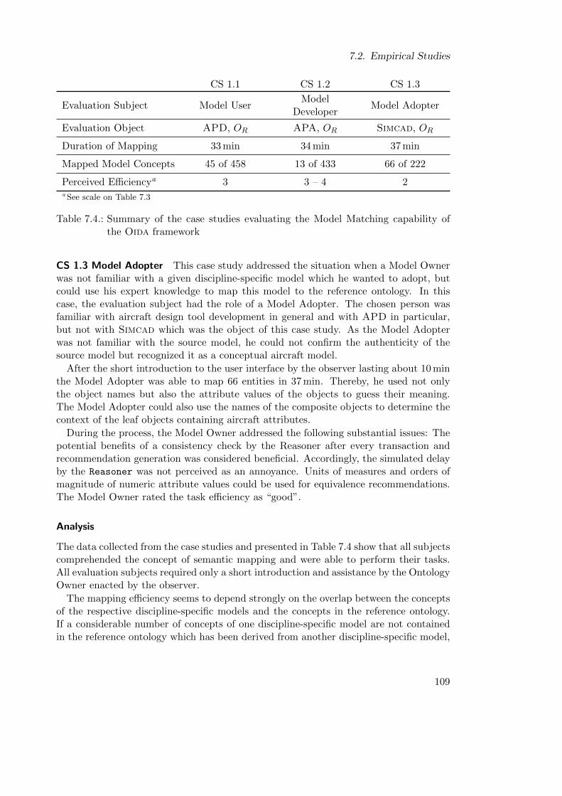
7.2. Empirical Studies
CS 1.1 CS 1.2 CS 1.3
Evaluation Subject Model UserModel
DeveloperModel Adopter
Evaluation Object APD, OR APA, OR Simcad, OR
Duration of Mapping 33 min 34 min 37 min
Mapped Model Concepts 45 of 458 13 of 433 66 of 222
Perceived Efficiencya 3 3 – 4 2a See scale on Table 7.3
Table 7.4.: Summary of the case studies evaluating the Model Matching capability ofthe Oida framework
CS 1.3 Model Adopter This case study addressed the situation when a Model Ownerwas not familiar with a given discipline-specific model which he wanted to adopt, butcould use his expert knowledge to map this model to the reference ontology. In thiscase, the evaluation subject had the role of a Model Adopter. The chosen person wasfamiliar with aircraft design tool development in general and with APD in particular,but not with Simcad which was the object of this case study. As the Model Adopterwas not familiar with the source model, he could not confirm the authenticity of thesource model but recognized it as a conceptual aircraft model.
After the short introduction to the user interface by the observer lasting about 10 minthe Model Adopter was able to map 66 entities in 37 min. Thereby, he used not onlythe object names but also the attribute values of the objects to guess their meaning.The Model Adopter could also use the names of the composite objects to determine thecontext of the leaf objects containing aircraft attributes.
During the process, the Model Owner addressed the following substantial issues: Thepotential benefits of a consistency check by the Reasoner after every transaction andrecommendation generation was considered beneficial. Accordingly, the simulated delayby the Reasoner was not perceived as an annoyance. Units of measures and orders ofmagnitude of numeric attribute values could be used for equivalence recommendations.The Model Owner rated the task efficiency as “good”.
Analysis
The data collected from the case studies and presented in Table 7.4 show that all subjectscomprehended the concept of semantic mapping and were able to perform their tasks.All evaluation subjects required only a short introduction and assistance by the OntologyOwner enacted by the observer.
The mapping efficiency seems to depend strongly on the overlap between the conceptsof the respective discipline-specific models and the concepts in the reference ontology.If a considerable number of concepts of one discipline-specific model are not containedin the reference ontology which has been derived from another discipline-specific model,
109
7. Evaluation
both models are either on different levels of detail or have a small semantic overlap.Therefore, it is important to provide a reference Ontology which covers most of theconcepts contained in the discipline-specific models.
Especially the third case study indicated that for the performance the Match Modelsuse case the Model Owner does not necessarily have to be familiar with the discipline-specific model in order to perform the mapping. All evaluation subjects suggested ex-ploiting the attribute values for equivalence recommendations. Especially the unit at-tribute was identified as an effective indicator for equivalence.
The results of the first and the third case study are very similar, though the scale of themodels and the relationship of the Model Owners to their respective discipline-specificmodel are different. Both the APD and Simcad models cover the overall aircraft systemwithout focusing on a specific system, whereas the APA model is focused on propulsionsystem architectures. As the Model Developer of APA could map considerably fewerconcepts to the reference ontology, the case studies could not show that the currentimplementation can bridge between models having a different focus.
7.2.3. Evaluation of the Partial Models Merge Capability
During the evaluation of the Partial Model Merge capability, the Model Owners arepresented with conflicts and import candidates. Both have been determined by matchingthe discipline-specific model which they are responsible for with the Chief EngineeringModel. Both models have been previously mapped to the reference ontology. The ModelOwner will not gain the full benefit of the Oida framework before this Merge ModelsPartially use case. Comparing conflicting values allows them to assess the effectivenessof the integration framework.
The objective of the case studies evaluating the Partial Model Merge capability isto analyze the feedback of the Model Owner regarding the perceived plausibility ofresults. In these case studies, the following measures were used which correspond to theterminology of the Oida design described in Chapter 6:
Semantic Matches The number of object pairs from the discipline-specific source andtarget model which could be matched by Oida.
Conflict Candidates The number of semantically matching object pairs which haveconflicting states detected by Oida.
Confirmed Conflicts The number of conflict candidates which have been confirmed bythe Model Owner.
Reported Conflicts The number of conflict candidates which have been reported bythe Model Owner due to suspected false matchings.
Import Candidates The number of objects from the discipline-specific source modelwhich Oida could not match with an object in the discipline-specific target model.
110
7.2. Empirical Studies
Confirmed Import Candidates The number of import candidates selected by the ModelOwner for import into his discipline-specific target model.
Reported Import Candidates The number of import candidates which have been re-ported by the Model Owner due to suspected false matchings.
Perceived Overall Efficiency The efficiency of the Match Models and Merge ModelsPartially use cases from the Model Owner’s perspective.
Result Plausibility The plausibility of the proposed conflict and import candidates withrespect to the method applied by the Oida framework and conveyed by the observer.
Evaluation Subjects
The evaluation subjects of these case studies were the same as in the previous casestudies. This implies that they were already informed about the overall procedure andcontext of the integration process. As with the previous case study, the observer enactedthe role of the Ontology Owner.
Evaluation Objects
In these case studies, the same APD and APA sample models were used as in theprevious case studies. The Simcad model was declared both the Chief EngineeringModel, which overrides the APD and APA model in the case of conflict, and the sourcemodel of Migrate Model Parts. Furthermore, the ontologies containing the equivalencestatements created in the first phase of the case studies were used.
Case Study Design
The case studies addressing the Partial Model Merge capability evaluated the plausibilityof the matching results perceived by the evaluation subjects. Furthermore, at the endof the Merge Models Partially use case, the conflict resolutions are propagated to thediscipline-specific target model and the ontologies are checked for consistency with thischanged target model. The case studies consist of the following phases: introduction,conflict resolution, partial model import, and debriefing.
In the introduction phase of the case study, the Ontology Owner explains the task tothe Model Owner. The Model Owner is instructed that he will not be able to overrideincoming changes but has to assess whether the incoming values make sense. It is furtheragreed that Model Owner and Ontology Owner can talk freely about the user interfaceand presented conflict and import candidates. The Model Owner is also informed thatthe time until completion of the task is recorded.
During conflict resolution, the Model Owner is presented with a list of conflictingobjects. He sees both object names from the target model and the reference ontologybut is not provided with the object name from the source model. The only way he
111
7. Evaluation
can assess the plausibility is the order of magnitude of numerical attribute values and,if available, the unit attribute. The Model Owner confirms the plausibility of eachconflict or explicitly declines it. The Model Owner completes the conflict resolution,which triggers the transformation of the result to the discipline-specific target model.Subsequently, the Model Owner has to confirm that the conflict resolution has preservedthe nomenclature and structure of the discipline-specific target model.
At the beginning of partial model import , the user interface provides a list of modelobjects of the incoming model which could not be matched with the target model. TheModel Owner can decide which objects he wants to import and chooses an object nameand a container appropriate to his own naming convention and model decompositionstrategy.
In the debriefing phase, the Ontology Owner wraps up the feedback which was col-lected during the session. The Model Owner is further asked whether he considers thematching result plausible and whether the preceding phases of the case study were per-ceived to be useful in the retrospective on the scale shown in Table 7.3
Case Study Execution
Based on the results of the evaluation described in Section 7.2.2 the following casestudies are executed when Model Owners want to check whether their respective modelhas conflicts with the ChiefEngineeringModel, and to select objects for import fromthat model.
CS 2.1 Model User
This case study was performed with the same evaluation objects and subjects as inCS 1.1. First, the Model User confirmed that the model represented an APD model.
It required about 5 min of introduction by the observer before the Model Owner couldbegin with the conflict resolution using the ImportCandidateReviewForm. The ModelUser confirmed 14 conflicts and reported 4 of 18 conflicts, because the incoming valuesappeared to be undefined. Then the Ontology Owner proceeded to the MigrateDia-
log. After a short introduction by the observer, the Model User confirmed no importcandidate and reported 28 of 47 import candidates. The Model User explained thatthe Simcad model appeared to provide more details on aircraft cabin design than theAPD model. In its own work flow, the cabin interior was designed in a separate CADapplication. He also stated that importing data on demand was effective to manage thecomplexity. He was sure that all incoming values he reported were already in the APDmodel but were not mapped to the reference ontology in CS 1.1. Another Match Modelssession would be required to completely map the APD model to the reference ontology.The conflict resolution and migration parts were concluded after 17 min. In the debrief-ing, the Model User gave the matching process an efficiency rating of “good”, giventhat the Oida framework provides the Co-evolution capability. He also mentioned, thatthe mapping procedure could be an error-prone task. Therefore, the number of map-pings should be reduced as much as possible. Generally, he considered the results of the
112
7.2. Empirical Studies
matching process plausible. The reported conflicts and Simcad data elements seemedto him more the result of mapping error by another Model Owner than an error by thesystem.
CS 2.2 Model Developer The introduction phase took 5 min. At the end of the in-troduction, the Model Developer recognized the APA sample model as his model. Dur-ing the conflict resolution phase the Model Developer criticized that the user interfacepresents the model elements without their context which makes it difficult to compre-hend the meaning of the elements. For instance, the thrust of an engine has almost nomeaning without setting it in the context of the velocity, pressure and temperature ofthe currently surrounding atmosphere. The Model Developer commented on the char-acter of the values coming from the Chief Engineering Model. For instance, he assessedthe empennage as an aggressive design. The Model Developer confirmed all presentedconflicts. The conflict resolution phase ended after 8 min. During the model migrationphase he noted that the units of the incoming system attributes seemed to match hisimplicit convention for units of attributes in the APD model. However, further im-plementations should provide automated unit conversion or a generic conversion factor.He was sure that most of the import candidates were already in his model but werenot mapped during CS 1.1. Accordingly, he reported most of the import candidatesas errors. However, he imported two model elements into his structure using the userinterface to create the appropriate container model element in his model. The migrationphase ended after 10 min. In retrospect, he perceived the efficiency of the process asbetter than in the first case study C 1.2 and rated it “good” to “satisfactory”. He alsoconsidered the result plausible.
CS 2.3 Model Adopter In this case study the model owner enacted the role of auser who wants to import a model from Simcad to APD. During the introduction heidentified the APD sample model using the ModelNavigator. The introduction tookabout 5 min. The Model Adopter had not mapped the APD model himself. Therefore,he had to trust another Model Adopter to have performed the mapping correctly. Theuser interface did not help him to achieve an overview of the model structure as theconflicts are provided as a list. He only reported one value which, in his opinion, wasobviously mapped wrongly by the APD Model Owner. The conflict resolution phaseended after 15 min. The Model Adopter started the migrate dialog. He imported 7of 47 import candidates which he considered relevant for the scope of APD and usedthe user interface to declare a suitable container for the new elements and to assignsuitable names. Thereby, he commented that it would improve the efficiency if thenomenclature from the reference ontology could be taken over automatically. In somecases, the Model Owner chose to confirm model elements whose attribute values werenot set. He expected the values to be set in future iterations, and wanted to “subscribe”to these model elements. He reported 8 of 47 proposed import candidates because he wassure that they were already in the discipline-specific target model but not mapped by itsModel Owner during CS 1.1. In his opinion, the user should be able to map a proposed
113
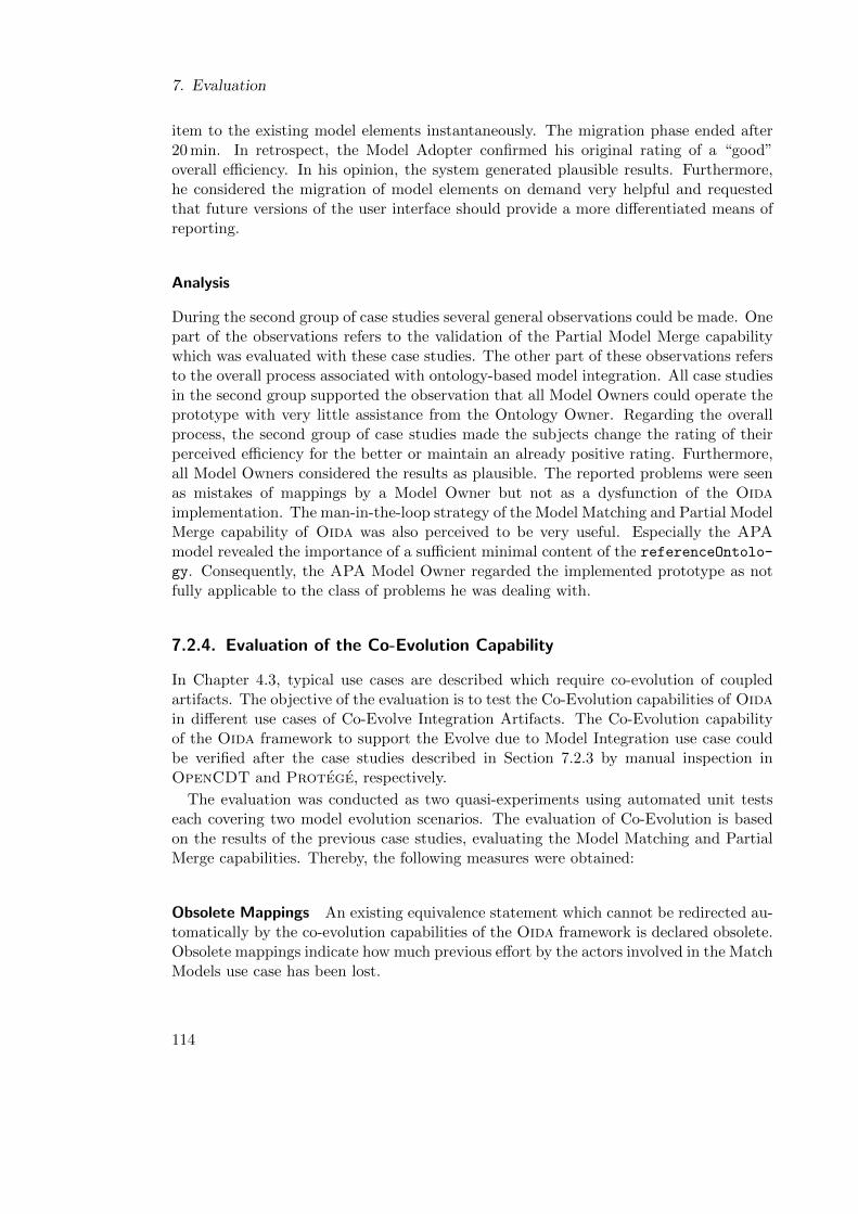
7. Evaluation
item to the existing model elements instantaneously. The migration phase ended after20 min. In retrospect, the Model Adopter confirmed his original rating of a “good”overall efficiency. In his opinion, the system generated plausible results. Furthermore,he considered the migration of model elements on demand very helpful and requestedthat future versions of the user interface should provide a more differentiated means ofreporting.
Analysis
During the second group of case studies several general observations could be made. Onepart of the observations refers to the validation of the Partial Model Merge capabilitywhich was evaluated with these case studies. The other part of these observations refersto the overall process associated with ontology-based model integration. All case studiesin the second group supported the observation that all Model Owners could operate theprototype with very little assistance from the Ontology Owner. Regarding the overallprocess, the second group of case studies made the subjects change the rating of theirperceived efficiency for the better or maintain an already positive rating. Furthermore,all Model Owners considered the results as plausible. The reported problems were seenas mistakes of mappings by a Model Owner but not as a dysfunction of the Oidaimplementation. The man-in-the-loop strategy of the Model Matching and Partial ModelMerge capability of Oida was also perceived to be very useful. Especially the APAmodel revealed the importance of a sufficient minimal content of the referenceOntolo-
gy. Consequently, the APA Model Owner regarded the implemented prototype as notfully applicable to the class of problems he was dealing with.
7.2.4. Evaluation of the Co-Evolution Capability
In Chapter 4.3, typical use cases are described which require co-evolution of coupledartifacts. The objective of the evaluation is to test the Co-Evolution capabilities of Oidain different use cases of Co-Evolve Integration Artifacts. The Co-Evolution capabilityof the Oida framework to support the Evolve due to Model Integration use case couldbe verified after the case studies described in Section 7.2.3 by manual inspection inOpenCDT and Protege, respectively.
The evaluation was conducted as two quasi-experiments using automated unit testseach covering two model evolution scenarios. The evaluation of Co-Evolution is basedon the results of the previous case studies, evaluating the Model Matching and PartialMerge capabilities. Thereby, the following measures were obtained:
Obsolete Mappings An existing equivalence statement which cannot be redirected au-tomatically by the co-evolution capabilities of the Oida framework is declared obsolete.Obsolete mappings indicate how much previous effort by the actors involved in the MatchModels use case has been lost.
114
7.2. Empirical Studies
CS 2.1 CS 2.2 CS 2.3
Evaluation Subject Model UserModel
DeveloperModel Adopter
Evaluation Object APD APA APD
Chief Engineering Model Simcad Simcad Simcad
Semantic Matches 18 6 18
Conflict Candidates 18 6 18
Confirmed Conflicts 14 6 17
Reported Conflicts 4 0 1
Import Candidates 47 59 47
Confirmed Import Candidates 0 2 7
Reported Import Candidates 28 0 8
Perceived Overall Efficiencya 2 2 – 3 2
Result Plausibility yes yes yesa See scale in Table 7.3
Table 7.5.: Measurements from the case studies evaluating the Partial Model Merge ca-pability of the Oida framework
115
7. Evaluation
Mappings Required by the Model Owner The number of manual actions requiredby the Model Owner to make the previously mapped ontology consistent with the newversion of the model. It is only concerned with revising obsolete and creating new equiv-alence statements from discipline-specific instance concepts to the reference ontology.This implies that the Model Owner is usually not concerned with mapping conceptsfrom the metamodel. This measure can be correlated with the Obsolete Mappings mea-sure. Obsolete mappings have to be discarded or remapped manually by the OntologyOwner or Model Owner in order to maintain the same level of semantic coupling thatexisted before the evolution. More Required Mappings by Model Owner than ObsoleteMappings indicate that the modification created new discipline-specific instance con-cepts.
Creation of Reference Concepts A number of reference concepts need to be created inorder to make the reference ontology consistent with the evolved models. In the currentconcept of Match Models, this task is performed in a collaboration between Model Ownerand Ontology Owner. Therefore, this measure indicates the effort required from bothactors.
Mappings Required by the Ontology Owner The number of mappings which makethe evolved ontologies and models consistent at the metaconcept level. According to theinteraction design of the Oida framework, the Ontology Owner is responsible for thistask. Therefore, this measure indicates the effort required from the Ontology Owner.
Evaluation-specific Implementation
The Partial Model Merge capability of the Oida framework is realized in MergeCon-
trol of the Merge plug-in. The supporting capabilities for the other Co-Evolve Inte-gration Artifacts use cases are implemented in the Evolution plug-in. The two classesRenameReference and ImportPreviousMappings implement two kinds of Knowledge-
Sources.
The RenameReference addresses the Evolve due to Reference Ontology Maintenanceand implements the EvolutionAlgorithm as the implementation is based on the assump-tion that there is exact knowledge of the modification, the artifacts, and the couplingsbetween them is known. In particular, this class realizes a support for a Rename refac-toring of the referenceOntology. If an OntologyResouce in the referenceOntology
is renamed, not only the Properties pointing to that entity within the referenceOnto-logy but also equivalence statements from disciplineOntologies have to be updated.As the Blackboard pattern was not implemented, RenameReference was realized asa preprocessor for the Match Models use case which could be tested separately fromthe Matching plug-in. RenameReference requires an old referenceOntology and alist of old disciplineOntologies which contain equivalence statements to the old re-
ferenceOntology. Then it performs the RenameRefactoring to Properties, Classesand Individuals. Equivalence statements which become obsolete are discarded and
116
7.2. Empirical Studies
counted for measurement. Successfully adjusted old equivalence statements are auto-matically created in the regenerated new versions of disciplineOntologies.
The ImportPreviousMappings class addresses all use cases of model co-evolutionexcept the first, based on the assumption that the exact modification to the coupledartifacts is unknown. Accordingly, it implements the EvolutionHeuristic interface.Equivalence statements are the most expensively created objects of the ontology-basedmodel integration approach with respect to the required work time of the Model Owners.Therefore, the implementation of ImportPreviousMappings focuses on the task to im-port as many previously made ImportPreviousMappings as possible, regardless of whichkind of modification has taken place. As the Blackboard pattern was not implemented,ImportPreviousMappings was implemented as a preprocessor to MatchingControl andwas integrated with the user interface demonstrator ExtendingMatchingEditor. Givena newly generated disciplineOntology and a new referenceOntology and the respec-tive previous versions, the implemented heuristic first extracts equivalence statementsfrom the old versions. Only if both ends of such equivalence statements can be un-ambiguously correlated to a new concept, they are recreated in the newly generateddisciplineOntologies, otherwise are they discarded and counted as obsolete equiva-lence statements.
Quasi-Experiments
The quasi-experiments for the evaluation of co-evolution are realized as unit tests basedon the disciplineOntologies which have been generated from the sample models andmapped by the original Model Owners in CS 1.1, CS 1.2, and CS 1.3. The measurementsof Obsolete Mappings are provided by ImportPreviousMappings and RenameReference.The other measurements result from the use of matching and reference creation methodsin the respective unit test implementation.
QE 2.1: Co-Evolution due to modeling This automated test stages the situationafter an initial integration process when the Model Owner modifies his discipline-specificmodel by changing the name of an object and by creating a new object. Thereby, theperformance of the Oida framework regarding the Evolve due to Aircraft Modeling usecase can be measured. The test executes the Match Models use case and automaticallyperforms the required actions for Co-Evolution and validates the consistency. Thereby,the measurements relevant for the Co-Evolution capability defined above are acquired.
In particular, the automated test changes the name of the object representing thewing span to full wing span in the appropriate nomenclature of the respective modelwhich represents a Rename refactoring. Then a new model element is created whichrepresents the maximum cabin pressure. The test run is performed with each samplemodel separately.
QE 2.2: Algorithm and Reference Ontology Modification The objective of this quasi-experiment is to determine how much effort is required for the co-evolution of all artifacts
117
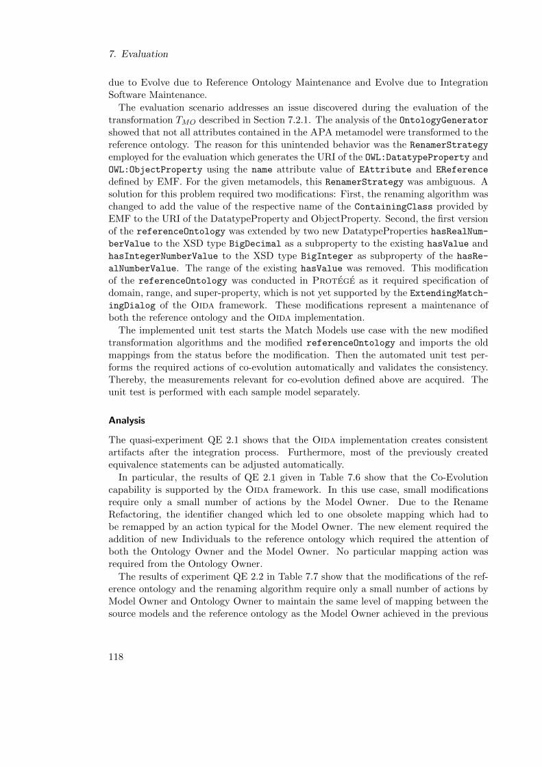
7. Evaluation
due to Evolve due to Reference Ontology Maintenance and Evolve due to IntegrationSoftware Maintenance.
The evaluation scenario addresses an issue discovered during the evaluation of thetransformation TMO described in Section 7.2.1. The analysis of the OntologyGeneratorshowed that not all attributes contained in the APA metamodel were transformed to thereference ontology. The reason for this unintended behavior was the RenamerStrategy
employed for the evaluation which generates the URI of the OWL:DatatypeProperty andOWL:ObjectProperty using the name attribute value of EAttribute and EReference
defined by EMF. For the given metamodels, this RenamerStrategy was ambiguous. Asolution for this problem required two modifications: First, the renaming algorithm waschanged to add the value of the respective name of the ContainingClass provided byEMF to the URI of the DatatypeProperty and ObjectProperty. Second, the first versionof the referenceOntology was extended by two new DatatypeProperties hasRealNum-berValue to the XSD type BigDecimal as a subproperty to the existing hasValue andhasIntegerNumberValue to the XSD type BigInteger as subproperty of the hasRe-
alNumberValue. The range of the existing hasValue was removed. This modificationof the referenceOntology was conducted in Protege as it required specification ofdomain, range, and super-property, which is not yet supported by the ExtendingMatch-ingDialog of the Oida framework. These modifications represent a maintenance ofboth the reference ontology and the Oida implementation.
The implemented unit test starts the Match Models use case with the new modifiedtransformation algorithms and the modified referenceOntology and imports the oldmappings from the status before the modification. Then the automated unit test per-forms the required actions of co-evolution automatically and validates the consistency.Thereby, the measurements relevant for co-evolution defined above are acquired. Theunit test is performed with each sample model separately.
Analysis
The quasi-experiment QE 2.1 shows that the Oida implementation creates consistentartifacts after the integration process. Furthermore, most of the previously createdequivalence statements can be adjusted automatically.
In particular, the results of QE 2.1 given in Table 7.6 show that the Co-Evolutioncapability is supported by the Oida framework. In this use case, small modificationsrequire only a small number of actions by the Model Owner. Due to the RenameRefactoring, the identifier changed which led to one obsolete mapping which had tobe remapped by an action typical for the Model Owner. The new element required theaddition of new Individuals to the reference ontology which required the attention ofboth the Ontology Owner and the Model Owner. No particular mapping action wasrequired from the Ontology Owner.
The results of experiment QE 2.2 in Table 7.7 show that the modifications of the ref-erence ontology and the renaming algorithm require only a small number of actions byModel Owner and Ontology Owner to maintain the same level of mapping between thesource models and the reference ontology as the Model Owner achieved in the previous
118
7.2. Empirical Studies
APD APA Simcad
Ch
an
ges New model elements 1 1 1
Modified model elements 1 1 1
New reference concepts 0 0 0
Act
ion
s
Obsolete mappings 1 1 1
Mappings by Model Owner 2 2 2
Creation of reference concepts 1 1 1
Mappings by Ontology Owner 0 0 0
Table 7.6.: The modifications versus the required actions by the Ontology Owner andModel Owner observed in the automated test QE 2.1
APD APA Simcad
Ch
ange
s New individuals 26 33 18
New classes 0 0 0
Creation of reference concepts 2 2 2
Act
ion
s
Obsolete mappings 0 4 0
Mappings by Model Owner 0 6 0
Creation of reference concepts 0 0 0
Mappings by Ontology Owner 0 2 1
Table 7.7.: The modifications versus the required actions by the Ontology Owner andModel Owner observed in the automated test QE 2.2
119
7. Evaluation
Match Models use case. Almost all equivalence statements could be imported automati-cally. Only the mapping of the hasValue property was declared obsolete as the source ofthe object property did not exist anymore in the newly derived ontology. The OntologyOwner only had to map the new object properties IntegerValue:value and Double-
Value:value to hasIntegerNumberValue and hasRealNumberValue, respectively. Nonew concepts had to be added to the reference ontology. Subsequent tests showed thatthe Merging plug-in can handle the situation in which Counters like nPax which hadbeen mapped to NumberOfPassengers had a value attribute as Double data type inthe source model but an Integer attribute in the reference representation of the model.
7.2.5. Threats to Validity
Due to the following threats, the validation obtained from this evaluation provides onlyanecdotal evidence. The small sample size of the evaluation is too small to generalizethe conclusions to other scales of model complexity and other combinations of engineer-ing disciplines. Furthermore, the three professionals were voluntary, that is, we usedconvenience sampling. Due to the very limited availability of test models and qualifiedModel Owners, the subjects were also not randomly selected. For the APA model, thereis only one developer and user. Therefore, the conclusions might also be affected bybias. There is a possibility that experimental conditions, namely the different overlap-pings between sample models and the reference ontology, could make a difference onhow participants perceive the tool they had to use. The participants of the experimentswere aware that their work was being measured. Therefore, there is a chance that theparticipants presented a modified or improved behavior. Based on the Hawthorneeffect [Ada84], qualities measured in the study could be more than those of real world.
7.3. Results
Regarding the objectives of the evaluation stated before, the following results were at-tained:
Regarding model and metamodel features which are considered most important for theModel Owners of the sample models, the transformation is structure-preserving (homo-morphism). The evaluation also revealed that for some metamodel and model elements,the transformation was ineffective in generating unique ontology resource identifiers.This issue was addressed by an instance of an Evolve due to Integration Software Main-tenance use case which resolved the issue for the particular sample models. However, theissue illustrates the importance of evaluating the effectiveness of Oida transformationsfor a concrete application.
The preparation of the case studies CS 1.1, CS 1.2, and CS 1.3 evaluating the in-teractive Model Matching capability revealed the ineffectiveness of the NameEquiva-
lenceFinder and the SemanticValidator for the given sample models. Therefore, thecase studies were performed on a prototype which only provides the manual matchingcapability without using a Blackboard pattern infrastructure. Due to time restric-tions of the case studies the sample models could not be matched completely against the
120
7.3. Results
reference. However, in the case studies CS 2.1, CS 2.2, and CS 2.3 evaluating PartialModel Merge capability, the Oida prototype detected 18 conflicts between APD andSimcad and 6 conflicts between APA and Simcad and successfully imported all selectedunmatched model objects. Due to the incomplete matching to the reference ontology,not all conflicts could be identified. Accordingly, all case studies showed that the in-teraction design of the Oida framework is effective in facilitating ontology-based modelintegration. In particular, the feedback from the Model Owners during the case stud-ies indicates that the work flow of the Oida applications was understood quickly. TheModel Owners considered the work flow sufficiently efficient and the produced resultssuch as conflict and import candidates to be plausible.
The case studies also revealed that ReferenceOntology should contain most of theconcepts used in the DisciplineModels before the Match Models use case is started.Furthermore, the MatchingApp application should provide the capability to extend theReferenceOntology. The latter was deliberately disabled during the case studies.
The quasi-experiment evaluating the Co-Evolution capability showed the effectivenessof both heuristic and algorithmic approaches in the Oida framework for exemplaryinstances of the Co-Evolve Integration Artifacts use case. In particular, in all quasi-experiments of QE 2.1 and QE 2.2, the Oida prototype always required an equal or lowernumber of actions compared to the number of changes between artifact versions. Despitethis successful proof-of-concept, the current implementation did not allow the evaluationof Co-Evolution KnowlegeSources within the context of the envisioned Blackboardpattern.
121

8. Conclusion and Outlook
Ontology-based model integration addresses the problem of inconsistencies between themany aircraft models that are created in a conceptual aircraft design process, and theinefficient migration of model elements between discipline-specific models. In this dis-sertation, these problems have been analyzed using three typical aircraft concept modelsfrom different provenience, scope and level of detail. Based on this analysis, the Oidaframework has been designed to provide the ontology-based model integration capabilityengaging the Model Owners in an interactive process. This process and a prototype ofthe Oida framework have been evaluated by quasi-experiments and case studies usingreal conceptual aircraft models as sample models and the respective Model Owners asparticipants. In this evaluation, the Oida prototype demonstrated conflict resolutionand migration of selected model elements between the sample models.
The analysis and the development of Oida was focused on the integration of structuralaspects of the aircraft concept models. Further research is required to investigate whetherontology-based model integration can be applied to more aspects of an aircraft modelor even to other domains of engineering.
This dissertation shows how ex post semi-automated application of formal seman-tics to existing conceptual aircraft models and their evaluation enables model matchingacross different naming conventions and decomposition strategies, the identification ofconflicts between equivalent model elements, and the selective migration of model parts.Presumably, an earlier integration of formal semantics in models and metamodels and adeeper integration of semantic technologies into the design work flow will not only im-prove the efficiency of communication between heterogeneous information systems butalso facilitate better human-machine interfaces in computer-aided design.
8.1. Contributions
The Oida framework described in this dissertation was developed and evaluated ad-dressing the research questions stated in Chapter 1. The following contributions weremade:
Analysis of Conceptual Aircraft Models Three sample models were analyzed in orderto observe and classify differences between conceptual aircraft models which cause alack of efficiency and effectiveness in existing model merging techniques. The samplemodels were created in tools currently used by industry and academia for conceptualaircraft design. The sample models represented the same aircraft type but were createdwith different scope and focus. The parts of the sample models representing structural
123
8. Conclusion and Outlook
aspects of the aircraft were transformed to the same metamodel using existing Tool-
Connectors provided by OpenCDT. Thereby, the transformation allowed manual andautomated inspections on a common syntactic basis. Despite the common metamodel,the sample models revealed considerably different naming conventions stemming fromdifferent coding styles of the developers and users of the sample models. Furthermore,the sample models exhibited different decomposition strategies. This indicates a gap be-tween the abstraction level of the metamodel and the application domain which prohibitsthe automated identification of objects representing the same physical object by theirproperties. Accordingly, a more concrete modeling standard would facilitate finding asolution. However, especially a unification of the design-process-oriented decompositionlimits the designers in organizing their models according to their specific methodology.Furthermore, conceptual designers explore new component layouts and system configu-rations which are not standardized for their domain.
These insights have not only been the design driver for the Oida framework but canalso serve as a basis for alternative solutions. However, this analysis disregards parts ofthe sample models which represent behavioral aspects of the aircraft system. Future workin the context of model integration in conceptual design should examine these aspectswhich are especially relevant for the design and assessment of operational capabilities ofan aircraft.
Ontology-based Model Integration Conventional model merge techniques have a num-ber of shortcomings. To compensate for these the Oida framework was developed alsowith view to transparency and user control.
In order to compensate for the shortcomings of conventional model merge techniques,the Oida framework was developed. The Oida framework is designed towards trans-parency and user control. Therefore, it engages the Model Owner who is the personsresponsible for a given conceptual model to declare the meaning of model and metamodelelements by equivalence statements.
Instead of using a central all-comprising model as a reference, the solution employsan ontology which provides reference entities. Thereby, the ontology language allowsformal definition of semantics of the reference concepts formally by logical statements.The interactive integration process has two phases: In the first phase, each Model Ownercreates equivalence statements from his model and metamodel elements to the referenceconcepts. In the second phase, these equivalence statements are evaluated automaticallyin order to match model elements and identify conflicts between them. The ModelOwner then decides on conflict resolutions and selects the model elements he wants toimport from other models. In contrast to classic model merge techniques which result ina consistent union of the integrated models, the Oida framework leaves model specificnaming convention and decomposition strategies intact and allows the Model Owners tomanage the degree of semantic overlap and thus to keep the complexity of their modelsdown to a practical minimum.
The Oida framework has been designed to facilitate this process. In particular, thedesign realizes the interactive matching of discipline-specific models with a reference
124
8.1. Contributions
ontology by employing a Blackboard pattern, which allows a combination of bothautomated and manual match finder, review, and validation capabilities. The prototyp-ical implementation of the Oida framework is based on common modeling and ontologyframeworks and was evaluated by automated quasi-experiments and interactive casestudies with the same sample models as are used in the analysis of conceptual aircraftmodels, engaging their respective Model Owners. Preliminary unit tests revealed thatsome of the envisioned automated KnowledgeSources could not contribute to the match-ing process for the given sample models. In particular, the ontology consistency check bythe reasoner took considerably more time than should have been required. Therefore, theprototype employs only manual KnowledgeSources without implementing the Back-board pattern. Nevertheless, the prototype could identify conflicts between equivalentobjects and was able to move selected model elements between given sample models.After participating in the case studies, all Model Owners rated the prototypical ModelMatching and Partial Model Merge process better than sufficiently efficient and consid-ered the results plausible.
The analysis of the evaluation suggests three steps for improving the Oida framework.First, automated KnowledgeSources need to be integrated into the Oida implementa-tion. For instance, the InferenceModel can contribute by automated classification ofOntologyResources and by checking the consistency of ontologies. Thereby, the in-tegration of computationally intensive KnowledgeSources to a responsive interactiveBlackboard will be included in future research. Secondly, simple equivalence map-pings limit the integration capability to one-to-one matchings of concepts. One-to-manymappings would enable the integration of more heterogeneous models and enable thedesigners to better adapt their tools to their respective methodology. Thirdly, the ref-erence ontology must cover at least all domain concepts of the models involved in anintegration process. Additionally, the scope of the reference ontology should be extendedto complex data types such as vectors and to behavioral aspects of aircraft systems.
Evolution of the Integration System The case studies showed that at least the initialeffort required from the Model Owners in performing the ontology-based model inte-gration process is considerable. However, the extent and the complexity of differencesbetween concurrently evolving models depends on how frequently the integration processis performed. Therefore, how the efforts of the users for subsequent integration processesof concurrently evolving models could be reduced was investigated. The problem wastackled by defining four distinct use cases in which relevant artifacts evolve. Each casewas analyzed as to whether the Oida framework can control this evolution by exploit-ing available knowledge or applying heuristics in order to limit the effort required fromModel Owners and the Ontology Owner. The Oida design was extended by algorith-mic and heuristic KnowledgeSources which were implemented in the Oida prototype.Automated quasi-experiments demonstrated that the Oida prototype is capable of con-siderably diminishing the effort required from Model Owners and the Ontology Ownerin all four cases of evolution.
125
8. Conclusion and Outlook
8.2. Integrating other Dimensions of Conceptual Models
The Oida framework demonstrates a solution for collaboration in conceptual aircraft de-sign made possible by the ex post introduction of formal semantics into existing modelsby equivalence statements between model and metamodel elements to shared referenceontology concepts. In principle, designers could assign formal semantics to every modelelement at the beginning of its information life cycle and modify it if necessary. Thereby,the Match Models and Co-Evolve Integration Artifacts use cases would be reduced tosmall tasks which could be seamlessly integrated into the modeling work flow. Presum-ably, the guaranteed availability of object semantics facilitates the extension of ontology-based model integration between other design dimensions such as levels of detail, designvariants, or design phases.
The current concept described in this dissertation assumes that a model does notonly contain detailed system attributes but also aggregated system attributes which arecoupled with the detailed attributes. For instance, the sample models specify the massof subcomponents such as wing and fuselage, but also explicitly define the aggregatedmass of the overall aircraft. This redundancy can be used to check the consistency ofalgorithms in a conceptual aircraft model. Furthermore, it allows for correlating differentmodels with different levels of detail, if the models is composed the same way. Thereby,it will be a challenge to implement such a reference ontology in a way that it providesa standard composition without limiting the concept designer’s flexibility regarding thesystem topology.
Especially during conceptual aircraft design, not only off-design operation scenariosbut also design alternatives are explored and assessed. The latter represent productswhich significantly diverge by system attributes and also system topology. An earlymapping of design alternatives to a common reference ontology could help to identifycommon model elements and keep them consistent.
Not only the integration of concurrent design models but also the explicit couplingand consistency between models of different design phases is desirable for a sustainableproduct design process, especially, after the conceptual design phase model elementsbasically transit to another level of abstraction. For instance, in an early stage of thedevelopment a NewPlaneStarboardEngine is perceived as an instance object whereas,in later design phases, it is perceived more as a class. For such a class, an appropriateinstance object would be NewPlane001StarboardEngine. The ultimate challenge for asystem integrating different levels of abstraction is the transition between virtual modelsand physical systems.
126
A. Implementation of the Oida Prototype
The evaluation of the Oida capabilities described in Chapter 7 was based on an imple-mentation of the essential features of Oida components. Beside the design goals statedin Section 6.1, the following two goals were added for the implementation:
Evaluation Enabler The implementation should facilitate all quasi-experiments andcase studies stated in Table 7.1. The objective of all empirical studies is to evaluate theconcept of ontology-based user-engaged model integration in the context of conceptualaircraft design, not the verification of the Oida design features. Therefore, capabilitiesor architectural features of the Oida framework should only be realized if they contributeto the evaluation.
Metamodel Independent The implementation of the Oida should not depend on themetamodel of any specific tool. That is, the implementation should be less dependent ona particular discipline and maintain a general applicability in the context of conceptualaircraft design.
The following section describes the selection of components used for the prototypicalimplementation in detail.
A.1. Selection of Basic Frameworks
For the development of the Oida framework, the basic design decision was to chooseMOF as meta-metamodel and OWL as ontology language. Both are currently the defacto standard in their domain.
For the modeling framework, the Eclipse Modeling Framework (EMF) and the EclipseUML2 framework were considered. EMF is basically an implementation of the essentialparts of the MOF specification (eMOF). Furthermore, EMF is the basis for many mod-eling related frameworks, for example ATL [Jou+08]. The Eclipse UML2 frameworkis an implementation of the OMG UML 2 specification [OMG11], thus providing moremodeling languages constructs than eMOF. However, UML is not commonly used inaircraft modeling. Therefore, specific UML language constructs provided by EclipseUML2 which are not provided by EMF could not be used. For instance, none of thesample models uses specific language features of UML which are not covered by eMOF.EMF, in turn, provides the capability to dynamically create models and metamodels,which is required for the Transformation component described in Section 6.4. Although
127
A. Implementation of the Oida Prototype
Eclipse UML2 is based on EMF, this feature is not implemented for UML constructs.Therefore, EMF was selected.
Aircraft Modeling Application
As application platform for Oida, the Protege ontology engineering tool and OpenCDT,which is based on EMF and the Eclipse Rich Client Platform (RCP), were considered.On the one hand, Protege is focused on creating, visualizing, and querying ontologiesas well as performing automated reasoning. Neither the user interface nor the underly-ing Protege framework provides capabilities required for conceptual aircraft modeling.Previous versions of Protege provided import/export services for UML models. How-ever, this plug-in is no longer maintained. As the original sample models are not providedin a UML format, even the previous version of Protege would not be able to accessthem. On the other hand, OpenCDT can import model files from the tools used tocreate the sample models. As EMF is profoundly integrated into this platform, notonly the model editing capability but also the modeling user interface framework pro-vides a familiar look and feel to the aircraft designer. In contrast to Protege, ontologyediting capabilities are not included in OpenCDT. Aiming at the design goal to createthe Oida framework as an extension to existing modeling applications, OpenCDT waschosen as Aircraft Modeling Application. However, in order to avoid dependencieson OpenCDT-specific metamodels, the Oida framework only depends on the ECoremetamodel provided by EMF.
Ontology Framework
For the ontology framework the Jena framework and the Protege API were consid-ered. Both are OWL frameworks implemented in Java and released under an opensource license. Whereas the Protege API is made for the Protege Ontology engi-neering tools, Jena has not obviously been developed for a specific application. Due toits lack of modeling and simulation capabilities, Protege was not an option as an Air-
craft Modeling Application, Therefore, Jena was chosen as the basic framework forontology-related capabilities of Oida. Protege, however, was used during the imple-mentation of Oida as an ontology engineering tool not only for preliminary experimentsand validation of Oida-generated ontologies but also for the initial implementation ofthe reference ontology.
These decisions had some implications regarding the choice of Platform layer compo-nents, the Oida programming language, the component model, and the concrete syntaxof Oida-generated files. OpenCDT as the Aircraft Modeling Client implied thedecision for the EMF Client Platform (ECP) [Ecl12a] as Modeling Client Platform
which provides an EMF specific user interface to models. In particular, aiming for useracceptance, the ModelNavigator of ECP was reused to provide a familiar user interface.As a primary programming language, the Oida framework adopts Java from its baseframeworks EMF and Jena. Furthermore, the Oida components are implemented as
128
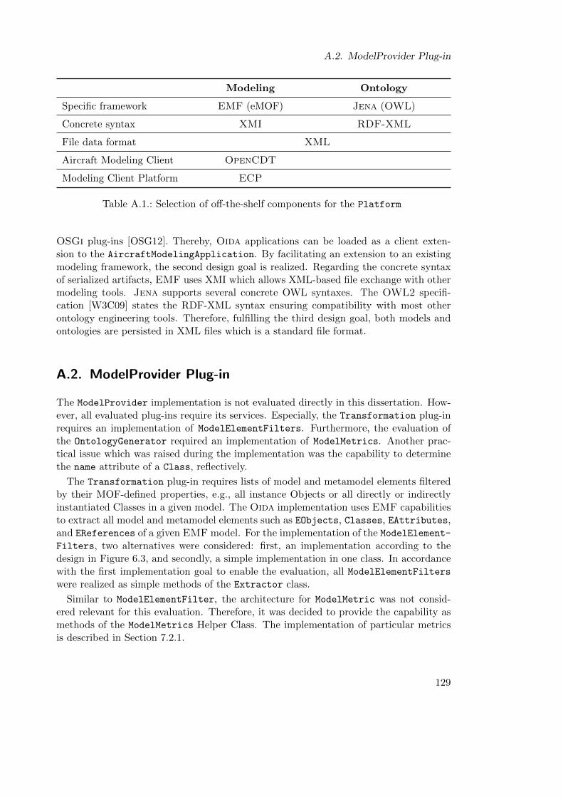
A.2. ModelProvider Plug-in
Modeling Ontology
Specific framework EMF (eMOF) Jena (OWL)
Concrete syntax XMI RDF-XML
File data format XML
Aircraft Modeling Client OpenCDT
Modeling Client Platform ECP
Table A.1.: Selection of off-the-shelf components for the Platform
OSGi plug-ins [OSG12]. Thereby, Oida applications can be loaded as a client exten-sion to the AircraftModelingApplication. By facilitating an extension to an existingmodeling framework, the second design goal is realized. Regarding the concrete syntaxof serialized artifacts, EMF uses XMI which allows XML-based file exchange with othermodeling tools. Jena supports several concrete OWL syntaxes. The OWL2 specifi-cation [W3C09] states the RDF-XML syntax ensuring compatibility with most otherontology engineering tools. Therefore, fulfilling the third design goal, both models andontologies are persisted in XML files which is a standard file format.
A.2. ModelProvider Plug-in
The ModelProvider implementation is not evaluated directly in this dissertation. How-ever, all evaluated plug-ins require its services. Especially, the Transformation plug-inrequires an implementation of ModelElementFilters. Furthermore, the evaluation ofthe OntologyGenerator required an implementation of ModelMetrics. Another prac-tical issue which was raised during the implementation was the capability to determinethe name attribute of a Class, reflectively.
The Transformation plug-in requires lists of model and metamodel elements filteredby their MOF-defined properties, e.g., all instance Objects or all directly or indirectlyinstantiated Classes in a given model. The Oida implementation uses EMF capabilitiesto extract all model and metamodel elements such as EObjects, Classes, EAttributes,and EReferences of a given EMF model. For the implementation of the ModelElement-Filters, two alternatives were considered: first, an implementation according to thedesign in Figure 6.3, and secondly, a simple implementation in one class. In accordancewith the first implementation goal to enable the evaluation, all ModelElementFilterswere realized as simple methods of the Extractor class.
Similar to ModelElementFilter, the architecture for ModelMetric was not consid-ered relevant for this evaluation. Therefore, it was decided to provide the capability asmethods of the ModelMetrics Helper Class. The implementation of particular metricsis described in Section 7.2.1.
129
A. Implementation of the Oida Prototype
For the matching of disciplineConcepts with the reference ontology, Oida mustgenerate a meaningful object identifier. Metamodel Designers usually specify a name at-tribute for this purpose. However, according to MOF the name attribute is not manda-tory for Objects. The ModelProvider implements the service to determine the name
using the reflection capabilities of EMF. Thereby, assigning the name attribute by userinterface as part of the Match Models use case or implementing a heuristic was con-sidered. The name attribute determination service is a prerequisite for the Ontology-
Generator. Therefore, the service must be available before the Matching initiates theMatch Models use case. Therefore, the name attribute determination service was im-plemented as heuristical method in ModelProvider. The heuristic is analogous to themethod used by the EMF.Edit generator [Ste+08]. In a first cycle, the heuristic looksfor an attribute called name using the reflection capabilities of EMF. If unsuccessful, asecond search looking for an attribute whose name includes name is performed. If stillunsuccessful, the Java object ID is returned. For the given sample models, this heuristicalways returned an accurate name attribute in the first cycle.
A.3. OntologyProvider Plug-in
The OntologyProvider plug-in serves as an adapter to the OntologyFramework, thusproviding an ontology repository to higher layer plug-ins. In particular, the Transfor-
mation plug-in requires an adapter to an InferenceModel implementation. Accordingto the design in Figure 6.4 the OntologyProvider also provides implementations of theOntologyFilter and OntologyMetric interfaces.
The implementation of the OntologyFrameworkAdapter classes could be made withonly minor adaptions as Jena directly provides most of the required classes and methods.To give an example of an adaption, unlike EMF, Jena methods return multiple objectsas iterators instead of lists.
The implementation of the InferenceModelAdapter was carried out and tested withthe Jena standard reasoner on small artificial models. The design of the Oida frame-work and, in particular, the SemanticValidator of the Matching component is based onthe assumption that an automated Reasoner requires less than 3 seconds to determineontology consistency and to produce a meaningful report if an inconsistency is detected.However, a complete classification cycle with more realistic ontologies generated fromthe sample models required considerably more than 3 seconds. The evaluation strategyis focused rather on the feasibility of an interactive Match Models use case than on thevalidation of particular automated KnowledgeSources. Therefore, it was decided to useProtege via file exchange as an external tool for ontology validation and maintenance.Thereby, the automated integrated reasoning capability was traded with an external ap-plication which allows validation of Oida ontologies offline, testing a variety of reasonerslike Pellet [Sir+07] or HermiT [SMH08]. The file exchange was facilitated by the im-plementation of the OntologyFileHandler adapter which was realized as a HelperClass.Similar to the ModelProvider plug-in, a simplified implementation of OntologyMetricswas chosen, which is described in more detail in Section 7.2.1.
130
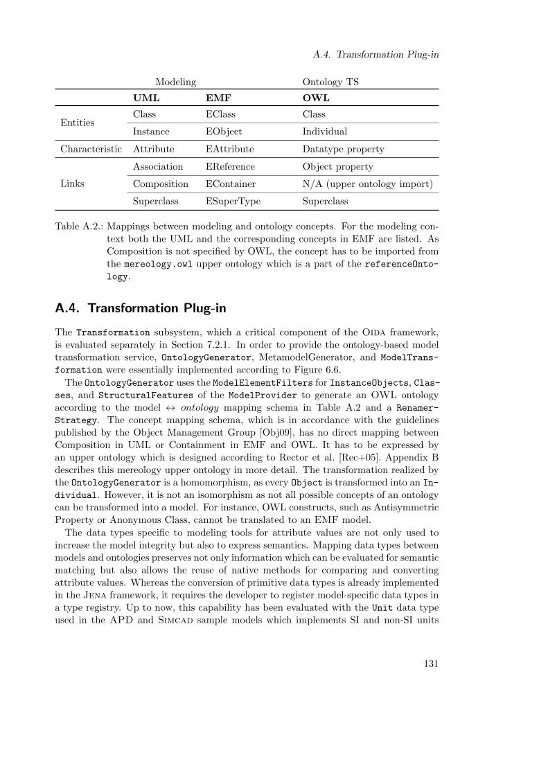
A.4. Transformation Plug-in
Modeling Ontology TS
UML EMF OWL
EntitiesClass EClass Class
Instance EObject Individual
Characteristic Attribute EAttribute Datatype property
Links
Association EReference Object property
Composition EContainer N/A (upper ontology import)
Superclass ESuperType Superclass
Table A.2.: Mappings between modeling and ontology concepts. For the modeling con-text both the UML and the corresponding concepts in EMF are listed. AsComposition is not specified by OWL, the concept has to be imported fromthe mereology.owl upper ontology which is a part of the referenceOnto-
logy.
A.4. Transformation Plug-in
The Transformation subsystem, which a critical component of the Oida framework,is evaluated separately in Section 7.2.1. In order to provide the ontology-based modeltransformation service, OntologyGenerator, MetamodelGenerator, and ModelTrans-
formation were essentially implemented according to Figure 6.6.
The OntologyGenerator uses the ModelElementFilters for InstanceObjects, Clas-ses, and StructuralFeatures of the ModelProvider to generate an OWL ontologyaccording to the model ↔ ontology mapping schema in Table A.2 and a Renamer-
Strategy. The concept mapping schema, which is in accordance with the guidelinespublished by the Object Management Group [Obj09], has no direct mapping betweenComposition in UML or Containment in EMF and OWL. It has to be expressed byan upper ontology which is designed according to Rector et al. [Rec+05]. Appendix Bdescribes this mereology upper ontology in more detail. The transformation realized bythe OntologyGenerator is a homomorphism, as every Object is transformed into an In-
dividual. However, it is not an isomorphism as not all possible concepts of an ontologycan be transformed into a model. For instance, OWL constructs, such as AntisymmetricProperty or Anonymous Class, cannot be translated to an EMF model.
The data types specific to modeling tools for attribute values are not only used toincrease the model integrity but also to express semantics. Mapping data types betweenmodels and ontologies preserves not only information which can be evaluated for semanticmatching but also allows the reuse of native methods for comparing and convertingattribute values. Whereas the conversion of primitive data types is already implementedin the Jena framework, it requires the developer to register model-specific data types ina type registry. Up to now, this capability has been evaluated with the Unit data typeused in the APD and Simcad sample models which implements SI and non-SI units
131
A. Implementation of the Oida Prototype
of measures. OWL does not offer special data types but uses the data types definedin the XML Schema Definition (XSD). The first prototype of the OntologyGenerator
translated domain-specific values of data types not covered by the Jena frameworkto a String representation. However, this implementation did not allow adoption ofdiscipline-specific data types to the referenceOntology. Furthermore, it hindered thereuse of implementations of type-specific methods determining equality. For instance,the Unit class used in the APD and Simcad sample metamodels allows conversionbetween different units of measure. Therefore, the Transformations between modelsand ontologies such as the OntologyGenerator and the MetamodelGenerator implementan adapter to the capabilities of the Jena framework. Jena provides a bidirectional typemapping registry which allows registering user-defined data types by ad hoc creation ofnon-standard data types in an ontology .
One of the core features of the Oida framework is the matching of objects which rep-resent the same physical object. This capability is realized by the OntologyGenerator
transforming EMF models to OWL ontologies. However, both EMF and OWL havedifferent concepts of object identity. Basically, an OWL ontology is a set of statementsabout OntologyResources and their relations to each other. Thereby, every Ontology-
Resource has a Unified Resource Identifier (URI). According to the design requirementfor an injective model-to-model mapping, a renaming schema must generate a uniqueURI for every Object. The URI should be readable for humans to allow low level on-tology maintenance and plausibility checks. In that sense a URI such as http://bhl.
net/aircraft.owl#wingspan is preferable to http://bhl.net/aircraft.owl#105154.Therefore, the implementation of a suitable RenamerStrategy was based on three as-sumptions. First, that almost every object has a name attribute; secondly, that thevalue of the name attribute of a model element indicates its meaning; and thirdly, thatthe value of the name attribute of its container object indicates the context. EMF stip-ulates that every metamodel element like EClass, EAttribute, and EReference has aname attribute which informally indicates the semantics of the metamodel element com-prehensible for the developer. Instances of EObject, which is the root class of ECore,do not have a specified name attribute. Therefore, RenamerStrategy implementationsuse the name attribute heuristic of the ModelProvider. Furthermore, in EMF everyEObject provides an EContainer reference which allows navigation of the containmenttree of a model. Taking Object Identity, name attribute value, and EContainer ref-erences as sources, three alternatives for a RenamerStrategy were considered duringimplementation:
ClassName:ObjectName Whereas in EMF the name of a class is unambiguous in acertain name space, its combination with the object name is ambiguous in EMF, as theobject name is an arbitrary user-defined attribute which in a valid model can be usedmore than once. Furthermore, this renaming schema abandons the context within themodel and provides no version information about the object.
132
A.4. Transformation Plug-in
Object Identity The Object Identity is unambiguous within a runtime environment(see Section 2.1) However, the Object Identity deliberately abandons the conceptual andstructural context. Accordingly, it does not represent the semantic identity of an object.Furthermore, an Object Identity which is unreadable for humans makes interactive lowlevel ontology maintenance and engineering impossible.
ContainerName.ObjectName This renaming schema includes the context of the ob-ject. Furthermore, after a first manual inspection of the sample models, it was consideredto be unambiguous for the given models. Therefore, this RenamerStrategy was imple-mented in the Oida framework.
The decision for the selection of a RenamerStrategy was based on the necessity ofthe development process to inspect the ontologies in order to verify the algorithms.Therefore, the ContainerName.ObjectName strategy was considered the most adept al-ternative. Consequently, the implementation of this RenamerStrategy was used in theevaluation described in Section 7.2.1, Section 7.2.2, and Section 7.2.3. The evaluation ofthe transformation TMO described in Section 7.2.1, however, revealed that the first con-tainer level is sufficient to rename model EAttributes and EReferences unambiguouslybut not to rename EObjects.
The MetamodelGenerator creates the referenceMetamodel from the referenceOn-
tology using the mapping schema shown in Table A.2 and the type mapping capabilityas used by the OntologyGenerator, but in the opposite direction. The implementa-tion not only employs OntologyFilters to iterate through different kinds of referenceconcepts but also uses the capability of the EMF framework to dynamically generatea metamodel. In contrast to the OntologyGenerator, MetamodelGenerator uses thelocal name suffix of the URI for naming metamodel elements, as the URI is unique bydefinition.
The ModelTransformation in Figure 6.6 transforms a disciplineModel with seman-tically overlapping content to a common metamodel. Performing this transformation twodisciplineModels, conforming to different metamodels, can be compared and mergedusing existing metamodel-based frameworks. The implementation of ModelTransfor-
mation is based on the assumption that the direct model-to-model transformation can bedetermined indirectly by the equivalence statements between instance and metaconceptsof disciplineOntology, derived from the disciplineModel to the referenceOntolo-
gy.
This transformation is a homomorphism regarding the model representation of EOb-
jects, EClasses, and EAttributes. The Oida framework disregards behavior and linksof entities to other entities. Accordingly, the Oida framework is neither able to detectconflicts of these model element features nor does it support their migration from onemodel to the other. During th runtime of the Transformation plug-in, the ModelTrans-formation stores the mapping between each disciplineObject and referenceObject
in a mapping model. According to its design, the ObjectMapping also contains a map-
133
A. Implementation of the Oida Prototype
ping between disciplineClass and referenceClass and the respective Attributes.Thereby, every discipline-specific object can be mapped to a reference classifier, inde-pendent of the mapping its discipline-specific classifier as long as ontology consistencyis maintained. The ObjectMapping data model has been specified as an Ecore modeland generated using the EMF code generator.
The capability of the Transformation plug-in to map between data types which areused by the OntologyGenerator and MetamodelGenerator, is basically an adapter toexisting Jena features. The implementation of the ModelTransformation extends thiscapability by ontology-based type conversion which is required to merge attribute valuesfrom different but related data types. For instance, in the Simcad sample model, theattribute representing the number of passengers is a Double type variable, whereas inAPA the same concept is an Integer type variable. Java supports implicit type castingfrom Integer to Double. The reverse operation requires the Model Owner’s declarationthat the number of passengers is always an Integer value disregarding the range of theconcrete data type in the disciplineModels. If the attribute transformation algorithmdoes not find the data type of the source attribute in the target attribute, it queriesthe referenceOntology for another type representing a larger number set. This wouldallow implicit type casting. If this is not successful, it queries the referenceOntology
for a data type representing the next smaller number set which would allow numberconversion. If this is still not successful, the target attribute value is not set. However,the type conversion method only implements the conversions required for the samplemodels and emits a warning of potential data loss if implicit type casting is not applicable.
The mapping between the source and the target of ModelTransformation can bedeleted after the Merge Models Partially use case as they are not required during theruntime of the Transformation plug-in. Thereby, the amount of redundant coupledartifacts is reduced.
A.5. Matching Plug-in
The design of the Matching features a Blackboard pattern which is based on theassumption that simple automated heuristics and algorithms can contribute to partialsolutions which are aggregated and exchanged via the Blackboard and orchestratedby the BlackboardControl. The design stipulates three KnowledgeSources: Name-
EquivalenceFinder, StructuralEquivalenceFinder, and SemanticValidator. Dueto the previous experience with the implementation of the InferenceModel, it wasdecided to first develop and evaluate each potential KnowledgeSource for the samplemodels, before tackling the implementation of the Blackboard pattern.
The design NameEquivalenceFinder is based on the assumption that if objects havethe same name they most probably represent the same thing. The capability was de-veloped and tested with artificial aircraft model data. However, tests with sample datarevealed no directly matching names between the referenceOntology and the disci-
plineOntologies. Therefore, this knowledge source was considered ineffective for theevaluation.
134
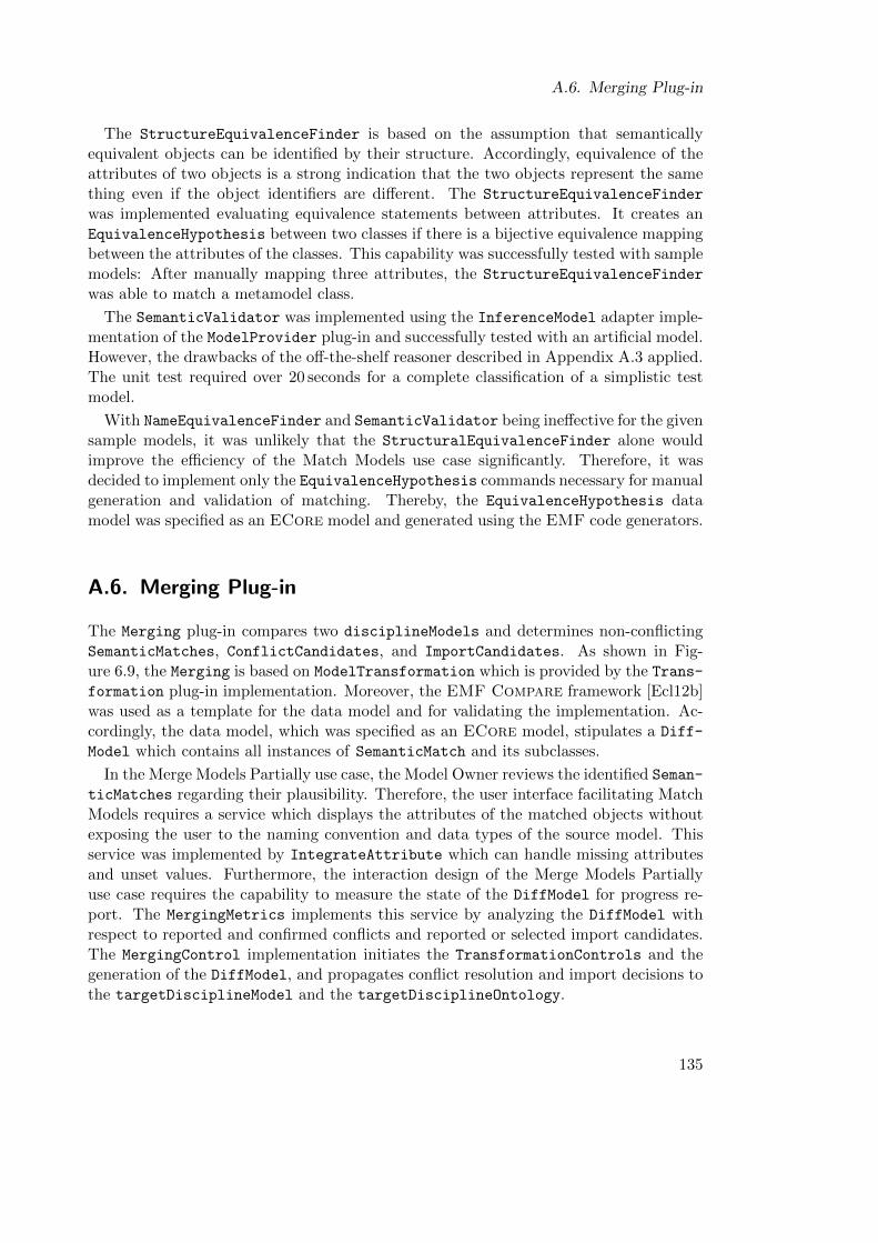
A.6. Merging Plug-in
The StructureEquivalenceFinder is based on the assumption that semanticallyequivalent objects can be identified by their structure. Accordingly, equivalence of theattributes of two objects is a strong indication that the two objects represent the samething even if the object identifiers are different. The StructureEquivalenceFinder
was implemented evaluating equivalence statements between attributes. It creates anEquivalenceHypothesis between two classes if there is a bijective equivalence mappingbetween the attributes of the classes. This capability was successfully tested with samplemodels: After manually mapping three attributes, the StructureEquivalenceFinder
was able to match a metamodel class.
The SemanticValidator was implemented using the InferenceModel adapter imple-mentation of the ModelProvider plug-in and successfully tested with an artificial model.However, the drawbacks of the off-the-shelf reasoner described in Appendix A.3 applied.The unit test required over 20 seconds for a complete classification of a simplistic testmodel.
With NameEquivalenceFinder and SemanticValidator being ineffective for the givensample models, it was unlikely that the StructuralEquivalenceFinder alone wouldimprove the efficiency of the Match Models use case significantly. Therefore, it wasdecided to implement only the EquivalenceHypothesis commands necessary for manualgeneration and validation of matching. Thereby, the EquivalenceHypothesis datamodel was specified as an ECore model and generated using the EMF code generators.
A.6. Merging Plug-in
The Merging plug-in compares two disciplineModels and determines non-conflictingSemanticMatches, ConflictCandidates, and ImportCandidates. As shown in Fig-ure 6.9, the Merging is based on ModelTransformation which is provided by the Trans-formation plug-in implementation. Moreover, the EMF Compare framework [Ecl12b]was used as a template for the data model and for validating the implementation. Ac-cordingly, the data model, which was specified as an ECore model, stipulates a Diff-
Model which contains all instances of SemanticMatch and its subclasses.
In the Merge Models Partially use case, the Model Owner reviews the identified Seman-
ticMatches regarding their plausibility. Therefore, the user interface facilitating MatchModels requires a service which displays the attributes of the matched objects withoutexposing the user to the naming convention and data types of the source model. Thisservice was implemented by IntegrateAttribute which can handle missing attributesand unset values. Furthermore, the interaction design of the Merge Models Partiallyuse case requires the capability to measure the state of the DiffModel for progress re-port. The MergingMetrics implements this service by analyzing the DiffModel withrespect to reported and confirmed conflicts and reported or selected import candidates.The MergingControl implementation initiates the TransformationControls and thegeneration of the DiffModel, and propagates conflict resolution and import decisions tothe targetDisciplineModel and the targetDisciplineOntology.
135
A. Implementation of the Oida Prototype
A.7. Evolution Plug-in
The Evolution plug-in facilitates the Co-Evolution capability of the Oida framework.According to the design depicted in Figure 6.10, this capability is accomplished by twokinds of KnowledgeSources: EvolutionAlgorithm and EvolutionHeuristic. How-ever, due to the ineffectiveness of most automated KnowledgeSources the Black-board pattern was not implemented. Therefore, EvolutionAlgorithm and Evolution-
Heuristic have been implemented as automated preprocessors to the manual MatchModels use case. These classes are described in detail in Section 7.2.4.
A.8. MatchingApp Plug-in
The purpose of the MatchingApp plug-in is to provide a user interface for the MatchModels process. According to the design in Figure 6.13, the plug-in implements theManualEquivalenceCreator and the EquivalenceReviewForm as KnowledgeSource.As the Blackboard pattern was implemented, these classes are directly controlledby the MatchingAppControl. The MatchingApp plug-in is started by the implementa-tion of an ECP ModelElementOpener. When the MatchingApp plug-in is loaded to theAircraftModelingApplication, the underlying ECP framework lets the Model Ownerselect the disciplineSpecificRootObject in his model and start the MatchingApp viaa context menu.
The ExtendingMatchingEditor integrates the ManualEquivalenceCreator and theEquivalenceReviewForm. During the initialization of the Editor the ImportPrevi-
ousMappingsDialog is shown, which allows the user to load an OWL file which containsequivalence statements from a previous Match Models session. This dialog controls anImportPreviousMappings instance of the Evolution plug-in.
When the import is complete, the user interface depicted in Figure A.1 is displayed.This Editor is implemented reusing the JFace and the SWT framework provided byECP. Thereby, the Model Owner experiences a look-and-feel he is familiar with fromthe Aircraft Modeling Platform. If the Model Owner does not find the appropri-ate referenceOntologyResource during the Match Models use case, he can select thedisciplineOntologyResource and click the “Add Reference” button to open a Cre-
ateReferenceResourceDialog where the appropriate name for the new referenceOn-
tologyResource can be entered. When the user confirms the dialog, the defined re-source is created in the referenceOntology and an equivalence statement is added tothe disciplineOntologyResource. Upon returning to the ExtendingMatchingEdi-
tor, the user cannot only save the mapped disciplineOntology but also the extendedreferenceOntology to an OWL XML file.
The Extending Matching Editor serves as a demonstrator for a user interface whichintegrates the Oida framework capabilities which supports the Match Models and Co-Evolve Integration Artifacts use cases. For the evaluation of the Match Models use casea special implementation of the MatchingEditor was used which does not allow the
136
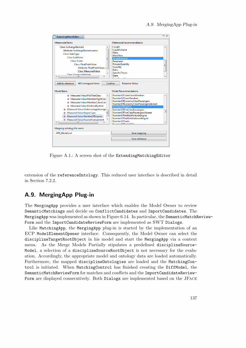
A.9. MergingApp Plug-in
Figure A.1.: A screen shot of the ExtendingMatchingEditor
extension of the referenceOntology. This reduced user interface is described in detailin Section 7.2.2.
A.9. MergingApp Plug-in
The MergingApp provides a user interface which enables the Model Owner to reviewSemanticMatchings and decide on ConflictCandidates and ImportCandidates. TheMergingApp was implemented as shown in Figure 6.14. In particular, the SemanticMatchReview-Form and the ImportCandidateReviewForm are implemented as SWT Dialogs.
Like MatchingApp, the MergingApp plug-in is started by the implementation of anECP ModelElementOpener interface. Consequently, the Model Owner can select thedisciplineTargetRootObject in his model and start the MergingApp via a contextmenu. As the Merge Models Partially stipulates a predefined disciplineSource-
Model, a selection of a disciplineSourceRootObject is not necessary for the evalu-ation. Accordingly, the appropriate model and ontology data are loaded automatically.Furthermore, the mapped disciplineOntologies are loaded and the MatchingCon-
trol is initiated. When MatchingControl has finished creating the DiffModel, theSemanticMatchReviewForm for matches and conflicts and the ImportCandidateReview-Form are displayed consecutively. Both Dialogs are implemented based on the JFace
137
A. Implementation of the Oida Prototype
and SWT framework. In particular, the Dialogs use the IntegratedAttribute classof the Merging plug-in to provide a consistent view of the incoming model data tosupport the user in assessing the plausibility of the matching results. The Semantic-
MatchReviewForm displays the detected SemanticMatches and ConflictCandidates
and receives the user’s confirmation or report on implausible matches. Thereby, confir-mation of a ConflictCandidate is interpreted as a user decision to resolve the conflict.Accordingly, when the user pushes the button labeled “Next” to conclude the Dialog,the MergingControl resolves the conflict immediately and the ImportCandidateRe-
viewForm instance is opened.
MigrateDialog
The ImportCandidateReviewForm is the user interface to MergingControl which facil-itates the interactive process of the Migrate Model Parts use case. The Dialog depictedin Figure A.3 displays ImportCandidates. The Model Owner can either discard a pro-posed ImportCandidate or select it for import. In the first case, he can give an additionalreview comment. In the latter case, he can define an appropriate disciplineSpeci-
ficName and disciplineSpecificContainer object for the respective model elementselected for import in order to integrate the elements in the naming convention anddecomposition strategy specific to the target model. The possible containers are shownin a ContainerNavigatorForm which is integrated on the left side of the ImportCandi-
dates dialog. The UI also provides the current attribute values of the selected modelelement, reusing IntegrateAttribute. The user concludes the dialog by pushing thefinish button and thereby triggers MergingControl to propagate the confirmed Import-
Candidates to the disciplineTargetModel and the disciplineTargetOntology.
138
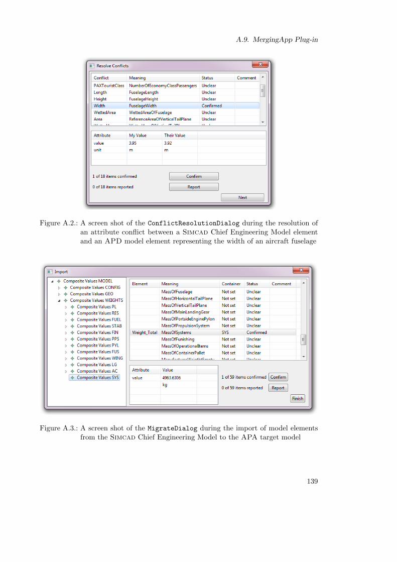
A.9. MergingApp Plug-in
Figure A.2.: A screen shot of the ConflictResolutionDialog during the resolution ofan attribute conflict between a Simcad Chief Engineering Model elementand an APD model element representing the width of an aircraft fuselage
Figure A.3.: A screen shot of the MigrateDialog during the import of model elementsfrom the Simcad Chief Engineering Model to the APA target model
139

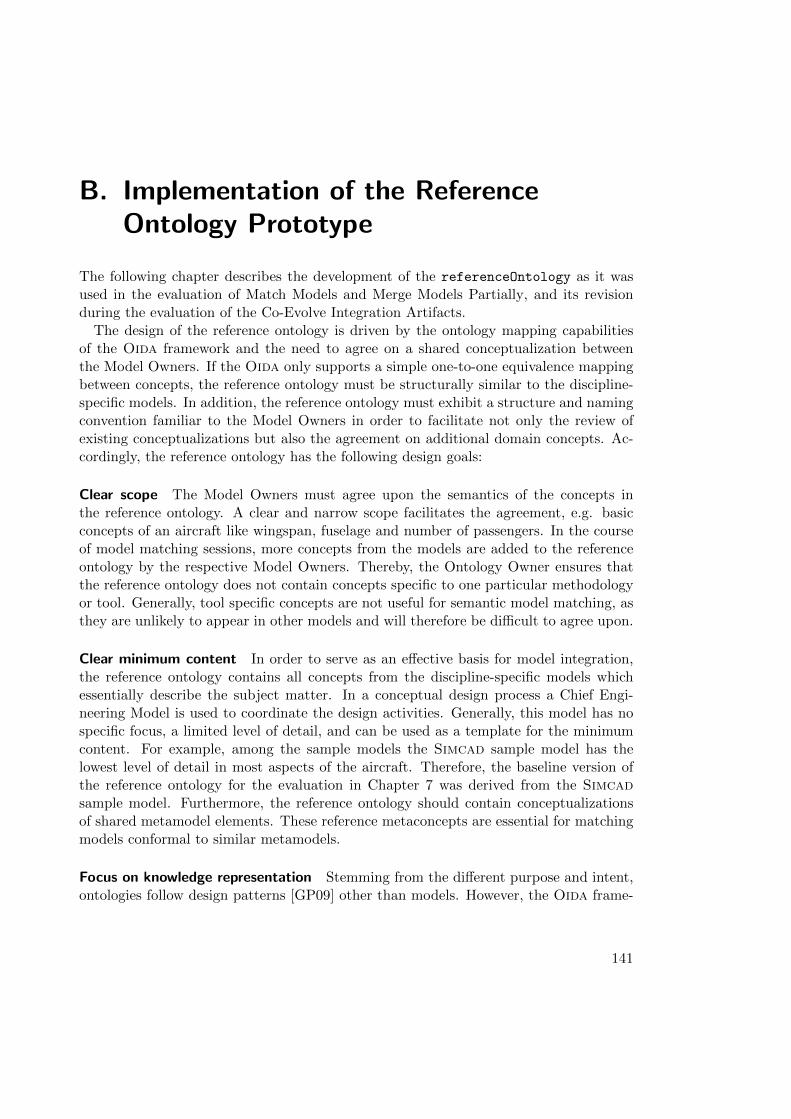
B. Implementation of the ReferenceOntology Prototype
The following chapter describes the development of the referenceOntology as it wasused in the evaluation of Match Models and Merge Models Partially, and its revisionduring the evaluation of the Co-Evolve Integration Artifacts.
The design of the reference ontology is driven by the ontology mapping capabilitiesof the Oida framework and the need to agree on a shared conceptualization betweenthe Model Owners. If the Oida only supports a simple one-to-one equivalence mappingbetween concepts, the reference ontology must be structurally similar to the discipline-specific models. In addition, the reference ontology must exhibit a structure and namingconvention familiar to the Model Owners in order to facilitate not only the review ofexisting conceptualizations but also the agreement on additional domain concepts. Ac-cordingly, the reference ontology has the following design goals:
Clear scope The Model Owners must agree upon the semantics of the concepts inthe reference ontology. A clear and narrow scope facilitates the agreement, e.g. basicconcepts of an aircraft like wingspan, fuselage and number of passengers. In the courseof model matching sessions, more concepts from the models are added to the referenceontology by the respective Model Owners. Thereby, the Ontology Owner ensures thatthe reference ontology does not contain concepts specific to one particular methodologyor tool. Generally, tool specific concepts are not useful for semantic model matching, asthey are unlikely to appear in other models and will therefore be difficult to agree upon.
Clear minimum content In order to serve as an effective basis for model integration,the reference ontology contains all concepts from the discipline-specific models whichessentially describe the subject matter. In a conceptual design process a Chief Engi-neering Model is used to coordinate the design activities. Generally, this model has nospecific focus, a limited level of detail, and can be used as a template for the minimumcontent. For example, among the sample models the Simcad sample model has thelowest level of detail in most aspects of the aircraft. Therefore, the baseline version ofthe reference ontology for the evaluation in Chapter 7 was derived from the Simcadsample model. Furthermore, the reference ontology should contain conceptualizationsof shared metamodel elements. These reference metaconcepts are essential for matchingmodels conformal to similar metamodels.
Focus on knowledge representation Stemming from the different purpose and intent,ontologies follow design patterns [GP09] other than models. However, the Oida frame-
141
B. Implementation of the Reference Ontology Prototype
work supports model owners in expanding the reference ontology by transferring entitiesand structures from source models to the reference ontology. The Ontology Owneris responsible for avoiding discipline-specific modeling design patterns in the referenceontology that are less suitable for knowledge representation and automated reasoning.
Based on standard upper ontologies The reference ontology should import fundamen-tal concepts of the application domain from standard upper ontologies. For instance,the domain of conceptual aircraft design is based on fundamental concepts like physicalquantities and units of measure which can be imported into the reference ontology fromexisting upper ontologies, such as the “Library for Quantity Kinds and Units” [Kon+11].This practice of modularization promotes the compatibility of the reference ontology toother domain ontology creation efforts.
The implementation of the referenceOntology was oriented towards the implemen-tation goals of Oida aiming at enabling the evaluation and maintaining independencefrom specific conceptual design tools. The trade-off between the primary purpose andthe design goals raised three issues regarding the scope of the referenceOntology, theminimum complexity, and which upper ontology to import.
As mentioned above in Section 1.2.4, the scope of the model integration process de-scribed in this dissertation has to do with the structural aspects of an aircraft. Thestructural description is very concrete compared to other aspects such as aircraft systembehavior. Therefore, the structural aspects are a good basis to expand the reference-
Ontology to other aspects.
The minimum level of detail mentioned in the referenceOntology design goals isa measure for the complexity of the referenceOntology, i.e. the number of entitiesand links between the entities. The demonstration of ontology-based model integrationrequired at least the coverage of the entities specified in the metamodels involved andthe objects of the master model. Preliminary analysis had shown that the Simcadsample model was most adept for serving as a Chief Engineering Model. Therefore,the first version used in the evaluation of Model Matching and Partial Model Mergewas simulated by the Ontology Owner with the Simcad sample model, starting withan initially empty referenceOntology. Subsequently, the referenceOntology wasextended by the Ontology Owner performing the Match Models use case with the APDsample model. The APA sample model was not included in the preparation process fortwo reasons. First, the naming convention of the APA sample model was very difficult tocomprehend for an Ontology Owner unfamiliar with the APA tool. Without the ModelOwner of APA it would have been difficult to determine the meaning of the conceptsand to decide whether the particular concept was within the scope of the referenceOn-
tology. Secondly, performing the Match Models use case with the APA sample modelusing a referenceOntology which was not prepared by the Ontology Owner allowedinvestigation of the consequences of such an incomplete reference to the efficiency anduser acceptance of the APA Model Owner.
142
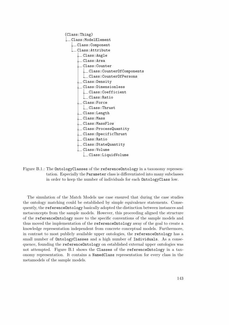
(Class:Thing)
Class:ModelElement
Class:Component
Class:Attribute
Class:Angle
Class:Area
Class:Counter
Class:CounterOfComponents
Class:CounterOfPersons
Class:Density
Class:Dimensionless
Class:Coefficient
Class:Ratio
Class:Force
Class:Thrust
Class:Length
Class:Mass
Class:MassFlow
Class:ProcessQuantity
Class:SpecificThrust
Class:Ratio
Class:StateQuantity
Class:Volume
Class:LiquidVolume
Figure B.1.: The OntologyClasses of the referenceOntology in a taxonomy represen-tation. Especially the Parameter class is differentiated into many subclassesin order to keep the number of individuals for each OntologyClass low.
The simulation of the Match Models use case ensured that during the case studiesthe ontology matching could be established by simple equivalence statements. Conse-quently, the referenceOntology basically adopted the distinction between instances andmetaconcepts from the sample models. However, this proceeding aligned the structureof the referenceOntology more to the specific conventions of the sample models andthus moved the implementation of the referenceOntology away of the goal to create aknowledge representation independent from concrete conceptual models. Furthermore,in contrast to most publicly available upper ontologies, the referenceOntology has asmall number of OntologyClasses and a high number of Individuals. As a conse-quence, founding the referenceOntology on established external upper ontologies wasnot attempted. Figure B.1 shows the Classes of the referenceOntology in a tax-onomy representation. It contains a NamedClass representation for every class in themetamodels of the sample models.
143
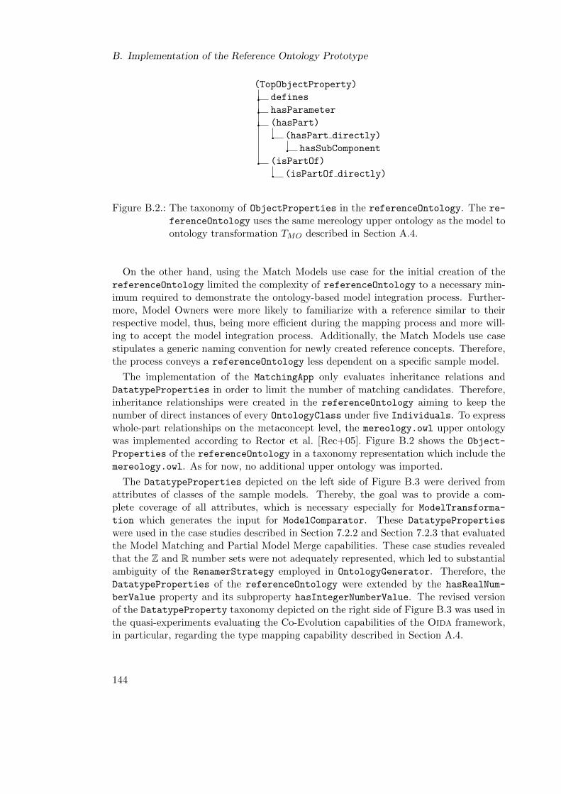
B. Implementation of the Reference Ontology Prototype
(TopObjectProperty)
defines
hasParameter
(hasPart)
(hasPart directly)
hasSubComponent
(isPartOf)
(isPartOf directly)
Figure B.2.: The taxonomy of ObjectProperties in the referenceOntology. The re-
ferenceOntology uses the same mereology upper ontology as the model toontology transformation TMO described in Section A.4.
On the other hand, using the Match Models use case for the initial creation of thereferenceOntology limited the complexity of referenceOntology to a necessary min-imum required to demonstrate the ontology-based model integration process. Further-more, Model Owners were more likely to familiarize with a reference similar to theirrespective model, thus, being more efficient during the mapping process and more will-ing to accept the model integration process. Additionally, the Match Models use casestipulates a generic naming convention for newly created reference concepts. Therefore,the process conveys a referenceOntology less dependent on a specific sample model.
The implementation of the MatchingApp only evaluates inheritance relations andDatatypeProperties in order to limit the number of matching candidates. Therefore,inheritance relationships were created in the referenceOntology aiming to keep thenumber of direct instances of every OntologyClass under five Individuals. To expresswhole-part relationships on the metaconcept level, the mereology.owl upper ontologywas implemented according to Rector et al. [Rec+05]. Figure B.2 shows the Object-
Properties of the referenceOntology in a taxonomy representation which include themereology.owl. As for now, no additional upper ontology was imported.
The DatatypeProperties depicted on the left side of Figure B.3 were derived fromattributes of classes of the sample models. Thereby, the goal was to provide a com-plete coverage of all attributes, which is necessary especially for ModelTransforma-
tion which generates the input for ModelComparator. These DatatypeProperties
were used in the case studies described in Section 7.2.2 and Section 7.2.3 that evaluatedthe Model Matching and Partial Model Merge capabilities. These case studies revealedthat the Z and R number sets were not adequately represented, which led to substantialambiguity of the RenamerStrategy employed in OntologyGenerator. Therefore, theDatatypeProperties of the referenceOntology were extended by the hasRealNum-
berValue property and its subproperty hasIntegerNumberValue. The revised versionof the DatatypeProperty taxonomy depicted on the right side of Figure B.3 was used inthe quasi-experiments evaluating the Co-Evolution capabilities of the Oida framework,in particular, regarding the type mapping capability described in Section A.4.
144
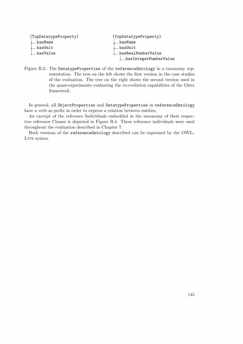
(TopDatatypeProperty)
hasName
hasUnit
hasValue
(TopDatatypeProperty)
hasName
hasUnit
hasRealNumberValue
hasIntegerNumberValue
Figure B.3.: The DatatypeProperties of the referenceOntology in a taxonomy rep-resentation. The tree on the left shows the first version in the case studiesof the evaluation. The tree on the right shows the second version used inthe quasi-experiments evaluating the co-evolution capabilities of the Oidaframework.
In general, all ObjectProperties and DatatypeProperties in referenceOntology
have a verb as prefix in order to express a relation between entities.An excerpt of the reference Individuals embedded in the taxonomy of their respec-
tive reference Classes is depicted in Figure B.4. These reference individuals were usedthroughout the evaluation described in Chapter 7.
Both versions of the referenceOntology described can be expressed by the OWL-Lite syntax.
145
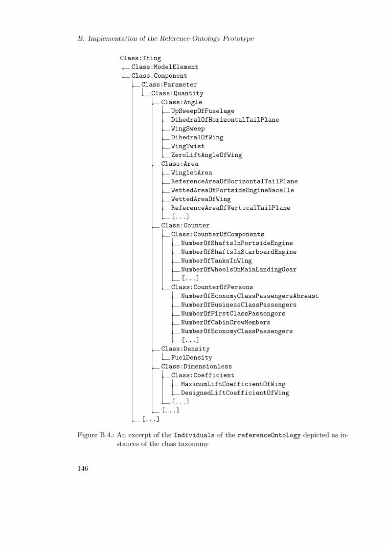
B. Implementation of the Reference Ontology Prototype
Class:Thing
Class:ModelElement
Class:Component
Class:Parameter
Class:Quantity
Class:Angle
UpSweepOfFuselage
DihedralOfHorizontalTailPlane
WingSweep
DihedralOfWing
WingTwist
ZeroLiftAngleOfWing
Class:Area
WingletArea
ReferenceAreaOfHorizontalTailPlane
WettedAreaOfPortsideEngineNacelle
WettedAreaOfWing
ReferenceAreaOfVerticalTailPlane
[...]
Class:Counter
Class:CounterOfComponents
NumberOfShaftsInPortsideEngine
NumberOfShaftsInStarboardEngine
NumberOfTanksInWing
NumberOfWheelsOnMainLandingGear
[...]
Class:CounterOfPersons
NumberOfEconomyClassPassengersAbreast
NumberOfBusinessClassPassengers
NumberOfFirstClassPassengers
NumberOfCabinCrewMembers
NumberOfEconomyClassPassengers
[...]
Class:Density
FuelDensity
Class:Dimensionless
Class:Coefficient
MaximumLiftCoefficientOfWing
DesignedLiftCoefficientOfWing
[...]
[...]
[...]
Figure B.4.: An excerpt of the Individuals of the referenceOntology depicted as in-stances of the class taxonomy
146
List of Figures
1.1. Aircraft conceptual design process . . . . . . . . . . . . . . . . . . . . . . 2
1.2. Diagram of the top-level use cases . . . . . . . . . . . . . . . . . . . . . . 6
1.3. Data flow relations between Oida artifacts . . . . . . . . . . . . . . . . . 11
3.1. Excerpt from conceptual aircraft model . . . . . . . . . . . . . . . . . . . 22
4.1. Model matching based on a common metamodel . . . . . . . . . . . . . . 31
4.2. Implicit metamodel separation . . . . . . . . . . . . . . . . . . . . . . . . 32
4.3. Ontology-based model matching . . . . . . . . . . . . . . . . . . . . . . . 32
4.4. Diagram of Match Models use cases . . . . . . . . . . . . . . . . . . . . . 35
4.5. Flow of events of the Match Models use case . . . . . . . . . . . . . . . . 36
4.6. Description of the Match Models use case . . . . . . . . . . . . . . . . . . 37
4.6. Description of the Match Models use case (continued) . . . . . . . . . . . 38
4.7. Diagram of the Merge Models Partially use cases . . . . . . . . . . . . . . 40
4.8. Flow of events of the Merge Models Partially use case . . . . . . . . . . . 42
4.9. Description of the Merge Models Partially use case . . . . . . . . . . . . . 43
4.9. Description of the Merge Models Partially use case (continued) . . . . . . 44
4.10. Diagram of Co-Evolve Integration Artifacts use cases . . . . . . . . . . . . 46
4.11. Diagram of the Co-Evolve Integration Artifacts use cases . . . . . . . . . 49
4.12. Description of Co-Evolve Integration Artifacts use case . . . . . . . . . . . 50
5.1. Diagram of Entity Objects of the Match Models use case . . . . . . . . . . 53
5.2. Diagram of Boundary Objects of Match Models use case . . . . . . . . . . 55
5.3. Diagram of Control Object of the Match Models . . . . . . . . . . . . . . 56
5.4. Diagram of Entity Objects of the ontology-based model transformation TM 57
5.5. Diagram of Control Object of the ontology-based model transformation TM 58
5.6. Diagram of Entity Objects of the Merge Models Partially use case . . . . 61
5.7. Diagram of Boundary Objects of Merge Models Partially use case . . . . . 64
5.8. Diagram of Control Objects of the Merge Models Partially use case . . . . 65
5.9. Diagram of Entity Objects of the Co-Evolve Integration Artifacts use case 67
5.10. Diagram of Control Objects of the Co-Evolve Integration Artifacts . . . . 69
6.1. Component diagram of the Oida framework architecture . . . . . . . . . . 73
6.2. Class diagram of Platform layer . . . . . . . . . . . . . . . . . . . . . . . 74
6.3. Class diagram of ModelProvider subsystem . . . . . . . . . . . . . . . . . 76
6.4. Class diagram of OntologyProvider subsytem . . . . . . . . . . . . . . . 77
6.5. Class diagram OntologyResources adapter interfaces . . . . . . . . . . . 78
147
List of Figures
6.6. Class diagram Transformation subsystem . . . . . . . . . . . . . . . . . . 816.7. Class diagram of the Matching subsystem . . . . . . . . . . . . . . . . . . 836.8. Matching knowledge sources . . . . . . . . . . . . . . . . . . . . . . . . . . 846.9. Class diagram of the Merging subsystem . . . . . . . . . . . . . . . . . . . 866.10. Class diagram of the Evolution subsystem . . . . . . . . . . . . . . . . . 886.11. Evolution knowledge sources . . . . . . . . . . . . . . . . . . . . . . . . . 896.12. MatchingApp knowledge sources . . . . . . . . . . . . . . . . . . . . . . . . 916.13. Class diagram of the MatchingApp application . . . . . . . . . . . . . . . 926.14. Class diagram of the Merginging App application . . . . . . . . . . . . . 936.15. Oida knowledge sources overview . . . . . . . . . . . . . . . . . . . . . . . 95
7.1. Screen shot of the MatchingEditor . . . . . . . . . . . . . . . . . . . . . . 107
A.1. Screen shot of the ExtendingMatchingEditor . . . . . . . . . . . . . . . . 137A.2. Screen shot of the ConflictResolutionDialog . . . . . . . . . . . . . . 139A.3. Screen shot of the MigrateDialog . . . . . . . . . . . . . . . . . . . . . . 139
B.1. Taxonomy of reference OntologyClasses . . . . . . . . . . . . . . . . . . 143B.2. Taxonomy of reference ObjectProperties . . . . . . . . . . . . . . . . . . 144B.3. Taxonomy of reference DatatypeProperties . . . . . . . . . . . . . . . . 145B.4. Taxonomy of reference Individuals . . . . . . . . . . . . . . . . . . . . . 146
148
List of Tables
2.1. Six kinds of composition . . . . . . . . . . . . . . . . . . . . . . . . . . . . 16
5.1. Definitions of Entity Objects of the Match Models usecase . . . . . . . . . 545.2. Definitions of Boundary Objects of the Match Models use case . . . . . . 555.3. Definition of the Control Objects of the Match Models use case . . . . . . 565.4. Definition of Entity Objects of the ontology-based model transformation . 595.5. Definitions of Control Objects of the Merge Models Partially use case . . 595.6. Definitions of Entity Objects of the Merge Models Partially use case . . . 625.6. Definitions of Entity Objects of the Merge Models Partially (continued) . 635.7. Definitions of Boundary Objects of the Merge Models Partially use case . 635.8. Definition Control Object of the Merge Models Partially use case . . . . . 645.9. Definitions of Entity Objects of the Co-Evolve Integration Artifacts . . . 685.10. Definitions of Control Objects of the Co-Evolve Integration Artifacts . . . 69
6.1. Definitions of Oida KnowledgeSources . . . . . . . . . . . . . . . . . . . 94
7.1. Overview of the Oida evaluation . . . . . . . . . . . . . . . . . . . . . . . 1007.2. Measurements from quasi-experiments QE 1.1, QE 1.2, and QE 1.3 . . . . 1037.3. Efficiency rating scale . . . . . . . . . . . . . . . . . . . . . . . . . . . . . 1057.4. Measurements from case studies evaluating Model Matching . . . . . . . . 1097.5. Measurements from case studies evaluating Partial Model Merge . . . . . 1157.6. Measurements from quasi-experiment QE 2.1 . . . . . . . . . . . . . . . . 1197.7. Measurements from quasi-experiment QE 2.2 . . . . . . . . . . . . . . . . 119
A.1. Selection of off-the-shelf components for the Platform . . . . . . . . . . . 129A.2. Mappings between modeling and ontology metaconcepts . . . . . . . . . . 131
149

Bibliography
[Ada84] John G. Adair. “The Hawthorne effect: A reconsideration of the method-ological artifact.” In: Journal of Applied Psychology 69.2 (1984), p. 334.
[AK03] Colin Atkinson and Thomas Kuhne. “Model-Driven Development: A Meta-modeling Foundation”. In: Software, IEEE 20.5 (Sept. 2003), pp. 36 –41.
[BHS07] Frank Buschmann, Kevlin Henney, and Douglas C. Schmidt. Pattern-OrientedSoftware Architecture: A Pattern Language for Distributed Computing. 1st ed.Vol. 4. John Wiley & Sons, 2007.
[BHS08] Franz Baader, Ian Horrocks, and Ulrike Sattler. “Description Logics”. In:Handbook of Knowledge Representation. Ed. by Frank van Harmelen, VladimirLifschitz, and Bruce Porter. Vol. 3. Foundations of Artificial Intelligence. El-sevier, 2008, pp. 135 –179.
[Boh12] Daniel Bohnke. CPACS – A Common Language for Aircraft Design. Apr.2012. url: http://software.dlr.de/p/cpacs/home/.
[Bru+06] Greg Brunet, Marsha Chechik, Steve Easterbrook, Shiva Nejati, Nan Niu,and Mehrdad Sabetzadeh. A Manifesto for Model Merging. Shanghai, China,2006.
[DFV07] Marcos Didonet Del Fabro and Patrick Valduriez. “Semi-automatic ModelIntegration using Matching Transformations and Weaving Models”. In: Pro-ceedings of the 2007 ACM symposium on Applied computing. SAC ’07. ACM,2007, pp. 963–970.
[Dil88] Craig Dilworth. “Identity, Equality and Equivalence”. In: Dialectica 42.2(1988), pp. 83–92.
[Doa+03] AnHai Doan, Jayant Madhavan, Robin Dhamankar, Pedro Domingos, andAlon Halevy. “Learning to Match Ontologies on the Semantic Web”. In:The VLDB Journal 12 (4 2003), pp. 303–319.
[Ecl12a] Eclipse Foundation. EMF Client Platform project home. 2012. url: http://eclipse.org/emfclient/.
[Ecl12b] Eclipse Foundation. EMF Compare. 2012. url: http://eclipse.org/
emfcompare/.
[Fel10] Christiane Fellbaum. “WordNet”. In: Theory and Applications of Ontology:Computer Applications. Ed. by Roberto Poli, Michael Healy, and AchillesKameas. Springer Netherlands, 2010, pp. 231–243.
[Gam+94] Erich Gamma, Richard Helm, Ralph E. Johnson, and John Vlissides. DesignPatterns. 1st ed. Addison-Wesley Reading, MA, 1994.
151
Bibliography
[Gas+04] Dragan Gasevic, Dragan Djuric, Vladan Devedzic, and Violeta Damjanovic.“Converting UML to OWL Ontologies”. In: Proceedings of the 13th inter-national World Wide Web conference on Alternate track papers & posters.WWW Alt. ’04. ACM, 2004, pp. 488–489.
[GB99] Erich Gamma and Kent Beck. “JUnit: A Cook’s Tour”. In: Java Report 4.5(1999), pp. 27–38.
[GP09] Aldo Gangemi and Valentina Presutti. “Ontology Design Patterns”. In:Handbook on Ontologies. Ed. by Steffen Staab and Rudi Studer. Inter-national Handbooks on Information Systems. Springer Berlin Heidelberg,2009, pp. 221–243.
[Gro11] Object Management Group. OMG’s Meta Object Facility (MOF) – HomePage. Dec. 2011. url: http://www.omg.org/mof/.
[Gro12] Object Management Group. OMG SysML. Apr. 2012. url: http://www.omgsysml.org/.
[Gru09] Tom Gruber. “Ontology”. In: Encyclopedia of Database Systems. Ed. byLing Liu and M. Tamer Ozsu. First. Springer Publishing Company, Incor-porated, 2009.
[HBJ09] Markus Herrmannsdoerfer, Sebastian Benz, and Elmar Juergens. “Automata-bility of Coupled Evolution of Metamodels and Models in Practice”. In:Model Driven Engineering Languages and Systems. Ed. by Sophia Drossopoulou.Vol. 5653. Lecture Notes in Computer Science. Springer Berlin/Heidelberg,2009, pp. 52–76.
[Hen11] B. Henderson-Sellers. “Bridging metamodels and ontologies in software en-gineering”. In: Journal of Systems and Software 84.2 (2011), pp. 301–313.
[HH10] Harry Halpin and Patrick. J. Hayes. “When owl:sameAs isn’t the Same: AnAnalysis of Identity Links on the Semantic Web”. In: Proceedings of theWWW2010 workshop on Linked Data on the Web, LDOW2010. 2010.
[HP08] Jon Holt and Simon Perry. SysML for Systems Engineering. Vol. 7. TheInstitution of Engineering and Technology, 2008.
[HVW11] Markus Herrmannsdoerfer, Sander Vermolen, and Guido Wachsmuth. “AnExtensive Catalog of Operators for the Coupled Evolution of Metamodelsand Models”. In: Software Language Engineering. Ed. by Brian Malloy, Stef-fen Staab, and Mark van den Brand. Vol. 6563. Lecture Notes in ComputerScience. Springer Berlin / Heidelberg, 2011, pp. 163–182.
[ISO94] ISO. Industrial Automation Systems and Integration – Product Data Repre-sentation and Exchange – Part 1: Description Methods: Overview and Fun-damental Principles. Tech. rep. ISO 10303-1. International Organization forStandardization, Geneva, Switzerland., 1994.
152
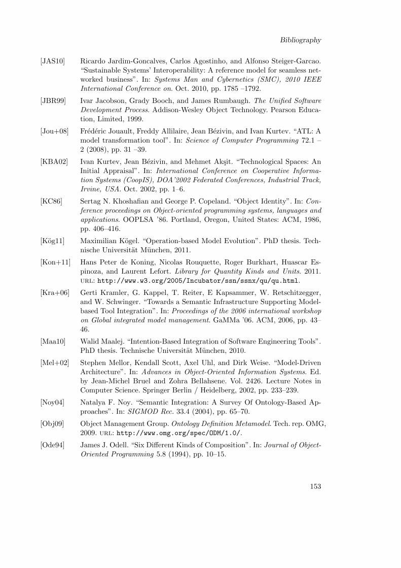
Bibliography
[JAS10] Ricardo Jardim-Goncalves, Carlos Agostinho, and Alfonso Steiger-Garcao.“Sustainable Systems’ Interoperability: A reference model for seamless net-worked business”. In: Systems Man and Cybernetics (SMC), 2010 IEEEInternational Conference on. Oct. 2010, pp. 1785 –1792.
[JBR99] Ivar Jacobson, Grady Booch, and James Rumbaugh. The Unified SoftwareDevelopment Process. Addison-Wesley Object Technology. Pearson Educa-tion, Limited, 1999.
[Jou+08] Frederic Jouault, Freddy Allilaire, Jean Bezivin, and Ivan Kurtev. “ATL: Amodel transformation tool”. In: Science of Computer Programming 72.1 –2 (2008), pp. 31 –39.
[KBA02] Ivan Kurtev, Jean Bezivin, and Mehmet Aksit. “Technological Spaces: AnInitial Appraisal”. In: International Conference on Cooperative Informa-tion Systems (CoopIS), DOA’2002 Federated Conferences, Industrial Track,Irvine, USA. Oct. 2002, pp. 1–6.
[KC86] Sertag N. Khoshafian and George P. Copeland. “Object Identity”. In: Con-ference proceedings on Object-oriented programming systems, languages andapplications. OOPLSA ’86. Portland, Oregon, United States: ACM, 1986,pp. 406–416.
[Kog11] Maximilian Kogel. “Operation-based Model Evolution”. PhD thesis. Tech-nische Universitat Munchen, 2011.
[Kon+11] Hans Peter de Koning, Nicolas Rouquette, Roger Burkhart, Huascar Es-pinoza, and Laurent Lefort. Library for Quantity Kinds and Units. 2011.url: http://www.w3.org/2005/Incubator/ssn/ssnx/qu/qu.html.
[Kra+06] Gerti Kramler, G. Kappel, T. Reiter, E Kapsammer, W. Retschitzegger,and W. Schwinger. “Towards a Semantic Infrastructure Supporting Model-based Tool Integration”. In: Proceedings of the 2006 international workshopon Global integrated model management. GaMMa ’06. ACM, 2006, pp. 43–46.
[Maa10] Walid Maalej. “Intention-Based Integration of Software Engineering Tools”.PhD thesis. Technische Universitat Munchen, 2010.
[Mel+02] Stephen Mellor, Kendall Scott, Axel Uhl, and Dirk Weise. “Model-DrivenArchitecture”. In: Advances in Object-Oriented Information Systems. Ed.by Jean-Michel Bruel and Zohra Bellahsene. Vol. 2426. Lecture Notes inComputer Science. Springer Berlin / Heidelberg, 2002, pp. 233–239.
[Noy04] Natalya F. Noy. “Semantic Integration: A Survey Of Ontology-Based Ap-proaches”. In: SIGMOD Rec. 33.4 (2004), pp. 65–70.
[Obj09] Object Management Group. Ontology Definition Metamodel. Tech. rep. OMG,2009. url: http://www.omg.org/spec/ODM/1.0/.
[Ode94] James J. Odell. “Six Different Kinds of Composition”. In: Journal of Object-Oriented Programming 5.8 (1994), pp. 10–15.
153
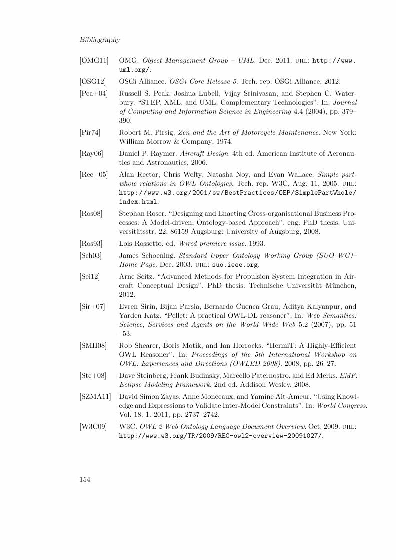
Bibliography
[OMG11] OMG. Object Management Group – UML. Dec. 2011. url: http://www.uml.org/.
[OSG12] OSGi Alliance. OSGi Core Release 5. Tech. rep. OSGi Alliance, 2012.
[Pea+04] Russell S. Peak, Joshua Lubell, Vijay Srinivasan, and Stephen C. Water-bury. “STEP, XML, and UML: Complementary Technologies”. In: Journalof Computing and Information Science in Engineering 4.4 (2004), pp. 379–390.
[Pir74] Robert M. Pirsig. Zen and the Art of Motorcycle Maintenance. New York:William Morrow & Company, 1974.
[Ray06] Daniel P. Raymer. Aircraft Design. 4th ed. American Institute of Aeronau-tics and Astronautics, 2006.
[Rec+05] Alan Rector, Chris Welty, Natasha Noy, and Evan Wallace. Simple part-whole relations in OWL Ontologies. Tech. rep. W3C, Aug. 11, 2005. url:http://www.w3.org/2001/sw/BestPractices/OEP/SimplePartWhole/
index.html.
[Ros08] Stephan Roser. “Designing and Enacting Cross-organisational Business Pro-cesses: A Model-driven, Ontology-based Approach”. eng. PhD thesis. Uni-versitatsstr. 22, 86159 Augsburg: University of Augsburg, 2008.
[Ros93] Lois Rossetto, ed. Wired premiere issue. 1993.
[Sch03] James Schoening. Standard Upper Ontology Working Group (SUO WG)–Home Page. Dec. 2003. url: suo.ieee.org.
[Sei12] Arne Seitz. “Advanced Methods for Propulsion System Integration in Air-craft Conceptual Design”. PhD thesis. Technische Universitat Munchen,2012.
[Sir+07] Evren Sirin, Bijan Parsia, Bernardo Cuenca Grau, Aditya Kalyanpur, andYarden Katz. “Pellet: A practical OWL-DL reasoner”. In: Web Semantics:Science, Services and Agents on the World Wide Web 5.2 (2007), pp. 51–53.
[SMH08] Rob Shearer, Boris Motik, and Ian Horrocks. “HermiT: A Highly-EfficientOWL Reasoner”. In: Proceedings of the 5th International Workshop onOWL: Experiences and Directions (OWLED 2008). 2008, pp. 26–27.
[Ste+08] Dave Steinberg, Frank Budinsky, Marcello Paternostro, and Ed Merks. EMF:Eclipse Modeling Framework. 2nd ed. Addison Wesley, 2008.
[SZMA11] David Simon Zayas, Anne Monceaux, and Yamine Ait-Ameur. “Using Knowl-edge and Expressions to Validate Inter-Model Constraints”. In: World Congress.Vol. 18. 1. 2011, pp. 2737–2742.
[W3C09] W3C. OWL 2 Web Ontology Language Document Overview. Oct. 2009. url:http://www.w3.org/TR/2009/REC-owl2-overview-20091027/.
154

Bibliography
[WCH87] Morton E. Winston, Roger Chaffin, and Douglas Herrmann. “A Taxonomyof Part-Whole Relations”. In: Cognitive Science 11.4 (1987), pp. 417 –444.
[Woh+00] Claes Wohlin, Per Runeson, Martin Host, Magnus C. Ohlsson, Bjorn Reg-nell, and Anders Wesselen. Experimentation in Software Engineering. Vol. 6.Springer, 2000.
[ZGS11] Sven Ziemer, Martin Glas, and Gernot Stenz. “A Conceptual Design Tool forMulti-Disciplinary Aircraft Design”. In: Aerospace Conference, 2011 IEEE.Mar. 2011, pp. 1–13.
155