op 456 3 english.book page -1 thursday, may 24, 2007 9…-02... · op_456_3_english.book page 1...
TRANSCRIPT

Eng
lish
ge
s
Op_456_3_English.book Page -1 Thursday, May 24, 2007 9:46 PM
Elcometer 4563
Coating Thickness Gau
Basic Models
Operating Instruction

Eng
lish
models:
Equipmen g Patents:FNF UK Pa 86522F1 2 UK Pa 6,762,603F1 2 Germa
This 93/68/EEC.
All other tra
© CopyrightAll rights res ibed, stored (in a retrieval system orotherwise) o echanical, magnetic, optical, manualor otherwiseA copy of th lcometer.com/downloads.
Doc.No. TMA-0422 Issue 02Text with Cover No: 20241
Op_456_3_English.book Page 0 Thursday, May 24, 2007 9:46 PM
R
These instructions apply to the following Elcometer 4563
Ferrous (F), Non-Ferrous (NF) and Dual Ferrous/Non-Ferrous (FNF)
t described in these instructions is covered by the followintent No: GB2306009B FNF US Patent No: 58tent No: 2367135B F1 2 US Patent No. USn Patent Pending
product meets the emc directive 89/336/EEC, amended 92/31/EEC and
and are registered trademarks of Elcometer Instruments Ltd.
demarks acknowledged.
Elcometer Instruments Ltd. 2004-2007.erved. No part of this Document may be reproduced, transmitted, transcrr translated into any language, in any form or by any means (electronic, m) without the prior written permission of Elcometer Instruments Ltd.is Instruction Manual is available for download on our Website via www.e
R
1
Page. . . . . . . . . . . . . . . . . . . . . . . . 4. . . . . . . . . . . . . . . . . . . . . . . . 5. . . . . . . . . . . . . . . . . . . . . . . . 5. . . . . . . . . . . . . . . . . . . . . . . . 6. . . . . . . . . . . . . . . . . . . . . . . . 6. . . . . . . . . . . . . . . . . . . . . . . . 6. . . . . . . . . . . . . . . . . . . . . . . . 7. . . . . . . . . . . . . . . . . . . . . . . . 7. . . . . . . . . . . . . . . . . . . . . . . . 7. . . . . . . . . . . . . . . . . . . . . . . . 8. . . . . . . . . . . . . . . . . . . . . . . . 9. . . . . . . . . . . . . . . . . . . . . . . . 9. . . . . . . . . . . . . . . . . . . . . . . 10. . . . . . . . . . . . . . . . . . . . . . . 10. . . . . . . . . . . . . . . . . . . . . . . 11. . . . . . . . . . . . . . . . . . . . . . . 12. . . . . . . . . . . . . . . . . . . . . . . 12. . . . . . . . . . . . . . . . . . . . . . . 12. . . . . . . . . . . . . . . . . . . . . . . 13
Op_456_3_English.book Page 1 Thursday, May 24, 2007 9:46 PM
CONTENTS
Section1 About your gauge . . . . . . . . . . . . . . . . . . . . . . . . . . . . . . . . . . . . . . . 1.1 Features . . . . . . . . . . . . . . . . . . . . . . . . . . . . . . . . . . . . . . . . . . . . . . . . 1.2 Standards . . . . . . . . . . . . . . . . . . . . . . . . . . . . . . . . . . . . . . . . . . . . . . . 1.3 What this box contains . . . . . . . . . . . . . . . . . . . . . . . . . . . . . . . . . . . . . 1.4 Conventions in these instructions . . . . . . . . . . . . . . . . . . . . . . . . . . . . 1.5 Quick-start . . . . . . . . . . . . . . . . . . . . . . . . . . . . . . . . . . . . . . . . . . . . . . 2 Getting started . . . . . . . . . . . . . . . . . . . . . . . . . . . . . . . . . . . . . . . . . . 2.1 Fitting the batteries . . . . . . . . . . . . . . . . . . . . . . . . . . . . . . . . . . . . . . . 2.2 Battery condition. . . . . . . . . . . . . . . . . . . . . . . . . . . . . . . . . . . . . . . . . . 2.3 Fitting probes . . . . . . . . . . . . . . . . . . . . . . . . . . . . . . . . . . . . . . . . . . . . 2.4 The controls . . . . . . . . . . . . . . . . . . . . . . . . . . . . . . . . . . . . . . . . . . . . . 2.5 Switching the gauge on . . . . . . . . . . . . . . . . . . . . . . . . . . . . . . . . . . . . 2.6 Switching the gauge off . . . . . . . . . . . . . . . . . . . . . . . . . . . . . . . . . . . . 2.7 The screen . . . . . . . . . . . . . . . . . . . . . . . . . . . . . . . . . . . . . . . . . . . . . . 2.8 Selecting a language . . . . . . . . . . . . . . . . . . . . . . . . . . . . . . . . . . . . . . 2.9 Interfaces . . . . . . . . . . . . . . . . . . . . . . . . . . . . . . . . . . . . . . . . . . . . . . . 3 Taking a reading . . . . . . . . . . . . . . . . . . . . . . . . . . . . . . . . . . . . . . . . 3.1 Before you start . . . . . . . . . . . . . . . . . . . . . . . . . . . . . . . . . . . . . . . . . . 3.2 Procedure . . . . . . . . . . . . . . . . . . . . . . . . . . . . . . . . . . . . . . . . . . . . . .

. . . . . . . . . . . . . . . . . . . . . . . 13
. . . . . . . . . . . . . . . . . . . . . . . 13
. . . . . . . . . . . . . . . . . . . . . . . 14
. . . . . . . . . . . . . . . . . . . . . . . 15
. . . . . . . . . . . . . . . . . . . . . . . 18
. . . . . . . . . . . . . . . . . . . . . . . 22
. . . . . . . . . . . . . . . . . . . . . . . 22
. . . . . . . . . . . . . . . . . . . . . . . 23
. . . . . . . . . . . . . . . . . . . . . . . 24
. . . . . . . . . . . . . . . . . . . . . . . 29
. . . . . . . . . . . . . . . . . . . . . . . 30
. . . . . . . . . . . . . . . . . . . . . . . 30
. . . . . . . . . . . . . . . . . . . . . . . 30
. . . . . . . . . . . . . . . . . . . . . . . 31
. . . . . . . . . . . . . . . . . . . . . . . 31
Op_456_3_English.book Page 2 Thursday, May 24, 2007 9:46 PM
R
2
4 The reading screen and menus . . . . . . . . . . . . . . . . . . . . . . . . . . . . 4.1 Reading screen . . . . . . . . . . . . . . . . . . . . . . . . . . . . . . . . . . . . . . . . . . 4.2 Main MENU . . . . . . . . . . . . . . . . . . . . . . . . . . . . . . . . . . . . . . . . . . . . . 4.3 Main MENU - Extended menu off . . . . . . . . . . . . . . . . . . . . . . . . . . . . 4.4 Main MENU - Extended menu on . . . . . . . . . . . . . . . . . . . . . . . . . . . . 5 Calibration adjustment . . . . . . . . . . . . . . . . . . . . . . . . . . . . . . . . . . . 5.1 Calibration method . . . . . . . . . . . . . . . . . . . . . . . . . . . . . . . . . . . . . . . . 5.2 Calibration foils and standards . . . . . . . . . . . . . . . . . . . . . . . . . . . . . . . 5.3 Calibration adjustment procedure . . . . . . . . . . . . . . . . . . . . . . . . . . . . 6 Statistics . . . . . . . . . . . . . . . . . . . . . . . . . . . . . . . . . . . . . . . . . . . . . . . 6.1 Enlarge stats . . . . . . . . . . . . . . . . . . . . . . . . . . . . . . . . . . . . . . . . . . . . 6.2 Stats on LCD . . . . . . . . . . . . . . . . . . . . . . . . . . . . . . . . . . . . . . . . . . . . 6.3 Display . . . . . . . . . . . . . . . . . . . . . . . . . . . . . . . . . . . . . . . . . . . . . . . . . 6.4 Clear stats . . . . . . . . . . . . . . . . . . . . . . . . . . . . . . . . . . . . . . . . . . . . . . 6.5 Select stats . . . . . . . . . . . . . . . . . . . . . . . . . . . . . . . . . . . . . . . . . . . . .

R
3
. . . . . . . . . . . . . . . . . . . . . . . 31
. . . . . . . . . . . . . . . . . . . . . . . 34
. . . . . . . . . . . . . . . . . . . . . . . 35
. . . . . . . . . . . . . . . . . . . . . . . 35
. . . . . . . . . . . . . . . . . . . . . . . 36
. . . . . . . . . . . . . . . . . . . . . . . 37
. . . . . . . . . . . . . . . . . . . . . . . 38
. . . . . . . . . . . . . . . . . . . . . . . 40
. . . . . . . . . . . . . . . . . . . . . . . 41
. . . . . . . . . . . . . . . . . . . . . . . 42
. . . . . . . . . . . . . . . . . . . . . . . 43
. . . . . . . . . . . . . . . . . . . . . . . 50
. . . . . . . . . . . . . . . . . . . . . . . 52
Op_456_3_English.book Page 3 Thursday, May 24, 2007 9:46 PM
7 Probes . . . . . . . . . . . . . . . . . . . . . . . . . . . . . . . . . . . . . . . . . . . . . . . . . 8 Personalised welcome screen . . . . . . . . . . . . . . . . . . . . . . . . . . . . . 9 Storage and transit . . . . . . . . . . . . . . . . . . . . . . . . . . . . . . . . . . . . . . 10 Maintenance . . . . . . . . . . . . . . . . . . . . . . . . . . . . . . . . . . . . . . . . . . . . 11 Statistics terminology . . . . . . . . . . . . . . . . . . . . . . . . . . . . . . . . . . . . 12 Technical data . . . . . . . . . . . . . . . . . . . . . . . . . . . . . . . . . . . . . . . . . . 13 Accessories . . . . . . . . . . . . . . . . . . . . . . . . . . . . . . . . . . . . . . . . . . . . 14 Related equipment . . . . . . . . . . . . . . . . . . . . . . . . . . . . . . . . . . . . . . . 15 Fitting the wrist harness . . . . . . . . . . . . . . . . . . . . . . . . . . . . . . . . . . 16 Probe measurement performance . . . . . . . . . . . . . . . . . . . . . . . . . . 17 Probe capabilities . . . . . . . . . . . . . . . . . . . . . . . . . . . . . . . . . . . . . . . 18 Error messages . . . . . . . . . . . . . . . . . . . . . . . . . . . . . . . . . . . . . . . . .
19 Index . . . . . . . . . . . . . . . . . . . . . . . . . . . . . . . . . . . . . . . . . . . . . . . . . .

able inBasic,. This
s thethe
sic. gauge-to-useaphicales the
s suchurationbration
ble either with a built-in integralate probe version. A wide rangeble to suit requirements - see probes may be standard, Integral Probes (PINIP™), andparately.
R
Figure 1. Elcometer 4563
Coating Thickness Gauge
Op_456_3_English.book Page 4 Thursday, May 24, 2007 9:46 PM
R
4
Thank you for your purchase of this Elcometer 4563
Coating Thickness Gauge. Welcome to Elcometer.Elcometer are world leaders in the design,manufacture and supply of coatings inspectionequipment. Our products cover all aspects ofcoating inspection, from development throughapplication to post application inspection.The Elcometer 4563 Coating Thickness Gauge is aworld beating product. With the purchase of thisgauge you now have access to the worldwideservice and support network of Elcometer. Formore information visit our website atwww.elcometer.com.
1 ABOUT YOUR GAUGE
The Elcometer 4563 Coating Thickness Gauge is ahandheld gauge for fast and accuratemeasurement of the thickness of coatings on metalsubstrates.
The gauge is availthree versions; Standard and Topmanual describeoperation of Elcometer 4563 BaAll versions of thefeature an easymenu driven grinterface which guiduser through taskas gauge configand caliadjustment.
The gauge is availaprobe or as a separof probes is availapage 31. Separateminiature or Plug inmust be ordered se
R
5
can be used in accordance withal and International Standards:
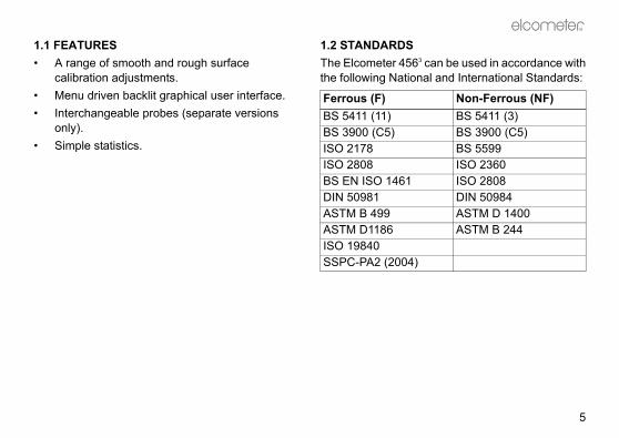
Non-Ferrous (NF)BS 5411 (3)BS 3900 (C5) BS 5599ISO 2360ISO 2808DIN 50984ASTM D 1400ASTM B 244
Op_456_3_English.book Page 5 Thursday, May 24, 2007 9:46 PM
1.1 FEATURES• A range of smooth and rough surface
calibration adjustments.• Menu driven backlit graphical user interface.• Interchangeable probes (separate versions
only).• Simple statistics.
1.2 STANDARDSThe Elcometer 4563
the following Nation
Ferrous (F)BS 5411 (11)BS 3900 (C5)ISO 2178ISO 2808BS EN ISO 1461DIN 50981ASTM B 499ASTM D1186ISO 19840SSPC-PA2 (2004)

re the gauge and start taking
see page 7see page 8see page 9
e: see page 11ding: see page 12n: see page 22onfigured and ready to use.e benefits of your newease take some time to readstructions. Do not hesitate to or your Elcometer supplier ifstions.
parate probes only
Op_456_3_English.book Page 6 Thursday, May 24, 2007 9:46 PM
R
6
1.3 WHAT THIS BOX CONTAINS• Elcometer 4563 Gauge with integral probe, or
Elcometer 4563 Gauge and separate probe(probe must be ordered separately)
• Calibration foils• Gauge carrying pouch• Wrist harness• Batteries• Operating instructions
1.4 CONVENTIONS IN THESE INSTRUCTIONSThe Elcometer 4563 is controlled using a simplemenu structure which helps you get the most fromyour gauge - see page 18.As an example, the LANGUAGES option which is inSETUP from the MAIN MENU would be shown inthese instructions asMENU/SETUP/LANGUAGES.These instructions include images of Elcometer4563 screens with units set to microns (µm). Similarscreens will be seen when the gauge is set to otherunits such as mils or inches.
1.5 QUICK-STARTTo quickly configureadings:1. Fit batteries:2. Fit probea:3. Switch on:4. Select languag5. Try taking a rea6. Adjust calibratioThe gauge is now cTo maximise thElcometer 4563, plthese Operating Incontact Elcometeryou have any que
a. Gauges with se

R
7
DITION.
condition/action required
00%
6%, replacement ended.
3%, replacement required.
auge beeps every 10 seconds bol flashes - immediate ent required.
eeps, gauge switches off ically.
Op_456_3_English.book Page 7 Thursday, May 24, 2007 9:46 PM
2 GETTING STARTED
2.1 FITTING THE BATTERIES1. Open battery compartment cover; press down
in direction of arrow using thumb nail.2. Insert 2 x LR03 (AAA), alkaline dry batteries
taking care to ensure correct battery polarity(Figure 2).
3. Close battery compartment cover.Rechargeable batteries can be used but they willonly have 25% to 30% of the life of alkalinebatteries.
Figure 2. Fitting batteries -ensure correct battery polarity
2.2 BATTERY CON
Symbol Battery
100%
66% to 1
33% to 6recomm
16% to 3
<16%, gand symreplacem5 loud bautomat

betion and pulle gauge. Thelock and the
ntil theTakings theobe byg ringse, or
Op_456_3_English.book Page 8 Thursday, May 24, 2007 9:46 PM
R
8
2.3 FITTING PROBES(separate versions only)
To ensure correct transfer of data from theprobe and detection of the new probe, thegauge must be switched off when
separate probes are fitted.A probe must be calibrated once it has beenfitted - see “Calibration adjustment” on page 22.
To fit the probeAlign connector keyway andpush in direction shown. Theconnector locks automatically.Note: The design of the probeconnector allows somemovement between the probeand the gauge. This is intentionaland does not affectmeasurement performance.
To release the proGrasp knurled secgently away from thconnection will unprobe will release.
To fit the PINIP™Twist the PINIP™ uconnector locates. care not to crosthreads, lock the prturning the lockin1½ times clockwiuntil tight.

R
9
E GAUGE ON
hing the gauge on for the first a language” on page 11.
e
to
toor a
R
R
CAL DATA STATS MENU
09 : 30 09 / 10 / 2000F1
F456
Op_456_3_English.book Page 9 Thursday, May 24, 2007 9:46 PM
2.4 THE CONTROLSThe gauge is operated by 5 keys (Figure 3).
• On/Off key : Switches the gauge on or off.• Softkeys: The function of these keys varies
and is described by symbols and writing on thebottom line of the screen.
• LED: Red/green flashes when the gauge isswitched on, green flashes when a reading istaken.
Figure 3. Elcometer 4563 control keys
2.5 SWITCHING TH
Note: Before switctime read “Selecting
R
Softkeys
On/Off key
LED
Gauges with separatand PINIP™ probes:Press key switch on gauge.
Gauges with integralprobes:Press key switch on gauge, place the probe onsurface.

is switched on a welcomemay be displayed briefly (Figure
al Elcometer 4563 welcome screen
e measurement values andlayed is called the Readingcter size of the measurement additional information is shownure 5). To maximise charactertatistics (see Stats on LCD,k the softkeys (see SOFTKEYS).
al Elcometer 4563 reading screens
Op_456_3_English.book Page 10 Thursday, May 24, 2007 9:46 PM
R
10
2.6 SWITCHING THE GAUGE OFFTo switch off all gaugetypes, press and hold
key for 3 seconds.The gauge will beep,two single tonesfollowed by a doubletone.The Elcometer 4563 switches itself off 60 secondsafter the last operation unless the Auto Switch Offtime is changed (MENU/SETUP/AUTO SWITCHOFF). The Auto Switch Off feature can be set to amaximum of 10 minutes or can be deactivated - see“AUTO SWITCH OFF:” on page 20.
2.7 THE SCREENFamiliarise yourself with the Elcometer 4563 screen.The screen displays:• Welcome information• Measurement information• Menus to configure the gauge and control
functions• Help and miscellaneous information
When the gauge information screen 4).
Figure 4. Typic
The screen wherstatistics are dispScreen. The charavalue decreases ason the display (Figsize, switch off spage 30) and unlocLOCKED:, page 21
Figure 5. Typic
R
3 seconds

R
11
ff. left hand softkey.o switch on gauge.ill show language selectionrrent language highlighted by
nd softkey.ructions given above to select
t MENU/SETUP/LANGUAGESU - Extended menu on” on
Op_456_3_English.book Page 11 Thursday, May 24, 2007 9:46 PM
2.8 SELECTING A LANGUAGEThe Elcometer 4563 has over 20 built-in languages.When the gauge is switched on for the first timeafter dispatch from the Elcometer factory thedisplay will show the language selection screen(Figure 6).
Figure 6. Language selection screen
AT FIRST SWITCH ON1. Press Up/Down softkeys to locate language
required.2. Press SEL softkey to activate the selected
language.The screen displays an Elcometer 4563
welcome screen (Figure 4) followed by thereading screen (Figure 5).The gauge operates in the new language untilchanged.
AT ANY TIME1. Switch gauge o2. Press and hold3. Press key t
The display wscreen with cucursor.
4. Release left haFollow the instthe language.
Alternatively, selec- see “Main MENpage 18.
DING
STARThe correct type of probe?n page 31.librated?n adjustment” on page 22.statistics? on page 29.measurement do you want to
n page 20.
Op_456_3_English.book Page 12 Thursday, May 24, 2007 9:46 PM
R
12
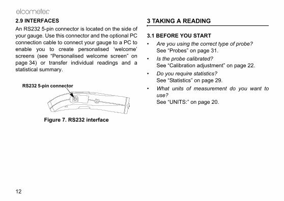
2.9 INTERFACESAn RS232 5-pin connector is located on the side ofyour gauge. Use this connector and the optional PCconnection cable to connect your gauge to a PC toenable you to create personalised ‘welcome’screens (see “Personalised welcome screen” onpage 34) or transfer individual readings and astatistical summary.
Figure 7. RS232 interface
3 TAKING A REA
3.1 BEFORE YOU • Are you using t
See “Probes” o• Is the probe ca
See “Calibratio• Do you require
See “Statistics”• What units of
use?See “UNITS:” o
RS232 5-pin connector

R
13
SCREEN AND MENUS
EENe reading screen (Figure 10, upon the type of measurementw the gauge is set up.
ple of reading screen with calibration method selected
lected calibration adjustment
the main MENU of the gauges to user-selectable features -
ing
)Battery state
Substrate
Unitstions/symbols
Calibration Method
Op_456_3_English.book Page 13 Thursday, May 24, 2007 9:46 PM
3.2 PROCEDURE1. Press key to switch on gauge.2. Place probe on surface to be measured. The
reading may be inaccurate if the probe isnot held as shown in Figure 8.
Figure 8. Taking a reading
3. Reading is displayed on screen (Figure 9).
Figure 9. Typical reading
4 THE READING
4.1 READING SCRThe content of thFigure 11) dependsbeing made and ho
Figure 10. Examsmooth surface
CAL: Operates semethod.MENU: This opensand provides accessee page 18.
R
Separate probe Integral probe
R
CAL DATA STATS MENU
09 : 30 09 / 10 / 2000F1
F456Automatic-switchprobe symbol(FNF probes only
Softkey func

n and measurement functionsing menus (Figure 12). Theus is shown on page 18.
ical Elcometer 4563 menu
w the status of a feature to be off or select or deselect, etc. Aes this type of feature. A ticktem indicates the function isd.ts the option displayed and in the status of a tick box off/on.h i move the cursor to the menu
enus scroll up/down and a linedicates the start and end of the
Menu title
Menu contents
Softkey functions
Op_456_3_English.book Page 14 Thursday, May 24, 2007 9:46 PM
R
14
Note: If CAL softkey symbol is flashing the gaugeshould be recalibrated. This is due to the calibrationadjustment method having been changed or aprobe change - see “Calibration adjustment” onpage 22.
Figure 11. Reading screen in extended mode and showing full set of statistical values.
4.2 MAIN MENUGauge configuratioare controlled usstructure of the men
Figure 12. Typ
Some screens allochanged e.g. on totick box indicatagainst a menu iactivated or selecteSEL softkey selecsome cases togglesUp/Down softkeys item required. The macross the screen inmenu.

R
15
XTENDED MENU OFF
menu - extended menu off
on and off. Toggle tick box to With BACKLIGHT activatedminated for approximately 5
ading is taken or a key pressed.fe is reduced by about one third is activated.
KEDdvertent calibration adjustment.o activate/deactivate. If CALwhile CALIBRATION LOCKEDauge displays CALIBRATIONU TO UNLOCK. The messageeconds.
Op_456_3_English.book Page 15 Thursday, May 24, 2007 9:46 PM
BACK softkey returns the gauge to a previousscreen. Holding this softkey down will rapidly exitfrom any menu and return to the reading screen.
SIMPLE AND EXTENDED MENUSThe Elcometer 4563 Basic Gauge has two menustructures:• Extended menu off (simple menu mode):
The gauge is shipped from the Elcometerfactory with EXTENDED MENU turned off. Inthis simple menu mode the gauge can becalibrated and used to take measurements.This is the ideal setting for users who do notrequire access to advanced features of thegauge.
• Extended menu on (extended menu mode):Additional items are automatically added to theMENU and the STATS softkey is activated.These give access to more advanced functionssuch as statistics, calibration method,print/output, setup, etc.
4.3 MAIN MENU - E
Figure 13. Main
BACKLIGHTSwitches backlightactivate/deactivate.the display is illuseconds when a reNote: The battery liwhen the backlight
CALIBATION LOCProtects against inaToggle tick box tsoftkey is pressed is activated the gLOCKED USE MENdisappears after 3 s

libration or Gauge resets. Then (Figure 15) allows one of threeselected:eturns gauge to calibrationt time of manufacture of the
will not necessarily restorevalues. The calibration of thedjusted before use, or at least that it has been previously
or the conditions of use.
sets gauge to International. DD/MM/YY date format and
ngs can also be activated at switchld softkey 3 and switch on gauge.
Op_456_3_English.book Page 16 Thursday, May 24, 2007 9:46 PM
R
16
EXTENDED MENUProvides access to additional features. Toggle tickbox to activate/deactivate. See “Main MENU -Extended menu on” on page 18.
ABOUTProvides information on Gauge, Probe, Contactinformation and Help (Figure 14):GAUGE INFORMATION: Elcometer 4563 model,software versions, etc.PROBE INFORMATION: Probe type, range, etc.CONTACT: Details of Elcometer offices worldwideand, if programmed, the contact details for theSupplier or Local Distributor.HELP: Explains symbols used on Elcometer 4563
display screens.
Figure 14. About menu
RESETSelects Factory CaRESET menu optiogauge resets to be FACTORY CAL: Rsettings created aprobe.Factory calibrationprecise calibration gauge should be achecked to ensureadjusted correctly f
INTL GAUGEb: Redefault settings e.gmetric units.
b. International settion. Press and ho
R
17
Op_456_3_English.book Page 17 Thursday, May 24, 2007 9:46 PM
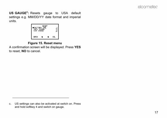
US GAUGEC: Resets gauge to USA defaultsettings e.g. MM/DD/YY date format and imperialunits.
Figure 15. Reset menuA confirmation screen will be displayed. Press YESto reset, NO to cancel.
c. US settings can also be activated at switch on. Pressand hold softkey 4 and switch on gauge.

SELECT STATSNO. OF READINGSMEANSTD DEVIATIONCOEF OF VARIAT’NHIGHEST READINGLOWEST READING
BAUD RATE12002400480096001440019200
Op_456_3_English.book Page 18 Thursday, May 24, 2007 9:46 PM
R
18
4.4 MAIN MENU - EXTENDED MENU ONTo toggle EXTENDED MENU on/off select MENU/EXTENDED MENU/SEL
STATSENLARGE STATSSTATS ON LCDDISPLAY F1CLEAR STATSSELECT STATS
CALPROBE CALIBRATION
MENUBACKLIGHTCALIBRATION LOCKEDEXTENDED MENUPRINT/OUTPUTDELETECAL METHODSETUPABOUTRESET
CAL METHODSMOOTH2 POINTROUGHSPECIAL SUBZERO OFFSETSET OFFSET
DELETELAST READING
SETUPSTATISTICSPROBEUNITSAUTO SWITCH OFF 1OUTPUTBEEP VOLUME 3LANGUAGESLARGE FONTSSOFTKEYS LOCKEDOPENING SCREEN
ABOUTGAUGE INFORMATIONPROBE INFORMATIONCONTACTHELP
RESETFACTORY CALINTL GAUGEUS GAUGE
PRINT/OUTPUTCURRENT STATISTICS
STATISTICSSOFTKEY ENABLEDSELECT STATSDISPLAY F1
OUTPUTBAUD RATERS232 BIT IMAGERS232 PLAIN TEXT

R
19
g to delete, the gauge displays:
e last reading not available screen
to Delete menu.
calibration method from list ofration method” on page 22 for
nge or activate gauge features:ates simple statistics feature..elect stats” on page 31.
lay” on page 30.ual function probes (FNF and F1mode.
Op_456_3_English.book Page 19 Thursday, May 24, 2007 9:46 PM
The following features are added to the MENUwhen EXTENDED MENU is active:
PRINT/OUTPUTOutputs individual readings or a statistical summaryvia the RS232 interface.To use this function, first setup using:MENU/SETUP/OUTPUT - see “OUTPUT:” onpage 20.
DELETEDeletes last reading only. Gauge displays AREYOU SURE? (Figure 16).
Figure 16. Delete last reading confirmation screen
Press NO softkey to include reading in statisticalsummary or YES softkey to delete reading.
If there is no readin
Figure 17. Delet
Press OK to return
CAL METHODAllows selection ofoptions - see “Calibmore details.
SETUPUsed to select, chaSTATISTICS: ActivStats softkey on/offSelect stats - see “SDisplay - see “DispPROBE: Only for d2). Changes probe

baud rate (Figure 18) andut via the RS232 interface - seee 12.
8. OUTPUT screen
be set at values from 1200 tovalue is 9600 baud.GE Toggle tick box to
When activated, readings areinterface as they are taken. Allters are output as bit-maps. Thisthe Elcometer Miniprinter (seee 39).
Op_456_3_English.book Page 20 Thursday, May 24, 2007 9:46 PM
R
20
FNF probes - select from Automatic, F or N.F1 2 probes - select from F1 or F2.UNITS: Units are automatically set by the probetype, however the user can manually override theautomatic setting. Select from µm, mm, mil, thou orinch.AUTO SWITCH OFF: Changes delay beforegauge switches off when displaying ReadingScreen.• Minimum = 1 minute• Maximum = 10 minutes• Default = 1 minuteAuto switch off may be disabled by selecting ‘off’ (Inthis case, switch off using On/Off key .)OUTPUT: Activates data output. Toggle tick box toactivate/deactivate. When activated, readings aresent to the mini portable printer as they are taken.See “Miniprinter” on page 39 for sales part numberof this optional accessory.
OUTPUT: Selects activates data outp“Interfaces” on pag
Figure 1
BAUD RATE can 19200. The default RS232 BIT IMAactivate/deactivate.sent to the RS232 images and characallows printing on “Miniprinter” on pag

R
21
hen ticked, displays all menusouble height, single width fonts
lity, if needed).
. Large fonts enabled
ED: When ticked, the softkeys be displayed.
ftkeys locked/unlocked
e softkey functions disappearreen 5 seconds after the readingdisplayed, or 5 seconds after To view the functions again,e four softkeys.re always visible in menus.
Op_456_3_English.book Page 21 Thursday, May 24, 2007 9:46 PM
RS232 PLAIN TEXT Toggle tick box toactivate/deactivate. When activated, readings aresent to the RS232 interface as they are taken. Thegauge sends standard ASCII characters from theCourier New font setd. This allows printing ondevices other than the Elcometer Miniprinter, e.g.RS 232 printers or PC via Elcometer software or viaHyperTerminal.BEEP VOLUME: Changes volume.• 0 = off• 5 = loudest• Default = 3LANGUAGES: Allows selection of language.If a personalised welcome screen has beendownloaded into the gauge (see page 34), OpeningScreen must be activated to display this screen.
LARGE FONTS: Wand screens using d(for improved legibi
Figure 19
SOFTKEYS LOCKfunctions will alway
Figure 20. So
When un-ticked, thfrom the reading scscreen has been pressing any key.press any one of thSoftkey functions a
d. When RS232 Plain Text is selected the following lan-guages will be output as English: Chinese, Greek,Hebrew, Japanese, Korean, Russian, Lithuanian,Farsi.

indicated on the screen by a
CAL METHOD screen
surface calibration where the on the uncoated surface and a
bove the expected thickness of
n on a thin value and a thickf the expected thickness. Thisuracy of the gauge over thefined by the two values.tion method similar to 2-Point.accuracy of the gauge over thefined by the two values.is method uses the 2-Pointual substrate materials such astypes of stainless steel, highl aluminium alloys, etc.
Op_456_3_English.book Page 22 Thursday, May 24, 2007 9:46 PM
R
22
OPENING SCREEN: Disables the opening(welcome) screens so that the gauge switches on todisplay the reading screen.
5 CALIBRATION ADJUSTMENT
Calibration adjustment is the process of setting thegauge to known values of thickness to ensureaccuracy on different substrate types, shapes andsurface finishes.Note: When using an FNF probe it must becalibrated in both the ferrous mode and in the non-ferrous mode to ensure accuracy of reading.
5.1 CALIBRATION METHODThe calibration of the gauge can be adjusted(MENU/CAL METHOD) using several differentmethods described in National and InternationalStandards.The calibration adjustment method chosen isdependant on the condition of the substrate to be
measured and is symbol (Figure 21):
Figure 21.
SMOOTH: Smoothgauge is set to zeroknown thickness athe coating.2POINT: Calibratiovalue either side oenhances the accthickness range deROUGH: A calibraThis enhances the thickness range deSPECIAL SUB: Thcalibration for unuscast iron, certain carbon steel, specia

R
23
ibration method is changed, e.g.ough, the gauge will display a).
alibration required screen
is pressed the CAL softkeydings Screen will flash to warnstment is still required.y is pressed the calibrationre is activated - see “Calibrationre” on page 24.
FOILS AND STANDARDSent should be carried out withbe on the same type of metal, and similar finish to the item toest to use an uncoated samplested.arried out using measured foils.
Op_456_3_English.book Page 23 Thursday, May 24, 2007 9:46 PM
ZERO OFFSET: This is the method described inISO 19840 for coatings on steel surfacesroughened by blast cleaning. The calibration usesthe smooth surface technique, and a correctionvalue (zero offset) is applied to each reading toaccount for the effect of the roughened surface; thevalue depends on the surface profile - see Table 1.SET OFFSET: This screen sets and changes theoffset for different surface roughness This value isused only with the Zero Offset calibration method.
Note: When the calfrom Smooth to Rmessage (Figure 22
Figure 22. Rec
If the NO softkeysymbol on the Reathat calibration adjuIf the YES softkeadjustment proceduadjustment procedu
5.2 CALIBRATIONCalibration adjustmthe appropriate prothe same curvaturebe measured. It is bof the items to be teCalibration can be cor coated standards
Table 1: Correction values as detailed in ISO 19840
Profile according to ISO 8503-1
Correction Value(µm) (Zero Offset)
Fine 10Medium 25Coarse 40
placing the foil labels between
g foils to increase thickness
: Thickness standards usingterials coated with hardwearingeasured using techniques
gauge.are most often used to confirmets its specifications if it is not (shims).
ADJUSTMENT PROCEDUREent can be carried out at anyAL softkey from the reading
vent inadvertent calibration
Serial no.Inspected bymicron mils/thou
502 19.75
TK1009
Seria
l no.
Insp
ecte
d by
micr
onm
ils/th
ou
176.
16.
93
TK10
10
Op_456_3_English.book Page 24 Thursday, May 24, 2007 9:46 PM
R
24
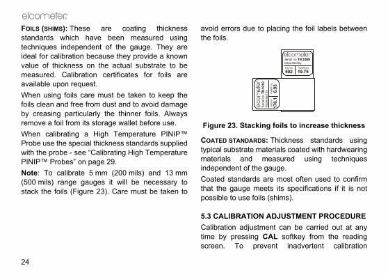
FOILS (SHIMS): These are coating thicknessstandards which have been measured usingtechniques independent of the gauge. They areideal for calibration because they provide a knownvalue of thickness on the actual substrate to bemeasured. Calibration certificates for foils areavailable upon request.When using foils care must be taken to keep thefoils clean and free from dust and to avoid damageby creasing particularly the thinner foils. Alwaysremove a foil from its storage wallet before use.When calibrating a High Temperature PINIP™Probe use the special thickness standards suppliedwith the probe - see “Calibrating High TemperaturePINIP™ Probes” on page 29.Note: To calibrate 5 mm (200 mils) and 13 mm(500 mils) range gauges it will be necessary tostack the foils (Figure 23). Care must be taken to
avoid errors due tothe foils.
Figure 23. Stackin
COATED STANDARDStypical substrate mamaterials and mindependent of the Coated standards that the gauge mepossible to use foils
5.3 CALIBRATIONCalibration adjustmtime by pressing Cscreen. To pre

R
25
air and press CAL softkey
1 - on thickness standard
turns the gauge to the Readinge Calibration Procedure withoutnges.llows the user to take readingsuracy of the current calibration.s do not affect statistical
on calibration standard. Theay a reading. then replace on calibratione displays the average ( ) of
Op_456_3_English.book Page 25 Thursday, May 24, 2007 9:46 PM
adjustment the CAL softkey can be locked(MENU/CALIBRATION LOCKED).The user is guided through the operation of thechosen calibration procedure by means ofinstructions and illustrations on the graphicsscreen. Audible warnings are also provided whenaction is required, e.g. when the probe must beplaced down to get a reading.If the routine is interrupted in any way the previoussettings will be restored until after the full calibrationroutine has been completed or the reset has beencompleted.The screen detail depends on the calibrationmethod chosen, but the calibration is in two steps.The following example is for a Smooth Calibrationadjustment.
Step 11. Hold probe in
(Figure 24).
Figure 24. Step
ESC softkey reScreen from thmaking any chaTEST softkey ato verify the accThese readingcalculations.
2. Place probe gauge will displ
3. Lift probe andstandard. Gaug

icates over-range (Figure 26).ing within range clears this
. Over-range reading
n uncoated standard or zerouge will take and display a
then replace on uncoatedro plate. Gauge displays the
f these readings and the last
Op_456_3_English.book Page 26 Thursday, May 24, 2007 9:46 PM
R
26
these readings and the last reading. Repeatthis action until a stable reading is obtained.
Figure 25. Step 1 - Calibration adjustment on thickness standard
To reject the displayed reading and start thecalibration procedure again, press both the Upand Down softkeys at the same time.To adjust the displayed reading until it iscorrect relative to the thickness standard usethe Up/Down softkeys.
4. Press SET softkey to accept the value.
Note: - - - indTaking a readscreen.
Figure 26
Step 21. Place probe o
plate. The gareading.
2. Lift probe andstandard or zeaverage ( ) o
First reading Second reading
Average
Last

R
27
l display the option to test thee gauge.
EST READINGS screen
NO softkey to complete thestment procedure and return
e reading screen, or proceed tongs - see Taking test readings
Op_456_3_English.book Page 27 Thursday, May 24, 2007 9:46 PM
reading. Repeat this action until a stablereading is obtained.
Figure 27. Step 2 - Calibration adjustment on uncoated sample
To reject the displayed reading and start Step2 of the calibration procedure again, press theReset softkey .
3. Press ZERO softkey to zero the display (Figure28).
Figure 28. Zero the display
4. Press SET softkey to accept this value.
The gauge wilcalibration of th
Figure 29. T
5. Either press calibration adjuthe gauge to thtake test readibelow.
First reading Second reading

ken on a thin standard valuecoated base.
tep 2 - On thin standard
ing will display the average. Thisl for rough surfaces as it allowsrface to be accounted for in theent, therefore improving thege.
- Calibration adjustment on hin standard
g Second reading
Op_456_3_English.book Page 28 Thursday, May 24, 2007 9:46 PM
R
28
Taking test readingsPress YES softkey (see previous section) to taketest readings. This allows the calibration of thegauge to be tested without contributing to thestatistical calculations.
Figure 30. TEST READINGS screen
NEXT softkey returns the gauge to Step 1 of thecalibration adjustment procedure.ESC softkey exits the calibration adjustmentprocedure and returns the gauge to the readingscreen.
Other calibration methodsFor the 2-POINT, ROUGH and SPECIALSUBSTRATE calibration methods Step 2 requires
readings to be tainstead of on an un
Figure 31. S
Repeating the readis particularly usefuvariations in the sucalibration adjustmaccuracy of the gau
Figure 32. Step 2t
First readin
R
29
3 Basic has a Simple Statisticshich calculates and displays af readings as they are taken.ED MENU is active MENU/SEL), press STATS
TATS MENU (Figure 33).
e 33. Stats menu
s available are:dings
tion ariation g g ” on page 31 and “Statisticse 36.
Op_456_3_English.book Page 29 Thursday, May 24, 2007 9:46 PM
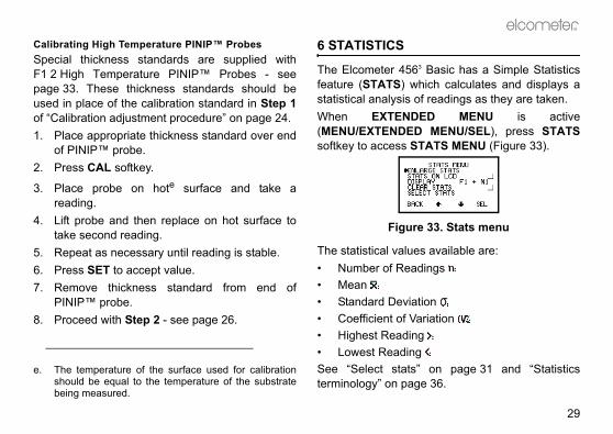
Calibrating High Temperature PINIP™ ProbesSpecial thickness standards are supplied withF1 2 High Temperature PINIP™ Probes - seepage 33. These thickness standards should beused in place of the calibration standard in Step 1of “Calibration adjustment procedure” on page 24.1. Place appropriate thickness standard over end
of PINIP™ probe.2. Press CAL softkey.
3. Place probe on hote surface and take areading.
4. Lift probe and then replace on hot surface totake second reading.
5. Repeat as necessary until reading is stable.6. Press SET to accept value.7. Remove thickness standard from end of
PINIP™ probe.8. Proceed with Step 2 - see page 26.
6 STATISTICS
The Elcometer 456feature (STATS) wstatistical analysis oWhen EXTEND(MENU/EXTENDEDsoftkey to access S
Figur
The statistical value• Number of Rea• Mean • Standard Devia• Coefficient of V• Highest Readin• Lowest ReadinSee “Select statsterminology” on pag
e. The temperature of the surface used for calibrationshould be equal to the temperature of the substratebeing measured.

ntation of the chosen statisticalng screen.
ng screen with all statistics
using dual function probes.he types of readings used in then when a dual function probe is
nd N combinedf
1 and F2 combinedf
re combined a symbol will beReading Screen (Figure 35).
Combined statistics symbol
Op_456_3_English.book Page 30 Thursday, May 24, 2007 9:46 PM
R
30
If you require statistics in batches, or memory forreadings, Elcometer 4563 models Standard and Topprovide this facility. Contact Elcometer or your localElcometer supplier for more details.
6.1 ENLARGE STATSDisplays the chosen statistical values as double-height characters. The example screens (Figure34) appear when all the statistical values areselected. The Up/Down softkeys can be used tomove through the list. OK softkey returns to theReading Screen.
Figure 34. Enlarged statistics
6.2 STATS ON LCDActivates the presevalues on the readi
Figure 35. Readi
6.3 DISPLAYOnly applies whenAllows selection of tstatistical calculatioconnected.Probe OptionsFNF F, N or F aF1 2 F1, F2 or F
f. When readings adisplayed on the

R
31
of probes is available for theating Thickness Gauge. Probes
non-ferrous (N) and dual (FNF) operation are availableuilt-in) or separate options.e fully interchangeable and areard, PINIP™ and miniature
lug-In Integral Probe) is an which plugs in to a separates all the benefits of an integral
ibility of a separate gauge in a
probes permit measurementsricted.
PROBES the thickness of non-magneticic substrates. They can be usedlvanising, enamel, powder paint,ther coatings such as electro-
to steel or iron.
Op_456_3_English.book Page 31 Thursday, May 24, 2007 9:46 PM
6.4 CLEAR STATSResets to zero all statistical values selected inSTATS MENU/DISPLAY.
6.5 SELECT STATSAllows the user to chose which statistical values aredisplayed. The default condition is all values (Figure36).
Figure 36. Select stats menu
Use Up/Down softkeys to move cursor and SELsoftkey to select or deselect the statistical values.
7 PROBES
An extensive rangeElcometer 4563 Cofor ferrous (F), ferrous/non-ferrousas either integral (bSeparate probes aravailable in standformats.PINIP™ format (Pintegral style probegauge. This providegauge and the flexsingle unit.Miniature separatewhere space is rest
7.1 FERROUS (F) F probes measurecoatings on magneton paint, plastic, gahard chrome and oless nickel applied
CHANGEABILITY shows which probes can be
pes of Elcometer 4563 Gauge.
Gauge TypeF N FNF
****
e
igh
straight 45° 90°
Op_456_3_English.book Page 32 Thursday, May 24, 2007 9:46 PM
R
32
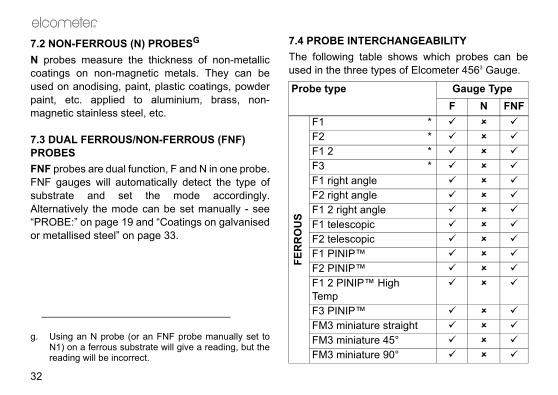
7.2 NON-FERROUS (N) PROBESG
N probes measure the thickness of non-metalliccoatings on non-magnetic metals. They can beused on anodising, paint, plastic coatings, powderpaint, etc. applied to aluminium, brass, non-magnetic stainless steel, etc.
7.3 DUAL FERROUS/NON-FERROUS (FNF) PROBESFNF probes are dual function, F and N in one probe.FNF gauges will automatically detect the type ofsubstrate and set the mode accordingly.Alternatively the mode can be set manually - see“PROBE:” on page 19 and “Coatings on galvanisedor metallised steel” on page 33.
7.4 PROBE INTERThe following tableused in the three ty
g. Using an N probe (or an FNF probe manually set toN1) on a ferrous substrate will give a reading, but thereading will be incorrect.
Probe type
FER
RO
US
F1F2F1 2F3F1 right angleF2 right angleF1 2 right anglF1 telescopicF2 telescopicF1 PINIP™F2 PINIP™F1 2 PINIP™ HTempF3 PINIP™FM3 miniatureFM3 miniatureFM3 miniature

R
33
PERATURE PINIP™
robes are capable of measuringces up to 250°C (480°F). Wearate protective clothing and takevoid bodily contact with the hotsurement.maximum measurement speedrobes - see page 37.cial calibration procedure - seemperature PINIP™ Probes” on
GALVANISED OR EL fixed N1 mode may be used totings on galvanised, aluminiumayed steel substrates.uge to the N1 mode/PROBE).rate the gauge on a sample ofl - see “Calibration adjustment”
Op_456_3_English.book Page 33 Thursday, May 24, 2007 9:46 PM
* indicates probes available for integral typegauges.
7.5 F1 2 PROBESThe F1 2 scale combines the F1 scale with the F2scale in a single probe. The user selects theappropriate range for the work in hand. Theresolution of the gauge is dependent on the scaleselected on the gauge.
7.6 F1 2 HIGH TEMPROBES
These pon surfaappropricare to a
surface during meaDo not exceed the when using these pNote: Refer to spe“Calibrating High Tepage 29.
7.7 COATINGS ONMETALLISED STEThe FNF probe in measure paint coa(Al) or zinc (Zn) spr1. Set the ga
(MENU/SETUP2. Zero and calib
the coated steeon page 22.
NO
N-F
ERR
OU
S
N1 *N2N1 right angleN1A anodiser’sN1 PINIP™NM3 miniature straightNM3 miniature 45°NM3 miniature 90°
DU
AL FNF1 *
FNF1 right angleFNF PINIP™
Probe type Gauge TypeF N FNF

from the downloads section ofebsite, www.elcometer.com.
to PC using optional 456 to PCle - see “PC Connection Cable”
switch on gauge.g Screen is displayed. Screen Wizard’ software andreen instructions.
SCREENme Screen Wizard’ software.
new screen setup’.
d’.
ing on-screen instructions to screen.
Op_456_3_English.book Page 34 Thursday, May 24, 2007 9:46 PM
R
34
Care must be taken to ensure that thecalibration conditions are not affected bychanges in the zinc or aluminium coatingthickness. This can be determined by checkingthe zero over an area of the galvanised ormetal-coated steel. Metal coatings on steelabove 50 µm (2 mil/thou) should be consistentenough to obtain a stable zero on the layer ofmetal.
3. Take readings.
8 PERSONALISED WELCOME SCREEN
A personalised welcome screen can be created anddownloaded into the gauge.Screen dimensions are 128 pixels x 64 pixels. Thewelcome screen is typically used to personalise thegauge with a logo, serial number, user name, etc.This is the first screen displayed when the gauge isswitched on.
8.1 CREATING THE SCREEN1. Download Elcometer ‘Welcome Screen
Wizard’ software. This software is available
free of charge the Elcometer w
2. Connect gaugeconnection cabon page 40.
3. Press key to4. Ensure Readin5. Run ‘Welcome
follow the on-sc
8.2 DELETING THE1. Run the ‘Welco2. Click ‘Next’.3. Select ‘Create a4. Click ‘Next’.5. Select ‘Disable6. Click ‘Next’.Follow the remaindelete the welcome
R
35
o Elcometer. Contact details are - MENU/ABOUT/[email protected] wear. Probe life will
mber of measurements taken the coating is. Probe life can careful positioning of thece.rate and PINIP™ probes caner without the need to returnice.integral probe have to be
ogramming or replacement ifs worn or damaged.
Op_456_3_English.book Page 35 Thursday, May 24, 2007 9:46 PM
9 STORAGE AND TRANSIT
This gauge incorporates a Liquid CrystalDisplay (LCD). If the display is heatedabove 50°C (120°F) it may be damaged.This can happen if the gauge is left in a
car parked in strong sunlight.Always store the gauge in its carrying pouch whenit is not being used. Remove the batteries from the gauge and storethem separately if the gauge is to remain unused fora long period of time. This will prevent damage tothe gauge in the event of malfunction of thebatteries.
10 MAINTENANCE
You own one of the finest hand-held coatingthickness gauges in the world. If looked after, it willlast a lifetime.The gauge does not contain any user-serviceablecomponents. In the unlikely event of a fault, thegauge should be returned to your local Elcometer
supplier or directly tstored in the gaugeWorldwide: sales@Or USA/Canada: inNote: Probes will edepend on the nuand how abrasivebe prolonged byprobe on the surfaReplacement sepabe fitted by the usthe gauge for servGauges with an returned for re-prthe probe become

Number of Readings. The running value for the number of readings taken in a group. In the case of the mode, the Number of Readings is the number of values recorded, not the total number of readings taken.
Standard Deviation. A statistical measure of the spread of values in a group of readings.
Meaning
Op_456_3_English.book Page 36 Thursday, May 24, 2007 9:46 PM
R
36
11 STATISTICS TERMINOLOGY
Term Meaning
COEF OF VARIAT’N
Coefficient of Variation. The standard deviation divided by the mean for a group of readings, expressed as a percentage.
HIGHEST READING
The value of the maximum thickness in a group of readings.
LOWEST READING
The value of the minimum thickness in a group of readings.
MEAN The average of a group of readings; the sum of the individual readings divided by the number of readings.
NO. OF READINGS
STD DEVIATION
Term

R
37
ut outer sleeve: 150°C (300°F)80°C (176°F)
LY2 x LR03 (AAA), alkalineh dryeablei equivalents.
rs continuous use with alkaline00 to 20 000 readings at an
rate Probe (FNF1), 190g z)rate Probe (PINIP™), 155g z)ral Probe, 130g (4.6oz)mm x 70 mm x 35 mm" x 2.76" x 1.38")
to 50°C (32°F to 120°F)ation outside these limits nds upon climatic conditions. impact ABS
Op_456_3_English.book Page 37 Thursday, May 24, 2007 9:46 PM
12 TECHNICAL DATA
12.1 MEASUREMENT SPEED>60 readings per minute.When measuring high temperature materialsmeasurement speed must be reduced to preventoverheating of the probe. The maximummeasurement speed of the High TemperaturePINIP™ probe at 250°C (480°F) is 4 readings perminute.
12.2 MINIMUM SUBSTRATE THICKNESSFerrous: 300 µm (12 mils)Non-ferrous: 100 µm (4 mils)Measurements can be taken on thinner substratesif 2-point calibration is carried out either side of therequired substrate thickness, however gauges willhave reduced range when adjusted for thinsubstrates.
12.3 PROBE OPERATING TEMPERATURESeparate ferrous probes: 150°C (300°F)High temperature PINIP™ probes: 250°C (480°F)
Miniature probes withoAll other probes:
12.4 PHYSICAL
12.5 POWER SUPPInternal batteries, batteries or recharg
Battery life30j hours to 40 houdry batteries. (15 0
Weight (including batteries):
Sepa(6.7oSepa(5.5oInteg
Dimensions: 130(5.12
Gauge operating temperature:
0°C Operdepe
Case: High

ing accessories are optional.e consumable items that may over the lifetime of the gauge.s are available from Elcometer,
eter supplier. At time of orderingales part number which followsach accessory.
extensive range of 456 probesfrom Elcometer, your local
r or the Elcometer website,.
e range 12.5 µm to 20 mm (0.5d customised sets chosen from
pieces: T9904199F pieces: T9904199G4 pieces: T9904199J pieces: T9904199K
Op_456_3_English.book Page 38 Thursday, May 24, 2007 9:46 PM
R
38
average of 8 readings per minute.) Battery life isreduced by one third when using the backlight.
12.6 PACKAGINGThe gauge is packed in cardboard and plasticpackaging. Please ensure that this packaging isdisposed of in an environmentally sensitivemanner. Consult your Local EnvironmentalAuthority for further guidance.
13 ACCESSORIES
The Elcometer 4563 is complete with all the itemsrequired to get started and take measurements.
Many of the followHowever, some arneed to be replacedAll these accessorieor your local Elcomplease quote the sthe description of e
13.1 PROBESFull details of the can be obtained Elcometer suppliewww.elcometer.com
13.2 FOIL SETS
Individual foils in thmil to 790 mils) an
h. Alkaline batteries must be disposed of carefully toavoid environmental contamination. Please consultyour local environmental authority for information ondisposal in your region.Do not dispose of any batteries in fire.
i. Rechargeable batteries can be used if they arecharged outside the gauge.
j. Battery life is reduced to approximately 25% of drybattery life when using rechargeable batteries. Followthe instructions provided by the battery manufacturerwhen charging and disposing of rechargeablebatteries.
2.2 mm (85 mils) 81.3 mm (51 mils) 35.5 mm (220 mils) 15 mm (595 mils) 4

R
39
ith the full range of miniatureable as an accessory.
TERS
hargeable battery powerede with charger. Three charger
g: T95012880
F and N T9997766-
FNF probes): T99913225 (F & N T9997381-
(FNF probes): T99913133
X4569964Blug): X4569964C
X4569964D
Op_456_3_English.book Page 39 Thursday, May 24, 2007 9:46 PM
this range are also available. Consult your localElcometer supplier.
13.3 CALIBRATION CERTIFICATES FOR FOILSCertificates traceable to National Standardsincluding UKAS and NIST are available on request.
13.4 TEST CERTIFICATESA certificate with results of a standard test on knownfoil values over the full range of the probe. Orderusing sales part number TEST-456.
13.5 COATED THICKNESS STANDARDS INCLUDING CERTIFICATE
13.6 PROBE PLACEMENT JIGTo aid probe positioning on small components aprobe placement jig is available and an adapter
suitable for use wprobes is also avail
13.7 PROBE ADAP
13.8 Miniprinter42 column, recMiniprinter completoptions:
Ferrous Standard (4 Values): T995111261Non-Ferrous Standard (4 Values): T995111271Ferrous Standard (2 Values): T995166001Non-Ferrous Standard (2 Values): T995166011
Probe placement ji
Jumbo Hand Grip (probes):Jumbo Hand Grip (V Adapter for pipesprobes):V Adapter for pipes
230V (UK Plug):230V (European P110V (US Plug):

UIPMENT
s a wide range of coatingnd associated paint inspectionf the Elcometer 4563 may also
owing Elcometer products:r thickness gauges
seragement softwaretings thickness gaugesters
rsation contact Elcometer, yourr supplier or visit
Op_456_3_English.book Page 40 Thursday, May 24, 2007 9:46 PM
R
40
Miniprinter spares
13.9 BENCH STANDS
13.10 PC CONNECTION CABLE
Note: A 9-pin to 25-pin adapter may be required forcertain PC RS232 ports.
14 RELATED EQ
Elcometer producethickness gauges aequipment. Users obenefit from the foll• Uncured powde• Coatings analy• Inspection man• Mechanical coa• Appearance tes• Adhesion testeFor further informlocal Elcometewww.elcometer.com
456 to printer connection cable (25-pin):
T45616267
Ribbon Cassettes (Pack of 5): T9769992-Paper Rolls (Box of 20): T9999993-
Integral Probe Version: T45616161Integral/Separate Probe Version: T45616162
456 to PC Connection Cable (9-pin):
T99916217

R
41
Op_456_3_English.book Page 41 Thursday, May 24, 2007 9:46 PM
15 FITTING THE WRIST HARNESS
1. Pass harnessround pin
2. Pass harnessthrough loop
3. Pull tight
easured.
ion in range0 µm to 99.9 µm100 µm to 1500 µm0 mil to 4.99 mils5 mils to 60 mils0 mm to 0.99 mm1.0 mm to 5.0 mm0 mil to 49.9 mils50 mils to 200 mils0 mm to 1.99 mm2 mm to 13 mm0 mil to 99.9 mils100 mils to 500 mils0 µm to 99.9 µm100 µm to 500 µm0 mil to 3.99 mils4 mils to 10 mils0 mm to 1.99 mm2 mm to 25 mm0 mil to 99.9 mils100 mils to 980 mils0 mm to 1.99 mm2 mm to 30 mm0 mil to 99.9 mils100 mils to 1200 mils
Op_456_3_English.book Page 42 Thursday, May 24, 2007 9:46 PM
R
42
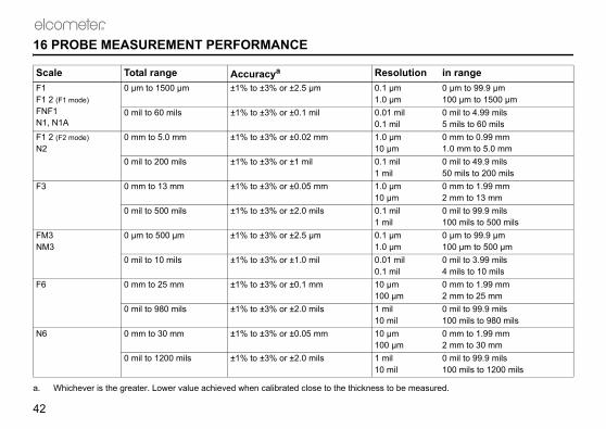
16 PROBE MEASUREMENT PERFORMANCE
Scale Total range Accuracya
a. Whichever is the greater. Lower value achieved when calibrated close to the thickness to be m
ResolutF1F1 2 (F1 mode)FNF1N1, N1A
0 µm to 1500 µm ±1% to ±3% or ±2.5 µm 0.1 µm1.0 µm
0 mil to 60 mils ±1% to ±3% or ±0.1 mil 0.01 mil0.1 mil
F1 2 (F2 mode)N2
0 mm to 5.0 mm ±1% to ±3% or ±0.02 mm 1.0 µm10 µm
0 mil to 200 mils ±1% to ±3% or ±1 mil 0.1 mil1 mil
F3 0 mm to 13 mm ±1% to ±3% or ±0.05 mm 1.0 µm10 µm
0 mil to 500 mils ±1% to ±3% or ±2.0 mils 0.1 mil1 mil
FM3NM3
0 µm to 500 µm ±1% to ±3% or ±2.5 µm 0.1 µm1.0 µm
0 mil to 10 mils ±1% to ±3% or ±1.0 mil 0.01 mil0.1 mil
F6 0 mm to 25 mm ±1% to ±3% or ±0.1 mm 10 µm100 µm
0 mil to 980 mils ±1% to ±3% or ±2.0 mils 1 mil10 mil
N6 0 mm to 30 mm ±1% to ±3% or ±0.05 mm 10 µm100 µm
0 mil to 1200 mils ±1% to ±3% or ±2.0 mils 1 mil10 mil

R
43
inimum mple ameter
Cal foil valuea
specified accuracy under these
mm (0.16”) 250 µm (10 mil)
mm (0.32”) 1 mm (40 mil)
mm (0.55”) 2.5 mm (100mil)
mm (0.24”) 250 µm (10 mil)
mm (0.32”) 250 µm (10 mil)
mm (0.16”) 250 µm (10 mil)
Op_456_3_English.book Page 43 Thursday, May 24, 2007 9:46 PM
17 PROBE CAPABILITIES
17.1 INTEGRAL PROBES
Probe typeMinimum convex surface diameter
Minimum concave surface radius
HeadroomMsadi
a. This is the recommended maximum calibration foil value to achieve themeasurements conditions
F1 (or F1 2 set for F1 operation)
4 mm (0.16”) 25 mm (0.98”) 130 mm (5.1”) 4
F1 2 (set for F2 operation)
4 mm (0.16”) 25 mm (0.98”) 135 mm (5.3”) 8
F3 15 mm (0.59”) 40 mm (1.57”) 150 mm (5.9”) 14
N1 (N) 35 mm (1.38”) 25 mm (0.98”) 130 mm (5.1”) 6
FNF1 (N) 38 mm (1.50”) 25 mm (0.98”) 135 mm (5.3”) 8
FNF1 (F) 4 mm (0.16”) 25 mm (0.98”) 135 mm (5.3”) 4

nimum mple ameter
Cal foil valuea
specified accuracy under these
m (0.16”) 250 µm (10 mil)
m (0.32”) 1 mm (40 mil)
m (0.16”) 250 µm (10 mil)
m (0.32”) 1 mm (40 mil)
m (0.16”) 250 µm (10 mil)
m (0.32”) 1 mm (40 mil)
mm (0.55”) 2.5 mm (100 mil)
x 51 mm" x 2")
5 mm (200 mil)
Op_456_3_English.book Page 44 Thursday, May 24, 2007 9:46 PM
R
44
17.2 SEPARATE FERROUS PROBES
Probe typeMinimum convex surface diameter
Minimum concave surface radius
HeadroomMisadi
a. This is the recommended maximum calibration foil value to achieve themeasurements conditions
F1 (or F1 2 set to F1) 4 mm (0.16”) 25 mm (0.98”) 85 mm (3.35”) 4 m
F1 2 (set to F2) 4 mm (0.16”) 25 mm (0.98”) 89 mm (3.50”) 8 m
F1 Right Angle(or F1 2 set to F1)
4 mm (0.16”) 25 mm (0.98”) 28 mm (1.10”) 4 m
F1 2 Right Angle(set to F2)
4 mm (0.16”) 25 mm (0.98”) 32 mm (1.26”) 8 m
F1 Telescopic 4 mm (0.16”) 25 mm (0.98”) 32 mm (1.26”) 4 m
F1 2 Telescopic 4 mm (0.16”) 25 mm (0.98”) 36 mm (1.42”) 8 m
F3 15 mm (0.59”) 40 mm (1.57”) 102 mm (4.02”) 14
F6 35 mm 170 mm 150 mm 51(2

R
45
nimum mple meter
Cal foil valuea
specified accuracy under these
m (0.24”) 250 µm (10 mil)
m (0.24”) 250 µm (10 mil)
m (0.24”) 250 µm (10 mil)
mm (0.55”) 1 mm (40 mil)
mm Any
Op_456_3_English.book Page 45 Thursday, May 24, 2007 9:46 PM
17.3 SEPARATE NON-FERROUS PROBES
Probe typeMinimum convex surface diameter
Minimum concave surface radius
HeadroomMisadia
a. This is the recommended maximum calibration foil value to achieve themeasurements conditions
N1 35 mm (1.38”) 25 mm (0.98”) 85 mm (3.35”) 6 m
N1 Right Angle 35 mm (1.38”) 25 mm (0.98”) 28 mm (1.10”) 6 m
N1A Anodiser’s Probe
35 mm (1.38”) 25 mm (0.98”) 85 mm (3.35”) 6 m
N2 100 mm (3.97”) 150 mm (5.90”) 85 mm (3.35”) 14
N6 Flat surface 400 mm 160 mm 58

nimum mple ameter
Cal foil valuea
specified accuracy under these
m (0.32”) 250 µm (10 mil)
m (0.16”) 250 µm (10 mil)
m (0.32”) 250 µm (10 mil)
m (0.16”) 250 µm (10 mil)
Op_456_3_English.book Page 46 Thursday, May 24, 2007 9:46 PM
R
46
17.4 SEPARATE DUAL FNF
Probe typeMinimum convex surface diameter
Minimum concave surface radius
HeadroomMisadi
a. This is the recommended maximum calibration foil value to achieve themeasurements conditions
FNF1 (N) 38 mm (1.50”) 25 mm (0.98”) 88 mm (3.46”) 8 m
FNF1 (F) 4 mm (0.16”) 25 mm (0.98”) 88 mm (3.46”) 4 m
FNF1 Right Angle (N)
38 mm (1.50”) 25 mm (0.98”) 34 mm (1.34”) 8 m
FNF1 Right Angle (F)
4 mm (0.16”) 25 mm (0.98”) 34 mm (1.34”) 4 m

R
47
nimum mple meter
Cal foil valuea
specified accuracy under these
m (0.16”) 250 µm (10 mil)
m (0.32”) 1 mm (40 mil)
mm (0.55”) 2.5 mm (100mil)
m (0.24”) 250 µm (10 mil)
m (0.32”) 250 µm (10 mil)
m (0.16”) 250 µm (10 mil)
Op_456_3_English.book Page 47 Thursday, May 24, 2007 9:46 PM
17.5 PINIP™ PROBES
Probe typeMinimum convex surface diameter
Minimum concave surface radius
HeadroomMisadia
a. This is the recommended maximum calibration foil value to achieve themeasurements conditions
F1 (or F1 2 set to F1) 4 mm (0.16”) 60 mm (2.36”) 155 mm (6.10”) 4 m
F1 2 (set to F2) 4 mm (0.16”) 60 mm (2.36”) 159 mm (6.25”) 8 m
F3 15 mm (0.59”) 45 mm (1.77”) 169 mm (6.65”) 14
N1 35 mm (1.38”) 50 mm (1.97”) 155 mm (6.09”) 6 m
FNF1 (N) 38 mm (1.50”) 55 mm (2.17”) 156 mm (6.15”) 8 m
FNF1 (F) 4 mm (0.16”) 55 mm (2.17”) 156 mm (6.14”) 4 m

Minimum access width
Overall length (headroom)
(0.24”) 150 mm (5.91”)
(0.24”) 260 mm (10.24”)
7 mm (0.28”) 145 mm (5.71”)
7 mm (0.28”) 250 mm (9.84”)
7 mm (0.28”) 140 mm (5.51”)
7 mm (0.28”) 245 mm (9.64”)
Op_456_3_English.book Page 48 Thursday, May 24, 2007 9:46 PM
R
48
17.6 SEPARATE MINIATURE FERROUS PROBES
Probe Type
Minimum convex surface diameter
Minimum concave surface radius
Minimum sample diameter
Minimum access height
F, Straight,45 mm (1.77”)
1.5 mm (0.06”) 6.5 mm (0.26”) 3 mm (0.12”) 6 mm
F, Straight,150 mm (5.9”)
1.5 mm (0.06”) 6.5 mm (0.26”) 3 mm (0.12”) 6 mm
F, 45°,45 mm (1.77”)
1.5 mm (0.06”) 6.5 mm (0.26”) 3 mm (0.12”) 18 mm (0.71”)
F, 45°,150 mm (5.9”)
1.5 mm (0.06”) 6.5 mm (0.26”) 3 mm (0.12”) 18 mm (0.71”)
F, 90°,45 mm (1.77”)
1.5 mm (0.06”) 6.5 mm (0.26”) 3 mm (0.12”) 16 mm (0.63”)
F, 90°,150 mm (5.9”)
1.5 mm (0.06”) 6.5 mm (0.26”) 3 mm (0.12”) 16 mm (0.63”)

R
49
Minimum access width
Overall length (headroom)
(0.24”) 150 mm (5.91”)
(0.24”) 260 mm (10.24”)
7 mm (0.28”) 145 mm (5.71”)
7 mm (0.28”) 250 mm (9.84”)
7 mm (0.28”) 140 mm (5.51”)
7 mm (0.28”) 245 mm (9.64”)
Op_456_3_English.book Page 49 Thursday, May 24, 2007 9:46 PM
17.7 SEPARATE MINIATURE NON-FERROUS PROBES
Probe TypeMinimum convex diameter
Minimum concave radius
Minimum sample diameter
Minimum access height
NF, Straight,45 mm (1.77”)
3 mm (0.12”) 25 mm (0.98”) 4 mm (0.16”) 6 mm
NF, Straight,150 mm (5.9”)
3 mm (0.12”) 25 mm (0.98”) 4 mm (0.16”) 6mm
NF, 45°,45 mm (1.77”)
3 mm (0.12”) 25 mm (0.98”) 4 mm (0.16”) 18 mm (0.71”)
NF, 45°,150 mm (5.9”)
3 mm (0.12”) 25 mm (0.98”) 4 mm (0.16”) 18 mm (0.71”)
NF, 90°,45 mm (1.77”)
3 mm (0.12”) 25 mm (0.98”) 4 mm (0.16”) 16 mm (0.63”)
NF, 90°,150 mm (5.9”)
3 mm (0.12”) 25 mm (0.98”) 4 mm (0.16”) 16 mm (0.63”)

. These messages are normally indicated by the message and
akege - return to Elcometer*.uge - remove probe and refit. ists, return to Elcometer*.ge - return to Elcometer*.uge - try new probe.ists, return to Elcometer*.lcometer*.odel F and gauge model N sed with a dual FNF probe. Elcometer* for software
adjustment required.
om electro-magnetic . Elcometer*.
Op_456_3_English.book Page 50 Thursday, May 24, 2007 9:46 PM
R
50
18 ERROR MESSAGES
Under certain conditions the gauge will display error messages (Figure 37)cleared by pressing any one of the softkeys. The cause of the error will beshould be corrected before proceeding.
Error message Causes Action to t#1 - PROBE Probe-to-gauge communication failure. Integral gau
Separate gaIf error pers
#2 - PROBE Corrupt data output from probe. Integral gauSeparate gaIf error pers
#3 - PROBE Internal error. Return to EPROBE UNSUPPORTED
a) Probe is dual FNF, but gauge is ferrous only, or non-ferrous only. See page 31.b) Old gauge software does not support new probe.
a) Gauge mcannot be ub) Return toupgrade.
PROBE CHANGED
Probe has been changed. Calibration
UNSTABLE READING
a) External electro-magnetic interference.b) Gauge faulty.
a) Isolate frinterferenceb) Return to

R
51
cted to gauge
ge off then on again.ists contact Elcometer..ists, return to Elcometer*.lcometer*.
ake
Op_456_3_English.book Page 51 Thursday, May 24, 2007 9:46 PM
* Contact Elcometer or your local Elcometer Supplier to arrange return.
Figure 37. Example error message - no probe is conne
VALUE TOO LARGE
Numerical error. Switch gauIf error pers
CALIBRATION Incorrect calibration calculation. Re-calibrateIf error pers
LANGUAGE MEMORY
Software error. Return to E
Error message Causes Action to t

DDelete last reading 19Dimensions 37DIN 50981 5DIN 50984 5Display
Changing size of fonts 21Character size 10Locking softkeys 21
EElcometer 456
Features 5Overview 4
Error messages 50ESC 25Extended menu
Contents 19
FFactory calibration 16FNF 32Foils 24
Ordering 38
GGalvanised steel 33Gauge information 16
HHigh temperature 33
Op_456_3_English.book Page 52 Thursday, May 24, 2007 9:46 PM
R
52
19 INDEX
Numerics2 Point calibration method 22
AAccessories 38ASTM B 244 5ASTM B 499 5ASTM D 1400 5ASTM D1186 5
BBatteries
Fitting 7Life of 37Precautions 35Rechargeable
Charging 38Life of 7
Specification 37Baud rate 20Beep
Changing volume 21Switching off 21
BS 3900 (C5) 5BS 5411 (11) 5BS 5411 (3) 5BS 5599 5BS EN ISO 1461 5
CCable
PC to gauge 40CAL softkey
Flashing 23Calibration
Adjustment 23Coated standards 23Coated thickness standards 24FNF probes 22Foils 23Locking 15Methods 22Shims 24
Calibration Adjustment 24Procedure, 2Point 28Procedure, Rough 28Procedure, Smooth 25Procedure, Special substrate 28
Calibration certificates 39Calibration methods
2 POINT 22ROUGH 22SET OFFSET 23SPECIAL SUB 22ZERO OFFSET 23
Character size 10Coated thickness standards 24
Spares 39Coatings
On galvanised steel 33On metallised steel 33
Coefficient of Variation 36Computer
Connection cable 40

R
53
Structure 18Metallised steel 33Minimum substrate thickness 37
NNumber of readings 36
OOn/off 9Opening screen
Creating 34Disabling 22
PPackaging 38PINIP probes
Fitting of 8High temperature 33
Power supply 37Printer
Miniprinter 39Printing
Statistical summary 19Printing readings 20Probe positioning jig 39Probes 31
Adapters 39Capabilities 43–49Extending life of 35F (Ferrous)
What used for 31F1 2
High Temperature PINIP 33Substrate selection modes 19
Op_456_3_English.book Page 53 Thursday, May 24, 2007 9:46 PM
Highest reading 36
IInterface 12
RS232 12International gauge settings 16ISO 19840 5, 23ISO 2178 5ISO 2360 5ISO 2808 5
KKeypad 9
LLanguage, selecting 11Lowest reading 36
MMaintenance 35Mean 36Measurement speed 37Menu items
2-POINT 22ABOUT 16AUTO SWITCH OFF 20BACKLIGHT 15BAUD RATE 20BEEP VOLUME 21CAL METHOD 19CALIBRATION LOCKED 15CLEAR STATS 31CONTACT 16
DELETE 19DISPLAY 30ENLARGE STATS 30EXTENDED MENU 18FACTORY CAL 16GAUGE INFORMATION 16HELP 16INTL GAUGE 16LANGUAGES 21LARGE FONTS 21OPENING SCREEN 22OUTPUT 20PRINT/OUTPUT 19PROBE 19PROBE INFORMATION 16RESET 16ROUGH 22RS232 BIT IMAGE 20RS232 PLAIN TEXT 21SELECT STATS 31SET OFFSET 23SETUP 19SMOOTH 22SOFTKEYS LOCKED 21SPECIAL SUB 22STATISTICS 19STATS MENU 29STATS ON LCD 30UNITS 20US GAUGE 17ZERO OFFSET 23
MenusExtended off (simple) 15Extended on 18Overview 15

Substrate selectionAutomatic 20, 32Manual 20, 32
Substrate thicknessMinimum 37
Switching on/off 9Automatically 10, 20
TTemperature
Effect on measurement speed 37High, measuring of 33Operating 37Probes, maximum 37
Test certificates 39Test readings 27Testing calibration of gauge 28Tick box 14
UUnits
Automatic setting of 20Manual setting of 20
Up/Down 14US gauge settings 17
WWeight 37Welcome screen
Creating 34Disabling 22
Wrist harness, fitting of 41
Op_456_3_English.book Page 54 Thursday, May 24, 2007 9:46 PM
R
54
F1 2 overview 33Fitting of 8FNF (Ferrous/Non-ferrous)
Substrate selection modes 19, 32What used for 32
Maximum temperature 37N (Non-ferrous)
What used for 32Performance 42PINIP
What used for 31Replacement of 35Wear of 35Which one to use? 32
QQuick-start 6
RReading screen 10
Typical 13Reading, taking 12Resetting the gauge 16Rough calibration method 22RS232 interface 12
SScale selection, F1 F2 20Screen
Welcome information 10Screen symbols
Battery condition 7Definition of 16
Screen symbols, explanation of 16Set offset 23Setting up the gauge 19Shims 24
Ordering 38Simple menu
Turning on/off 16Smooth calibration method 22Softkey
BACK 15CAL 13
Flashing 14Procedure 24
ESC 25, 28MENU 13NEXT 28SEL 14SET 26, 27TEST 25UP/DOWN 14ZERO 27
Special sub calibration method 22SSPC-PA2 5Standard deviation 36Standards 5
Coated thickness 39Statistics
Activating 19Choice of 31Clearing 31Displaying on screen 30Dual function probes 30Increasing size on display 30Overview 29Terminology 36

R
55
Op_456_3_English.book Page 55 Thursday, May 24, 2007 9:46 PM
ZZero offset calibration method 23