op-amp circuits alan murray. agenda op-amp circuit analysis –non-inverting amplifier circuit...
TRANSCRIPT

Op-Amp Circuits
Alan Murray

Agenda
• Op-Amp circuit Analysis– non-inverting amplifier circuit– inverting amplifier circuit
• ... from first principles– (i.e. only Ohm's Law!)
• Op-Amp "GOLDEN RULES"– simplified Op-Amp circuit analysis– non-inverting amplifier circuit– inverting amplifier circuit
• Positive and Negative Feedback– By analogy and in the Op-Amp context
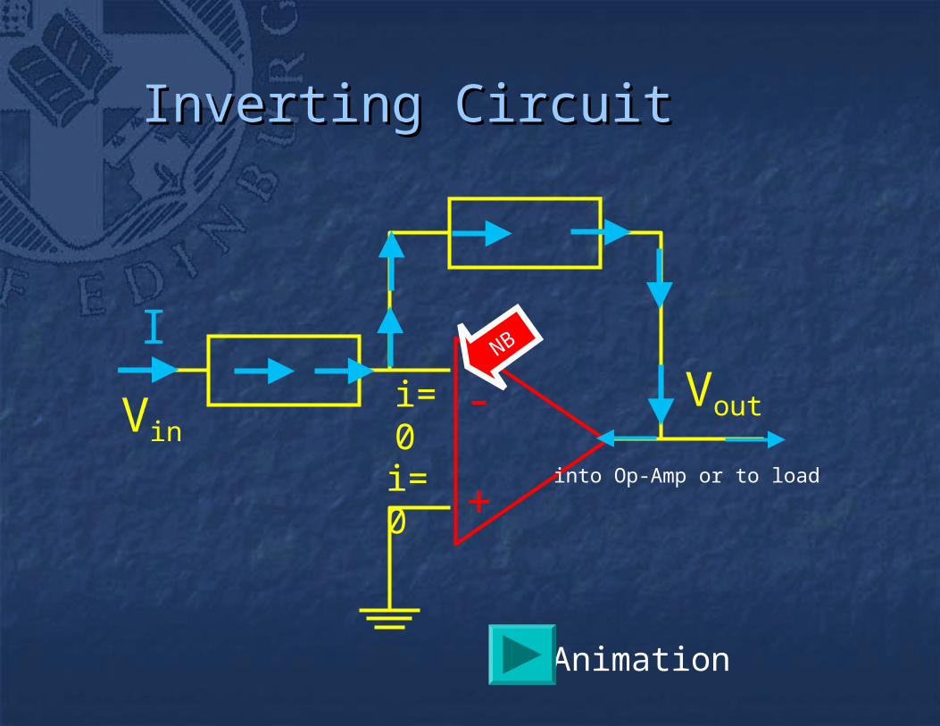
+
- VoutVini=0
i=0
I
into Op-Amp or to load
NB
Inverting CircuitInverting Circuit
Animation
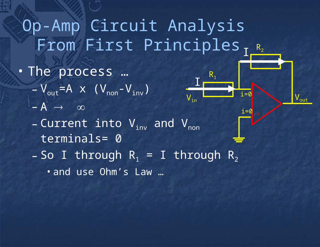
Op-Amp Circuit Analysis From First Principles
• The process …– Vout=A x (Vnon-Vinv)
– A – Current into Vinv and Vnon terminals= 0
– So I through R1 = I through R2 • and use Ohm’s Law …
+
-VoutVin
i=0
i=0
R2
R1
I
I
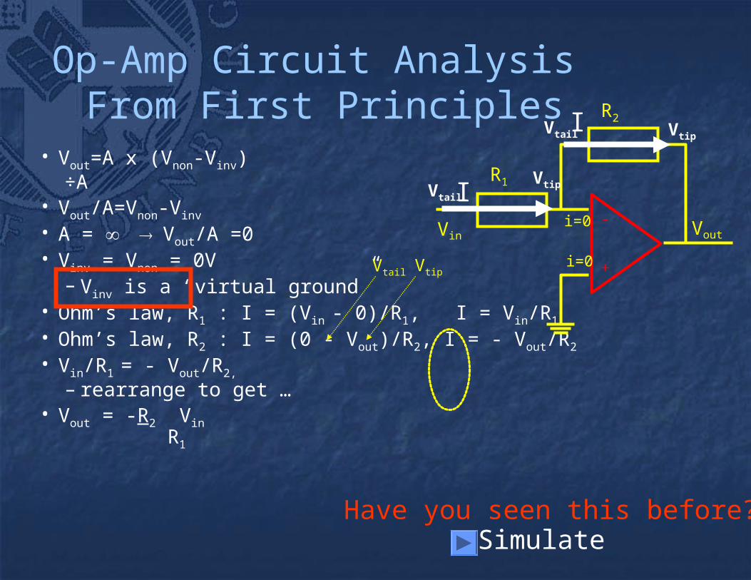
Op-Amp Circuit Analysis From First Principles
• Vout=A x (Vnon-Vinv)÷A
• Vout/A=Vnon-Vinv
• A = Vout/A =0• Vinv = Vnon = 0V
– Vinv is a “virtual ground”• Ohm’s law, R1 : I = (Vin - 0)/R1, I = Vin/R1
• Ohm’s law, R2 : I = (0 - Vout)/R2, I = - Vout/R2
• Vin/R1 = - Vout/R2,
– rearrange to get …• Vout = -R2 Vin
R1
+
-VoutVin
i=0
i=0
R2
R1
Have you seen this before? Simulate
Vtail Vtip
I
I
Vtail
Vtail
Vtip
Vtip

-
+Vout
Vin
i=0
i=0
R2
R1
II
Non-Inverting Circuit
• The process …– Vout=A x (Vnon-Vinv)
– A – I into Vinv and Vnon = 0
– So I in R1 = I in R2 • and use Ohm’s Law …
NB
Animation

-
+Vout
Vin
i=0
i=0
R2
R1
II
Non-Inverting Circuit
• Vout=A x (Vnon-Vinv)
÷A
• Vout/A=Vnon-Vinv
• A = Vout/A =0
• Vnon = Vinv = Vin
• R1 and R2 = a potential divider
R2
R1
Vout
Vinv= Vin
1in out
1 2
RV = V
R +R
1 2out in
1
R +RV = V
R
Here it is again
Simulate

The Golden Rules ANALYSIS OF IDEAL OP-AMP CIRCUITS CAN BE REDUCED TO TWO "GOLDEN RULES" .....
1) No Current enters the "inv" and "non" terminalsof the Op-Amp, Iinv = Inon = 0
2) With negative feedback present,Vout will change such that Vinv = Vnon
Engrave these on your heart ... they are very useful,as long as you remember that they are idealisations
Idealisations? More later – all we mean is that, in reality,
Iinv ≈ Inon ≈ 0
Vinv ≈ Vnon
For an initial analysis of an Op-Amp circuit with negative feedback, use
Iinv = Inon = 0
Vinv = Vnon

Alan Murray – University of EdinburghAlan Murray – University of Edinburgh
Non-Inverting CircuitNon-Inverting CircuitRevisitedRevisited
Golden Rule#1Golden Rule#1• I(RI(R11) I(R) I(R22) =I) =I
• so Rso R11 & R & R22 form forma potential dividera potential divider
VVnonnon = V = Voutout × R × R11/(R/(R11+R+R22))
Golden Rule#2Golden Rule#2• VVinin = V = Vinvinv = V = Vnonnon
VVinin = V = Voutout × R × R11/(R/(R11+R+R22)) VVoutout = V = Vinin × (R × (R11+R+R22)/R)/R11
-
+Vout
Vin
i=0
i=0
R2
R1
II
R2
R1
Vout
Vinv= Vin

Alan Murray – University of EdinburghAlan Murray – University of Edinburgh
Inverting Circuit, by nodal analysisInverting Circuit, by nodal analysis
DO NOT use VDO NOT use Voutout as a node as a node (b) is a boring node(b) is a boring node Sum currents at (a)Sum currents at (a) IIRR + + IIRfRf + + IIinvinv = 0 = 0 IIinvinv = 0 = 0
• Golden RuleGolden Rule (V(Vinin-V-Vinvinv)/R)/R + + (V(Voutout-V-Vinvinv)/R)/Rff + 0 = 0 + 0 = 0 (V(Vinin-V-Vinvinv)/R)/R = = -(V-(Voutout-V-Vinvinv)/R)/Rff VVinvinv = V = Vnonnon = 0 = 0
• Golden RuleGolden Rule VVinin/R = -V/R = -Voutout/R/Rff VVoutout = -V = -VininRRff
RR
R Rf
(a)
(b) +
-
Vin
Vout
Vinv
Vnon

Alan Murray – University of EdinburghAlan Murray – University of Edinburgh
ProcedureProcedure
Check for negative feedbackCheck for negative feedback Apply Golden RulesApply Golden Rules
Using Nodal Analysis?Using Nodal Analysis?
• No Current to input terminalsNo Current to input terminalsof the Op-Ampof the Op-Amp
• VVinvinv = V = Vnonnon
Rearrange to get VRearrange to get Voutout = function(V = function(Vinin))
Alan Murray – University of EdinburghAlan Murray – University of Edinburgh
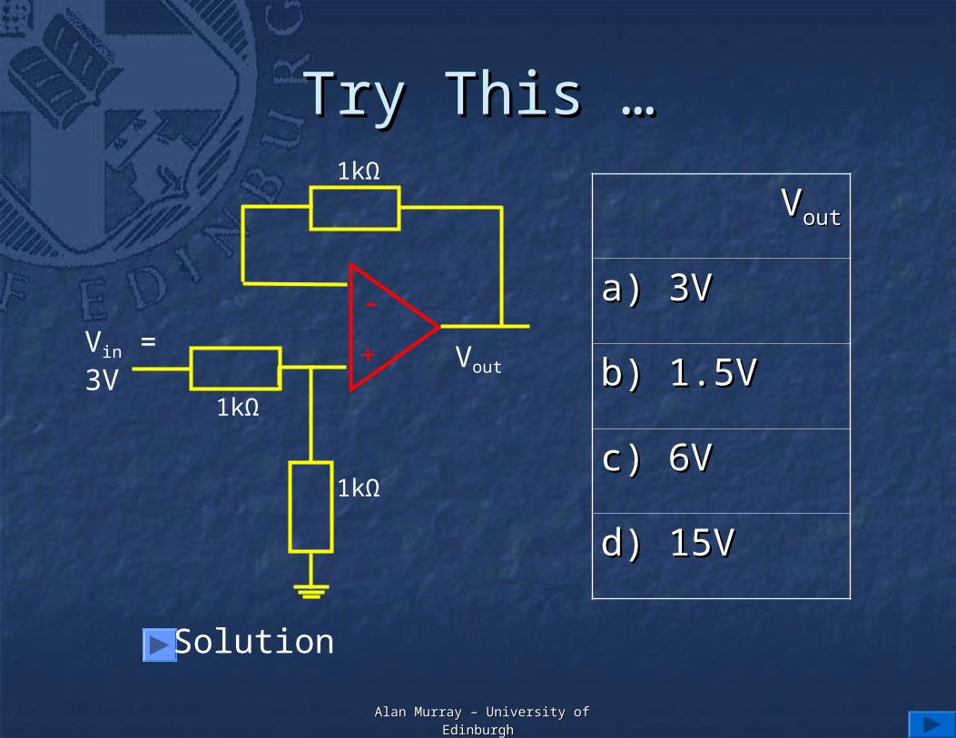
Try This …Try This …
+
-
VoutVin = 3V
1kΩ
1kΩ
1kΩ
VVoutout
a) 3Va) 3V
b) 1.5Vb) 1.5V
c) 6Vc) 6V
d) 15Vd) 15V
Solution
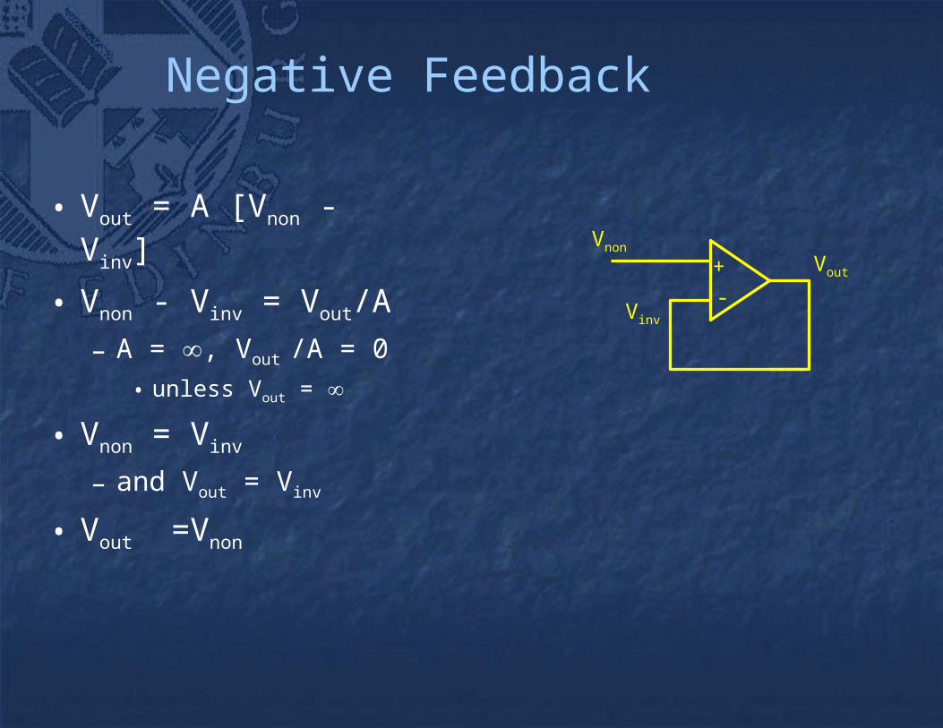
Negative Feedback
• Vout = A [Vnon - Vinv]
• Vnon - Vinv = Vout/A
– A = , Vout /A = 0
• unless Vout =
• Vnon = Vinv
– and Vout = Vinv
• Vout =Vnon
+-
Vnon
Vinv
Vout
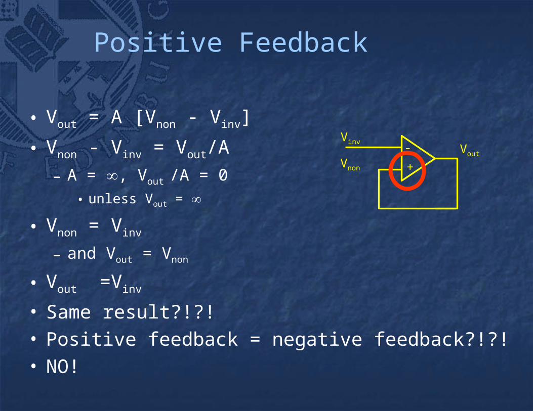
Positive Feedback
• Vout = A [Vnon - Vinv]
• Vnon - Vinv = Vout/A
– A = , Vout /A = 0
• unless Vout =
• Vnon = Vinv
– and Vout = Vnon
• Vout =Vinv
• Same result?!?!• Positive feedback = negative feedback?!?!• NO!
+-
Vnon
VinvVout

Analogy - Central HeatingNegative Feedback
+ THERMOSTAT
TEMPERATURE TOO HIGH
TURN DOWN RADIATOR
-

Analogy - Central HeatingNegative Feedback
+ THERMOSTAT
TEMPERATURE TOO LOW
TURN UP RADIATOR
-
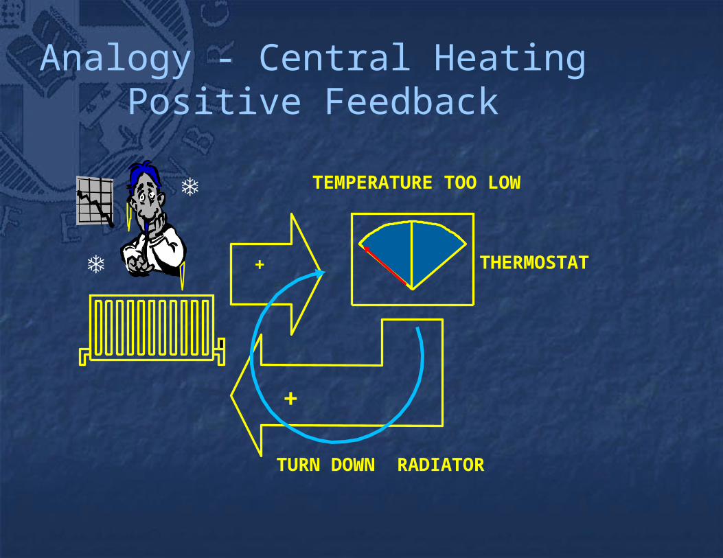
Analogy - Central HeatingPositive Feedback
+ THERMOSTAT
TEMPERATURE TOO LOW
TURN DOWN RADIATOR
+
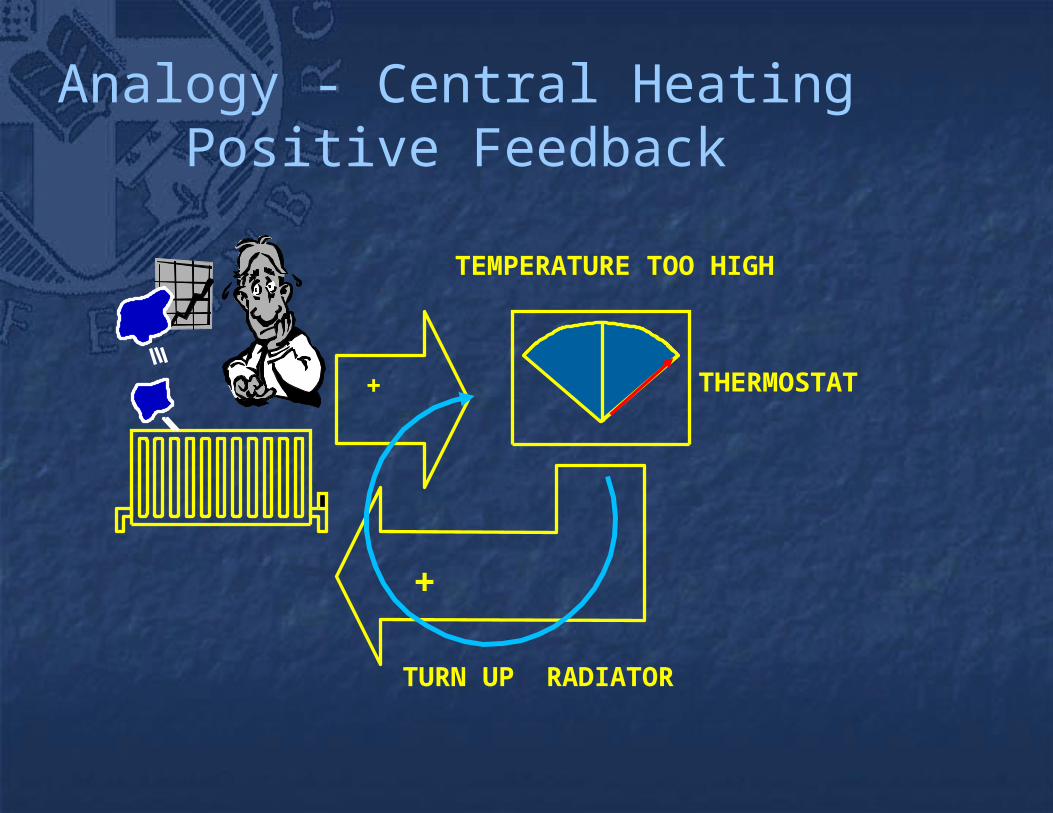
Analogy - Central HeatingPositive Feedback
+ THERMOSTAT
TEMPERATURE TOO HIGH
TURN UP RADIATOR
+

Analogy - Central HeatingPositive or Negative Feedback
+
DO NOTHING
THERMOSTAT
TEMPERATURE EXACTLY CORRECT
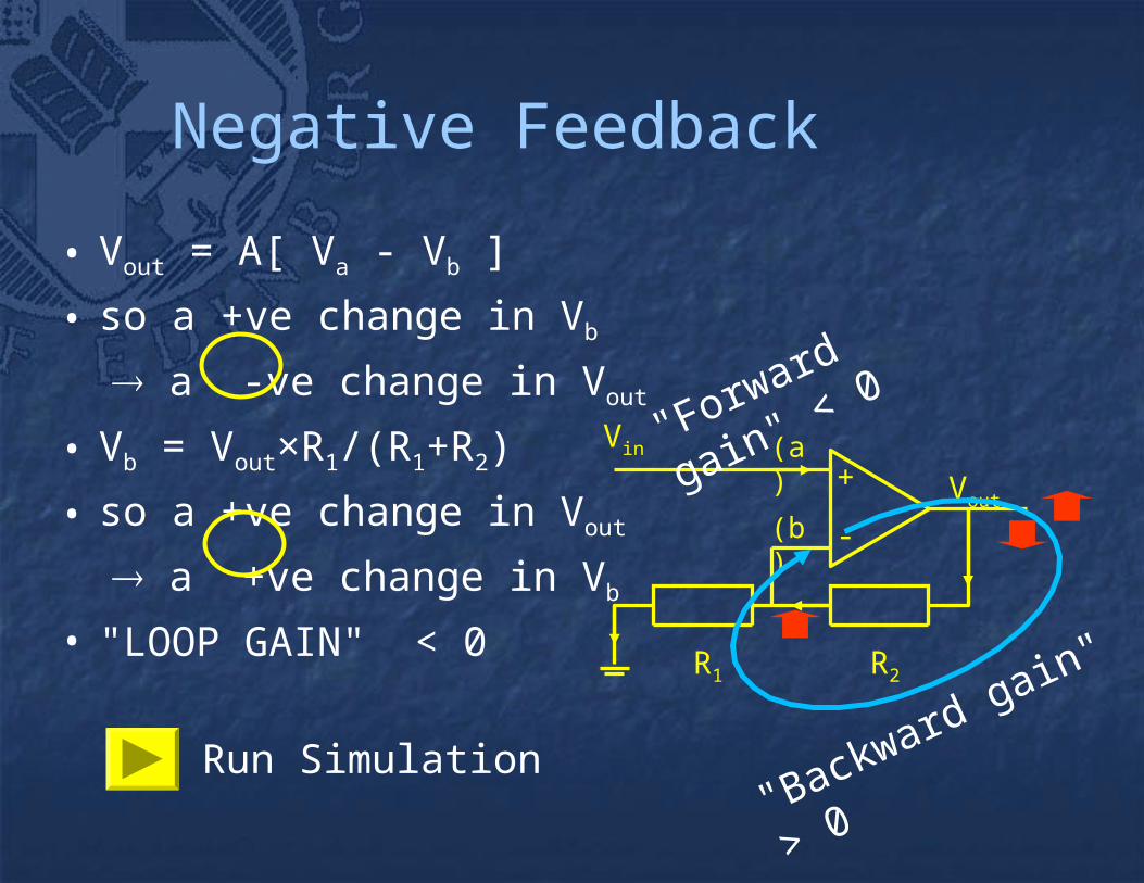
Negative Feedback
• Vout = A[ Va - Vb ]
• so a +ve change in Vb
a -ve change in Vout
• Vb = Vout×R1/(R1+R2)
• so a +ve change in Vout
a +ve change in Vb
• "LOOP GAIN" < 0
+
-
Vin
Vout
(a)
(b)
R2R1
"Forward gain" < 0
"Backward gain" > 0
Run Simulation

Positive Feedback
• Vout = A[ Vb - Va ]
• so a +ve change in Vb
a +ve change in Vout
• Vb = Vout×R1/(R1+R2)
• so a +ve change in Vout
a +ve change in Vb
• "LOOP GAIN" > 0
+
-Vin
Vout
(a)
(b)
R2R1
"Forward gain" > 0
"Backward gain" > 0
Run Simulation

So what happens in an op-Amp circuit with positive feedback?
• At temperature = absolute zero, with a perfectOp-Amp and perfect initial conditions, all is well.
• Otherwise …the smallest disturbance will be amplified and fed back positively
• The Op-Amp's output will head for and then crash into the power supplies (or close to them)
• The output may then stick there or oscillate

Summary
• You should now know ...– How to analyse any simple Op-Amp circuit– (a) From first principles– (b) Using the "Golden Rules"– What is meant by feedback
• positive and negative

Small Reminders
• Power supplies, V+ and V-, are NOT the same as Vinv and Vnon although some books use confusing notation
• No power supplies, no Op-Amp function• Golden rules apply strictly to Ideal Op-Amps
only• Real Op-Amps are not ideal• Golden rules are almost true
– near enough for most purposes