open access nanostructure and impedance spectroscopy of … · open access nanostructure and...
TRANSCRIPT

The Open Inorganic Chemistry Journal, 2009, 3, 47-55 47
1874-0987/09 2009 Bentham Open
Open Access
Nanostructure and Impedance Spectroscopy of Pr0.7Sr0.3Mn1-xMxO3 (M = Fe, Co, Ni; x = 0 and 0.2) Thin Films Grown by Pulsed Laser Deposition
Iratxe de Meatza#,a, Idoia Ruiz de Larramendia, J. Ignacio Ruiz de Larramendia, M. Isabel Arriortuab and Teofilo Rojo*,a
aDepartamento de Química Inorgánica and
bDepartamento de Mineralogía y Petrología, Facultad de Ciencia y Tecno-
logía, Universidad del País Vasco, Apdo.644, 48080 Bilbao, Spain
Abstract: Polycrystalline samples of Pr0.7Sr0.3MnO3 and Pr0.7Sr0.3Mn0.8M0.2O3 (M = Fe, Co, Ni), prepared by the citrate-gel process at 950 ºC, have been deposited on yttria-stabilized zirconia (YSZ) single crystal substrates at 700 ºC by pulsed laser deposition (PLD) for application to thin film solid oxide fuel cell cathodes. The structure of the polycrystalline pow-ders prior to deposition was analyzed by X-ray powder diffraction (XRD) data. The XRD patterns were indexed having a single phase orthorhombic perovskite structure (Pbnm).
The structure and composition of the films deposited by PLD were analyzed by X-ray Diffraction (XRD), X-ray fluores-cence (XRF) and Scanning Electron Microscopy (SEM). All films are polycrystalline, maintaining the initial orthorhom-bic perovskite structure with a marked texture. The surfaces present pyramidal grains with different size distribution, showing a mean particle size of 80 nm. Electrochemical Impedance Spectroscopy (EIS) measurements were carried out on test cells of these materials. The Pr0.7Sr0.3MnO3 thin film presents an Area Specific Resistance (ASR) value of 25.63
·cm2 at 850 ºC while Fe, Co and Ni doped materials show resistances of 6.49, 2.42 and 5.12 ·cm2, respectively.
INTRODUCTION
Solid oxide fuel cells (SOFC) are considered a promising device for energy conversion that exhibit main advantages such as high efficiency and low environmental impact. The energy conversion is direct without any intermediate phase. The most common materials for the SOFC are oxide ion conducting yttria-stabilized zirconia (YSZ) for the electro-lyte, strontium-doped lanthanum manganite (LSM) for the cathode, nickel/YSZ cerment for the anode, and doped lan-thanum chromite or refractory metals as interconnect materi-als.
The traditional SOFC operating at high temperature up to 1000 ºC presents some problems related to the cost of the materials and fabrication. Therefore, an important research is to get lower cost components for operation temperatures under 800 ºC. Accordingly, intermediate temperature solid oxide fuel cells (IT-SOFC), operating in that range of tem-peratures, have attracted much attention in recent years [1].
One of the important SOFC components is the cathode. Some compounds for cathode can exhibit perovskite struc-ture with general formula ABO3 where the A ions are at the corners of the unit cell, the O ions are in the center of the faces of the unit cell and the B ion is located at the octahe-dral interstitial site at the center of the unit cell being coordi-nated to six oxygens. They exhibit a variety of magnetic and electronic properties, displaying good performance as
*Address correspondence to this author at the Departamento de Química Inorgánica, Facultad de Ciencia y Tecnología, Universidad del País Vasco, Apdo.644, 48080 Bilbao, Spain; Tel: +34 94 6012458; Fax: +34 94 6013500; E-mail: [email protected] #current address: CIDETEC, Pº Miramón 196, 20009 Donostia-San Sebastián, Spain.
cathode materials in high temperature solid oxide fuel cells (SOFCs), because of their mixed, electronic and ionic con-ductivity. In particular, rare earth manganite perovskite ox-ides are being widely studied in recent years not only due to their magnetoresistance behaviour but also to their incorpo-ration as cathodes in SOFCs [2]. Cathode materials should present mixed electronic-oxide ion conductivity and pro-longed chemical compatibility with the electrolyte, a stabi-lized zirconia such as 8YSZ can be considered as one of them. There are several problems when designing materials to be used as cathodes, including formation of phases such as pyrochlore, Ln2Zr2O7 or perovskite SrZrO3 at the cathode-electrolyte interface [3,4]. This causes stack degradation, as they show poorer conductivity and different thermal expan-sion coefficient [5]. In the case of the manganites (Ln,A)MnO3, another limiting factor has been shown to be the drop of conductivity values at higher temperatures, due to their predominantly metallic conduction. To avoid some of these problems and, considering that the Pr0.7Sr0.3MnO3 phase is one of the most promising electrode materials [6], we have chosen Praseodymium as lanthanide in the series of compounds studied in this work. Using Sr2+ to partially sub-stitute for Pr cation at the A-site, an important enhancement of the conductivity of the material will be obtained. Further improvements in the performance of the cathode materials can be achieved by co-doping the material, i.e. doping on both A- and B- sites, so different transition metals can also be incorporated in the Mn(III)-Mn(IV) network. This type of materials are also of great interest due to their magnetic properties, because nominal composition Ln1-xAxMnO3 can be drastically altered by either changing the A-site averaged ionic radius (combining elements such as La, Nd, Pr, with Ca, Sr) or by substituting the Mn cation with other 3d transi-tion elements like Fe, Co or Ni [7,8].

48 The Open Inorganic Chemistry Journal, 2009, Volume 3 Meatza et al.
On the other hand, pulsed laser deposition (PLD) has been recently used to fabricate La-Sr-Co-O thin films for application to SOFC [9-16], as using integrated oxide thin films for fuel cell design can reduce the size and cost of cells. Due to its high chemical reactivity with yttria stabi-lized zirconia at high temperature [17], doped lanthanum cobaltite cannot be used as a cathode in high temperature SOFCs. Another important factor to be considered in these thin film cathodes is the porosity, as it could help to increase the gas transport to the reaction sites at the surface of the electrolyte (usually Yttria stabilized Zirconia –YSZ-). There-fore, we have obtained several Pr0.7Sr0.3Mn0.8M0.2O3 (M = Fe, Co, Ni) (PSMF, PSMC and PSMN in the following) thin films by PLD and studied the effect on their properties by incorporation of these transition elements, looking for thin films with high crystallinity and porosity. All these films have been deposited on YSZ single crystal substrates by PLD. X-ray diffraction (XRD), X-ray fluorescence (XRF), Scanning Electron Microscopy (SEM) and electrical conduc-tivity measurements have been performed. The electrical conductivity data have also been compared with those of Pr0.7Sr0.3MnO3 (PSM) thin films obtained by PLD and with La0.8Sr0.2MnO3 (LSM) which is the most common material used as cathode in SOFC devices.
MATERIALS AND METHODOLOGY
Sample Preparation
Polycrystalline samples of composition Pr0.7Sr0.3MnO3 and Pr0.7Sr0.3Mn0.8M0.2O3 (M = Fe, Co, Ni) were synthesized by the citrate-gel process. Appropriate amounts of the start-ing salts [Pr(NO3)3·5H2O; SrCO3; Mn(CH3CO2)2·4H2O; Fe(NO3)3·9H2O; Co(NO3)2·6H2O; Ni(NO3)2·6H2O] and citric acid were dissolved in distilled water and later the suitable volume of ethylene glycol was added. The resulting solution was shaken and heated in a heating plate until the formation of a gel. After that, the gel which was already treated in a sand bath, was calcined at 450 ºC for 3 hours with a 1 º/min rate and then ground and heated in air for 10 h at 850 and 950 ºC. The resulting powders were pressed into pellets and calcined again at 1200 ºC for 10 h.
Using these sintered pellets as targets, Pr0.7Sr0.3MnO3 and Pr0.7Sr0.3Mn0.8M0.2O3 (M = Fe, Co, Ni) films have been de-posited on (100) YSZ single crystal substrates by PLD. The samples were deposited using a LAMBDA PHYSIC Com-pex 102 KrF excimer laser (248 nm, 150 mJ/pulse) at a fre-quency of 15 Hz. The target was placed in a rotating target holder in a vacuum chamber with an initial pressure of 2·10-6 mbar. The YSZ substrates were mounted on a heater and the films were deposited at a substrate temperature of 700 ºC, taking into account the existing literature [9-12] and our pre-vious experience in PLD for similar samples [18]. The tem-perature of the substrate is one of the main parameters affect-ing atomic surface mobility during the deposition process. Oxygen gas was flowed into the chamber in a constant flux during deposition, keeping a pressure of 0.3 mbar. Deposi-tion time was 120 minutes. LSM thin films have been pre-pared using a commercial powder (Praxair) in the same deposition conditions so as to compare their transport prop-erties with the Pr0.7Sr0.3MnO3 and Pr0.7Sr0.3Mn0.8M0.2O3 (M = Fe, Co, Ni) samples. A portion of the targets was randomly collected from a stock-batch for performing the analysis of
the composition using inductively coupled plasma atomic emission spectroscopy (ICP-AES). The nominal and analyti-cal compositions are shown in Table 1.
Table 1. Nominal and Analytical Composition of the
Pr0.7Sr0.3MnO3 and Pr0.7Sr0.3Mn0.8M0.2O3 (M = Fe, Co, Ni) Tar-
gets
Nominal Composition Analytical Composition
Pr0.7Sr0.3MnO3 PSM Pr0.64Sr0.31Mn1.03O3
Pr0.7Sr0.3Mn0.8Fe0.2O3 PSMF Pr0.68Sr0.32Mn0.72Fe0.20O3
Pr0.7Sr0.3Mn0.8Co0.2O3 PSMC Pr0.70Sr0.32Mn0.75Co0.22O3
Pr0.7Sr0.3Mn0.8Ni0.2O3 PSMN Pr0.70Sr0.30Mn0.75Ni0.24O3
Characterization of the Thin Films
The powders and films were characterized by X-ray powder diffraction data, collected using Philips PW1710 and Philips X’Pert-MPD (Bragg-Brentano geometry) diffracto-meters, with CuK radiation, and fitted using the FULL-PROF program [19]. Thin film composition was examined by X-ray fluorescence (XRF) using a Fischerscope X-RAYXDAL-FD instrument. The microstructure of the ob-tained films was observed by scanning electron microscopy (SEM) using a JEOL JSM-6400 microscope at 20 kV accel-erating voltage.
Electrochemical Measurements
Testing cells of manganite/YSZ/manganite were made by deposition of the samples on both sides of a YSZ wafer, in order to measure their transport properties by electrochemi-cal impedance spectroscopy (EIS) and to compare their properties with cells of LSM/YSZ/LSM already prepared by our group [20]. The thickness of the substrates was 0.50 mm, whereas that of the films was about 1.5 μm, and the surface area about 1 cm2. Electrical contacts were platinum grids pressed on both sides of the sample in order to obtain a symmetrical cell. A schematic drawing of the symmetrical testing cell is shown in Fig. (1).
EIS measurements of manganite/YSZ/manganite test cells were conducted using a Solartron 1260 Impedance Analyzer. The frequency range was 10-2 to 106 Hz with a signal amplitude of 50 mV. All these electrochemical ex-periments were performed at equilibrium from room tem-perature up to 850 ºC, under zero dc current intensity and under air over a cycle of heating and cooling. Impedance
Fig. (1). Schematic drawing of the symmetrical testing cell.
Nanostructure and Impedance Spectroscopy The Open Inorganic Chemistry Journal, 2009, Volume 3 49
diagrams were analyzed and fitted using the Zview software. Resistance and capacitance values from the fitting of each semicircle in the EIS measurements were obtained by least square refinement.
RESULTS AND DISCUSSION
Characterization of the Thin Films
The results of the elemental analysis carried out by X-ray fluorescence method are reported in Table 2. The measured Sr content was always lower than the corresponding value of
the target samples. In the XRF studies, it can be observed that the peaks corresponding to the Sr and Zr are in the same position, precluding a quantitative and qualitative evaluation of the Sr content on these surfaces. Nevertheless, the values for the rest of the elements confirm that the composition of the used targets is maintained in the obtained films.
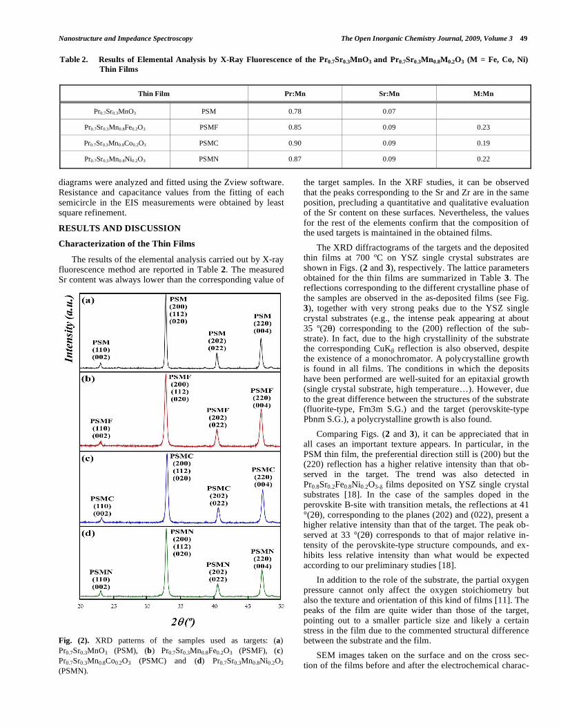
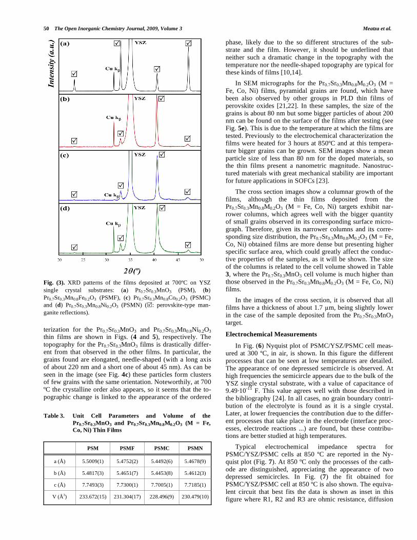
The XRD diffractograms of the targets and the deposited thin films at 700 ºC on YSZ single crystal substrates are shown in Figs. (2 and 3), respectively. The lattice parameters obtained for the thin films are summarized in Table 3. The reflections corresponding to the different crystalline phase of the samples are observed in the as-deposited films (see Fig. 3), together with very strong peaks due to the YSZ single crystal substrates (e.g., the intense peak appearing at about 35 º(2 ) corresponding to the (200) reflection of the sub-strate). In fact, due to the high crystallinity of the substrate the corresponding CuK reflection is also observed, despite the existence of a monochromator. A polycrystalline growth is found in all films. The conditions in which the deposits have been performed are well-suited for an epitaxial growth (single crystal substrate, high temperature…). However, due to the great difference between the structures of the substrate (fluorite-type, Fm3m S.G.) and the target (perovskite-type Pbnm S.G.), a polycrystalline growth is also found.
Comparing Figs. (2 and 3), it can be appreciated that in all cases an important texture appears. In particular, in the PSM thin film, the preferential direction still is (200) but the (220) reflection has a higher relative intensity than that ob-served in the target. The trend was also detected in Pr0.8Sr0.2Fe0.8Ni0.2O3- films deposited on YSZ single crystal substrates [18]. In the case of the samples doped in the perovskite B-site with transition metals, the reflections at 41 °(2 ), corresponding to the planes (202) and (022), present a higher relative intensity than that of the target. The peak ob-served at 33 °(2 ) corresponds to that of major relative in-tensity of the perovskite-type structure compounds, and ex-hibits less relative intensity than what would be expected according to our preliminary studies [18].
In addition to the role of the substrate, the partial oxygen pressure cannot only affect the oxygen stoichiometry but also the texture and orientation of this kind of films [11]. The peaks of the film are quite wider than those of the target, pointing out to a smaller particle size and likely a certain stress in the film due to the commented structural difference between the substrate and the film.
SEM images taken on the surface and on the cross sec-tion of the films before and after the electrochemical charac-
Table 2. Results of Elemental Analysis by X-Ray Fluorescence of the Pr0.7Sr0.3MnO3 and Pr0.7Sr0.3Mn0.8M0.2O3 (M = Fe, Co, Ni)
Thin Films
Thin Film Pr:Mn Sr:Mn M:Mn
Pr0.7Sr0.3MnO3 PSM 0.78 0.07
Pr0.7Sr0.3Mn0.8Fe0.2O3 PSMF 0.85 0.09 0.23
Pr0.7Sr0.3Mn0.8Co0.2O3 PSMC 0.90 0.09 0.19
Pr0.7Sr0.3Mn0.8Ni0.2O3 PSMN 0.87 0.09 0.22
Fig. (2). XRD patterns of the samples used as targets: (a) Pr0.7Sr0.3MnO3 (PSM), (b) Pr0.7Sr0.3Mn0.8Fe0.2O3 (PSMF), (c) Pr0.7Sr0.3Mn0.8Co0.2O3 (PSMC) and (d) Pr0.7Sr0.3Mn0.8Ni0.2O3 (PSMN).
50 The Open Inorganic Chemistry Journal, 2009, Volume 3 Meatza et al.
terization for the Pr0.7Sr0.3MnO3 and Pr0.7Sr0.3Mn0.8Ni0.2O3 thin films are shown in Figs. (4 and 5), respectively. The topography for the Pr0.7Sr0.3MnO3 films is drastically differ-ent from that observed in the other films. In particular, the grains found are elongated, needle-shaped (with a long axis of about 220 nm and a short one of about 45 nm). As can be seen in the image (see Fig. 4c) these particles form clusters of few grains with the same orientation. Noteworthily, at 700 ºC the crystalline order also appears, so it seems that the to-pographic change is linked to the appearance of the ordered
phase, likely due to the so different structures of the sub-strate and the film. However, it should be underlined that neither such a dramatic change in the topography with the temperature nor the needle-shaped topography are typical for these kinds of films [10,14].
In SEM micrographs for the Pr0.7Sr0.3Mn0.8M0.2O3 (M = Fe, Co, Ni) films, pyramidal grains are found, which have been also observed by other groups in PLD thin films of perovskite oxides [21,22]. In these samples, the size of the grains is about 80 nm but some bigger particles of about 200 nm can be found on the surface of the films after testing (see Fig. 5e). This is due to the temperature at which the films are tested. Previously to the electrochemical characterization the films were heated for 3 hours at 850ºC and at this tempera-ture bigger grains can be grown. SEM images show a mean particle size of less than 80 nm for the doped materials, so the thin films present a nanometric magnitude. Nanostruc-tured materials with great mechanical stability are important for future applications in SOFCs [23].
The cross section images show a columnar growth of the films, although the thin films deposited from the Pr0.7Sr0.3Mn0.8M0.2O3 (M = Fe, Co, Ni) targets exhibit nar-rower columns, which agrees well with the bigger quantity of small grains observed in its corresponding surface micro-graph. Therefore, given its narrower columns and its corre-sponding size distribution, the Pr0.7Sr0.3Mn0.8M0.2O3 (M = Fe, Co, Ni) obtained films are more dense but presenting higher specific surface area, which could greatly affect the conduc-tive properties of the samples, as it will be shown. The size of the columns is related to the cell volume showed in Table 3, where the Pr0.7Sr0.3MnO3 cell volume is much higher than those observed in the Pr0.7Sr0.3Mn0.8M0.2O3 (M = Fe, Co, Ni) films.
In the images of the cross section, it is observed that all films have a thickness of about 1.7 m, being slightly lower in the case of the sample deposited from the Pr0.7Sr0.3MnO3 target.
Electrochemical Measurements
In Fig. (6) Nyquist plot of PSMC/YSZ/PSMC cell meas-ured at 300 ºC, in air, is shown. In this figure the different processes that can be seen at low temperatures are detailed. The appearance of one depressed semicircle is observed. At high frequencies the semicircle appears due to the bulk of the YSZ single crystal substrate, with a value of capacitance of 9.49·10-11 F. This value agrees well with those described in the bibliography [24]. In all cases, no grain boundary contri-bution of the electrolyte is found as it is a single crystal. Later, at lower frequencies the contribution due to the differ-ent processes that take place in the electrode (interface proc-esses, electrode reactions ...) are found, but these contribu-tions are better studied at high temperatures.
Typical electrochemical impedance spectra for PSMC/YSZ/PSMC cells at 850 ºC are reported in the Ny-quist plot (Fig. 7). At 850 ºC only the processes of the cath-ode are distinguished, appreciating the appearance of two depressed semicircles. In Fig. (7) the fit obtained for PSMC/YSZ/PSMC cell at 850 ºC is also shown. The equiva-lent circuit that best fits the data is shown as inset in this figure where R1, R2 and R3 are ohmic resistance, diffusion
Fig. (3). XRD patterns of the films deposited at 700ºC on YSZ single crystal substrates: (a) Pr0.7Sr0.3MnO3 (PSM), (b) Pr0.7Sr0.3Mn0.8Fe0.2O3 (PSMF), (c) Pr0.7Sr0.3Mn0.8Co0.2O3 (PSMC) and (d) Pr0.7Sr0.3Mn0.8Ni0.2O3 (PSMN) ( : perovskite-type man-ganite reflections).
Table 3. Unit Cell Parameters and Volume of the
Pr0.7Sr0.3MnO3 and Pr0.7Sr0.3Mn0.8M0.2O3 (M = Fe,
Co, Ni) Thin Films
PSM PSMF PSMC PSMN
a (Å) 5.5009(1) 5.4752(2) 5.4492(6) 5.4678(9)
b (Å) 5.4817(3) 5.4651(7) 5.4453(8) 5.4612(3)
c (Å) 7.7493(3) 7.7300(1) 7.7005(1) 7.7185(1)
V (Å3) 233.672(15) 231.304(17) 228.496(9) 230.479(10)

Nanostructure and Impedance Spectroscopy The Open Inorganic Chemistry Journal, 2009, Volume 3 51
Fig. (4). SEM images of the surface and cross section of the Pr0.7Sr0.3MnO3 films: (a,b,c) before and (d,e,f) after the electrochemical charac-terization.
Fig. (5). SEM images of the surface and cross section of the Pr0.7Sr0.3Mn0.8Ni0.2O3 films: (a,b,c) before and (d,e,f) after the electrochemical characterization.
in the perovskite, and dissociative adsorption on the elec-trode surface, respectively [13]. The R2 and R3 have con-stant phase elements (CPE) in parallel to simulate the distri-bution of relaxation time in the real system. Both semicircles are overlapped, which difficults the analysis of the results obtained for each process. At high temperatures and high frequencies, the small arc appeared which, according to sev-eral authors, is independent of temperature [25]. Low-frequency arc is ascribed to gas diffusion [25].
There has been carried out the study of the influence on every electrochemical processes of different transition metals incorporated in the Mn(III)-Mn(IV) network, looking for an improvement of the properties of the materials. The Nyquist plots of the different cells in air at 850ºC appear in Fig. (8). In this figure the different processes that can be observed at high temperatures are presented (the contributions due to the electrolyte do not appear), appreciating a series of depressed semicircles. The contribution of the processes in the elec-
(a) (b) (c)
(d) (e) (f)
(a) (b) (c)
(d) (e) (f)

52 The Open Inorganic Chemistry Journal, 2009, Volume 3 Meatza et al.
trode appears at high temperature, at medium and low fre-quencies. The higher electrode resistance is obtained for the sample un-doped in the perovskite B-site (Pr0.7Sr0.3MnO3 - PSM), being the minor one for the Co doped material. PSM material shows very poor oxide ion conduction, but its elec-tronic conductivity is high. The PSM total electrode resis-tance, Rel, thus consists of the sum of surface exchange re-sistance and ionic transport resistance (R2 + R3). But, when doping the B-site of the PSM material with different transi-tions metals, the reduction of Mn(IV) to M(III) occurs, dis-appearing the extrinsic electronic conductivity. Doping on the B-site with Fe, Co and Ni, the non-stoichiometry of oxy-gen is increased, resulting in an improvement of the ionic conduction. Also, it must be taken into account that in thin films, the electrochemical reaction is controlled mainly by the chemical or electrochemical process at the electrode sur-face [26] and these B-site doped films have a smaller particle
size (about 80 nm), which is directly related to a major active surface. A deeper understanding of the oxygen reduction kinetics for different cathode materials is highly desired but complicated by the rather ill-defined structure of the thin film electrodes.
Fig. (8). Typical impedance diagrams obtained with mangan-ite/YSZ half cells, under air, at 850 ºC. The impedance data are plotted after electrolyte ohmic drop correction.
The Arrhenius plot for the two resistances RLF and RMF, measured on PSMC electrode is shown in Fig. (9). The tem-perature dependence of the surface resistance (RLF) is rela-tively strong, as quantitatively expressed by the activation energy of 1.97 eV between 550 and 850°C. The activation energy of RMF (related to interfacial resistance), on the other hand, is 1.96 eV.
Fig. (9). Low (RLF) and Medium Frequency (RMF) resistances as a function of temperature between 550 and 850°C, measured on the PSMC/YSZ/PSMC cells.
In Fig. (10), the Arrhenius plot of capacitances of the different contributions is shown for PSMC thin film on YSZ single crystal substrate. A study was carried out according to the methodology proposed by Schouler et al. [24], where the
Fig. (6). Typical impedance diagram obtained for PSMC/YSZ half cells, under air, at 300 ºC. (inset: equivalent circuit used for fitting data). The numbers by data points are frequency logarithms.
Fig. (7). Typical impedance diagram obtained for PSMC/YSZ half cells, under air, at 850 ºC. (inset: equivalent circuit used for fitting data). The numbers by data points are frequency logarithms.

Nanostructure and Impedance Spectroscopy The Open Inorganic Chemistry Journal, 2009, Volume 3 53
thermal evolution of the relaxation frequencies, fr, is inde-pendent from the geometric characteristics of the sample, which enabled us to associate the different contributions to their respective processes.
Fig. (10). Arrhenius plots of capacitances (C) for the PSMC/YSZ/PSMC cells under air and zero dc conditions (HF: high frequencies; MF: medium frequencies; LF: low frequencies). At high frequencies (HF) the different electrolyte contri-butions are appreciated, being observable only at low tem-peratures. As the substrates are YSZ single crystals, only the contribution of the bulk of the electrolyte is appreciated. The capacitance value assigned to the YSZ single crystal electro-lyte bulk process is 10-11 F·cm-3. On the other hand, at lower frequencies two different contributions can be seen for the electrodic processes which are associated with MIEC (mixed ionic and electronic conductor) behavior [27]. The oxygen reduction mechanism on porous MIEC electrodes may in-volve several processes such as charge transfer at the current collector/electrode interface and electrode/electrolyte inter-faces, oxygen exchange at the electrode surface, bulk and surface diffusion of oxygen species and gas phase diffusion (Fig. 11).
Oxygen reduction at MIECs is a particular type of elec-trochemistry since the bulk of the electrode directly partici-pates to the reaction. It has been proved that the charge trans-fer step at the electrode/electrolyte is facile. To be able to assign every contribution with its respective semicircle and in order to understand the oxygen reduction mechanism, it is therefore necessary to know the defect chemistry of these materials at and out of equilibrium, so it will be necessary to perform more measurements such as the characterization of the thin films in different oxygen partial pressures. Those studies will be carried out in further works under way.
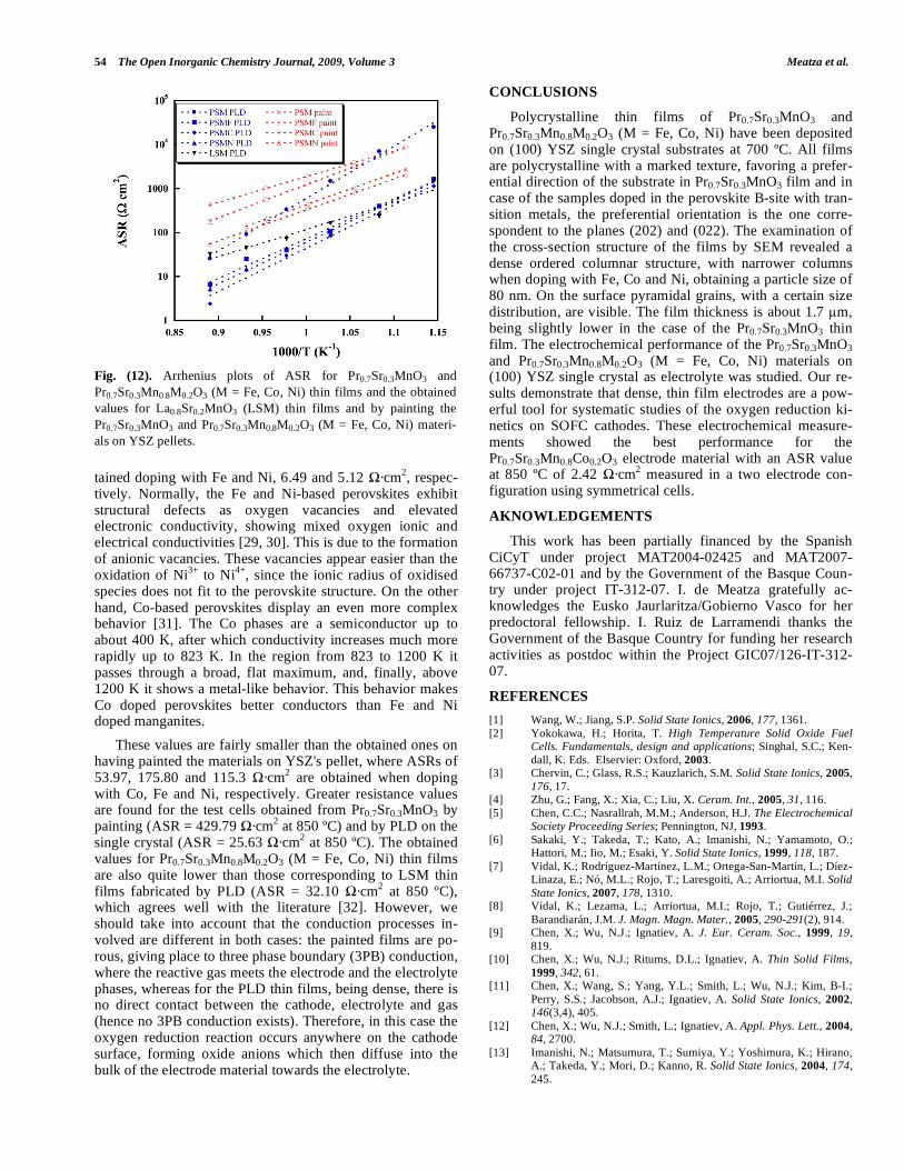
The Area Specific Resistance (ASR) is deduced from the relation: ASR = Relectrode · SurfaceArea/2. The Arrhenius plots of the ASR values for manganite/YSZ/manganite half cells are given in Fig. (12). The ASR data have also been compared with those of the manganites painted on YSZ pel-lets and with La0.8Sr0.2MnO3 (LSM), which is the most common material used as cathode in SOFC devices, obtained by PLD.
It is known that the reaction is kinetically limited by ad-sorption, incorporation and bulk diffusion steps while charge transfer is facile [28]. The results on the comparison of the obtained results by PLD and by painting the samples suggest that the surface pathway contributes in a non-negligible manner to the overall process in these materials. The conduc-tion process in thin films could be investigated with two phase boundary (2PB) contribution because the films are very dense and no triple phase boundaries (3PB) are found. Therefore the quantitative conclusions of this work cannot be transposed to conventional porous electrodes. As schemati-cally illustrated in Fig. (11), oxygen reduction at thin dense films is one-dimensional with well-controlled bulk diffusion length. In the case of porous electrodes, the diffusion length is unknown and depends on kinetics of both the surface and bulk pathways.
In all cases, ASR values remain over 1 ·cm2. The sam-ple doped on the perovskite B-site with Co (PSMC) presents a lower ASR value, 2.42 ·cm2 at 850 ºC, than the ones ob-
Fig. (11). Comparison of oxygen reduction pathways at thin dense (left) and thick porous (right) electrodes. Thin dense electrodes enable to control the bulk diffusion length of the one-dimensional oxygen reduction process.
54 The Open Inorganic Chemistry Journal, 2009, Volume 3 Meatza et al.
tained doping with Fe and Ni, 6.49 and 5.12 ·cm2, respec-tively. Normally, the Fe and Ni-based perovskites exhibit structural defects as oxygen vacancies and elevated electronic conductivity, showing mixed oxygen ionic and electrical conductivities [29, 30]. This is due to the formation of anionic vacancies. These vacancies appear easier than the oxidation of Ni3+ to Ni4+, since the ionic radius of oxidised species does not fit to the perovskite structure. On the other hand, Co-based perovskites display an even more complex behavior [31]. The Co phases are a semiconductor up to about 400 K, after which conductivity increases much more rapidly up to 823 K. In the region from 823 to 1200 K it passes through a broad, flat maximum, and, finally, above 1200 K it shows a metal-like behavior. This behavior makes Co doped perovskites better conductors than Fe and Ni doped manganites.
These values are fairly smaller than the obtained ones on having painted the materials on YSZ's pellet, where ASRs of 53.97, 175.80 and 115.3 ·cm2 are obtained when doping with Co, Fe and Ni, respectively. Greater resistance values are found for the test cells obtained from Pr0.7Sr0.3MnO3 by painting (ASR = 429.79 ·cm2 at 850 ºC) and by PLD on the single crystal (ASR = 25.63 ·cm2 at 850 ºC). The obtained values for Pr0.7Sr0.3Mn0.8M0.2O3 (M = Fe, Co, Ni) thin films are also quite lower than those corresponding to LSM thin films fabricated by PLD (ASR = 32.10 ·cm2 at 850 ºC), which agrees well with the literature [32]. However, we should take into account that the conduction processes in-volved are different in both cases: the painted films are po-rous, giving place to three phase boundary (3PB) conduction, where the reactive gas meets the electrode and the electrolyte phases, whereas for the PLD thin films, being dense, there is no direct contact between the cathode, electrolyte and gas (hence no 3PB conduction exists). Therefore, in this case the oxygen reduction reaction occurs anywhere on the cathode surface, forming oxide anions which then diffuse into the bulk of the electrode material towards the electrolyte.
CONCLUSIONS
Polycrystalline thin films of Pr0.7Sr0.3MnO3 and Pr0.7Sr0.3Mn0.8M0.2O3 (M = Fe, Co, Ni) have been deposited on (100) YSZ single crystal substrates at 700 ºC. All films are polycrystalline with a marked texture, favoring a prefer-ential direction of the substrate in Pr0.7Sr0.3MnO3 film and in case of the samples doped in the perovskite B-site with tran-sition metals, the preferential orientation is the one corre-spondent to the planes (202) and (022). The examination of the cross-section structure of the films by SEM revealed a dense ordered columnar structure, with narrower columns when doping with Fe, Co and Ni, obtaining a particle size of 80 nm. On the surface pyramidal grains, with a certain size distribution, are visible. The film thickness is about 1.7 m, being slightly lower in the case of the Pr0.7Sr0.3MnO3 thin film. The electrochemical performance of the Pr0.7Sr0.3MnO3 and Pr0.7Sr0.3Mn0.8M0.2O3 (M = Fe, Co, Ni) materials on (100) YSZ single crystal as electrolyte was studied. Our re-sults demonstrate that dense, thin film electrodes are a pow-erful tool for systematic studies of the oxygen reduction ki-netics on SOFC cathodes. These electrochemical measure-ments showed the best performance for the Pr0.7Sr0.3Mn0.8Co0.2O3 electrode material with an ASR value at 850 ºC of 2.42 ·cm2 measured in a two electrode con-figuration using symmetrical cells.
AKNOWLEDGEMENTS
This work has been partially financed by the Spanish CiCyT under project MAT2004-02425 and MAT2007-66737-C02-01 and by the Government of the Basque Coun-try under project IT-312-07. I. de Meatza gratefully ac-knowledges the Eusko Jaurlaritza/Gobierno Vasco for her predoctoral fellowship. I. Ruiz de Larramendi thanks the Government of the Basque Country for funding her research activities as postdoc within the Project GIC07/126-IT-312-07.
REFERENCES
[1] Wang, W.; Jiang, S.P. Solid State Ionics, 2006, 177, 1361. [2] Yokokawa, H.; Horita, T. High Temperature Solid Oxide Fuel
Cells. Fundamentals, design and applications; Singhal, S.C.; Ken-dall, K. Eds. Elservier: Oxford, 2003.
[3] Chervin, C.; Glass, R.S.; Kauzlarich, S.M. Solid State Ionics, 2005, 176, 17.
[4] Zhu, G.; Fang, X.; Xia, C.; Liu, X. Ceram. Int., 2005, 31, 116. [5] Chen, C.C.; Nasrallrah, M.M.; Anderson, H.J. The Electrochemical
Society Proceeding Series; Pennington, NJ, 1993. [6] Sakaki, Y.; Takeda, T.; Kato, A.; Imanishi, N.; Yamamoto, O.;
Hattori, M.; Iio, M.; Esaki, Y. Solid State Ionics, 1999, 118, 187. [7] Vidal, K.; Rodríguez-Martínez, L.M.; Ortega-San-Martín, L.; Díez-
Linaza, E.; Nó, M.L.; Rojo, T.; Laresgoiti, A.; Arriortua, M.I. Solid
State Ionics, 2007, 178, 1310. [8] Vidal, K.; Lezama, L.; Arriortua, M.I.; Rojo, T.; Gutiérrez, J.;
Barandiarán, J.M. J. Magn. Magn. Mater., 2005, 290-291(2), 914. [9] Chen, X.; Wu, N.J.; Ignatiev, A. J. Eur. Ceram. Soc., 1999, 19,
819. [10] Chen, X.; Wu, N.J.; Ritums, D.L.; Ignatiev, A. Thin Solid Films,
1999, 342, 61. [11] Chen, X.; Wang, S.; Yang, Y.L.; Smith, L.; Wu, N.J.; Kim, B-I.;
Perry, S.S.; Jacobson, A.J.; Ignatiev, A. Solid State Ionics, 2002, 146(3,4), 405.
[12] Chen, X.; Wu, N.J.; Smith, L.; Ignatiev, A. Appl. Phys. Lett., 2004, 84, 2700.
[13] Imanishi, N.; Matsumura, T.; Sumiya, Y.; Yoshimura, K.; Hirano, A.; Takeda, Y.; Mori, D.; Kanno, R. Solid State Ionics, 2004, 174, 245.
Fig. (12). Arrhenius plots of ASR for Pr0.7Sr0.3MnO3 and Pr0.7Sr0.3Mn0.8M0.2O3 (M = Fe, Co, Ni) thin films and the obtained values for La0.8Sr0.2MnO3 (LSM) thin films and by painting the Pr0.7Sr0.3MnO3 and Pr0.7Sr0.3Mn0.8M0.2O3 (M = Fe, Co, Ni) materi-als on YSZ pellets.

Nanostructure and Impedance Spectroscopy The Open Inorganic Chemistry Journal, 2009, Volume 3 55
[14] Mori, D.; Oka, H.; Suzuki, Y.; Sonoyama, N.; Yamada, A.; Kanno, R.; Sumiya, Y.; Imanishi, N.; Takeda, Y. Solid State Ionics, 2006, 177, 535.
[15] Imanishi, N.; Sumiya, Y.; Yoshimura, K.; Matsumura, T.; Hirano, A.; Takeda, Y.; Mori, D.; Kanno, R. Solid State Ionics, 2006, 177, 749.
[16] Pederson, L.R.; Singh, P.; Zhou, X.-D. Vacuum, 2006, 80, 1066. [17] Figueiredo, F.M.; Labrincha, J.A.; Frade, J.R.; Marques, F.M.B.
Solid State Ionics, 1997, 101, 343. [18] Ruiz de Larramendi, I.; Lopez Antón, R.; Ruiz de Larramendi, J.I.;
Baliteau, S.; Mauvy, F.; Grenier, J.C.; Rojo, T. J. Power Sources, 2007, 169(1), 35.
[19] Rodríguez-Carvajal, J. Physica B, 1993, 55, 192. [20] Ruiz de Larramendi, I.; Ortiz, N.; Lopez Antón, R.; Ruiz de Larra-
mendi, J.I.; Rojo, T. J. Power Sources, 2007, 171, 747. [21] Scarisoreanu, N.; Craciun, F.; Dinescu, G.; Verardi, P.; Dinescu,
M. Thin Solid Films 2004, 453-454, 399. [22] Wu, W.; Wong, K.H.; Choy, C.L. J. Phys. D: Appl. Phys., 1999,
32, L57. [23] Kleinlogel, C.; Gauckler, L.J. Solid State Ionics, 2000, 135, 567.
[24] Schouler, E.J.L.; Mesbahi, N.; Vitter, G. Solid State Ionics, 1983, 9
& 10, 989. [25] Zhu, G.; Fang, X.; Xia, C.; Liu, X. Ceram. Int., 2005, 31, 115. [26] Kawada, T.; Masuda, K.; Suzuki, J.; Kaimai, A.; Kawamura, K.;
Nigara, Y.; Mizusaki, J.; Yugami, H.; Arashi, H.; Sakai, N.; Yoko-kawa, H. Solid State Ionics, 1999, 121(1-4), 271.
[27] Mauvy, F.; Lalanne, C.; Bassat, J.M.; Grenier, J.C.; Zhao, H.; Huo, L.; Stevens, P. J. Electrochem. Soc., 2006, 153(8), A1547.
[28] Adler, S.B.; Lane, J.A.; Steele, B.C.H. J. Electrochem. Soc., 1996, 143, 3554.
[29] Kharton, V.V.; Viskupa, A.A.; Naumovicha, E.N.; Tikhonovicha, V.N. Mater. Res. Bull., 1999, 34, 1311.
[30] Huang, K.; Lee, H.Y.; Goodenough, J.B. J. Electrochem. Soc.,
1998, 145(8), 3220. [31] Khattak, C. P.; Wang, F. F. Y. In Handbook of the Physics and
Chemistry of Rare Earths; Gschneider, K. A. Jr.; Eyring, L., Eds.; North-Holland Publisher: Amsterdam, 1979.
[32] Endo, A.; Ihara, M.; Komiyama, H.; Yamada, K. Solid State Ionics, 1996, 86-88, 1191.
Received: September 24, 2008 Revised: January 20, 2009 Accepted: March 16, 2009
© Meatza et al.; Licensee Bentham Open.
This is an open access article licensed under the terms of the Creative Commons Attribution Non-Commercial License
(http://creativecommons.org/licenses/by-nc/3.0/) which permits unrestricted, non-commercial use, distribution and reproduction in any medium, provided the
work is properly cited.