open access static strength of tubular t-joint with …€¦ · focused on the analysis of tubular...
TRANSCRIPT

The Open Ocean Engineering Journal, 2011, 4, 65-70 65
1874-835X/11 2011 Bentham Open
Open Access
Static Strength of Tubular T-joint with Reinforced Chord Under In-plane Bending Load
Song Shengzhi and Shao Yongbo*
School of Civil Engineering, Yantai University, China, 264005
Abstract: Recent research on the static strength of axially loaded tubular T-joints with chord reinforcement shows that
appropriately proportioned reinforced length and thickness can significantly improve the static strength. This paper
extends the numerical study to chord reinforced tubular T-joint subjected to in-plane bending load. Firstly, various aspects
of the FEA strategy such as material properties, element type, mesh density, and load condition are addressed. Afterwards,
4 T-joint models are analyzed to prove that increasing the thickness of the chord is effective to increase the static strength.
Finally, the parametric investigation, which involves the length and the thickness of the reinforced chord segment,
is conducted. From the parametric study, the most effective values of the length and the thickness of the reinforced chord
are suggested.
Keywords: Tubular T-joint, Static strength, In-plane Bending, Finite element analysis, Failure mode, Parameter analysis.
INTRODUCTION
Steel circular hollow sections are used extensively in
offshore structures due to their excellent structural and
mechanical properties such as high strength versus weight
ratio, high buoyancy, low drag coefficient, small corrosion
surface area and so on. In these structures, the hollow section
members are jointed together by welding the profiled ends of
the braces onto the circumference of the chord. As high
stress concentration exists near the weld toe, failure
generally occurs near the weld on the hollow section surface.
In recent years, a lot of research work on improving the
static strength of axially loaded tubular T-joints by using
reinforcing methods has been done [1-4]. Most work is
focused on the analysis of tubular joints under axial load,
and the research on tubular joints under in-plane bending
load is relatively few, especially on reinforced tubular joints.
In the literature, Y.S. Choo had studied the bearing capacity
of doubler plate [5] and collar plate [10] reinforced X-joints
under in-plane bending load, and established the parametric
equations for assessing the static strength. As in-plane
bending load is also a common loading type for tubular
joints subjected to in practical tubular structures, it is also
meaningful to study the static behavior of tubular T-joints
under in-plane bending. Reinforcing the critical region is used to improve the
static strength for tubular T-joint. Generally, reinforcing method can be classified into internal reinforcement and external reinforcement. The aim of this study is to increase the radial stiffness of chord, and so as to improve the bearing capacity of tubular T-joints. The internal reinforcement of chord is divided into internal ring reinforcement, internal plate reinforcement, increasing the thickness of chord
*Address correspondence to this author at the School of Civil Engineering,
Yantai University, China; Tel: +86 535 6902606; Fax: +86 535 690255;
E-mail: [email protected]
reinforcement, and so on. In this paper, the method by increasing the thickness of chord near the weld toe is used to improve the static strength of tubular T-joint. This method of internal reinforcement for tubular T-joint can not affect any appearance of the T-joint and can maintain its aesthetic characteristics.
FINITE ELEMENT ANALYSES FOR TUBULAR T-JOINT WITH CHORD REINFORCEMENT
Geometry of a Chord Reinforced Tubular Joint
The geometry of a tubular T-joint reinforced with increasing chord thickness at the intersection is shown in Fig. (1). The thickness and the length of the reinforced chord are denoted by Tc and Lc respectively. Some normalized geometrical parameters generally used for describing a tubular T-joint are also listed in Fig. (1).
Finite Element Modeling
The finite element model is built by software ABAQUS
which is a professional finite element analysis software to
analyse complex and difficult nonlinear problems. For the
steel material with obvious plastic flow feature, if the
bilinear hardening model is adopted, the capacity of T-joint
will be overestimated. Therefore, the ideal elastic-plastic
model provided by software ABAQUS is used to simulate
steel material. It meets Von Mises yield stress criterion. The
material properties of the brace and the chord are defined as
206,000 N/mm2
for modulus of elasticity (E) and 0.3 for
Poisson’s ratio (v). The yield stress of the steel material (fy)
is equal to 345 N/mm2. 3-D structural solid elements (C3D8I)
with 8 nodes are used to model the brace and the chord.
From experience of previous work [6], the effects of the
weld on static strength have been found to be insignificant.
Therefore, the effects of weld in the intersection and the
residual stress on the bearing capacity of the tubular T -joints
are ignored in the finite element analyses. The geometric

66 The Open Ocean Engineering Journal, 2011, Volume 4 Shengzhi and Yongbo
nonlinear analysis is used throughout the analysis process.
As the hot spot stress located at the weld, to obtain accurate
numerical results and to increase computational efficiency,
the mesh around the weld toe is refined while a relatively
coarse mesh is used far away from the weld toe [7]. The ap-
proximate element size in the refine region is from 10mm to
20mm, and that in the coarse region is from 45mm to 60mm.
The mesh of a typical T -joint is shown in Fig. (2). To avoid
the local buckling of chord ends, two rigid plates are tied to
the ends of chord (as shown in Fig. 3). Both ends for the
chord are assumed as hinge joint by restraining the middle
lines of the two end rigid plates (as shown in Fig. 3). The
horizontal load is applied at a reference point which is lo-
cated at the center of brace end. The reference point couples
with the nodes at the brace end. The horizontal degree of
freedom of the reference point is limited by using the dis-
placement control method, and the degrees of freedom of the
reference point in other directions are released. The horizon-
tal displacement of the reference point is controlled to obtain
the applied reaction force.
NUMERICAL ANALYSIS
Comparison Between Reinforced Model and
Un-Reinforced Model
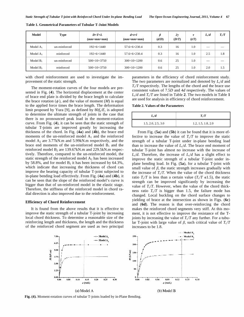
The computational results of the reinforced models are compared with those of the un-reinforced models to verify that the above presented reinforcement method is effective to improve static strength of a tubular T-joint. The parameters of the reinforced and un-reinforced T-joint models are shown in Table 1. Where is the brace-to-chord diameter ratio, 2 is the chord diameter-to-chord wall thickness ratio and is the chord wall thickness-to-brace wall thickness ratio. The specimens are divided into two groups. The un-reinforced and reinforced models of each group have the same geomet-ric dimensions and material properties. The models of the two groups have different values of the parameters to com-pare with each other. The values of and are taken from the range of validity which is presented by CIDECT guide [8] arbitrarily. The lengths of chord and brace adopt 7.5D and 5d respectively. Two models of each group without and
Fig. (1). Geometrical model of tubular T-joint with chord un-reinforced and reinforced.
Fig. (2). Mesh of a tubular T-joint.
Fig. (3). Load and boundary condition of tubular T-joint.
Static Strength of Tubular T-joint with Reinforced Chord Under In-plane Bending Load The Open Ocean Engineering Journal, 2011, Volume 4 67
with chord reinforcement are used to investigate the im-provement of the static strength.
The moment-rotation curves of the four models are pre-sented in Fig. (4). The horizontal displacement at the center of brace end plate is divided by the brace length to calculate the brace rotation ( ), and the value of moment (M) is equal to the applied force times the brace length. The deformation limit proposed by Yura [9], as defined by 80fy/E, is adopted to determine the ultimate strength of joints in the case that there is no pronounced peak load in the moment-rotation curve. From Fig. (4), it can be seen that the static strength of tubular T-joints are improved greatly by increasing the thickness of the chord. In Fig. (4a) and (4b), the brace end moments of the un-reinforced model A1 and the reinforced model A2 are 3.77kN.m and 5.99kN.m respectively, and the brace end moments of the un-reinforced model B1 and the reinforced model B2 are 139.67kN.m and 229.5kN.m respec-tively. Therefore, compared to the un-reinforced model, the static strength of the reinforced model A2 has been increased by 58.8%, and for model B2 it has been increased by 64.3%, which indicate that increasing the thickness of chord can improve the bearing capacity of tubular T-joint subjected to in-plane bending load effectively. From Fig. (4a) and (4b), it can be seen that the slope of the reinforced model’s curve is bigger than that of un-reinforced model in the elastic stage. Therefore, the stiffness of the reinforced model in chord ra-dial direction is also improved due to the reinforcement.
Efficiency of Chord Reinforcement
It is found from the above results that it is effective to improve the static strength of a tubular T-joint by increasing local chord thickness. To determine a reasonable size of the reinforcing length and thickness, the length and the thickness of the reinforced chord segment are used as two principal
parameters in the efficiency of chord reinforcement study. The two parameters are normalized and denoted by Lc/d and Tc/T respectively. The lengths of the chord and the brace use consistent values of 7.5D and 4d respectively. The values of Lc/d and Tc/T are listed in Table 2. The two models in Table 1 are used for analysis in efficiency of chord reinforcement.
Table 2. Values of the Parameters
Lc/d Tc/T
1.5, 2.0, 2.5, 3.0 1.2, 1.5, 1.8, 2.0
From Fig. (5a) and (5b) it can be found that it is more ef-
fective to increase the value of Tc/T to improve the static
strength of a tubular T-joint under in-plane bending load
than to increase the value of Lc/d. The brace end moment of
tubular T-joint has almost no increase with the increase of
Lc/d. Therefore, the increase of Lc/d has a slight effect to
improve the static strength of a tubular T-joint under in-
plane bending load. In Fig. (5a), for a tubular T-joint with
small value of , the static strength increases gradually with
the increase of Tc/T. When the value of the chord thickness
ratio Tc/T is less than a certain value (Tc/T 1.5), the static
strength can be improved significantly by increasing the
value of Tc/T. However, when the value of the chord thick-
ness ratio Tc/T is bigger than 1.5, the failure mode has
changed. Local buckling on the chord surface changes to
yielding of brace at the intersection as shown in Figs. (6c)
and (6d). The reason is that over-reinforcing the chord
makes the reinforced chord segments very stiff. At this mo-
ment, it is not effective to improve the resistance of the T-
joints by increasing the value of Tc/T any further. For a tubu-
lar T-joint with large value of , such critical value of Tc/T increases to be 1.8.
Table 1. Geometrical Parameters of Tubular T-Joint Models
Model Type D T L
(mm mm mm)
d t l
(mm mm mm)
(d/D)
2
(D/T)
(t/T)
Lc/d Tc/T
Model A1 un-reinforced 192 6 1440 57.6 6 230.4 0.3 16 1.0 — —
Model A2 reinforced 192 6 1440 57.6 6 230.4 0.3 16 1.0 2.5 1.8
Model B1 un-reinforced 500 10 3750 300 10 1200 0.6 25 1.0 — —
Model B2 reinforced 500 10 3750 300 10 1200 0.6 25 1.0 2.0 1.5
Fig. (4). Moment-rotation curves of tubular T-joints loaded by in-Plane Bending.

68 The Open Ocean Engineering Journal, 2011, Volume 4 Shengzhi and Yongbo
Failure Mode Analysis
As shown in Fig. (6a), the un-reinforced tubular T-joint model fails in a form of local buckling on the chord surface around the brace and chord intersection. However, as shown in Fig. (6b), due to increasing the thickness of chord locally, the stiffness of chord in the radial direction has been im-proved. The deformation of the chord surface decreases gradually with the increase of Tc/T. The brace at the intersec-tion performs as yielding gradually. When the value of Tc/T exceeds a certain critical value, the deformation on the chord surface around the weld toe becomes quite small (as shown in Fig. (6c) and (6d)), and the brace near the intersection fails in a form of yielding completely since the present rein-forced chord segment becomes much stronger.
Parametric Analysis
Based on the above analysis, it can be found that the in-fluence of Tc/T for improving the static strength of a tubular T-joint is greater than that of Lc/d. To investigate the effect of some geometrical parameters and Tc/T, parametric study is carried out. Geometrical parameters (i.e., the thickness of chord T, the brace/chord diameter ratio , the chord diame-ter/thickness ratio 2 ) and Tc/T are used as parameters in the parametric study. The values of these parameters are listed in
Table 3. Additionally, the reinforced chord length ratio (Lc/d) and the brace/chord thickness ratio (t/T) are consistent, and the values are 2.5 and 1.0 respectively. The lengths of the chord and the brace still use consistent values of 7.5D and 4d respectively.
Table 3. Values of the Parameters
Tc/T T (mm)
0.3, 0.45, 0.6, 0.8 10, 16, 25, 35 1.2, 1.5, 1.8, 2.0 6, 10, 15
As shown in Fig. (7), when the value of the chord thick-ness ratio (Tc/T) is less than a certain value (Tc/T 1.5), the chord thickness ratio (Tc/T) has a basically linear effect on the improvement of the static strength of a tubular T-joint under in-plane bending load. If the value of Tc/T exceeds a critical value, increasing the value of Tc/T has no effect to improve the in-plane bending capacity of a tubular T-joint.
Fig. (8) and Fig. (9) show that it has small effect on im-proving the in-plane bending capacity of a tubular T-joint with small values of and by increasing the value of Tc/T. The reason is that a smaller value of means that the brace is very thin when compared with that of the chord diameter and a small value of means that the thickness of the chord is
Fig. (5). Efficiency of the reinforced length and thickness.
Fig. (6). The deformation of tubular T-joint.

Static Strength of Tubular T-joint with Reinforced Chord Under In-plane Bending Load The Open Ocean Engineering Journal, 2011, Volume 4 69
very large when compared with that of the radius, the stiff-ness in the radial direction of the chord is relatively larger, therefore, the failure modes both perform as local buckling in the brace, as shown in Fig. (6c) and (d). It also can be observed clearly from Fig. (8) and Fig. (9).
In Fig. (8), when the value of is less than 0.3, the criti-cal value of Tc/T is 1.5. When a tubular T-joint with large value of (0.3 0.5), the critical value of Tc/T is 1.8. When the value of is more than 0.5, the critical value of Tc/T increases gradually with the increase of . The static strength of a tubular T-joint under in-plane bending load
increases remarkably with the increase of . When the value of is relatively larger, the static strength of a tubular T-joint can be improved significantly by increasing the value of Tc/T. However, increasing the value of Tc/T is not effec-tive to improve the static strength of a tubular T-joint with a small value of .
As shown in Fig. (9), the effect of parameter on the in-plane bending capacity of a tubular T-joint can be seen as a linear relationship approximately. The increase of can im-prove the in-plane bending capacity of tubular T-joint sig-nificantly. Similarly, parameter has the same effect as pa-rameter on the in-plane bending capacity of tubular T-joint. When parameter takes a small value, it has small in-fluence on improving the static strength by increasing the value of Tc/T. However, the increasing efficiency is signifi-cant with a large value of .
CONCLUSIONS
Based on the finite element analysis and parametric study
on tubular T-joints with chord reinforcement, if the geometry
parameters of a tubular T-joint are in a certain range
(0.3 0.8; 10 35), the following conclusions can be drawn.
(1) Increasing chord thickness locally is effective to im-
prove the static strength of a tubular T-joint under in-plane bending load.
(2) It is more effective to increase the value of Tc/T to
improve the static strength of a tubular T-joint under
in-plane bending load than to increase the value of Lc/d.
(3) The value of Tc/T should be in a certain range. Other-
wise, it is not effective to improve the static strength
of the tubular T-joints by increasing the value of Tc/T
any further. For a tubular T-joint with small value of
( 0.3), the critical value of Tc/T is 1.5. For a tubular
T-joint with large value of (0.3 0.5), the critical
value of Tc/T is 1.8. For a tubular T-joint with a larger
value of ( 0.5), the critical value of Tc/T increases gradually with the increase of .
(4) When the values of and are relatively larger, in-
creasing the value of Tc/T can improve the static
strength of a tubular T-joint greatly. However, the in-
creasing efficiency is not obvious with small values of and .
REFERENCES
[1] Y. B. Shao, “Study on reinforcing methods for welded tubular joints structures”, J. Yantai Univ (Natural Science and Engineering
Edition), vol. 22, no. 4, pp. 312-320, 2009. [2] M. M. K. Lee, and A. Llewelyn-Parry, “Offshore tubular T-joints
reinforced with internal plain annular ring stiffeners”, J. Struct. Eng. ASCE., vol. 130, no. 6, pp. 942-951, 2004.
[3] T. Li, Y. B. Shao, and J. C. Zhang, “Study on static strength of tubular joints reinforced with horizontal inner plate”, Steel Con-
struct, vol. 24, no. 123, pp. 25-29, 2009. [4] Y. B. Shao, J. C. Zhang, Z. H. Qiu, and J. J. Shang, “Strength
analysis of large-scale multiplanar tubular joints with inner-plate reinforcement”. Int. J. Space Struct., vol. 24, no. 3, pp. 161-177,
2009. [5] Y. S. Choo, J. X., Liang, G. J. van der Vegte and J. Y. R. Liew.
“Static strength of doubler plate reinforced CHS X-joints loaded by
Fig. (7). Effect of chord thickness ratio Tc/T on the in-plane bend-
ing capacity ( =0.3, =16).
Fig. (8). Effect of on the in-plane bending capacity (T=10, =25).
Fig. (9). Effect of on the in-plane bending capacity (T=10,
=0.6).

70 The Open Ocean Engineering Journal, 2011, Volume 4 Shengzhi and Yongbo
in-plane bending”. J. Construct. Steel Res., vol. 60, pp.1725-1744,
2004. [6] M. M. K. Lee, and Llewelyn-Parry, ‘‘Strength of ring stiffened
tubular T-joints in offshore structures—A numerical parametric study”, J. Construct. Steel Res., vol. 51, pp. 239-264, 1999a.
[7] G. J. Van der Vegte, Y. S. Choo, J. X. Liang, N. Zettlemoyer and J. Y. R. Liew, “Static strength of T-joints reinforced with doubler or
collar plates. II: numerical simulations”, J. Struct. Eng. ASCE., vol. 131, no. 1, pp. 129-138, 2005.
[8] X. L. Zhao, S. Herion, J. A. Packer, R. Puthli, G. Sedlacek, J. War-denier, K. Weynand, A. van Wingerde, and N. Yeomans, “Design
Guide for Circular and Rectangular Hollow Section Joints under
Fatigue Loading”, CIDECT, TUV, 2000. [9] J. A. Yura, N. Zettlemoyer, and I. F. Edwards, “Ultimate capacity
equations for tubular joints”, Proceedings of Offshore Technology Conference, Houston, USA, vol. I, OTC 3690, 1980.
[10] Y. S. Choo, J. X. Liang, G. J. van der Vegte and J. Y. R. Liew, “Static strength of collar plate reinforced CHS X-joints loaded by
in-plane bending”, J. Construct. Steel Res., vol. 60, pp.1745-1760, 2004.
Received: February 08, 2011 Revised: April 26, 2011 Accepted: May 03, 2011
© Shengzhi and Yongbo; Licensee Bentham Open.
This is an open access article licensed under the terms of the Creative Commons Attribution Non-Commercial License
(http://creativecommons.org/licenses/by-nc/3.0/) which permits unrestricted, non-commercial use, distribution and reproduction in any medium, provided the
work is properly cited.