open loop torque control based on look-up tables to
TRANSCRIPT

U.P.B. Sci. Bull., Series C, Vol. 83, Iss. 3, 2021 ISSN 2286-3540
OPEN LOOP TORQUE CONTROL BASED ON LOOK-UP
TABLES TO ANALYSE THE POWER LOSSES OF THE
INTERIOR PERMANENT MAGNET SYNCHRONOUS
MOTOR FOR ELECTRIC VEHICLE APPLICATION
Khaled ATAMNIA1, Adesselam LEBAROUD1, Joel Landívar LÓPEZ2
The Interior Permanent Magnet Motor (IPMSM) gained a vast interest in the
automotive industry, due to its high efficiency, high power, and torque density.
However, to reach its highest performance, it requires an effective control method
that guarantees optimum energy utilization at different speed levels. The IPMSM
control technique used to be applied by an open-loop torque control. For the sake of
this paper, a virtual dynamo-meter is developed using MATLAB/Simulink to test a
look-up table based flux weakening strategy against the zero d-axis current control
technique. Both techniques were compared in terms of accuracy, IPMSM losses, and
the complexity of implementation.
Keywords: IPMSM, Virtual dynamo-meter, Electric Vehicle, Flux weakening,
Look-up table
1. Introduction
Permanent magnet synchronous motors (PMSM) became a preferred
option in the automotive industry due to high efficiency and high power to
weight ratio [1]. High efficiency is necessary for EVs since it is directly related
to the travel distance per charge, battery size, and vehicle cost [2]. The high
power factor is a desirable attribute for a higher efficiency, and this is an
interesting feature of the IPMSM because of the presence of the reluctance
torque. The use of the reluctance torque is related to the increase in the power
factor [3], and that is what makes the IPMSM the best choice for EV
applications rather than a surface mounted configuration (SPMSM). Drive
control is required to set the requested torque with high precision and accuracy,
and this will ease the integration of IPMSM into the vehicle’s powertrain.
Accuracy has always been the target of designing high-performance
controllers for EVs. Due to space, weight and cost reasons, the torque is not
1 Dept.of Electrical engineering, electronics and automatic control, National Polytechnic of
Constantine, Algeria,
e-mail: [email protected], [email protected] 2 Escuela Superior Politecnica del Litoral, Spain,
e-mail: [email protected] ,[email protected]

188 Khaled Atamnia, Adesselam Lebaroud, Joel Landívar López
measured, and the torque control is realized in an open-loop structure with an
inner closed-loop current controller [3]. In a field-oriented control scheme, an
operation point selection strategy is essential to choose the appropriate current
set points to generate the requested torque with high precision and optimal
efficiency [3]. The main torque control strategies for IPMSM are the maximum
efficiency, maximum torque per ampere (MTPA), Id equal zero, unity power
factor, constant mutual flux linkages [4], and Maximum torque per voltage
(MTPV). Permanent magnet machines are often considered due to their high
torque-per-ampere characteristics and potential for long field-weakened
operation [5].
The MTPA control strategy, known for several decades, provides
maximum torque for a given current. This, in turn, minimizes copper losses for a
given torque [4]. The losses in an IPMSM consist of the mechanical loss, copper
loss, iron loss, and stray loss. The mechanical loss is dependent on the rotor
speed, but not controllable. The controllable losses are copper and iron losses
[2]. However, iron and stray losses have a strong dependence on motor speed.
Since MTPA is independent of the frequency ω, it does not reflect iron or stray
loss. It can be interpreted as the copper loss minimizing solution [2]. Note that
the MTPA control is not feasible in the field weakening region due to the
voltage limit [6]. In the field-weakened mode of operation, the optimal current
commands to the machine become a function not only of torque requested and
speed but also of battery voltage and machine temperature [5].
The benefit of field weakening control can be seen from the perspective
of torque production [6]. In practice, the optimal current commands are found
experimentally and stored as a current command in a lookup table. The
experimental method searches for Id and Iq current pair of the minimum
magnitude for each electric torque (Te) and rotor speed (ωr) pair, measured using
a dynamo-meter system, or estimated off-line from FEA data (look-up
table)[6],[7]. These look-up tables can be utilized in open-loop torque control
algorithms, and are verified to achieve high torque control accuracy and are
suitable for torque control of PMSM in automotive applications [7]. However,
this approach requires costly and time-consuming measurements to construct the
look-up tables [2]. On the other hand, the model-based design helps engineers to
perform more testing by simulating a virtual dynamo-meter in Matlab/Simulink
to reduce the hardware testing and overall development time [8].
2. PMSM Model
IPMSM model in dq frame with simplified loss representation [4] is given
in Fig. 1, where Id and Iq torque-generating currents, respectively. Idc and Iqc are q-
axis and d-axis core loss currents. Iqs and Ids are d-axis and q-axis currents, Vds and

Open loop torque control based on look-up tables to analyse the power losses of the interior… 189
Vqs are d and q-axis stator voltages respectively. Rs and Rc are stator and core loss
resistors. Ld and Lq models the q-axis and d-axis self-inductances, f is the
magnet flux linkage and ωr is the rotor electrical speed.
Fig. 1. q-axis and d- axis steady state model in rotor reference frame including stator and core
losses resistances.
2.1 Loss model and electrical equations of IPMSM
The motor power loss was calculated by implementing (5) and (6).
However, there are other ways to estimate IPMSM losses by subtracting the motor
mechanical power and the inverter losses from the input power at the DC-link [2].
The Iron loss is modelled by equivalent resistance Rc in parallel to the induced
voltage [3] as shown in Fig. 1.
0
R
ωλ
I
I
1 R
ωL
R
ωL 1
I
Ic
raf
d
q
c
rq
c
rd
ds
qs
+
−
=
(1)
0
1
1
1
+
+
+−
+
=
c
safr
d
q
s
c
sqr
c
sdrs
ds
qsR
R
I
I
RR
RL
R
RLR
V
V
(2)
The torque Te equation is given by (3):
))((4
3qdqdqafe IILLIPT −+=
(3)
Where Te and P are the torque and number of rotor poles respectively. The copper
loss is given by (4):
)(5.1 22dsqsscopper IIRP +=
(4)

190 Khaled Atamnia, Adesselam Lebaroud, Joel Landívar López
The main losses of the IPMSM are the copper loss that developed by the
stator coil and core or Iron loss that accounts for hysteresis and eddy current
losses. The net core loss Pc and the total losses Pt can be written as follows:
5.1)(5.1)(5.1
22
2222
mr
cc
ddafr
c
qqr
cRR
IL
R
ILP
=
++=
(5)
Where m is the air-gap flux linkages.
3. Open loop torque control structure
In this section, different current control techniques have been
implemented, and compared in terms of power losses of IPMSM, such as the zero
d-axis current and flux weakening strategy based on look-up tables.
3.1 Zero d-axis current control technique
This vector control technique works by maintaining the d-axis current at
zero, which makes the torque proportional to the q-axis current [4]. The current
controller is made up of a PI controller. When we set the Id current to zero in (3),
equations (7) is obtained:
1)4
3( −= feq PTI
(7)
In this control mode, the torque generation is realized by controlling Iq.
Therefore, the control system is easy to implement, and high-performance
torque control can be achieved [10]. The Fig. 2 shows the drive system
configuration for torque control of IPMSM, in this system the block converts the
torque command into Iq current reference according to equation (7).
Fig. 1. Current controller implementation for Id = 0 technique.
)()(5.1
)(5.1 22222ddafqqr
c
dsqsst ILILR
IIRP ++++=
(6)

Open loop torque control based on look-up tables to analyse the power losses of the interior… 191
3.2 Look-up table based control strategy
The schematic diagram in the Fig. 3 describes the flux weakening control
strategy. It shows different operating regions (MTPA, MTPV). The Id and Iq
tables have been generated from finite element analysis data by [9] using a
Model-based calibration toolbox (MBC). The controller provides the minimum
magnitude of Id and Iq currents to the closed-loop current controller after it
receives the torque request from the virtual dynamo-meter, and the speed
feedback of the IPMSM to be compared to the rated speed. The controller
provides understanding of the behaviour of the machine below and above base
speed regions.
Fig. 2. Implementation of open loop torque control look-up table based flux weakening strategy
for IPMSM.
In IPMSM drives, the amplitudes of the stator current and the voltage
vector are limited by the rated current of the insulated gate bipolar transistor
(IGBT) and the DC-link voltage, respectively [10]. As the torque and speed
increase, resources of the inverter are utilized to the maximum, i.e., either
current, voltage, or both are utilized maximally. Hence, the loss minimizing
solution is obtained either inside of the voltage and current constraints or on the
current/voltage limit boundary [1] (see Fig. 4). For example, one section of the
optimal operation boundary is known as the maximum torque per ampere
(MTPA) curve. To calculate this curve, we can use Model-Based Calibration
Toolbox to set up a DoE (design of experiment) which lets us sweep the current
operation points along a current circle and monitor the torque until the
maximum torque point is reached. Similar approaches can be used for
calculating the maximum current and maximum torque per volt (MTPV)
boundaries [8]. In Fig. 4 the operation points enveloped in the (Id, Iq) plane
depicts the different trajectories taken by the controller, which provides the best

192 Khaled Atamnia, Adesselam Lebaroud, Joel Landívar López
operating points to ensure the minimum losses during different speed levels.
Using Model-Based Calibration Toolbox (MBC) is used to set the maximum
torque per ampere (MTPA) curve as the objective, then the maximum phase
current imax and voltage vmax are set as constraints as shown in (8) and (9), and
finally we run the optimisation [8] to generate the current operating points
envelop as shown in Fig. 4.
2max
22 vvv qd +
(8)
2max
22 iii qd +
(9)
The machine is limited by the maximum current magnitude in the
constant-torque region [5]. The MTPA strategy presents one of these solutions,
it assumes that the overall electrical losses are mainly ohmic losses caused by
the winding resistors and therefore the torque is generated with minimal current
magnitude [3].
However, the machine operates with maximum torque per ampere while
it does not reach its voltage constraint (constant torque region). The appropriate
operating points are found on the MTPA trajectory from point A to B (see Fig.
4) [7]. If the requested torque is feasible, but cannot be realized on the MTPA
trajectory, appropriate operation points are found on the respective flux
weakening curve between B and C. For very-low torque request (or in a
constant power region) the operating points can be found on the MTPV
trajectory between C and D. Finally, for very high speed, the operating points
are found in the deep flux weakening region from D and E.
Fig. 3. Plot of current envelop in the (id, iq) plane.

Open loop torque control based on look-up tables to analyse the power losses of the interior… 193
4. Results
A computer-based dynamo-meter was developed using Matlab/Simulink
to test an open-loop torque control for a look-up table based flux weakening
strategy, and a zero d-axis current controller to investigate the motor losses, and
behaviour of the IPMSM during motoring and generating modes (below and
above base speed regions). Fig. 5 shows the torque request and the dynamo-
meter speed reference. Initially, the machine operated at zero RPM, and it
gradually increased to 1000 RPM. Next, the dynamo-meter speed maintains at a
constant value from 0.3s to 0.6s. Afterwards, the motor speed increased up to
1800 RPM and remained at this level until the end of the test. During speed
changes, a torque command is applied to test the IPMSM model during motoring
and generating modes. Negative and positive torque requests are applied to
simulate the vehicle’s accelerator pedal during acceleration and deceleration
periods.
Fig. 5. The speed applied by the dynamo-meter test-bench and the torque request for testing the
motor during motoring and generating modes below and above base speed.
Fig. 6 shows the IPMSM torque response for a period of 1 s. The torque
response of the flux-weakening control strategy followed the torque reference
applied by the dynamo-meter below and above base speed. On the contrary, the
Id = 0 (see Fig. 6) control strategy does not follow the torque request at the flux-
weakening region from 0.7s to 1s where the motor speed is 1800 RPM. This is
explained due to the stator’s voltage limit at high speeds.
Fig. 7 shows the phase current of the IPMSM for flux weakening and the
Id = 0 technique. It can be observed from the figures that the current delivered

194 Khaled Atamnia, Adesselam Lebaroud, Joel Landívar López
by the inverter for the Id = 0 strategy was higher than the current absorbed by
the IPMSM in the case of the look-up table based technique, especially at the
high-speed region when the motor controller stops following the dynamo-meter
torque request. The phase current exceeded 150A in case of Id = 0 at high torque
command, whereas in the case of the flux weakening, the current is greater or
equal to 100A at high torque command request. On the other hand, the phase
current reached high values that almost equal twice to the current phase
achieved by the flux weakening controller.
(a) (b)
Fig. 6. The torque response for (a) zero Id strategy and (b) look-up table flux weakening control
during motoring and generating modes.
The overall IPMSM losses for Id = 0 and flux weakening control
techniques are depicted in Fig. 8, the latter, is calculated based on the copper
and core losses formula (4),(5), and (6). We can observe that the losses in the
case of Id equal zero are greater than the FW-LUT strategy. The green line
represents the speed applied by the dynamo-meter, and along with that speed,
the IPMSM kept the losses at a lower level in the case of the FW-LUT
technique. On the other hand, the Id = 0 strategy did not perform well during
transition periods and at the high-speed level.

Open loop torque control based on look-up tables to analyse the power losses of the interior… 195
Fig. 7. Phase current for Id = 0 and flux weakening strategy based on look-up tables (LUT).
Fig. 8. IPMSM losses for flux weakening and Id = 0 controller strategy.
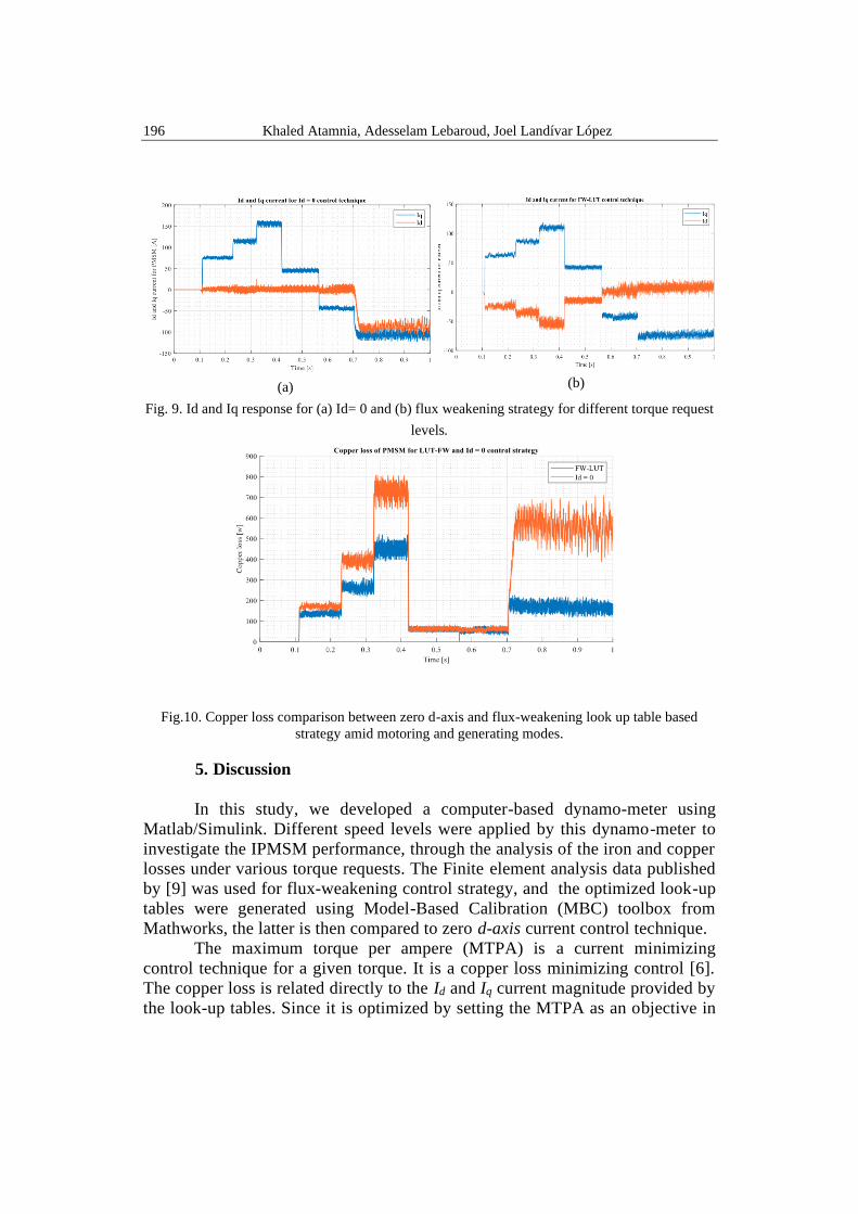
Id and Iq currents followed the exact current references generated by
look-up tables. It is worth mentioning that the Iq current for the control
technique (Id = 0) is much higher than the FW-LUT strategy. During motoring
mode, when we apply a positive torque, the Id current takes a negative value,
and positive values in generating mode (see Fig. 9).
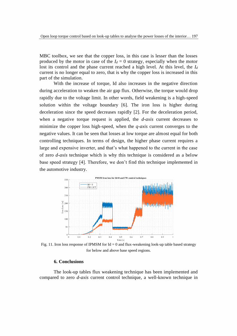
The iron and copper losses were compared for both control techniques in
Fig. 10. We notice that the loss is high for both strategies during high torque
requests, and also during the transition periods. Nonetheless, it tends to be
higher in the case of the Id equal zero control strategy. When a negative torque
request is applied at the high-speed region, the copper losses increase by a factor
of 3 compared to the FW-LUT. The iron loss (Fig. 11) is less than the copper
loss below base speed, especially in the FW-LUT control strategy. However,
The copper loss takes a large part of the total loss at the low-speed region,
despite the control technique, especially in the FW-LUT control technique.
196 Khaled Atamnia, Adesselam Lebaroud, Joel Landívar López
(a) (b)
Fig. 9. Id and Iq response for (a) Id= 0 and (b) flux weakening strategy for different torque request
levels.
Fig.10. Copper loss comparison between zero d-axis and flux-weakening look up table based
strategy amid motoring and generating modes.
5. Discussion
In this study, we developed a computer-based dynamo-meter using
Matlab/Simulink. Different speed levels were applied by this dynamo-meter to
investigate the IPMSM performance, through the analysis of the iron and copper
losses under various torque requests. The Finite element analysis data published
by [9] was used for flux-weakening control strategy, and the optimized look-up
tables were generated using Model-Based Calibration (MBC) toolbox from
Mathworks, the latter is then compared to zero d-axis current control technique.
The maximum torque per ampere (MTPA) is a current minimizing
control technique for a given torque. It is a copper loss minimizing control [6].
The copper loss is related directly to the Id and Iq current magnitude provided by
the look-up tables. Since it is optimized by setting the MTPA as an objective in
Open loop torque control based on look-up tables to analyse the power losses of the interior… 197
MBC toolbox, we see that the copper loss, in this case is lesser than the losses
produced by the motor in case of the Id = 0 strategy, especially when the motor
lost its control and the phase current reached a high level. At this level, the Id
current is no longer equal to zero, that is why the copper loss is increased in this
part of the simulation.
With the increase of torque, Id also increases in the negative direction
during acceleration to weaken the air gap flux. Otherwise, the torque would drop
rapidly due to the voltage limit. In other words, field weakening is a high-speed
solution within the voltage boundary [6]. The iron loss is higher during
deceleration since the speed decreases rapidly [2]. For the deceleration period,
when a negative torque request is applied, the d-axis current decreases to
minimize the copper loss high-speed, when the q-axis current converges to the
negative values. It can be seen that losses at low torque are almost equal for both
controlling techniques. In terms of design, the higher phase current requires a
large and expensive inverter, and that’s what happened to the current in the case
of zero d-axis technique which is why this technique is considered as a below
base speed strategy [4]. Therefore, we don’t find this technique implemented in
the automotive industry.
Fig. 11. Iron loss response of IPMSM for Id = 0 and flux-weakening look-up table based strategy
for below and above base speed regions.
6. Conclusions
The look-up tables flux weakening technique has been implemented and
compared to zero d-axis current control technique, a well-known technique in

198 Khaled Atamnia, Adesselam Lebaroud, Joel Landívar López
the industry application. In the first testing method, the simulation has shown
that the torque response followed the reference applied by the dynamo-meter at
different torque requests and speed regions when the other controller suffers at
high-speed demand. In terms of efficiency, the IPMSM copper loss for the flux
weakening strategy is less than in the zero Id controller, especially at high speed
when the motor losses its control. On the other hand, the iron loss is almost
equal for both techniques at the high-speed region, but it is not the case at low
speed, where the losses are higher in the case of zero d-axis current controller.
Reducing the losses of the IPMSM during motoring and generating
modes especially at high speeds, will help in increasing the vehicle performance
and extend its range. Therefore, the lookup table control technique could be an a
loss minimising or and optimisation solution to address this issue. The proposed
technique can be implemented in real-time to estimate the energy consumption
of the FPGA-based high-level electric vehicle model, which provides accurate
result during SIL, HIL and RCP testing.
R E F E R E N C E S
[1]. Lee, J.,Nam, K., Choi, S. and Kwon, S.: ‘A look-up table based loss minimizing control for
FCEV permanent magnet synchronous motors’. IEEE Vehicle Power and Propulsion
Conference, 2007, pp. 175–179.
[2]. Lee, J., Nam, K., Choi, S. and Kwon, S.: ‘Loss minimizing control of IPMSM with the use
of polynomial approximations’. IEEE Industry Applications Society Annual Meeting,
2008, pp. 1–9.
[3]. Peters, W., Wallscheid, O. and Böcker, J.: ‘A precise open-loop torque control for an
interior permanent magnet synchronous motor (IPMSM) considering iron losses’. IECON
2012-38th Annual Conference on IEEE Industrial Electronics Society, 2012, pp. 2877–
2882,
[4]. Monajemy, R.A.M.I.N. and Krishnan, R.: ‘Comparison of torque control strategies based on
the constant power loss control system for IPMSM’, Control in Power Electronics:
selected problems, 2002. pp.225–249.
[5]. Gallegos-Lopez, G., Gunawan, F.S. and Walters, J.E.: ‘Optimum torque control of
permanent-magnet AC machines in the field-weakened region’. IEEE Transactions on
Industry Applications, 41(4), 2005, pp.1020–1028.
[6]. Nam, Kwang Hee. ’AC motor control and electrical vehicle applications’( CRC press,
2018).
[7]. Hu, D. and Xu, L.: ‘Characterizing the torque look-up table of an IPM machine for
automotive application’, IEEE Conference and Expo Transportation Electrification
Asia-Pacific (ITEC Asia-Pacific), 2014, pp. 1-6.
[8]. Hu,D, https://www.mathworks.com/company/newsletters/articles/designing-a-torque-
controller-for-a-IPMSM-through-mulation-on-a-virtual-.html,accessed15 july 2020.
[9]. Dakai Hu (2020) Model File Package for Motor Control Design Public Video
https://www.mathworks.com/matlabcentral/fileexchange/72214-model-file-package-for-
motor-control-design-public-video, MATLAB Central File Exchange. Retrieved July 4,
2020.
[10]. Wang, Gaolin, Guoqiang Zhang, and Dianguo Xu.’ Position Sensorless Control
Techniques for Permanent Magnet Synchronous Machine Drives’. (Springer, 2020).