oper ator s manual 327pt5s - chainsaws, lawn …€¦ · contents english – 3 contents note the f...
TRANSCRIPT

327PT5S
Please read the operator’s manual carefully and make sure you understand the instructions
Operator′s manual
EEEEnnnngggglllliiiisssshhhh
before using the machine.
KEY
T
O SYMBOLS
SymbolsWARNING! The machine can be a dangerous tool if used incorrectly or carelessly, which can cause serious or fatal injury to the operator or others. It is extremely important that you read and understand the contents of the operator’s manual.
Please read the operator’s manual carefully and make sure you understand the instructions before using the machine.
Always wear:
• A protective helmet where there is a risk of falling objects
• Approved hearing protection
• Protective goggles or a visor
This product is in accordance with applicable EC directives.
This machine is not electrically insulated. If the machine touches or comes close to high-voltage power lines it could lead to death or serious bodily injury. Electricity can jump from one point to another by arcing. The higher the voltage, the greater the distance electricity can jump. Electricity can also travel through branches and other objects, especially if they are wet. Always keep a distance of at least 10 m between the machine and high-voltage power lines and/or any objects that are touching them. If have to work within this safe distance you should always contact the relevant power company to make sure the power is switched off before you start work.
This machine has a long reach. Make sure that no people or animals come closer than 15 m when the machine is running.
Always wear approved protective gloves.
Wear sturdy, non-slip boots.
Other symbols/decals on the machine refer to special certification requirements for certain markets.The engine is switched off by moving the stop switch to the stop position. CAUTION! The stop switch automatically returns to the start position. In order to prevent unintentional starting, the spark plug cap must be removed from the spark plug when assembling, checking and/or performing maintenance.
Always wear approved protective gloves.
Regular cleaning is required.
Visual check.
Protective goggles or a visor must be worn.
Filling with chain oil and adjusting oil flow
2 – English
CONTENTS
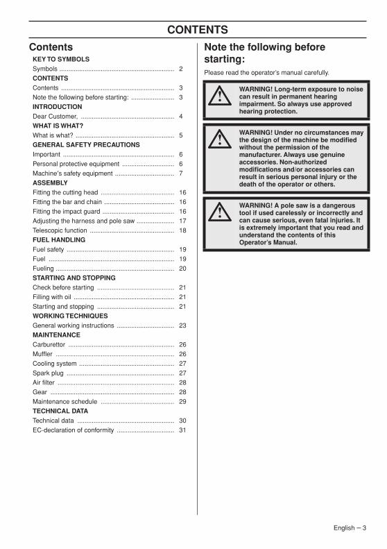
Contents Note the following before starting:Please read the operator’s manual carefully.
KEY TO SYMBOLSSymbols ................................................................ 2
CONTENTSContents ............................................................... 3
Note the following before starting: ........................ 3
INTRODUCTIONDear Customer, .................................................... 4
WHAT IS WHAT?What is what? ....................................................... 5
GENERAL SAFETY PRECAUTIONSImportant .............................................................. 6
Personal protective equipment ............................. 6
Machine′s safety equipment ................................. 7
ASSEMBLYFitting the cutting head ......................................... 16
Fitting the bar and chain ....................................... 16
Fitting the impact guard ........................................ 16
Adjusting the harness and pole saw ..................... 17
Telescopic function ............................................... 18
FUEL HANDLINGFuel safety ............................................................ 19
Fuel ...................................................................... 19
Fueling .................................................................. 20
STARTING AND STOPPINGCheck before starting ........................................... 21
Filling with oil ........................................................ 21
Starting and stopping ........................................... 21
WORKING TECHNIQUESGeneral working instructions ................................ 23
MAINTENANCECarburettor ........................................................... 26
Muffler .................................................................. 26
Cooling system ..................................................... 27
Spark plug ............................................................ 27
Air filter ................................................................. 28
Gear ..................................................................... 28
Maintenance schedule ......................................... 29
TECHNICAL DATATechnical data ...................................................... 30
EC-declaration of conformity ................................ 31
!WARNING! Long-term exposure to noise can result in permanent hearing impairment. So always use approved hearing protection.
!WARNING! Under no circumstances may the design of the machine be modified without the permission of the manufacturer. Always use genuine accessories. Non-authorized modifications and/or accessories can result in serious personal injury or the death of the operator or others.
!WARNING! A pole saw is a dangerous tool if used carelessly or incorrectly and can cause serious, even fatal injuries. It is extremely important that you read and understand the contents of this Operator’s Manual.
English – 3

INTR
ODUCTION
Dear Customer,Congratulations on your choice to buy a Husqvarna product! Husqvarna is based on a tradition that dates back to 1689, when the Swedish King Karl XI ordered the construction of a factory on the banks of the Husqvarna River, for production of muskets. The location was logical, since water power was harnessed from the Huskvarna River to create the water-powered plant. During the more than 300 years of beeing, the Husqvarna factory has produced a lot of different products, from wood stoves to modern kitchen appliances, sewing machines, bicycles, motorcycles etc. In 1956, the first motor driven lawn mowers appeared, followed by chain saws in 1959, and it is within this area Husqvarna is working today.
Today Husqvarna is one of the leading manufacturers in the world of forest and garden products, with quality as our highest priority. The business concept is to develop, manufacture and market motor driven products for forestry and gardening as well as for building and construction industry. Husqvarna′s aim is also to be in the front edge according to ergonomics, usability, security and environmental protection. That is the reason why we have developed many different features to provide our products within these areas.
We are convinced that you will appreciate with great satisfaction the quality and performance of our product for a very long time to come. The purchase of one of our products gives you access to professional help with repairs and service whenever this may be necessary. If the retailer who sells your machine is not one of our authorised dealers, ask for the address of your nearest service workshop.
It is our wish that you will be satisfied with your product and that it will be your companion for a long time. Think of this operator′s manual as a valuable document. By following its′ content (using, service, maintenance etc) the life span and the second-hand value of the machine can be extended. If you will sell this machine, make sure that the buyer will get the operator′s manual.
Thank you for using a Husqvarna product.
Husqvarna AB has a policy of continuous product development and therefore reserves the right to modify the design and appearance of products without prior notice.
4 – English

WHA
T IS
WHA
T?
What is what?
7 8
5
24
25
26
27
28
6
12
3
4 11
1213 11 14 15
16
1718
20
2223
9
10
19
21
29
1 Saw chain
2 Guide bar
3 Bar nut
4 Locking knob
5 Chain lubrication adjustment screw
6 Filling with chain oil
7 Chain oil tank
8 Chain tensioning screw
9 Shaft
10 Front handle
11 Harness support hook
12 Stop switch
13 Throttle lockout
14 Spark plug cap and spark plug
15 Cylinder cover
16 Starter handle
17 Impact guard (only some models)
18 Fuel tank
19 Air filter cover
20 Air purge.
21 Choke control
22 Throttle trigger
23 Throttle/hand guard
24 Operator′s manual
25 Harness
26 Transport guard, bar
27 Combination spanner
28 Allen key
29 Torx wrench
English – 5
GENERAL SAFETY PRECA
UTIONS
Important Personal protective equipment
PROTECTIVE HELMET AND VISOR
Protective helmet must be used.
HEARING PROTECTION
Wear hearing protection that provides adequate noise reduction.
EYE PROTECTION
Protective goggles or a visor must be worn.
GLOVES
Gloves should be worn when necessary, e.g., when fitting cutting attachments.
BOOTS
Wear sturdy, non-slip boots.
IMPORTANT!
The machine is only designed for cutting branches and twigs.
Never use a machine that has been modified in any way from its original specification.
Never use the machine if you are tired, if you have drunk alcohol, or if you are taking medication that could affect your vision, your judgement or your co-ordination.
Wear personal protective equipment. See instructions under the heading ”Personal protective equipment”.
Never use the machine in extreme weather conditions such as severe cold, very hot and/or humid climates.
Never use a machine that is faulty. Carry out the checks, maintenance and service instructions described in this manual. Some maintenance and service measures must be carried out by trained and qualified specialists. See instructions under the heading Maintenance.
All covers and guards must be fitted before starting. Ensure that the spark plug cap and ignition lead are undamaged to avoid the risk of electric shock.
!WARNING! This machine produces an electromagnetic field during operation. This field may under some circumstances interfere with active or passive medical implants. To reduce the risk of serious or fatal injury, we recommend persons with medical implants to consult their physician and the medical implant manufacturer before operating this machine.
!WARNING! Running an engine in a confined or badly ventilated area can result in death due to asphyxiation or carbon monoxide poisoning.
!WARNING! Never allow children to use or be in the vicinity of the machine. As the machine is equipped with a spring-loaded stop switch and can be started by low speed and force on the starter handle, even small children under some circumstances can produce the force necessary to start the machine. This can mean a risk of serious personal injury. Therefore remove the spark plug cap when the machine is not under close supervision.
IMPORTANT!
A pole saw is a dangerous tool if used carelessly or incorrectly and can cause serious, even fatal injuries. It is extremely important that you read and understand the contents of this Operator’s Manual.
You must use approved personal protective equipment whenever you use the machine. Personal protective equipment cannot eliminate the risk of injury but it will reduce the degree of injury if an accident does happen. Ask your dealer for help in choosing the right equipment.
!WARNING! Listen out for warning signals or shouts when you are wearing hearing protection. Always remove your hearing protection as soon as the engine stops.
6 – English
GENERAL SAFETY PRECA
UTIONS
CLOTHING
Wear clothes made of a strong fabric and avoid loose clothing that can catch on twigs and branches. Always wear heavy, long pants. Do not wear jewellery, shorts sandals or go barefoot. Secure hair so it is above shoulder level.
FIRST AID KIT
Always have a first aid kit nearby.
Machine′s safety equipmentThis section describes the machine′s safety equipment, its purpose, and how checks and maintenance should be carried out to ensure that it operates correctly. See the ”What is what?” section to locate where this equipment is positioned on your machine.
The life span of the machine can be reduced and the risk of accidents can increase if machine maintenance is not carried out correctly and if service and/or repairs are not carried out professionally. If you need further information please contact your nearest service workshop.
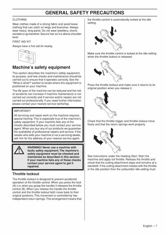
Throttle lockoutThe throttle lockout is designed to prevent accidental operation of the throttle control. When you press the lock (A) (i.e. when you grasp the handle) it releases the throttle control (B). When you release the handle the throttle control and the throttle lockout both move back to their original positions. This movement is controlled by two independent return springs. This arrangement means that
the throttle control is automatically locked at the idle setting.
Make sure the throttle control is locked at the idle setting when the throttle lockout is released.
Press the throttle lockout and make sure it returns to its original position when you release it.
Check that the throttle trigger and throttle lockout move freely and that the return springs work properly.
See instructions under the heading Start. Start the machine and apply full throttle. Release the throttle and check that the cutting attachment stops and remains at a standstill. If the cutting attachment rotates with the throttle in the idle position then the carburettor idle setting must
IMPORTANT!
All servicing and repair work on the machine requires special training. This is especially true of the machine′s safety equipment. If your machine fails any of the checks described below you must contact your service agent. When you buy any of our products we guarantee the availability of professional repairs and service. If the retailer who sells your machine is not a servicing dealer, ask him for the address of your nearest service agent.
!WARNING! Never use a machine with faulty safety equipment. The machine’s safety equipment must be checked and maintained as described in this section. If your machine fails any of these checks contact your service agent to get it repaired.
A
B
English – 7
GENERAL SAFETY PRECA
UTIONS
8 – English
be checked. See instructions under the heading Maintenance.
Stop switchUse the stop switch to switch off the engine.
Start the engine and make sure the engine stops when you move the stop switch to the stop setting.
Vibration damping system
Your machine is equipped with a vibration damping system that is designed to minimize vibration and make operation easier.
The machine′s vibration damping system reduces the transfer of vibration between the engine unit/cutting equipment and the machine′s handle unit.
Regularly check the vibration damping units for cracks or deformation. Check that the vibration damping element is undamaged and securely attached.
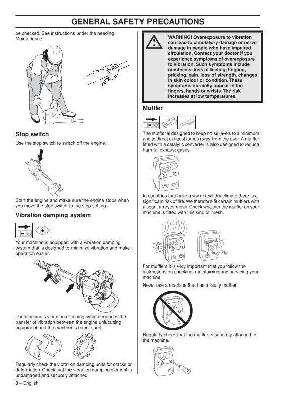
Muffler
The muffler is designed to keep noise levels to a minimum and to direct exhaust fumes away from the user. A muffler fitted with a catalytic converter is also designed to reduce harmful exhaust gases.
In countries that have a warm and dry climate there is a significant risk of fire. We therefore fit certain mufflers with a spark arrestor mesh. Check whether the muffler on your machine is fitted with this kind of mesh.
For mufflers it is very important that you follow the instructions on checking, maintaining and servicing your machine.
Never use a machine that has a faulty muffler.
Regularly check that the muffler is securely attached to the machine.
!WARNING! Overexposure to vibration can lead to circulatory damage or nerve damage in people who have impaired circulation. Contact your doctor if you experience symptoms of overexposure to vibration. Such symptoms include numbness, loss of feeling, tingling, pricking, pain, loss of strength, changes in skin colour or condition. These symptoms normally appear in the fingers, hands or wrists. The risk increases at low temperatures.
GENERAL SAFETY PRECAUTIONS
English – 9
If the muffler on your machine is fitted with a spark arrestor mesh this must be cleaned regularly. A blocked mesh will cause the engine to overheat and may lead to serious damage.
HarnessCheck that the harness is not damaged.
In an emergency situation, release yourself from machine and harness according to the following method.
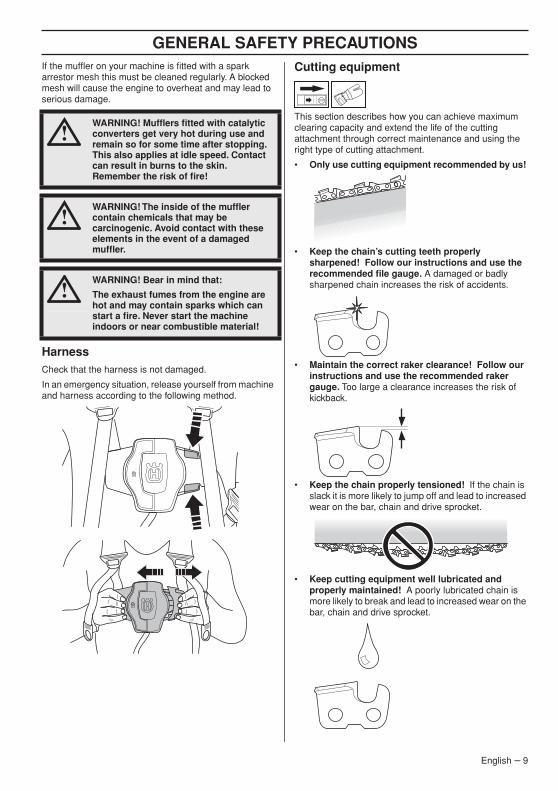
Cutting equipment
This section describes how you can achieve maximum clearing capacity and extend the life of the cutting attachment through correct maintenance and using the right type of cutting attachment.
• Only use cutting equipment recommended by us!
• Keep the chain’s cutting teeth properly sharpened! Follow our instructions and use the recommended file gauge. A damaged or badly sharpened chain increases the risk of accidents.
• Maintain the correct raker clearance! Follow our instructions and use the recommended raker gauge. Too large a clearance increases the risk of kickback.
• Keep the chain properly tensioned! If the chain is slack it is more likely to jump off and lead to increased wear on the bar, chain and drive sprocket.
• Keep cutting equipment well lubricated and properly maintained! A poorly lubricated chain is more likely to break and lead to increased wear on the bar, chain and drive sprocket.
!WARNING! Mufflers fitted with catalytic converters get very hot during use and remain so for some time after stopping. This also applies at idle speed. Contact can result in burns to the skin. Remember the risk of fire!
!WARNING! The inside of the muffler contain chemicals that may be carcinogenic. Avoid contact with these elements in the event of a damaged muffler.
!WARNING! Bear in mind that:
The exhaust fumes from the engine are hot and may contain sparks which can start a fire. Never start the machine indoors or near combustible material!
GENERAL SAFETY PRECAUTIONS
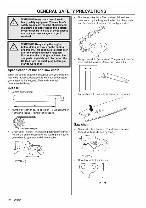
Specification of bar and saw chainWhen the cutting attachment supplied with your machine has to be replaced, because it is worn out or damaged, you must only fit the types of bar and saw chain recommended by us.
Guide bar
• Length (inches/cm)
• Number of teeth on bar tip sprocket (T). Small number = small tip radius = low risk of kickback.
• Chain pitch (inches). The spacing between the drive links of the chain must match the spacing of the teeth on the bar tip sprocket and drive sprocket.
• Number of drive links. The number of drive links is determined by the length of the bar, the chain pitch and the number of teeth on the bar tip sprocket.
• Bar groove width (inches/mm). The groove in the bar must match the width of the chain drive links.
• Lubrication hole and hole for the chain tensioner.
Saw chain• Saw chain pitch (inches). (The distance between
three drive links, divided by two.)
• Drive link width (mm/inches)
!WARNING! Never use a machine with faulty safety equipment. The machine’s safety equipment must be checked and maintained as described in this section. If your machine fails any of these checks contact your service agent to get it repaired.
!WARNING! Always stop the engine before doing any work on the cutting attachment. This continues to rotate even after the throttle has been released. Ensure that the cutting attachment has stopped completely and disconnect the HT lead from the spark plug before you start to work on it.
10 – English
GENERAL SAFETY PRECAUTIONS
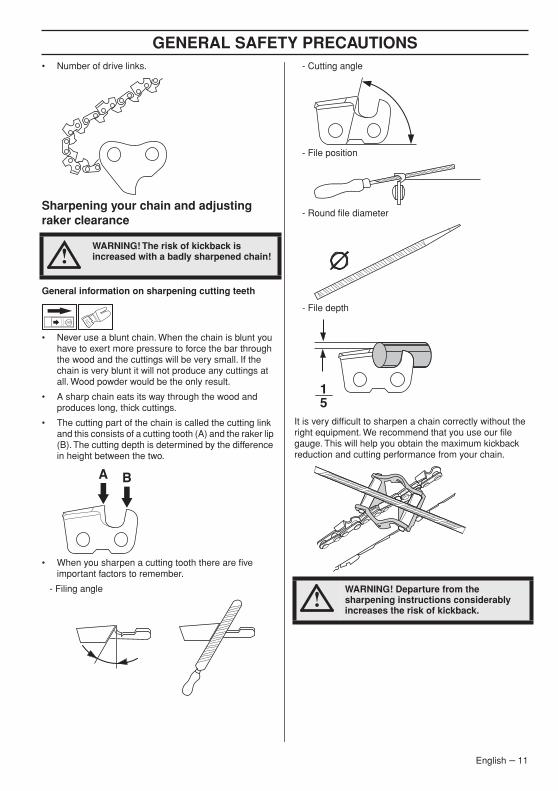
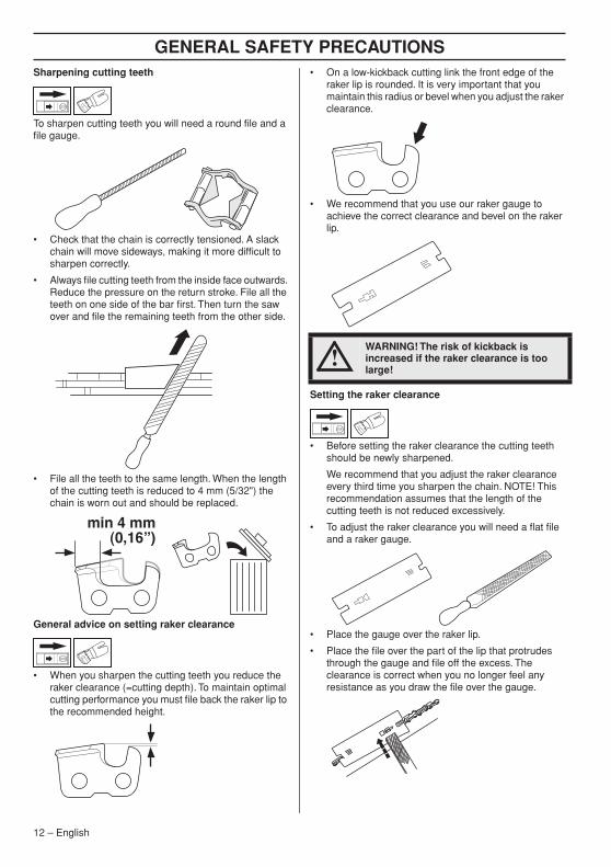
• Number of drive links.Sharpening your chain and adjusting raker clearance
General information on sharpening cutting teeth
• Never use a blunt chain. When the chain is blunt you have to exert more pressure to force the bar through the wood and the cuttings will be very small. If the chain is very blunt it will not produce any cuttings at all. Wood powder would be the only result.
• A sharp chain eats its way through the wood and produces long, thick cuttings.
• The cutting part of the chain is called the cutting link and this consists of a cutting tooth (A) and the raker lip (B). The cutting depth is determined by the difference in height between the two.
• When you sharpen a cutting tooth there are five important factors to remember.
- Filing angle
- Cutting angle
- File position
- Round file diameter
- File depth
It is very difficult to sharpen a chain correctly without the right equipment. We recommend that you use our file gauge. This will help you obtain the maximum kickback reduction and cutting performance from your chain.
!WARNING! The risk of kickback is increased with a badly sharpened chain!
A B
!WARNING! Departure from the sharpening instructions considerably increases the risk of kickback.
15
English – 11
GENERAL SAFETY PRECAUTIONS
Sharpening cutting teethTo sharpen cutting teeth you will need a round file and a file gauge.
• Check that the chain is correctly tensioned. A slack chain will move sideways, making it more difficult to sharpen correctly.
• Always file cutting teeth from the inside face outwards. Reduce the pressure on the return stroke. File all the teeth on one side of the bar first. Then turn the saw over and file the remaining teeth from the other side.
• File all the teeth to the same length. When the length of the cutting teeth is reduced to 4 mm (5/32") the chain is worn out and should be replaced.
General advice on setting raker clearance
• When you sharpen the cutting teeth you reduce the raker clearance (=cutting depth). To maintain optimal cutting performance you must file back the raker lip to the recommended height.
• On a low-kickback cutting link the front edge of the raker lip is rounded. It is very important that you maintain this radius or bevel when you adjust the raker clearance.
• We recommend that you use our raker gauge to achieve the correct clearance and bevel on the raker lip.
Setting the raker clearance
• Before setting the raker clearance the cutting teeth should be newly sharpened.
We recommend that you adjust the raker clearance every third time you sharpen the chain. NOTE! This recommendation assumes that the length of the cutting teeth is not reduced excessively.
• To adjust the raker clearance you will need a flat file and a raker gauge.
• Place the gauge over the raker lip.
• Place the file over the part of the lip that protrudes through the gauge and file off the excess. The clearance is correct when you no longer feel any resistance as you draw the file over the gauge.
min 4 mm(0,16”)
!WARNING! The risk of kickback is increased if the raker clearance is too large!
12 – English
GENERAL SAFETY PRECAUTIONS
Tensioning the chain• The more you use a chain the longer it becomes. It is therefore important to adjust the chain regularly to take up the slack.
• Check the chain tension every time you refuel. NOTE! A new chain has a running-in period during which you should check the tension more frequently.
• Tension the chain as tightly as possible, but not so tight that you cannot pull it round freely by hand.
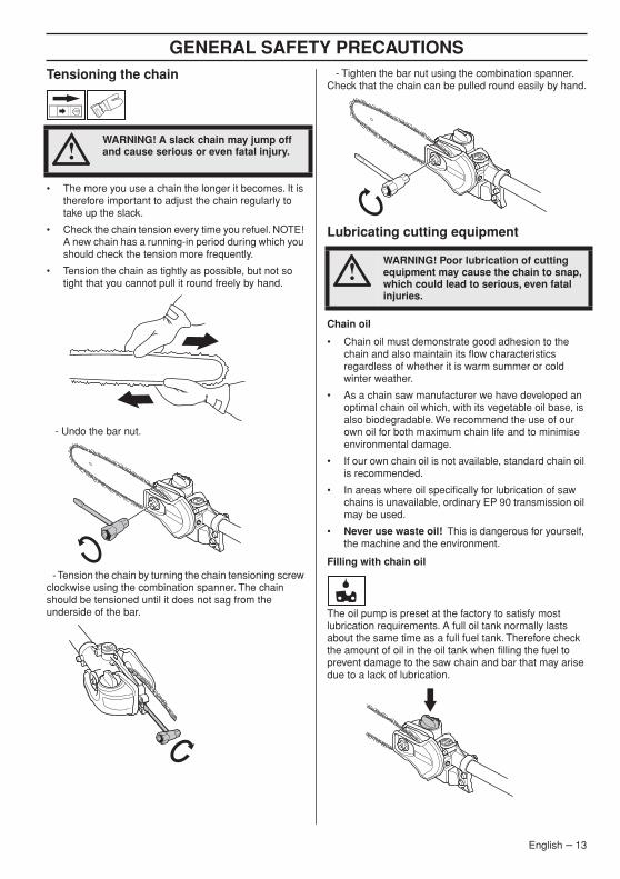
- Undo the bar nut.
- Tension the chain by turning the chain tensioning screw clockwise using the combination spanner. The chain should be tensioned until it does not sag from the underside of the bar.
- Tighten the bar nut using the combination spanner. Check that the chain can be pulled round easily by hand.
Lubricating cutting equipment
Chain oil
• Chain oil must demonstrate good adhesion to the chain and also maintain its flow characteristics regardless of whether it is warm summer or cold winter weather.
• As a chain saw manufacturer we have developed an optimal chain oil which, with its vegetable oil base, is also biodegradable. We recommend the use of our own oil for both maximum chain life and to minimise environmental damage.
• If our own chain oil is not available, standard chain oil is recommended.
• In areas where oil specifically for lubrication of saw chains is unavailable, ordinary EP 90 transmission oil may be used.
• Never use waste oil! This is dangerous for yourself, the machine and the environment.
Filling with chain oil
The oil pump is preset at the factory to satisfy most lubrication requirements. A full oil tank normally lasts about the same time as a full fuel tank. Therefore check the amount of oil in the oil tank when filling the fuel to prevent damage to the saw chain and bar that may arise due to a lack of lubrication.
!WARNING! A slack chain may jump off and cause serious or even fatal injury.
!WARNING! Poor lubrication of cutting equipment may cause the chain to snap, which could lead to serious, even fatal injuries.
English – 13
GENERAL SAFETY PRECAUTIONS
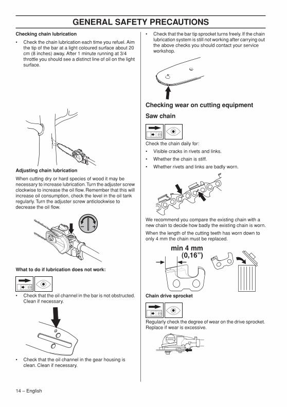
Checking chain lubrication• Check the chain lubrication each time you refuel. Aim the tip of the bar at a light coloured surface about 20 cm (8 inches) away. After 1 minute running at 3/4 throttle you should see a distinct line of oil on the light surface.
Adjusting chain lubrication
When cutting dry or hard species of wood it may be necessary to increase lubrication. Turn the adjuster screw clockwise to increase the oil flow. Remember that this will increase oil consumption, check the level in the oil tank regularly. Turn the adjuster screw anticlockwise to decrease the oil flow.
What to do if lubrication does not work:
• Check that the oil channel in the bar is not obstructed. Clean if necessary.
• Check that the oil channel in the gear housing is clean. Clean if necessary.
• Check that the bar tip sprocket turns freely. If the chain lubrication system is still not working after carrying out the above checks you should contact your service workshop.
Checking wear on cutting equipment
Saw chain
Check the chain daily for:
• Visible cracks in rivets and links.
• Whether the chain is stiff.
• Whether rivets and links are badly worn.
We recommend you compare the existing chain with a new chain to decide how badly the existing chain is worn.
When the length of the cutting teeth has worn down to only 4 mm the chain must be replaced.
Chain drive sprocket
Regularly check the degree of wear on the drive sprocket. Replace if wear is excessive.
min 4 mm(0,16”)
14 – English
GENERAL SAFETY PRECAUTIONS
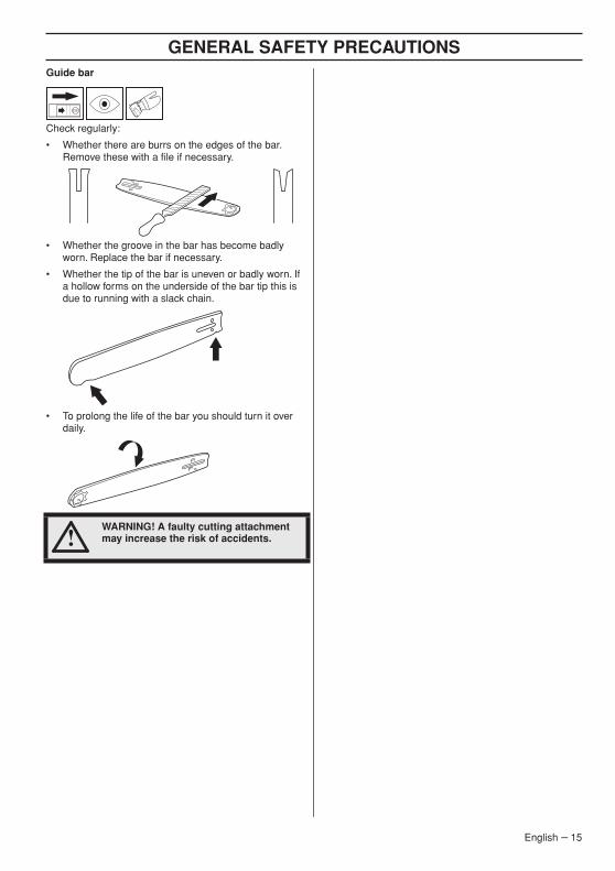
Guide barCheck regularly:
• Whether there are burrs on the edges of the bar. Remove these with a file if necessary.
• Whether the groove in the bar has become badly worn. Replace the bar if necessary.
• Whether the tip of the bar is uneven or badly worn. If a hollow forms on the underside of the bar tip this is due to running with a slack chain.
• To prolong the life of the bar you should turn it over daily.
!WARNING! A faulty cutting attachment may increase the risk of accidents.
English – 15
ASSEMBLY
Fitting the cutting head
• Fit the cutting head on the shaft so that the screw (A) is aligned with the hole in the shaft as shown.
• Tighten screw A.
• Tighten screw B.
CAUTION! Make sure that the drive shaft inside the shaft engages with the cut-out in the cutting head.
Fitting the bar and chain
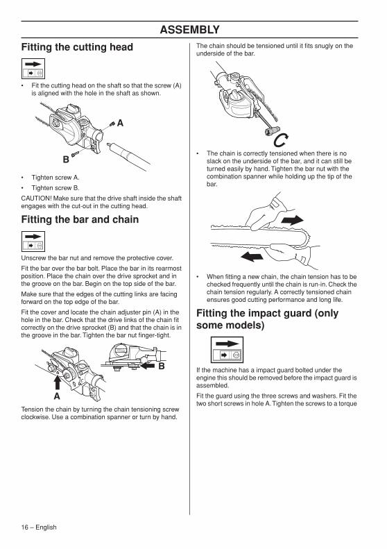
Unscrew the bar nut and remove the protective cover.
Fit the bar over the bar bolt. Place the bar in its rearmost position. Place the chain over the drive sprocket and in the groove on the bar. Begin on the top side of the bar.
Make sure that the edges of the cutting links are facing forward on the top edge of the bar.
Fit the cover and locate the chain adjuster pin (A) in the hole in the bar. Check that the drive links of the chain fit correctly on the drive sprocket (B) and that the chain is in the groove in the bar. Tighten the bar nut finger-tight.
Tension the chain by turning the chain tensioning screw clockwise. Use a combination spanner or turn by hand.
The chain should be tensioned until it fits snugly on the underside of the bar.
• The chain is correctly tensioned when there is no slack on the underside of the bar, and it can still be turned easily by hand. Tighten the bar nut with the combination spanner while holding up the tip of the bar.
• When fitting a new chain, the chain tension has to be checked frequently until the chain is run-in. Check the chain tension regularly. A correctly tensioned chain ensures good cutting performance and long life.
Fitting the impact guard (only some models)
If the machine has a impact guard bolted under the engine this should be removed before the impact guard is assembled.
Fit the guard using the three screws and washers. Fit the two short screws in hole A. Tighten the screws to a torque
A
B
A
B
16 – English
ASSEMBLY
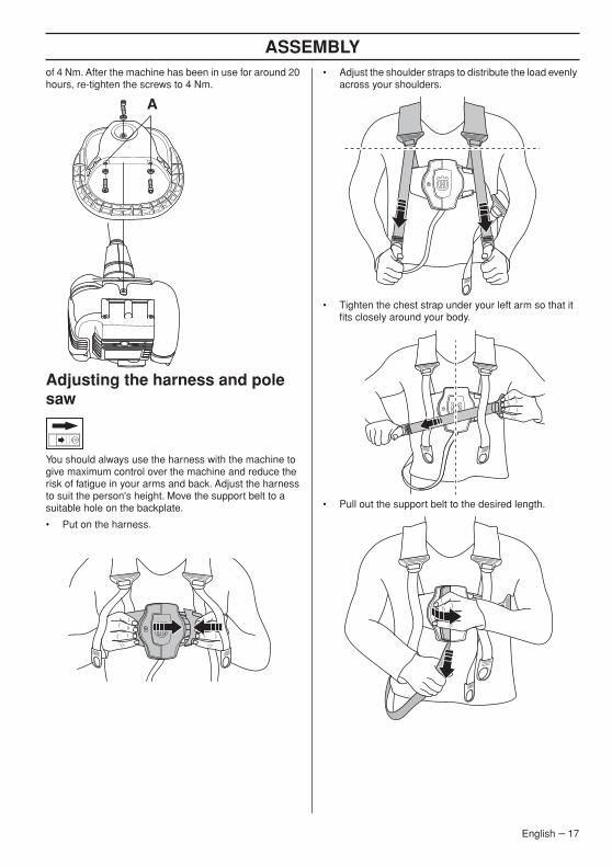
of 4 Nm. After the machine has been in use for around 20 hours, re-tighten the screws to 4 Nm.Adjusting the harness and pole saw
You should always use the harness with the machine to give maximum control over the machine and reduce the risk of fatigue in your arms and back. Adjust the harness to suit the person's height. Move the support belt to a suitable hole on the backplate.
• Put on the harness.
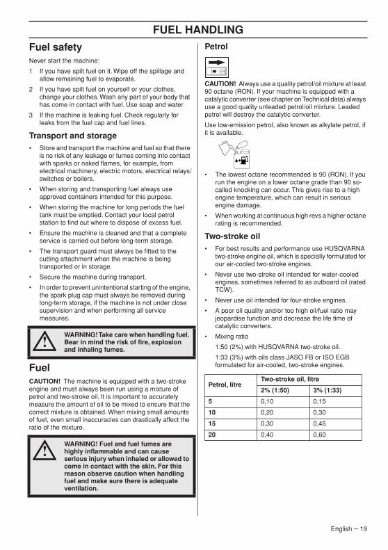
• Adjust the shoulder straps to distribute the load evenly across your shoulders.
• Tighten the chest strap under your left arm so that it fits closely around your body.
• Pull out the support belt to the desired length.
A
English – 17

ASSEMBLY
• Slide the support belt into the machine's supporthooks and lock the support belt according to the picture.
• Adjust the support belt's length exactly for a comfortable working position.
Telescopic function
The shaft of the machine is telescopic. To change the length of the shaft, do the following:
• Undo the knob.
• Pull out the shaft to the desired length.
• Tighten the knob.
18 – English
FUEL HANDLING
Fuel safetyNever start the machine:
1 If you have spilt fuel on it. Wipe off the spillage and allow remaining fuel to evaporate.
2 If you have spilt fuel on yourself or your clothes, change your clothes. Wash any part of your body that has come in contact with fuel. Use soap and water.
3 If the machine is leaking fuel. Check regularly for leaks from the fuel cap and fuel lines.
Transport and storage• Store and transport the machine and fuel so that there
is no risk of any leakage or fumes coming into contact with sparks or naked flames, for example, from electrical machinery, electric motors, electrical relays/switches or boilers.
• When storing and transporting fuel always use approved containers intended for this purpose.
• When storing the machine for long periods the fuel tank must be emptied. Contact your local petrol station to find out where to dispose of excess fuel.
• Ensure the machine is cleaned and that a complete service is carried out before long-term storage.
• The transport guard must always be fitted to the cutting attachment when the machine is being transported or in storage.
• Secure the machine during transport.
• In order to prevent unintentional starting of the engine, the spark plug cap must always be removed during long-term storage, if the machine is not under close supervision and when performing all service measures.
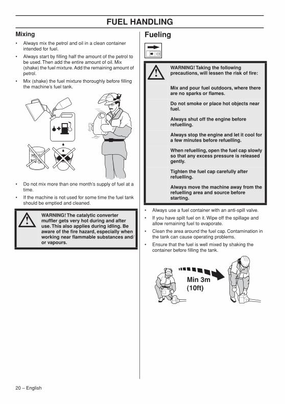
FuelCAUTION! The machine is equipped with a two-stroke engine and must always been run using a mixture of petrol and two-stroke oil. It is important to accurately measure the amount of oil to be mixed to ensure that the correct mixture is obtained. When mixing small amounts of fuel, even small inaccuracies can drastically affect the ratio of the mixture.
Petrol
CAUTION! Always use a quality petrol/oil mixture at least 90 octane (RON). If your machine is equipped with a catalytic converter (see chapter on Technical data) always use a good quality unleaded petrol/oil mixture. Leaded petrol will destroy the catalytic converter.
Use low-emission petrol, also known as alkylate petrol, if it is available.
• The lowest octane recommended is 90 (RON). If you run the engine on a lower octane grade than 90 so-called knocking can occur. This gives rise to a high engine temperature, which can result in serious engine damage.
• When working at continuous high revs a higher octane rating is recommended.
Two-stroke oil• For best results and performance use HUSQVARNA
two-stroke engine oil, which is specially formulated for our air-cooled two-stroke engines.
• Never use two-stroke oil intended for water-cooled engines, sometimes referred to as outboard oil (rated TCW).
• Never use oil intended for four-stroke engines.
• A poor oil quality and/or too high oil/fuel ratio may jeopardise function and decrease the life time of catalytic converters.
• Mixing ratio
1:50 (2%) with HUSQVARNA two-stroke oil.
1:33 (3%) with oils class JASO FB or ISO EGB formulated for air-cooled, two-stroke engines.
!WARNING! Take care when handling fuel. Bear in mind the risk of fire, explosion and inhaling fumes.
!WARNING! Fuel and fuel fumes are highly inflammable and can cause serious injury when inhaled or allowed to come in contact with the skin. For this reason observe caution when handling fuel and make sure there is adequate ventilation.
Petrol, litreTwo-stroke oil, litre
2% (1:50) 3% (1:33)
5 0,10 0,15
10 0,20 0,30
15 0,30 0,45
20 0,40 0,60
English – 19
FUEL HANDLING
Mixing• Always mix the petrol and oil in a clean containerintended for fuel.
• Always start by filling half the amount of the petrol to be used. Then add the entire amount of oil. Mix (shake) the fuel mixture. Add the remaining amount of petrol.
• Mix (shake) the fuel mixture thoroughly before filling the machine’s fuel tank.
• Do not mix more than one month’s supply of fuel at a time.
• If the machine is not used for some time the fuel tank should be emptied and cleaned.
Fueling
• Always use a fuel container with an anti-spill valve.
• If you have spilt fuel on it. Wipe off the spillage and allow remaining fuel to evaporate.
• Clean the area around the fuel cap. Contamination in the tank can cause operating problems.
• Ensure that the fuel is well mixed by shaking the container before filling the tank.
!WARNING! The catalytic converter muffler gets very hot during and after use. This also applies during idling. Be aware of the fire hazard, especially when working near flammable substances and/or vapours.
!WARNING! Taking the following precautions, will lessen the risk of fire:
Mix and pour fuel outdoors, where there are no sparks or flames.
Do not smoke or place hot objects near fuel.
Always shut off the engine before refuelling.
Always stop the engine and let it cool for a few minutes before refuelling.
When refuelling, open the fuel cap slowly so that any excess pressure is released gently.
Tighten the fuel cap carefully after refuelling.
Always move the machine away from the refuelling area and source before starting.
20 – English
STARTING AND STOPPING
Check before starting
• Inspect the working area. Remove any objects that could be thrown out.
• Check the cutting attachment. Never use blunt, cracked or damaged equipment.
• Check that the machine is in perfect working order. Check that all nuts and screws are tight.
• Make sure the chain is adequately lubricated.
• Check that the cutting attachment always stops when the engine is idling.
• Only use the machine for the purpose it was intended for.
• Make sure that the handle and safety features are in good working order. Never use a machine that lacks a part or has been modified outside its specifications.
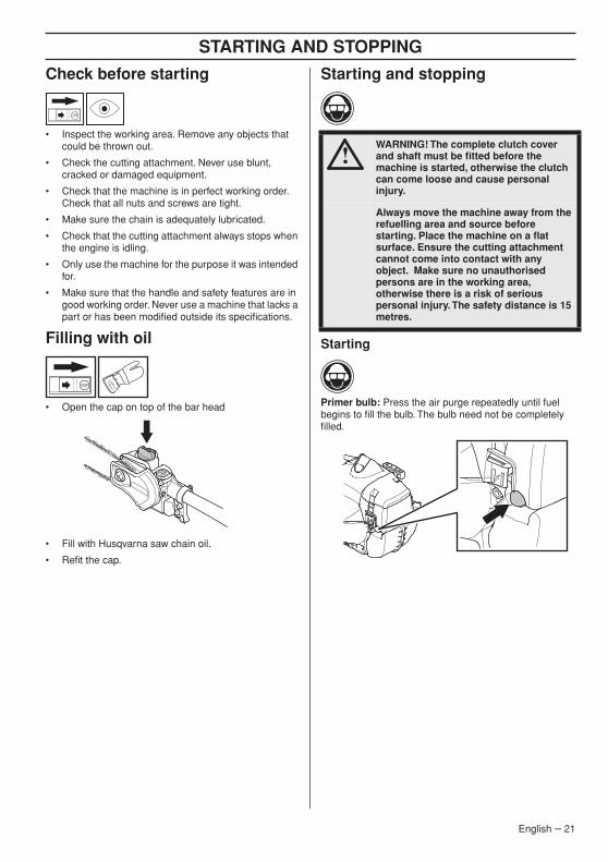
Filling with oil
• Open the cap on top of the bar head
• Fill with Husqvarna saw chain oil.
• Refit the cap.
Starting and stopping
Starting
Primer bulb: Press the air purge repeatedly until fuel begins to fill the bulb. The bulb need not be completely filled.
!WARNING! The complete clutch cover and shaft must be fitted before the machine is started, otherwise the clutch can come loose and cause personal injury.
Always move the machine away from the refuelling area and source before starting. Place the machine on a flat surface. Ensure the cutting attachment cannot come into contact with any object. Make sure no unauthorised persons are in the working area, otherwise there is a risk of serious personal injury. The safety distance is 15 metres.
English – 21
STARTING AND STOPPING
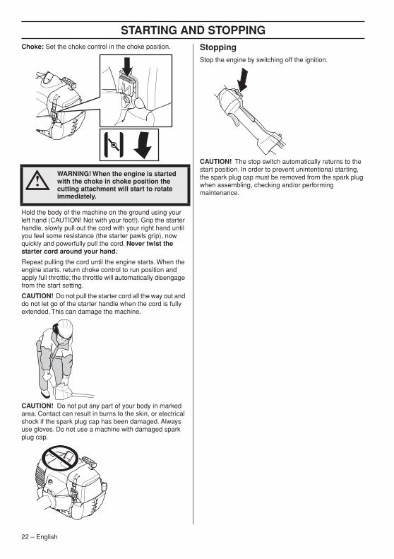
Choke: Set the choke control in the choke position.Hold the body of the machine on the ground using your left hand (CAUTION! Not with your foot!). Grip the starter handle, slowly pull out the cord with your right hand until you feel some resistance (the starter pawls grip), now quickly and powerfully pull the cord. Never twist the starter cord around your hand.
Repeat pulling the cord until the engine starts. When the engine starts. return choke control to run position and apply full throttle; the throttle will automatically disengage from the start setting.
CAUTION! Do not pull the starter cord all the way out and do not let go of the starter handle when the cord is fully extended. This can damage the machine.
CAUTION! Do not put any part of your body in marked area. Contact can result in burns to the skin, or electrical shock if the spark plug cap has been damaged. Always use gloves. Do not use a machine with damaged spark plug cap.
StoppingStop the engine by switching off the ignition.
CAUTION! The stop switch automatically returns to the start position. In order to prevent unintentional starting, the spark plug cap must be removed from the spark plug when assembling, checking and/or performing maintenance.
!WARNING! When the engine is started with the choke in choke position the cutting attachment will start to rotate immediately.
22 – English
WORKING TECHNIQUES
General working instructions
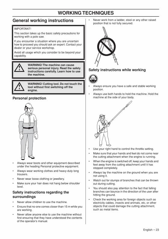
Personal protection
• Always wear boots and other equipment described under the heading Personal protective equipment.
• Always wear working clothes and heavy-duty long trousers.
• Never wear loose clothing or jewellery.
• Make sure your hair does not hang below shoulder level.
Safety instructions regarding the surroundings• Never allow children to use the machine.
• Ensure that no-one comes closer than 15 m while you are working.
• Never allow anyone else to use the machine without first ensuring that they have understood the contents of the operator’s manual.
• Never work from a ladder, stool or any other raised position that is not fully secured.
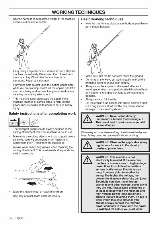
Safety instructions while working
• Always ensure you have a safe and stable working position.
• Always use both hands to hold the machine. Hold the machine at the side of your body.
• Use your right hand to control the throttle setting.
• Make sure that your hands and feet do not come near the cutting attachment when the engine is running.
• When the engine is switched off, keep your hands and feet away from the cutting attachment until it has stopped completely.
• Always lay the machine on the ground when you are not using it.
• Watch out for stumps of branches that can be thrown out during cutting.
• You should also pay attention to the fact that falling branches can bounce in the direction of the user after hitting the ground.
• Check the working area for foreign objects such as electricity cables, insects and animals, etc, or other objects that could damage the cutting attachment, such as metal items.
IMPORTANT!
This section takes up the basic safety precautions for working with a pole saw.
If you encounter a situation where you are uncertain how to proceed you should ask an expert. Contact your dealer or your service workshop.
Avoid all usage which you consider to be beyond your capability.
!WARNING! The machine can cause serious personal injury. Read the safety instructions carefully. Learn how to use the machine.
!WARNING! Cutting tool. Do not touch the tool without first switching off the engine.
English – 23
WORKING TECHNIQUES
• Use the harness to support the weight of the machineand make it easier to handle.
• If any foreign object is hit or if vibrations occur stop the machine immediately. Disconnect the HT lead from the spark plug. Check that the machine is not damaged. Repair any damage.
• If anything gets caught up in the cutting attachment while you are working, switch off the engine and let it stop completely and remove the ignition lead before cleaning the cutting attachment.
• This machine is not electrically insulated. If the machine touches or comes close to high-voltage power lines it could lead to death or serious bodily injury.
Safety instructions after completing work
• The transport guard should always be fitted to the cutting attachment when the machine is not in use.
• Make sure the cutting attachment has stopped before cleaning, carrying out repairs or an inspection. Disconnect the HT lead from the spark plug.
• Always wear heavy-duty gloves when repairing the cutting attachment. This is extremely sharp and can easily cause cuts.
• Store the machine out of reach of children.
• Use only original spare parts for repairs.
Basic working techniques• Hold the machine as close to your body as possible to
get the best balance.
• Make sure that the tip does not touch the ground.• Do not rush the work, but work steadily until all the
branches have been cut back cleanly.• Always slow the engine to idle speed after each
working operation. Long periods at full throttle without any load on the engine can lead to serious engine damage.
• Always work at full throttle.• Let the engine drop back to idle speed between each
cut. Long periods at full throttle can cause serious damage to the centrifugal clutch.
Observe great care when working close to overhead power lines. Falling branches can result in short-circuiting.
!WARNING! Never stand directly underneath a branch that is being cut. This could lead to serious or even fatal personal injury.
!WARNING! Observe the applicable safety regulations for work in the vicinity of overhead power lines.
!WARNING! This machine is not electrically insulated. If the machine touches or comes close to high-voltage power lines it could lead to death or serious bodily injury. Electricity can jump from one point to another by arcing. The higher the voltage, the greater the distance electricity can jump. Electricity can also travel through branches and other objects, especially if they are wet. Always keep a distance of at least 10 m between the machine and high-voltage power lines and/or any objects that are touching them. If have to work within this safe distance you should always contact the relevant power company to make sure the power is switched off before you start work.
24 – English
WORKING TECHNIQUES
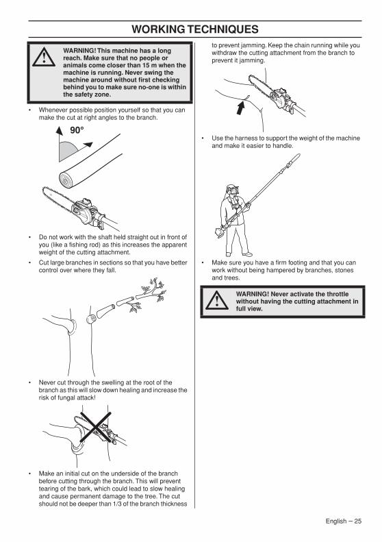
• Whenever possible position yourself so that you can make the cut at right angles to the branch.
• Do not work with the shaft held straight out in front of you (like a fishing rod) as this increases the apparent weight of the cutting attachment.
• Cut large branches in sections so that you have better control over where they fall.
• Never cut through the swelling at the root of the branch as this will slow down healing and increase the risk of fungal attack!
• Make an initial cut on the underside of the branch before cutting through the branch. This will prevent tearing of the bark, which could lead to slow healing and cause permanent damage to the tree. The cut should not be deeper than 1/3 of the branch thickness
to prevent jamming. Keep the chain running while you withdraw the cutting attachment from the branch to prevent it jamming.
• Use the harness to support the weight of the machine and make it easier to handle.
• Make sure you have a firm footing and that you can work without being hampered by branches, stones and trees.
!WARNING! This machine has a long reach. Make sure that no people or animals come closer than 15 m when the machine is running. Never swing the machine around without first checking behind you to make sure no-one is within the safety zone.
90°
!WARNING! Never activate the throttle without having the cutting attachment in full view.
English – 25
MAINTENANCE
26 – English
CarburettorYour Husqvarna product has been designed and manufactured to specifications that reduce harmful emissions. After the engine has used 8-10 tanks of fuel the engine will be run-in. To ensure that it continues to run at peak performance and to minimise harmful exhaust emissions after the running-in period, ask your dealer/service workshop (who will have a rev counter at their disposal) to adjust your carburettor.
Function
• The carburettor governs the engine’s speed via the throttle control. Air and fuel are mixed in the carburettor. The air/fuel mixture is adjustable. Correct adjustment is essential to get the best performance from the machine.
• Adjusting the carburettor means that the engine is adapted to local operating conditions, e.g. climate, altitude, petrol and the type of 2-stroke oil.
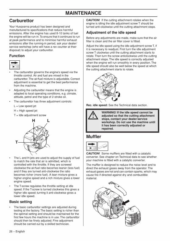
• The carburettor has three adjustment controls:
L = Low speed jet
H = High speed jet
T = Idle adjustment screw
• The L and H-jets are used to adjust the supply of fuel to match the rate that air is admitted, which is controlled with the throttle. If they are screwed clockwise the air/fuel ratio becomes leaner (less fuel) and if they are turned anti-clockwise the ratio becomes richer (more fuel). A lean mixture gives a higher engine speed and a rich mixture gives a lower engine speed.
• The T-screw regulates the throttle setting at idle speed. If the T-screw is turned clockwise this gives a higher idle speed; turning it anti-clockwise gives a lower idle speed.
Basic setting• The basic carburettor settings are adjusted during
testing at the factory. The basic setting is richer than the optimal setting and should be maintained for the first few hours the machine is in use. The carburettor should then be finely adjusted. Fine adjustment should be carried out by a skilled technician.
CAUTION! If the cutting attachment rotates when the engine is idling the idle adjustment screw T should be turned anti-clockwise until the cutting attachment stops.
Adjustment of the idle speedBefore any adjustments are made, make sure that the air filter is clean and the air filter cover is fitted.
Adjust the idle speed using the idle adjustment screw T, if it is necessary to readjust. First turn the idle adjustment screw T clockwise until the cutting attachment starts to rotate. Then turn the screw anticlockwise until the cutting attachment stops. The idle speed is correctly adjusted when the engine will run smoothly in every position. The idle speed should also be well below the speed at which the cutting attachment starts to rotate.
Rec. idle speed: See the Technical data section.
Muffler
CAUTION! Some mufflers are fitted with a catalytic converter. See chapter on Technical data to see whether your machine is fitted with a catalytic converter.
The muffler is designed to reduce the noise level and to direct the exhaust gases away from the operator. The exhaust gases are hot and can contain sparks, which may cause fire if directed against dry and combustible material.
T
H L!
WARNING! If the idle speed cannot be adjusted so that the cutting attachment stops, contact your dealer/service workshop. Do not use the machine until it has been correctly adjusted or repaired.
MAINTENANCE
Some mufflers are equipped with a special spark arrestor mesh. If your machine has this type of muffler, you should clean the mesh at least once a week. This is best done with a wire brush.On mufflers without a catalytic converter the mesh should be cleaned weekly, or replaced if necessary. On mufflers fitted with a catalytic converter the mesh should be checked, and if necessary cleaned, monthly. If the mesh is damaged it should be replaced.
If the mesh is frequently blocked, this can be a sign that the performance of the catalytic converter is impaired. Contact your dealer to inspect the muffler. A blocked mesh will cause the machine to overheat and result in damage to the cylinder and piston. See also instructions under the heading Maintenance.
CAUTION! Never use a machine with a defective muffler.
Cooling system
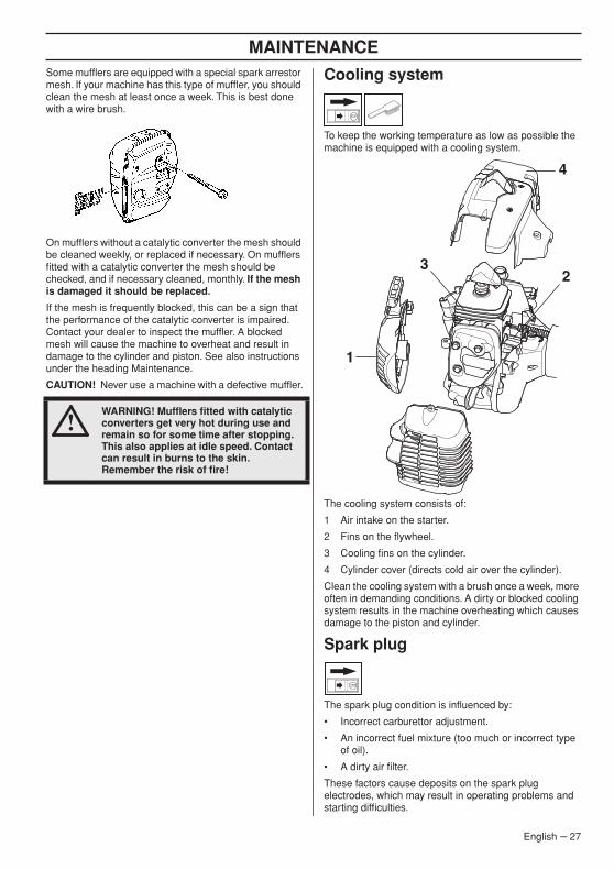
To keep the working temperature as low as possible the machine is equipped with a cooling system.
The cooling system consists of:
1 Air intake on the starter.
2 Fins on the flywheel.
3 Cooling fins on the cylinder.
4 Cylinder cover (directs cold air over the cylinder).
Clean the cooling system with a brush once a week, more often in demanding conditions. A dirty or blocked cooling system results in the machine overheating which causes damage to the piston and cylinder.
Spark plug
The spark plug condition is influenced by:
• Incorrect carburettor adjustment.
• An incorrect fuel mixture (too much or incorrect type of oil).
• A dirty air filter.
These factors cause deposits on the spark plug electrodes, which may result in operating problems and starting difficulties.
!WARNING! Mufflers fitted with catalytic converters get very hot during use and remain so for some time after stopping. This also applies at idle speed. Contact can result in burns to the skin. Remember the risk of fire!
1
23
4
English – 27

MAINTENANCE
If the machine is low on power, difficult to start or runs poorly at idle speed: always check the spark plug first before taking any further action. If the spark plug is dirty, clean it and check that the electrode gap is 0,5 mm. The spark plug should be replaced after about a month in operation or earlier if necessary.CAUTION! Always use the recommended spark plug type! Use of the wrong spark plug can damage the piston/cylinder. Check that the spark plug is fitted with a suppressor.
Air filter
The air filter must be regularly cleaned to remove dust and dirt in order to avoid:
• Carburettor malfunctions
• Starting problems
• Loss of engine power
• Unnecessary wear to engine parts.
• Excessive fuel consumption.
Clean the filter every 25 hours, or more regularly if conditions are exceptionally dusty.
Cleaning the air filterRemove the air filter cover and take out the filter. Blow clean with compressed air.
Gear
IMPORTANT!
All service on the saw head must be carried out by an authorized Husqvarna dealer. Always use Husqvarna's original grease to prevent damage to the gear in the saw head.
Use grease with part number: 579 06 49-01
28 – English

MAINTENANCE
Maintenance scheduleThe following is a list of the maintenance that must be performed on the machine. Most of the items are described in the Maintenance section. The user must only carry out the maintenance and service work described in this Operator’s Manual. More extensive work must be carried out by an authorized service workshop.
Maintenance Daily maintenance
Weekly maintenance
Monthly maintenance
Clean the outside of the machine. X
Make sure the throttle trigger lock and the throttle function correctly from a safety point of view.
X
Check that the stop switch works correctly. X
Check that the cutting attachment does not rotate at idle. X
Clean the air filter. Replace if necessary. X
Check that nuts and screws are tight. X
Check that there are no fuel leaks from the engine, tank or fuel lines.
X
Clean the area under the protective cover. X
Check the saw chain with regard to visible cracks in the rivets and links, whether the saw chain is stiff or whether the rivets and links are abnormally worn.
X
Check the starter and starter cord. X
Check that the vibration damping elements are not damaged. X
Clean the outside of the spark plug. Remove it and check the electrode gap. Adjust the gap to 0.5 mm or replace the spark plug. Check that the spark plug is fitted with a suppressor.
X
Clean the machine’s cooling system. X
Clean or replace the spark arrestor mesh on the muffler (only applies to mufflers without a catalytic converter).
X
Clean the outside of the carburettor and the space around it. X
File off any burrs from the edges of the bar. X
Clean the fuel tank. X
Check the fuel filter from contamination and the fuel hose from cracks or other defects. Replace if necessary.
X
Check all cables and connections. X
Check the clutch, clutch springs and the clutch drum for wear. Replace if necessary by an autorized service workshop.
X
Replace the spark plug. Check that the spark plug is fitted with a suppressor.
X
Check and clean the spark arrestor mesh on the muffler (only applies to mufflers fitted with a catalytic converter).
X
English – 29
TECHNICAL DATA
Technical data
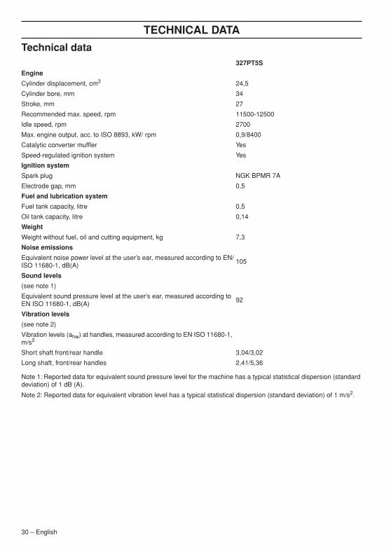
Note 1: Reported data for equivalent sound pressure level for the machine has a typical statistical dispersion (standard deviation) of 1 dB (A).
Note 2: Reported data for equivalent vibration level has a typical statistical dispersion (standard deviation) of 1 m/s2.
327PT5S
Engine
Cylinder displacement, cm3 24,5
Cylinder bore, mm 34
Stroke, mm 27
Recommended max. speed, rpm 11500-12500
Idle speed, rpm 2700
Max. engine output, acc. to ISO 8893, kW/ rpm 0,9/8400
Catalytic converter muffler Yes
Speed-regulated ignition system Yes
Ignition system
Spark plug NGK BPMR 7A
Electrode gap, mm 0,5
Fuel and lubrication system
Fuel tank capacity, litre 0,5
Oil tank capacity, litre 0,14
Weight
Weight without fuel, oil and cutting equipment, kg 7,3
Noise emissions
Equivalent noise power level at the user’s ear, measured according to EN/ISO 11680-1, dB(A)
105
Sound levels
(see note 1)
Equivalent sound pressure level at the user’s ear, measured according to EN ISO 11680-1, dB(A)
92
Vibration levels
(see note 2)
Vibration levels (ahw) at handles, measured according to EN ISO 11680-1, m/s2
Short shaft front/rear handle 3,04/3,02
Long shaft, front/rear handles 2,41/5,36
30 – English

TECHNICAL DATA
Guide bar and chain combinationsEC-declaration of conformity (Applies to Europe only)Husqvarna AB, SE-561 82 Huskvarna, Sweden, tel +46-36-146500, declares under sole responsibility that the pruning saws Husqvarna 327PT5S dating from 2011 serial numbers and onwards (the year is clearly stated on the rating plate, followed by the serial number), comply with the requirements of the COUNCIL’S DIRECTIVE:
- of May 17, 2006 "relating to machinery" 2006/42/EC
- of December 15, 2004 ”relating to electromagnetic compatibility” 2004/108/EC.
The following standards have been applied: EN ISO 12100-2:2003, CISPR 12:2005, EN ISO 11680-1:2008
SMP Svensk Maskinprovning AB, Fyrisborgsgatan 3, SE-754 50 Uppsala, Sweden, has performed voluntary type examination on behalf of Husqvarna AB. The certificates are numbered:
0404/11/2312
Huskvarna 30 June 2011.
Bengt Frögelius, Development manager (Authorized representative for Husqvarna AB and responsible for technical documentation.)
The following combinations are CE approved.
Guide bar Saw chain
Length, inch Pitch, inch Max. no of teeth on tip sprocket
10 1/4 - Husqvarna H00
12 1/4 - Husqvarna H00
D2
L
_D
PITCH =
English – 31


Original instructions
´®z+UI,¶6B¨´®z+UI,¶6B¨2012-11-30
1153411-26