operadic analysis of distributed systems - mit...
TRANSCRIPT

NASA/CR–2015–xxxxxx
Operadic Analysis of DistributedSystems
Kevin Schweiker, Srivatsan VaradarajanHoneywell Aerospace Advanced TechnologyPlatforms SystemsGolden Valley, MN 55422, USA
David Spivak, Patrick Schultz, Ryan Wisnesky, Marco PerezMassachusetts Institute of TechnologyDepartment of MathematicsCambridge, MA 02139, USA
September 2015
NASA STI Program . . . in Profile
Since its founding, NASA has been dedicatedto the advancement of aeronautics and spacescience. The NASA scientific and technicalinformation (STI) program plays a key partin helping NASA maintain this importantrole.
The NASA STI Program operates under theauspices of the Agency Chief InformationOfficer. It collects, organizes, provides forarchiving, and disseminates NASA’s STI.The NASA STI Program provides access tothe NASA Aeronautics and Space Databaseand its public interface, the NASA TechnicalReport Server, thus providing one of thelargest collection of aeronautical and spacescience STI in the world. Results arepublished in both non-NASA channels andby NASA in the NASA STI Report Series,which includes the following report types:
• TECHNICAL PUBLICATION. Reports ofcompleted research or a major significantphase of research that present the resultsof NASA programs and include extensivedata or theoretical analysis. Includescompilations of significant scientific andtechnical data and information deemed tobe of continuing reference value. NASAcounterpart of peer-reviewed formalprofessional papers, but having lessstringent limitations on manuscript lengthand extent of graphic presentations.
• TECHNICAL MEMORANDUM.Scientific and technical findings that arepreliminary or of specialized interest, e.g.,quick release reports, working papers, andbibliographies that contain minimalannotation. Does not contain extensiveanalysis.
• CONTRACTOR REPORT. Scientific andtechnical findings by NASA-sponsoredcontractors and grantees.
• CONFERENCE PUBLICATION.Collected papers from scientific andtechnical conferences, symposia, seminars,or other meetings sponsored orco-sponsored by NASA.
• SPECIAL PUBLICATION. Scientific,technical, or historical information fromNASA programs, projects, and missions,often concerned with subjects havingsubstantial public interest.
• TECHNICAL TRANSLATION. English-language translations of foreign scientificand technical material pertinent toNASA’s mission.
Specialized services also include creatingcustom thesauri, building customizeddatabases, and organizing and publishingresearch results.
For more information about the NASA STIProgram, see the following:
• Access the NASA STI program home pageat http://www.sti.nasa.gov
• E-mail your question via the Internet [email protected]
• Fax your question to the NASA STI HelpDesk at 443-757-5803
• Phone the NASA STI Help Desk at443-757-5802
• Write to:NASA STI Help DeskNASA Center for AeroSpace Information7115 Standard DriveHanover, MD 21076–1320

NASA/CR–2015–xxxxxx
Operadic Analysis of DistributedSystems
Kevin Schweiker, Srivatsan VaradarajanHoneywell Aerospace Advanced TechnologyPlatforms SystemsGolden Valley, MN 55422, USA
David Spivak, Patrick Schultz, Ryan Wisnesky, Marco PerezMassachusetts Institute of TechnologyDepartment of MathematicsCambridge, MA 02139, USA
National Aeronautics andSpace Administration
Langley Research CenterHampton, Virginia 23681-2199
September 2015
The use of trademarks or names of manufacturers in this report is for accurate reporting and does notconstitute an offical endorsement, either expressed or implied, of such products or manufacturers by theNational Aeronautics and Space Administration.
Available from:NASA Center for AeroSpace Information
7115 Standard DriveHanover, MD 21076-1320
443-757-5802

Abstract
Establishing an assurance claim for a distributed safety critical system has proven extremely diffi-cult. Developing and documenting the evidence needed to support a claim requires diverse modelsand abstractions of system properties to capture behaviors, understand error propagation, and eval-uate the interactions with other systems and humans. The ability to scale and merge these diversemodels and abstractions within a sound mathematical framework is the subject of this technicalreport. Category theory is one promising approach for this mathematical framework. A highercategory theory known as operad theory is described and used to evaluate the effects of disrup-tions and failures of NextGen communication channels on the safe separation of aircraft within theNational Airspace (NAS).
1

Contents
1 Introduction 31.1 Scope . . . . . . . . . . . . . . . . . . . . . . . . . . . . . . . . . . . . . . . . . . . . 31.2 Motivation . . . . . . . . . . . . . . . . . . . . . . . . . . . . . . . . . . . . . . . . . 31.3 Category Theory is a Natural Fit . . . . . . . . . . . . . . . . . . . . . . . . . . . . . 4
2 Problem Description 62.1 National Airspace System Circa 2015 . . . . . . . . . . . . . . . . . . . . . . . . . . . 7
2.1.1 Weather Conditions and Flight Rules . . . . . . . . . . . . . . . . . . . . . . 72.1.2 Airspace Classifications . . . . . . . . . . . . . . . . . . . . . . . . . . . . . . 82.1.3 Air Traffic Control in the United States . . . . . . . . . . . . . . . . . . . . . 102.1.4 Situational Awareness for Air Traffic Control . . . . . . . . . . . . . . . . . . 112.1.5 Safe Separation . . . . . . . . . . . . . . . . . . . . . . . . . . . . . . . . . . . 12
2.2 National Air Space - NextGen . . . . . . . . . . . . . . . . . . . . . . . . . . . . . . . 132.2.1 NextGen Programs . . . . . . . . . . . . . . . . . . . . . . . . . . . . . . . . . 132.2.2 NextGen Technologies . . . . . . . . . . . . . . . . . . . . . . . . . . . . . . . 14
2.3 Challenges . . . . . . . . . . . . . . . . . . . . . . . . . . . . . . . . . . . . . . . . . . 16
3 Category Theory 183.1 History . . . . . . . . . . . . . . . . . . . . . . . . . . . . . . . . . . . . . . . . . . . 18
3.1.1 Topology and Algebra . . . . . . . . . . . . . . . . . . . . . . . . . . . . . . . 183.1.2 Applications outside of math . . . . . . . . . . . . . . . . . . . . . . . . . . . 18
3.2 Operads . . . . . . . . . . . . . . . . . . . . . . . . . . . . . . . . . . . . . . . . . . . 193.2.1 First example of operad and algebra . . . . . . . . . . . . . . . . . . . . . . . 203.2.2 Variety of operads and algebras . . . . . . . . . . . . . . . . . . . . . . . . . . 21
4 Category Theory and the National Airspace 234.1 Operads for wiring diagrams of dynamical systems . . . . . . . . . . . . . . . . . . . 23
4.1.1 The operad W of wiring diagrams . . . . . . . . . . . . . . . . . . . . . . . . 234.1.2 The algebra D : W → Set of dynamic systems . . . . . . . . . . . . . . . . . . 25
4.2 Diagrams and Description . . . . . . . . . . . . . . . . . . . . . . . . . . . . . . . . . 264.3 Analysis Possibilities . . . . . . . . . . . . . . . . . . . . . . . . . . . . . . . . . . . . 32
5 Final Remarks 355.1 Conclusions . . . . . . . . . . . . . . . . . . . . . . . . . . . . . . . . . . . . . . . . . 355.2 Future Work . . . . . . . . . . . . . . . . . . . . . . . . . . . . . . . . . . . . . . . . 35
6 SOW Checklist 37
A Acronyms 41

List of Figures
1 Transition of current NAS to NextGen with Internet Protocol (IP) Technologies . . . 62 Controlled Air Space within the NAS . . . . . . . . . . . . . . . . . . . . . . . . . . . 83 Hierarchical Control of the NAS . . . . . . . . . . . . . . . . . . . . . . . . . . . . . . 104 Fatalities during the Jet Age (courtesy of Boeing)[1] . . . . . . . . . . . . . . . . . . 115 NextGen Communications used to aid Aircraft Separation . . . . . . . . . . . . . . . . 156 Typical Control Theory Diagram . . . . . . . . . . . . . . . . . . . . . . . . . . . . . 267 (a)Top: Wiring Diagram of the Logical NAS, (b)Bottom:Wiring Digram of the Phys-
ical NAS . . . . . . . . . . . . . . . . . . . . . . . . . . . . . . . . . . . . . . . . . . . 29
2

1 Introduction
The documented work was performed under NASA Task Order NNL14AA05C, Category-TheoreticApproaches for the Analysis of Distributed Systems.
1.1 Scope
National Aeronautics and Space Administration (NASA)’s Aviation Safety Program’s System-wideSafety and Assurance Technologies (SSAT) project seeks to identify risks and provide knowledgerequired to safely manage increasing complexity in the design and operation of vehicles and theair transportation systems, including advanced approaches to enable improved and cost-effectiveverification and validation of flight-critical systems. SSAT is focused on methods to assess andensure system-wide safety of complex aviation systems.
This effort supports SSAT by conducting research directed at improving the safety of currentand future aircraft operating in the National Airspace System. UnderSSAT there is a technicalchallenge that targets the Assurance of Flight Critical Systems (AFCS) a technical challenge thataddresses, among other things, the sound assurance of safety-critical distributed systems propertiesand the complex interactions between systems and subsystems. In particular, this effort is beingconducted in response to NASA Research Opportunities in Aeronautics (ROA) 2013 SSAT SubtopicNumber AFCS 1.5: Distributed Systems: Distributed Airspace Systems.
1.2 Motivation
Public benefits derived from continued growth in the transport of passengers and cargo are depen-dent on the improvement of the intrinsic safety attributes of current and future air vehicles thatwill operate in the Next Generation Air Transport System (NextGen). A central goal of NextGen is toimprove the efficiency and capacity of National Airspace (NAS) and more specifically our nation’sairports through the strategic use of existing and emerging technologies. Automation will play avital role in the realization of this goal through a broad range of applications such as automat-ing low-level background activities to free human operators to focus on higher-complexity tasks,providing automated advisories to a human operator to support decision-making, or completelyreplacing some instances of human decision-making.
In addition to automation, NextGen will require coordination and cooperation between unprece-dented numbers of disparate system elements using a wide range of communication protocols.System functions that historically have been provided locally using dedicated resources may be dis-tributed among a network of ground, airborne and space-based resources. The introduction of anautomated system that functions on a decentralized rather than localized networks will present sig-nificant challenges to NextGen safety initiatives. Further research is needed to develop capabilitiesto analyze and assess flight safety of NextGen capabilities from a distributed systems perspective.
Our approach in this project is to use category theoretic structure of operads as a basis foranalysis of distributed systems at the NAS level. Operads provide a concise and transparent methodto develop consensus among stakeholders. Operads also allow for the “chunking” of the problemspace along different view modalities, such as logical and physical. Operads, when constructedproperly, allow for the generation of a hierarchical algebra, which allows the analysis to exploredifferent levels of abstraction with the guarantee that lower level system views correctly composeinto the higher-level views.
3

1.3 Category Theory is a Natural Fit
Formal Methods (FMs) are mathematical techniques for the specification, development and veri-fication of cyberphysical systems. The use of FMs arose in computer science to develop reliableand robust designs. Today, techniques in FMs borrow heavily from theoretical computer sciencefundamentals including: type systems, formal languages, semantics, and algebraic data types. Thevalue of FMs is that they provide rigorous methods to examine the entire state space of a digitalcyberphysical design and establish a specific system characteristic is true for all possible inputs.
FMs have found wide spread use in the analysis of airspace problems. National Aeronauticsand Space Administration (NASA)’s Langley Formal Methods program Airborne Coordinated Con-flict Resolution and Detection (ACCORD), developed a framework for the formal specification andverification of state-based conflict detection and resolution algorithms[2]. ACCORD provides: a3-D conflict detection algorithm, that is proven to be complete and correct; a 3-D conflict reso-lution algorithm; a loss of separation recovery algorithm that is proven correct; a 3-D preventionbands algorithm that computes all the critical vectors. The formal specification as and proofs forthe ACCORD framework are publicly available on the NASA’s Prototype Verification System (PVS)Library [3].
FMs are still unfortunately used sparingly by systems engineering professionals. This limitationis due to the complexity of real systems and the step learning curve on most FMs tools. Twogeneral approaches have guided the use of FMs over the years: first, apply FMs to requirements andsimplified designs; and, second, apply FMs to only the most critical components.
Formal modeling is typically—but not exclusively—used to reason about system’s intrinsic be-havior. Formal modeling helps to document and reason about non-functional properties. Numerousarchitectural FM languages, including AADL[4], EAST-ADL [5], and SYSML [6] have emerged inthe past decade with renewed interest in Model Based Systems Engineering (MBSE)[7]. Analysistools support the models developed using architectural modeling notations. While mathematicallogic is a unifying aspect of FMs, there is no single best “formal method”. Some analysis are bestperformed using a model checker such as: Symbolic Analysis Laboratory (SAL) [8], UPPAAL [9],KIND [10], and Probabilistic Model Checker (PRISM) [11]. While other types analysis are bettersuited to a theorem prover or proof assistant, such as: PVS [12], Coq [13], A Computational Logicfor Applicative Common Lisp (ACL2) [14], or Isabelle [15].
While introducing formal modeling methodology into a distributed system development effortcan improve the documentation and quality of the system, it comes at a high cost. In particular,it means there are multiple separate model artifacts that needs be maintained and kept consistentat different levels of system decomposition e.g. at System of Systems (SoS) level, at each Systemlevel and at multiple Components level within each System. Ensuring their consistency is ad-hoc, as each language has its own syntax and semantics with no connections between them andno appropriate mathematical rigor underpinning such translation and composition of systems. Atbest, the additional effort required to keep the models consistent outweighs the benefits of increasedassurance. At worst, it provides a false sense of assurance, where the implementation does notsatisfy properties specified in architectural formal models.
The central thesis of our project is that Category Theory (CT) is a natural framework for suchFMs modeling and analysis tools whereby the composition of each of the modular systems or theoverall system-of-systems are then characterized with and regulated by underlying mathematicalrigor. CT also fits readily with other mathematical analysis techniques: dynamical systems, al-gebraic datatypes, logic, etc. The method from category theory that we are using in this reportrelates to operads [16] where an operad consists of a few interlocking mathematical components:objects (interfaces, building blocks, etc), morphisms (arrangements, building instructions, etc) and
4

compositional formula (nesting, instruction trees, etc).CT then provides the basis for analyzing safety properties of systems and SoS by providing an
algebra for compositional operations like nesting, zooming, chunking, panning etc. As will be shownin this work, by restricting system specification to few basic rules and constraints, the larger systemand SoS properties than can be easily managed and controlled. Further, CT overcomes one of thefundamental limitation in the applicability of FM to design and verification of large and complexsystems and SoS (in general systems engineering), namely the steep learning curve for organizationsto imbibe formalism and mathematical rigor to safety assessment processes that especially spanmultiple organizations involved in the process. Once the CT specification is complete, the math“gets out of your way”: the safety assessment processes and associated personnel can proceedoblivious to the the underling CT specification guiding the process that keeps the system safety incheck.
5

2 Problem Description
National authorities, such as the Federal Aviation Administration (FAA), have developed verti-cal, lateral, longitudinal separation standards to support safe navigation of aircraft in controlledairspace. These standards are designed to minimize ground and airborne hazards while limiting ex-posure to wake vortex turbulence. For the United States, these separation criteria are documentedin the FAA administrative order JO 7100.65U, Air Traffic Control [17].
The next generation of air traffic management systems (NextGen) will involve significant changesfrom the way Air Traffic Control (ATC) is done today. Reliance on software is increasing and allowinggreater system complexity. Humans are assuming supervisory roles over automation, requiring morecognitively complex human decision-making. Control is shifting from the ground to the aircraftand to shared responsibilities. In addition, coupling and interconnection between land, airborne,and space systems introduces more potential for accidents stemming from unsafe and unintendedcomponent interactions.
Figure 1: Transition of current NAS to NextGen with IP Technologies
(a) Current NAS
(b) NextGen NAS
NextGen is a modernization effort of NAS by FAA to transform the nation’s ground-based ATC
6

system into a more precise satellite based system and other advanced digital technologies. Thiseffort will involve multi-year incremental transition with introduction of new technologies andthe leveraging of existing technologies, which will impact every aspect of NAS including a seamlessintegration to a modern IP based communication network. Please see figure 1, provided by courtesyof [18], for an illustration of different parts of the NAS, the information flow between them thatimproves situational awareness of pilots and ground controllers and their transition to the nextgeneration IP network.
We provide some high level description of the digital technologies, different entities and assets inthe system (including humans and organizations) involved the current NAS and the future NextGen
initiatives already underway in sections 2.1 and 2.2 and subsequently describe some challenges tomodeling those systems in section 2.3.
2.1 National Airspace System Circa 2015
The National Airspace (NAS), prior to the widespread adoption of Next Generation Air TransportSystem (NextGen) technologies, is a complex System of Systems (SoS), comprised of many distributedsystems, people, and Air Traffic Control (ATC) procedures. Even though the NAS is a distributedSoS, the control of individual airplanes remains remarkably centralized. This section provides abrief overview of the ATC system used by the Federal Aviation Administration (FAA) to managethe nation’s airspace.
The FAA was established in by the Federal Aviation Act of 1958 and was made responsible forthe control and use of navigable airspace within the United States. The FAA then created andevolved the NAS over the years with the primary purpose of protecting protect people and propertyon the ground, while maintaining a safe and efficient airspace environment for civil, commercial,and military aviation. The NAS is comprised of a network of navigation facilities, ATC facilities,airports, technology, and policy, rules, and regulations that define the system.
2.1.1 Weather Conditions and Flight Rules
Efficient operation of the NAS helps drive the economy of the United States. In 2012, civil aviationalone accounted for 5.4% of the Gross Domestic Product (GDP) and supported nearly 12 millionjobs [19] . Weather significantly impacts the operation of the NAS. For example, weather conditionsdetermine the flight rules under which airplanes can operate and can also affect safe separation,the physical distance required between airplanes. Safe separation of airplanes is a key parameterto ensure the overall safe operation of the NAS. The required separation may vary depending onairplanes’ type, weather, and flight rules. Safe separation requirements usually increase duringpoor weather conditions, as it is more difficult for a pilot to maintain local situational awareness.Increased safe separation during the terminal phase of flight can reduce airport capacity, as lessairplanes can use an airport during a given time interval. Conversely, reduced safe separation duringthe terminal phase can increase airport capacity, as more airplanes can use an airport during a giventime interval. This increase in capacity may be limited by local noise restrictions.
Civil airplanes operate under two distinct categories of operational flight rules: Visual FlightRules (VFR) and Instrument Flight Rules (IFR). These flight rules are linked to the two categoriesof weather conditions: Visual Meteorological Conditions (VMC) and Instrument MeteorologicalConditions (IMC). VMC exist during generally fair to good weather, and IMC exist during times ofrain, low clouds, or reduced visibility. IMC generally exist whenever visibility falls below 3 StatuteMiles (SM) or the ceiling drops below 1,000 feet above ground level (AGL). The ceiling is thedistance from the ground to the bottom of a cloud layer that covers more than 50% of the sky.
7

Figure 2: Controlled Air Space within the NAS
During VMC, airplanes may operate under VFR, and the pilot is primarily responsible for seeingother airplanes and maintaining safe separation. Airplanes operating under VFR typically navigateby orientation to geographic and other visual references. This is the mode of operation preferredby many general aviation airplanes.
During IMC, airplanes must operate under IFR. If an airplane or pilot is not rated for IFR thenthey can not fly during IMC. IFR airplanes fly assigned routes and altitudes, and use a combinationof radio Navigational Aids (NAVAIDS) and vectors from ATC to navigate. A key feature of the NAS isthat ATC exercises positive control (i.e., separation of all air traffic within designated airspace) overall airplanes in controlled airspace. Simply put, the primary products of ATC are safe separationservices. Airplanes may elect to operate IFR in VMC. The majority of commercial air traffic(including all air carrier traffic), regardless of weather, operate under IFR as required by FederalAviation Regulations. ATC has the discretion to allow IFR airplanes to maintain visual separation.This is typically only done during good weather in an attempt to increase airport capacity.
2.1.2 Airspace Classifications
The FAA has designated six classes of airspace within the NAS, in accordance with International CivilAviation Organization (ICAO) airspace classifications. Figure 2 and Table 1 identifies both airspaceclassifications and terminology. Airspace is broadly classified as either controlled or uncontrolled.Airspace designated as Class A, B, C, D, or E is controlled airspace. Class F airspace is notused in the United States. Class G airspace is uncontrolled airspace. Controlled airspace meansthat IFR services are available to airplanes that elect to file IFR flight plans; it does not meanthat all flights within the airspace are controlled by ATC. IFR services include ground-to-air radiocommunications, navigation aids, and air traffic (i.e., separation) services. Airplanes can operateunder IFR in uncontrolled airspace; however, the airplanes cannot file an IFR flight plan and IFR
services are not necessarily available. Controlled airspace is intended to ensure separation of IFR
traffic from other airplanes, both IFR and VFR.
The airspace classifications discussed in this section are designed primarily to manage VFR
traffic in controlled airspace. The controlled airspace classifications do not affect IFR operations,as IFR traffic is cleared through controlled airspace automatically by ATC. VFR airplanes mayoperate in Class E controlled airspace without control by ATC, so long as weather conditionspermit visual separation of airplanes (during IMC, VFR traffic is prohibited and thereby ensuresseparation between VFRand IFR traffic). Also, air traffic service is provided to VFR airplanes inClass E airspace only when ATC workload permits. VFR airplanes operating in class B, C, and Dairspace must be in contact with ATC; this gives ATC the authority to manage VFR airplanes inthe proximity of busy airports. Essentially, the controlled airspace system protects IFR airplanesfrom VFR airplanes during IMCand in close proximity to busy airports. Note that the boundaries ofairspace class areas do not necessarily correlate with the boundaries and sectors of ATC facilities.
8

Table 1: NAS Air Space Class Description [20]
NAS
ClassDescription
A Generally, that airspace from 18,000 feet Mean Sea Level (MSL) up to and including60,000 MSL, including the airspace overlying the waters within 12 Nautical Miles (NM) ofthe coast of the 48 contiguous States and Alaska. Unless otherwise authorized, all personsmust operate their airplanes under IFR.
B Generally, that airspace from the surface to 10,000 feet MSL surrounding the nation’s bus-iest airports in terms of airport operations or passenger enplanements. The configurationof each Class B airspace area is individually tailored and consists of a surface area and twoor more layers, and is designed to contain all published instrument procedures. An ATC
clearance is required for all airplanes to operate in the area, and all airplanes that are socleared receive separation services within the airspace. The cloud clearance requirementfor VFR operations is “clear of clouds.”
C Generally, that airspace from the surface to 4,000 feet above the airport elevation (chartedin MSL) surrounding those airports that have an operational control tower, are serviced bya radar approach control, and that have a certain number of IFR operations or passengerenplanements. Although the configuration of each Class C area is individually tailored,the airspace usually consists of a surface area with a 5 NM radius, an outer circle witha 10 NM radius that extends from no lower than 1,200 feet up to 4,000 feet above theairport elevation. Each person must establish two-way radio communications with theATC facility providing air traffic services prior to entering the airspace and thereaftermaintain those communications while within the airspace
D Generally, that airspace from the surface to 2,500 feet above theairport elevation (chartedinMSL) surrounding those airports that have an operational control tower.The configura-tion of each Class D airspace area is individually tailored and when instrument proceduresare published, the airspace will normallybe designed to contain the procedures. Arrivalextensions for instrument approach procedures maybe Class D or Class E airspace. Un-less otherwiseauthorized, each person must establish two-way radio communications withthe ATC facility providing air traffic services prior to enteringthe airspace and thereaftermaintain those communications while in the airspace. No separation services are providedto VFR airplanes.
E Generally, if the airspace is not Class A, Class B, Class C, or Class D, and it is controlledairspace, it is Class E airspace. The types of Class E airspace areas are defined in greaterdetail in [20]
F Not Applicable within United States
G Uncontrolled airspace. All airspace that has not been designated as Class A, Class B,Class C, Class D, or Class E airspace.
9

Figure 3: Hierarchical Control of the NAS
2.1.3 Air Traffic Control in the United States
The NAS is a hierarchically organized and controlled SoS. Currently, the NAS is divided into 21zones, known as Air Traffic Control System Command Center (ATCSCC), which oversees all airtraffic control within its zone. Each ATCSCC is sub-divided into sectors that include open air-space and regions around airports. For each ATCSCC there is one corresponding Air Route TrafficControl Center (ARTCC) that manages traffic within all sectors of its center except for TerminalRadar Approach Control (TRACON) airspace and local-airport airspace. Within about 50 NM ofmajor airports the TRACON that manages air traffic within its domain, coordinating the departingand arriving air traffic within its space. There is a Air Traffic Control Tower (ATCT) located ateach airport that has regularly scheduled flights, as well as at some other airports. The ATCT
coordinates ground traffic at its airport and air traffic within 5 NM. This hierarchical system isillustrated in Figure 3.
A flight between two airports, in the controlled portions of the NAS, involve seven separateaspects of flight including: preflight, takeoff, departure, en route, decent, approach, and landing.During each of these phases the airplanes is controlled by one of the three NAS control elementsand is handed off from controller to controller as the flight progresses.
The ATCT is responsible for the airplanes during preflight, including coordination of push-backfrom the gate, to authorization to taxi, to assignment of runways; to take-off where the pilotpowers up the airplanes and accelerates the runway; to departure, where the plane lifts off theground and begins to climb to a cruising altitude. At this point the ATCT hands off control of theairplanes to the responsible TRACON.
TRACON is responsible for managing the remainder of the departure phase while the airplaneis within its space. As the airplane is about the transition the TRACON boundary it is handed offto an ARTCC controller. Depending on the length of flight multiple ARTCCs may be involved inmanaging the airplane during the en route phase of flight.
As the airplane approaches its destination airport the process in reverse. The ARTCC willtransition control for management to the responsible TRACON that will sequence and space arriving
10

Figure 4: Fatalities during the Jet Age (courtesy of Boeing)[1]
airplane during the decent and approach phases to line up the airplane with a designated runwaythat will maximize efficiency while mitigating noise concerns of the surrounding community. Oncethe airplane is within 5 NM of the destination airport the local ATCT ( if there is one) will managethe final approach and landing, including the management of taxiways and gate approach.
2.1.4 Situational Awareness for Air Traffic Control
The tools for aiding the various layers of air traffic control in the United States has remainedvirtually unchanged since the 1960s. For the ATCT, the main Situational Awareness (SA) aids areeyes, binoculars, cameras, ground detecting radars, and radio communications with pilots of theairplanes and land line communications with TRACON and the ARTCC.
At the TRACON level the controller’s SA is aided by Primary Search Radar (PSR)s and SecondarySearch Radar (SSR)s, radio contact with pilots and land lines to nearby ATCTs and ARTCCs. Com-puters aid with sequencing and safe separation estimates. Each PSR generates non-cooperativerange and angle estimates of the air traffic within the range of the radar. SSRs are used in a cooper-ative manor to obtain information from each airplanes equipped with an operational transponder.Depending on the transponder type, the interrogated transponder will respond to a request fromthe SSR with information such as the airplane’s identification and altitude.
The NAS is an incredibly safe SoS. Its remarkable safety record has evolved through the use oftime-tested technologies on the ground and in the airplane, along with policies and procedures thatcan be modified when safety issues are detected. In a statistical study published by Boeing Com-mercial Airplanes [1] fatalities due to airplane crashes has reduced nearly two orders of magnitudesince the advent of the NAS.
This reduction in mortality is due improvements in the design and production of airplanes andavionics, enhanced pilot and controller training, and the evolution of ATC policies and procedureswhen safety issues are detected within the NAS. This evolutionary feature of the NAS has resultedin this SoS being nearly as safe as practically and economically possible.
11

The versatility of the positive control exercised by ATC in the NAS was demonstrated on Septem-ber 11, 2001. Once the unprecedented order was given to close the NAS controllers immediatelyhalted all take-offs nationwide then proceeded to guide 4,500 planes carrying 350,000 passengers inNAS to safe landings. Nearly 75 percent of these planes were on the ground within an hour. Duringthe first quarter of an hour ATC rerouted planes at a rate of one per second. Within 21
2 hours ofthe orders being issued, ATC cleared the NAS without any loss of safe separation.[21].
2.1.5 Safe Separation
National authorities specify vertical and horizontal separation standards to facilitate the safe navi-gation of airplanes in their sovereign controlled airspace([?]). Observance of these standards ensuressafe separation from the ground, from other airplanes, and from protected airspace. Loss of Sepa-ration safety hazard between airborne aircraft then occurs whenever specified separation minima incontrolled airspace are breached. Separation standards may sometimes serve to reduce exposure toWake Vortex Turbulence although there are many occurrences of significant wake vortex encounterat separations much greater than prevailing minimum separation.
Separation standards in the United States are based on the provisions of ICAO Doc 4444 [22].The techniques and procedures to achieve and used to achieve separation are the primary serviceprovided by ATC. Separation occurs along the 3 physical axes referred to as: vertical, longitudinal,and lateral.
Vertical separation is achieved by requiring airplanes to use a prescribed altimeter pressuresetting within designated airspace, and to operate at different levels expressed in terms of altitudeor flight level. Flight Level (FL) are described by a number, which is based on the local barometricaltitude in feet, divided by 100. Therefore, an apparent altitude of 29,000 feet is referred to asFL290. The ICAO species a minimum vertical separation for IFR flight as 1000 ft below FL290 and2000 ft above FL290. To make the airspace more efficient and allow for additional air routes, theUnited States, Canada and Mexico adapted Reduced Vertical Separation Minima (RVSM) in 2005between FL 290 and FL 410. For qualified airplanes, this reduces the vertical separation above FL290 to 1,000 ft. At FL 410 and above, 4,000 ft intervals are required to separate same-directionairplanes and only odd FLs are assigned, depending on the direction of flight. Permissible altitudesare dependent upon compass direction.
• Heading 000 to 179o: Between FL290 and FL410 odd thousands (FL 290, 310, 330, etc.)Between FL410 and FL600 odd flight levels (FL 410, 450, 490, etc.)
• Heading 180 to 359o: Between FL290 and FL410 even thousands (FL 300, 320, 340, etc.)Between FL410 and FL600 odd flight levels (FL 430, 470, 510, etc.)
Lateral separation is achieved by various means including position reports which positivelylocate airplanes are over different geographic locations. By requiring airplanes to fly on specifiedtracks which are separated by a minimum angle separation can be maintained.In addition, airplanesmay be separated along radial divergent tracks as long as one of the airplanes is within 15NM ofthe NAVAIDS.
Longitudinal separation is applied so that the spacing between airplanes is never less than aspecified amount. For airplanes following the same or diverging tracks, longitudinal separation isachieved by requiring airplanes to make position reports and comparing the time of their reportsand by speed control, ensuring that the speed of the following airplanes does not exceed the speedof the leading airplanes. Reduced separation may apply if the leading airplane is maintaining ahigher speed than the following airplanes. For airplanes under radar control, separation standards
12

are typically based on the range of the airplanes from a PSR. A minimum separation of 3 NM if theairplanes are within 40 NM of the PSR and 5 NM if the airplanes more than 40 NM from a PSR.
In addition, separation standards can be unique to specific airports where closely spaced runwaysmay result in hazards. Separation minima can also adjusted to mitigate a wake vortex hazard,especially when a smaller airplane is following a larger airplane.
2.2 National Air Space - NextGen
The current National Airspace (NAS) system in the United States has achieved historically lowaccident rates, with an exponential decrease in major accidents since 1960 (Boeing, 2009). Howeverthe current air traffic management system cannot sustain the forcasted growth in passenger andfreight flights, and additional expectations to increase fuel efficiency, reduce emissions/greenhousegases and lower operator costs.
To meet these challenges, the Federal Aviation Administration (FAA) has developed a programcalled NextGen, described in Section 2.2.1, which integrates new and existing technologies, policiesand procedures to reduce delays, save fuel, and lower aircraft exhaust emissions to deliver a bettertravel experience. The proposed changes must also maintain or improve the FAA’s stated top prior-ity, ensuring safe skies and airfields. The European counterpart to the FAA, European Organisationfor the Safety of Air Navigation (EUROCONTROL), faces similar challenges and has an analogousprogram to NextGen called Single European Sky ATM Research (SESAR).
NextGen calls for increased focus on more efficient flight paths, a shift in responsibility fromground-based crews to flight crews and their flight deck-based decision support tools, the useof trajectory-based operations instead of clearance-based maneuvering of aircraft, and many otherchanges. In short, NextGen will result in increased reliance on automation, greater coupling betweenground and aircraft technology, a major shift in the way airspace information is gathered anddisseminated, and a total revamping of how aircraft paths are managed. All of these changes willcome as the result of incremental upgrades that span years and even decades. Further, re-arrangingassets and distributing control or decision making- introduces additional complexity to managingthe airspace in a safe manner.
2.2.1 NextGen Programs
Next Generation Air Transport System (NextGen) is the integration of multiple programs that are invarious stages of acquisition, testing, and deployment intended to make the the NAS more efficientwhile maintaining, or improving, safety. In 2015, there were six fundamental NextGen programs[23]:
• Automatic Dependent Surveillance - Broadcast (ADS-B): Sometimes also referred to as Surveillanceand Broadcast Services Subsystem (SBSS). ADS-B is a precise satellite-based surveillance sys-tem and is a successor to radar. ADS-B makes use of Global Positioning System (GPS) technol-ogy to determine and share precise aircraft location information, and streams additional flightinformation, such as airspeed, to the cockpits of properly equipped aircraft via a network ofground stations.
• Collaborative Air Traffic Management (CATMT): Suite of enhancements to the decision-support and data-sharing tools used by air traffic management personnel. These enhance-ments will enable a more collaborative environment among controllers and operators, improv-ing efficiency in the NAS leveraging System Wide Information Management (SWIM).
13

• Data Communications (Data Comm): Enables controllers to send digital instructions and clear-ances to pilots. Precise visual messages that appear on a cockpit display can interact with anaircraft’s flight computer. Offering reduced opportunities for error, Data Comm will supplantvoice communications as the primary means of communication between controllers and flightcrews.
• NAS Voice Switch (NVS): Supplant FAA’s aging analog voice communication system withstate-of-the-art digital technology. NVS will standardize the voice communication infrastruc-ture among FAA facilities, and provide greater flexibility to the air traffic control system.
• Weather : Reduces weather impact by producing and delivering tailored aviation weatherproducts via SWIM, helping controllers and operators develop reliable flight plans, make betterdecisions, and improve on-time performance. The fully-automated NextGen Weather Proces-sor (NWP) identifies terminal and enroute safety hazards, and provides support for strategictraffic flow management, including the translated weather information needed to predict routeblockage and airspace capacity constraints up to eight hours in advance. Aviation WeatherDisplay (AWD) consolidates current weather displays and provides consistent weather informa-tion at a glance for enroute and terminal users. Common Support Services - Weather (CSS-Wx)modernizes information management services for weather, and provides tailored weather prod-ucts within the NAS via SWIM.
• SWIM: Network structure that will carry NextGen digital information. SWIM will enable cost-effective, real-time data exchange and sharing among users of the NAS.
Another important NextGen development is the En Route Automation Modernization (ERAM)initiative whereby the 40-year-old En Route Host computer and backup system used at the FAA AirRoute Traffic Control Centers nationwide has been replaced. ERAM increases capacity and improvesefficiency in our skies. En Route controllers are able to track 1,900 aircraft at a time instead ofthe previous 1,100 flight capability. Additionally, now coverage extends beyond facility boundaries,enabling controllers to handle traffic more efficiently. This extended coverage is possible becauseERAM can process data from 64 radars versus the 24 radar processing with the legacy Host system.ERAM provides increased collaboration and seamless data sharing as well as improves efficienciesboth for the pilots and ground controllers as well at the ATC facilities which is the backbone ofsafe operations in NAS.
2.2.2 NextGen Technologies
Through this NextGen modernization multi-year effort, FAA is attempting to leverage existing tech-nologies and introduce new technologies in an incremental fashion without disrupting and impact-ing existing operations and safety in NAS. One of the key feature of the new technologies is to usestate-of-art digital technologies, especially transition to an Internet Protocol (IP) based communi-cation network. A graphic representation of the NextGen communication systems that impact safeseparation are illustrated in 5.
Further, as part of the NextGen initiative, the FAA has been introducing new technologiesand services to increase the capacity and efficiency of the National Airspace (NAS) while simul-taneously enhancing safety. Technologies such as ADS-B[24], Traffic Information Services Broad-cast (TIS-B)[25], and Controller-Pilot Data Link Communications (CPDLC)[26] and their associatedservices provide the aircrew with a new level of situational awareness and coordination with AirTraffic Control. These technologies will allow the introduction of pilot-initiated and automatedseparation strategies. We next describe some of the NextGen communication technologies.
14

Figure 5: NextGen Communications used to aid Aircraft Separation
ADS-B avionics broadcast frequent messages that contain the aircraft’s position, velocity, iden-tification, and other information. Additionally, these broadcasts can be received by Ground BasedTranceivers (GBT) to provide air traffic surveillance services. In the United States, two differentdata links have been adopted for use with ADS-B: 1090 MHz Extended Squitter (1090 ES) andthe Universal Access Transceiver (UAT). The 1090 ES link is intended for air transport aircraftand above, whereas the UAT link is intended for general aviation aircraft [24]. ADS-B providessurveillance service in areas without radar coverage and can enhance existing radar by providinggreater target accuracy and higher update rate. Initial air-to-air applications of ADS-B are advisoryuse only, enhancing a pilot’s visual acquisition of other nearby similarly equipped aircraft eitherairborne or on the airport surface.
TIS-B is the broadcast of traffic information to ADS-B-equipped aircraft from ADS-B GBTs. Thesource of this traffic information is derived from air traffic surveillance radars. TIS-B is intendedto provide ADS-B equipped aircraft with a more complete traffic picture in situations where nearbyaircraft are not equipped with ADS-B [25].
A standard communication channel between an air traffic controller and a pilot is voice radio,using either the HF or VHF bands. This channel is highly congested, subject to frequent errors, andnot globally available. CPDLC provides a method by which air traffic controllers can communicatewith pilots over a datalink system. CPDLC includes a set of clearance/information/request messageswhich correspond to voice phraseology employed by air traffic control procedures[26]. Today, thereare two main implementations of CPDLC:
• The FANS-1/A system, used by both Boeing and Airbus, is primarily used in oceanic routesby wide-bodied long haul aircraft. FANS-1/A is an Aircraft Communications and ReportingSystem (ACARS) based service and, given its oceanic use, mainly uses satellite communicationsprovided by the Inmarsat.
15
• The ICAO Doc 9705 compliant ATN/CPDLC system, which is operational at Eurocontrol’sMaastricht Upper Airspace Control Centre.
Traffic Collision Avoidance System (TCAS II) is an aircraft collision avoidance system designedto reduce the incidence of mid-air collisions between aircraft. It monitors the airspace around anaircraft for other aircraft equipped with a corresponding active transponder, independent of airtraffic control, and warns pilots of the presence of other transponder-equipped aircraft which maypresent a threat of mid-air collision. TCAS II involves communication between all aircraft equippedwith an appropriate transponder through a sequence of interrogation-and-response cycle with mul-tiple cycles may occur per second (provided the transponder is enabled and set up properly). EachTCAS-equipped aircraft interrogates all other aircraft in a determined range about their position(via the 1.03 GHz radio frequency), and all other aircraft reply to other interrogations (via 1.09GHz). TCAS II is the second and current generation of instrument warning TCAS, used in the ma-jority of commercial aviation aircraft though not all aircrafts still may not have such a capabilityas it is not mandated by FAA still.
Traditional safety analysis and risk management techniques, most of which were created 50or more years ago for the much simpler systems of that time, cannot effectively handle the morecomplex systems being developed today. More powerful safety analysis methods are needed.
The expected significance of this work is the emergence of a mathematically sound approach,based on category theory, to provide evidence to support assurance claims and assertions related todistributed flight critical system. An example of such an assurance claim may be: The distributessystem or more specifically a system-of-systems (SoS) consisting of: multiple aircraft equipped withoperational ADS-B, TIS-B, TCAS II, CPDLC hardware will not incur separation violations in excessof 10−5/hr of operation.
2.3 Challenges
As discussed in previous sections, NextGen calls for increased focus on more efficient flight paths, ashift in responsibility from ground-based crews to flight crews and their flight deck-based decisionsupport tools, the use of trajectory-based operations instead of clearance-based maneuvering ofaircraft, and many other changes. In short, NextGen will result in increased reliance on automation,greater coupling between ground and aircraft technology, a major shift in the way airspace infor-mation is gathered and disseminated, and a total revamping of how aircraft paths are managed.NextGen poses formidable challenges due to complex technologies with multiple system interde-pendencies and additional interoperability requirements between systems as well as over multipleSystem of Systems (SoS). Analyzing NextGen from a safety perspective then requires a more holisticview at the SoS level, as well as the analysis of individual systems and components within eachsystem. Our central tenet is that the proposed Category Theory (CT)-based operadic frameworkfits perfectly to satisfy this need.
In NextGen management of obsolescence is a very big challenge given that the adoption ofequipage and technology mandates from FAA is not foreseen in the near term. NextGen will theninvolve phased rollout and mixed fleets, integration of UAVs, etc. Since all of these NextGen changeswill come as the result of incremental upgrades that span years and even decades, the need of thehour is for a more robust and systematic approach to modeling and assessing current systemsand simultaneously a good understanding of impacts and risks due to upgrades and transitions.Starting from scratch each time is not practical. The critical question then is to answer how muchsafety analysis rework is necessary to integrate changes to Air Traffic Management (ATM)? Webelieve that operads whose primary application is to address mathematics of modular systems and
16

incremental design, then offers a viable approach to manage such safety analysis and thereby answersuch questions.
The next challenge is to extend the current analysis approach for human error to account formore types of human factors problems such as flawed decision-making, external factors such asdistraction, etc. While much automation is to be added in NextGen, humans will still play criticalroles in the anticipated changes for quite a while. We believe CT based approach using our suggesteddynamical system model of components (see sections 3 and 4) is better than the current hazardanalysis methods, such as fault trees and event trees, in realistically treating human error both tomodel pilots and Air Traffic Control (ATC) ground controllers.
In summary, CT augments current hazard and safety analysis techniques and we believe isextremely useful in the early concept design phase of NextGen and for subsequent operational in-crements. It can be used to guide decision making by engineers (subject matter experts) as theydesign new systems for NextGen, define the new procedures for operations, and manage the transi-tion of systems. Time and money will be saved by better decision-making in early design ratherthan incurring the enormous costs of rework later in the development process.
17

3 Category Theory
Yet, I hope that I managed to convey the message: the mathematical language developedby the end of the 20th century [category theory] by far exceeds in its expressive poweranything, even imaginable, say, before 1960. Any meaningful idea coming from sciencecan be fully developed in this language. – Mikhail Gromov, In a Search for a Structure,Part 1: Entropy
3.1 History
3.1.1 Topology and Algebra
Category Theory (CT) was invented by Saunders Mac Lane and Samuel Eilenberg in the early1940s to formalize relationships between two disparate mathematical fields: algebra, the theory ofequations, and topology, the theory of shapes. To do so, they invented the notion of category andsummarized the essence of algebra and the essence of topology as categories. They also invented thenotion of functor, which connects the algebraic category to the topological category, thus creatinga formal notion of bridge between the two fields. The functorial connection was not just heuristic:through such a functor, theorems from the algebraic category could be imported into the topologicalcategory, and the results would automatically be true to a mathematical level of rigor.
However, this definitions of category and functor did not only apply to topology and algebra; onthe contrary the definition was extremely general. Very quickly they and others realized that fieldssuch as logic, set theory, order theory, measure theory, etc., could all be cast as categories. Once thatwas acheived, functors between these fields allowed new forms of cross-disciplinary communication,so that today problems from one field can be broken up and exported to other fields, where they canbe solved more easily, and the results reassembled to produce a solution to the original problem.
Because of its success, CT has been steadily gaining adoption throughout mathematics. It hashad a civilizing effect, bringing disciplines together under a common framework. However, the ideaof CT is not to unify all of mathematics into one whole, but to connect or translate between differentparts of mathematics. A subfield needs to optimize its own language and techniques to tackle itsown kind of problem, and CT does not interfere. Its job is to allow those different subfields tointeroperate.
3.1.2 Applications outside of math
The use of category theory has also been growing outside of mathematics. In 1980, Joachim Lambekshowed how it could be applied in computer science to understand how a programming language asa category. Languages which most tightly conform to this idea are called functional programminglanguages, and include ML, Haskell, and F ]. The notion of monad has become relatively standardin new programming languages, and this comes directly from CT.
Category theory has also been applied in physics, e.g., by Mikhail Gromov (quoted above), inlinguistics, and even in materials science. In the latter, it is often important to have very preciseways of describing complex materials or experiments, so that they can be reproduced. However, itis also important that the descriptions are flexible, not brittle, so that one can tweak and changethe experiments or materials without needing a whole new description. Category theory has beenused to precisely describe both complex materials and the relationship between them [27]. It hasalso been used to make formal analogies between materials and structures from other domains,such as social networks or even western music [28, 29].
18

This idea of using category theory to formalize analogies (see also [30]) is part of a larger effortto lend conceptual clarity to any given domain of human reasoning. For example, it has been usedin software specification [31, 32], and as a knowledge representation framework [33].
3.2 Operads
Category theory has many branches, each of which describes a different kind of structure in math-ematics, such as the structure that equations have, or the structure that geometric shapes have.Many of these structures also model structures in the real world, such as databases, programminglanguages, taxonomies, or networks.
In this technical report we are looking at a complex systems of systems, the National Airspace(NAS). There is a branch of category theory that is appropriate for such investigations, namelythe theory of operads. Operads are like the arithmetic of assembly, in which one thing is builtfrom many. However, as any designer knows, different ways to chunk, or group, the components ofa system are often useful at different times. One may want to pay special attention to a certainrelationship, and abstract the rest of the system as a single black box. For one analysis, one maywant to chunk the system according to physical locations of various systems, whereas for anotheranalysis, one may want to chunk logically.
The purpose of the operadic viewpoint is to give a mathematical formalism for chunking, whichensures that changing the chunking cannot change the results. This is clearly desirable—changingthe way we look at a system cannot change its behavior—but actually poses a non-trivial constrainton the formulas that define a system. The operadic chunking laws serve as a basic sanity-check forinternal consistency of formal specifications.
In this section we will give a few examples of operads and their algebras. The basic idea is thatan operad O will dictate the kinds of diagrams one can draw. A bit more precisely, O consists of:
• a set of objects X,Y, . . ., each of which can be thought of as an interface,
• a set of morphisms ϕ,ψ . . ., each of which can be thought of as an assembly of multiple interiorinterfaces, comprising an exterior interface, and
• a formula ◦ for how to compose morphisms, i.e., an assurance that an assembly of assembliesis, itself, an assembly.1
The etymology of the word morphism is “specified shape”. The morphisms in an operad are thelegally-specified shapes, or arrangements, whereby an object is comprised of component objects.The precise definition of operad (see [34]) includes rules for these assemblies, e.g., an associativelaw that ensures that the process of composing assemblies is appropriately consistent.
An O-algebra, denoted P : O → Set, is what gives meaning, or semantics, to the objects andmorphisms in O. A bit more precisely, P assigns
• a set P(X) to each object (interface) X, the elements in P(X) can be thought of as “fills”for X.
• a function ϕ for every morphism, that specifies how choosing a fill for each interior interfacein an assembly ϕ will determine a fill for the exterior interface they comprise.
1The set of objects in an operad O is denoted Ob O. Given a natural number n ∈ N, and given objects X1, . . . , Xn
and Y in Ob O, the set of morphisms from X1, . . . , Xn to Y is denoted O(X1, . . . , Xn ; Y ). An element f ∈O(X1, . . . , Xn ; Y ) can be denoted f : X1, . . . , Xn −→ Y .
19

We will not give the precise definitions of operads and algebras here. All the details can befound in [34], suitable for mathematical audiences, or in [35] for scientific audiences. Below we givea couple examples of operads and their algebras, relying on the above informal definitions.
3.2.1 First example of operad and algebra
There is an operad O whose objects can be drawn as circles with a finite number of ports, like this:
and so on…
A circle with a finite set of ports will be called a cell ; if it has n ports, we call it an n-ported cell.Thus we can identify Ob O with the set of finite sets. At this stage, these objects (cells) shouldbe thought of as interfaces; we will not say what kind of thing will fill the cells until we discussalgebras on O. Morphisms in this operad O will be drawn as wiring diagrams, connecting interiorcells into an exterior one, like this:
(1)
This is a picture of a morphism A,B,C → D, where A = {1, 2, 3, 4}, B = {5, 6, 7}, C = {8, 9} andD = {v, w, x, y, z} are cells with 4, 3, 2, and 5 ports respectively. The picture (1) can be understoodsolely in terms of sets and functions; see [36].2 Morphisms such as this can be composed, or nested,as in the following picture:
= 2Count the number of wire-groups in the picture. There are six; call them {a, b, c, d, e, f}. Then the morphism
(1) is a picture of a pair of functions
{1, 2, 3, 4} t {5, 6, 7} t {8, 9} → {a, b, c, d, e, f} ← {v, w, x, y, z}
that sends every port to the wire-group it is in.
20

This nesting can be repeated as desired, all with easily-stated set-theoretic formulas, which guar-antee consistency. Moreover, laws such as associativity prove that various ways to do this give thesame answer. Once associativity and other laws, such as unitality, are proved (see [36]), we have agenuine operad O.
The next step is to propose an O-algebra P : O → Set. This involves specifying a set of fills foreach type of cell, as well as a formula for morphisms such as (1). For example, we could assign theset of n-ary boolean relations to the n-ported cell. For example,
P({1, 2}) := {R ⊆ B ×B} and P({1, 2, 3, 4}) := {R ⊆ B ×B ×B ×B}
would be the set of binary (2-ary) relations and 4-ary relations on the set B = {True, False}. Tocheck, note that P({1, 2, . . . , n}) has 22
nelements for each n ∈ N. In other words, an n-ported cell
can be filled with any n-column table of boolean values (with no repeated rows). Here are three ofthe 16 elements of P({1, 2}):
R1
True True
True False
False False
R2
False True
R3
True True
True False
False True
False False
Given a morphism as in (1), we need a formula for turning relations on the inner cells into a relationon the outer cell. This is a straightforward query in relational algebra; see [36].
In fact, the above operad O and algebra P inspired the creation of an open source Haskelldatabase program, called Opaleye, by Tom Ellis. The package description [37] names some advan-tages to this approach:
Opaleye allows you to define your database tables and write queries against them inHaskell code, and aims to be typesafe in the sense that if your code compiles then thegenerated SQL query will not fail at runtime. A wide range of SQL functionality issupported including inner and outer joins, restriction, aggregation, distinct, sorting andlimiting, unions and differences. Facilities to insert to, update and delete from tablesare also provided. Code written using Opaleye is composable at a very fine level ofgranularity, promoting code reuse and high levels of abstraction.
In this way, the operations that can be carried out by any database management system, knownas query plans, can be understood using an operadic syntax.
3.2.2 Variety of operads and algebras
The operad we will discuss in the remainder of this paper, specifically Section 4, is similar tothe one discussed above in Section 3.2.1. However, there are very different flavors of operads andtheir algebras. For example, [27] uses operads in materials science to construct hierarchical proteinmaterials.
21

And [34], Example 2.2.14, presents an operad of finite sequences in the plane, and an algebra planarfigures, whose fixed points are various sorts of fractals.
The purpose of mentioning these examples is to be clear that operads are not at all confinedto the immediate use we have in mind. There are many operads, and we may find that the operadinitially seen as most useful will in fact evolve over time. The point is that category theory isdesigned for this kind of evolution. Different operads can be connected by functors, by whichinformation can pass from one setting to another. In Section 4.1, we discuss an operad W that isfairly similar to the operad O above in Section 3.2.1, except more expressive. As we will discussbelow, the comparison “more expressive” refers to the existence of a functor O → W , by which torelate them.
22

4 Category Theory and the National Airspace
In this section we define the specific operadic language we will use to analyze the National Airspace.The basic idea is that we can model the entire NAS in terms of information exchange. We considerany abstract piece of the NAS that deals with information entering through various input channels,and sends information along various output channels. Each is abstracted as a box housing a dynamicsystem. We give a precise language for composing these boxes and these dynamic systems.
As mentioned in Section 1.2, the added value for the NAS is an increase in transparency andflexibility, which in turn promotes consensus-building. This is important in systems with such highsafety-assurance standards. The operadic viewpoint is flexible in that it supports different view-modalities (such as physical vs. logical chunking) with mathematical assurance that no informationis lost in the process.
4.1 Operads for wiring diagrams of dynamical systems
The operad we use for modeling the NAS will be denoted W and called the operad of wiring diagrams.The algebra P : O → Set of fills (as discussed on page 19) will consist of dynamic systems and theirassemblies. We will discuss W and P in Sections 4.1.1 and 4.1.2 respectively. The operad W wasdefined explicitly in [38] and the algebra of dynamic systems was defined in [39]. The reader whowants mathematical details should consult these references.
4.1.1 The operad W of wiring diagrams
The objects of W are drawn as boxes with a certain number of inputs and outputs, each labeledwith a specified set of values. In what follows we will usually leave out the labels, and instead justfocus on the channels themselves, for pedagogical reasons. Again, the details are laid out in [38].Thus we will denote a box X ∈ Ob W by a pair of finite sets X = (X in, Xout). Here are picturesof several such boxes:
X
To be clear, in the first case above, the set X in has three elements because the box has three inputports, and likewise the set Xout has two elements. We may denote the boxes just by a pair ofnonnegative integers for conciseness, so the last box above would be (5, 3).
The morphisms in W are drawn as wiring diagrams, connecting interior boxes to an exteriorone, like this:
A B
C
D
(2)
This is a picture of a morphism A,B,C → D, where A = (1, 3), B = (2, 1), C = (3, 2) andD = (2, 2). The picture (2) can be understood solely in terms of sets and functions; see [38].
It is often useful to think in terms of supply and demand for a wiring diagram such as (2). Wethink of the whole wiring diagram as an organization. Out of all the ports in this picture (there
23

are (1+3)+(2+1)+(3+2)+(2+2)=16), some of them are supplying information to the organizationand some are demanding information from the organization. The inputs of the exterior box Dare supplying information and the outputs of D are demanding it. Conversely, the inputs of theinterior boxes A,B,C are demanding information and the outputs of A,B,C are supplying it.
A wiring diagram is then a function from demand to supply: for every demander we assign asupplier. For mathematical convenience we break this function into two pieces, but both map fromdemand to supply. Thus a morphism ϕ : A,B,C → D is a pair of functions
ϕin : Ain tBin t C in −→ Din tAout tBout t Cout
ϕout : Dout −→ Aout tBout t Cout
that together specify which supplying wire “feeds” each demanding wire. For example, the box Ais demanding input, and its supplier is an input of D. Wires can split or end abruptly. However,for reducing the complexity of the mathematics and increasing the transparency of the system, ourformulas have ensured that no wire can pass through the system without interacting with the boxesinside.
Morphisms such as this can be composed, or nested, as in the following picture:
(3)
This nesting can be repeated as desired, all with easily-stated set-theoretic formulas, which guar-antee consistency. Moreover, laws such associativity prove that various ways to do this give thesame answer. Once associativity and other laws, such as unitality, are proved (see [38]), we have agenuine operad W .
Example 4.1. Consider the box labeled “command” in the logical airspace model, Figure 7(a),reproduced here:
ATCCommand
ATCRadio Tx
PilotCommand
AirplaneRadio Tx
Actuators
Airplanesurfaces
andengines
Command
It has six inner boxes and one outer box. Its wiring diagram can be represented by the following
24

table:
Wiring diagram for Logical Command
Information demand Information Supply Information type andReceving box Port Sending box Port Communication protocol
ATC Command in1 Logical command in1Cognitive - Mental process for Controllerto form command
ATC Radio TX in1ControllerCommand
out1Voice Wireless - Command to pilot tochange trajectory or speed
Logical command out1 ATC Radio TX out1 Voice Wireless - Controller to Pilot
Pilot Command in1 Logical command in2Cognitive - Mental process to for pilot toform command
Airplane Radio TX in1 Pilot Command out1Voice Wireless - Pilot acknowledgementof Controller command, request tochange trajectory
Logical command out2 Airplane Radio TX out1 Voice Wireless - Pilot to Controller
Actuators in1 Pilot Command out2Analog/Digital - Pilot commands forchanging airplane trajectory
AerodynamicSurfaces / Engines
in1 Actuators out1Digital - Commands to change deflectionof surfaces and engine thrust
Logical command out3AerodynamicSurfaces / Engines
out1Data to update dynamic model ofairplane given surface deflection andengine data
4.1.2 The algebra D : W → Set of dynamic systems
This section is one of the most important, because it explains the semantic of each box and channelin the wiring diagrams that follow, e.g., in Figures 7(a) and 7(b) (page 29). Each of these wiringdiagrams will look something like this:
In this and every other wiring diagram that follows, we guarantee the following semantic:
1. Each box X = (X in, Xout) will contain an open dynamical system with with inputs X in,outputs Xout, and states S. More precisely, it consists of two functions:
f in : X in × S −→ S (state update function) (4)
fout : S −→ Xout (readout function)
Here X in is the vector of inputs to box X, whereas X in is just the set of channels enteringX; similarly for Xout.
2. Each channel c between boxes is a communication path, which includes a certain protocol forthe messages that travel on it.
3. If a channel c connects box X to box Y , this means that box X can emit information thatcan change the state of box Y .
25

In other words, each box is filled with any dynamical system that fits its input/output type.Dynamical systems are commonly used as a model for studying behavior, as is the notion of puttingthese systems together; see [40]. Note that each channel is logical, not physical. Thus its semanticsare that accuracy is guaranteed, as well as zero latency. Any inaccuracy, latency, or failure indelivery is assigned to either the source system or the target system, as part of its dynamics. Oftenit may be necessary to add an intervening box, to serve as the source of inaccuracy or latency.
Condition 2 was already stated in Section 4.1.1 above, and condition 3 follows from conditions1 and 2. Thus the only condition we need to consider is Condition 1.
Theorem 4.2. There is an algebra D : W → Set, sending each object X ∈ W to the set of dynamicsystems on X, as in (4).
Sketch of proof. It suffices to say provide the coherence maps for D and explain its action onmorphisms. The coherence maps are straightforwardly given by cartesian products in Set. Givenϕ : X → Y in W and given a dynamic system (S, f in, fout) ∈ D(X), define D(ϕ)(S, f in, fout) :=(S′, gin, gout) by S′ := S and, for any s ∈ S, y ∈ Y in, define
gin(y, s) := f in(s, ϕin(fout(s), y)
)(5)
gout(s) := fout(ϕout)
It is easy to show that this assignment is functorial.
4.2 Diagrams and Description
There are nineteen (19) boxes in our model that comprise the wiring diagrams of the NationalAirspace (NAS) circa 2015. These boxes can be morphed into three high level boxes: Detect,Estimate, and Command, which form the basis for a logical view of the NAS as shown in Figure7(a).We have modeled logical view of NAS from a typical control systems perspective as shown in theFigure 6([41]).
Figure 6: Typical Control Theory Diagram
A separate set of morphisms can take these same 19 boxes and morph then into a high levelview based on physical location (physical view) as shown in Figure7(b). In our example, the threephysical boxes are: Airplane, Radars, and Air Traffic Control. Also, for the Physical view of theNAS, three of the lower level boxes that model pilot behavior, command (PC), estimation (PE),and perception (PP) are morphed into a single pilot box (P). The airplane radio’s transmitter andreceiver, Tx1 and Rx1, respectively are morphed into one physical box before being included inthe physical view. Likewise, the three air traffic controller functions of command (CC), estimation(CE) and perception CP) are morphed into a single controller box (C). The air traffic controller’sradio is morphed into a single box.
There is a forth higher level box, known as Physical Reality, or Reality for short, that servesas the ”plant” in both views. Standardization of edges-connectors ensuring consistency everywhere
26
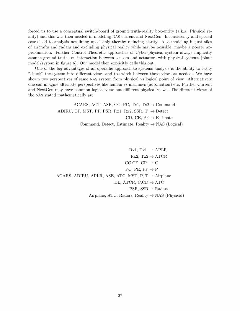
forced us to use a conceptual switch-board of ground truth-reality box-entity (a.k.a. Physical re-ality) and this was then needed in modeling NAS current and NextGen. Inconsistency and specialcases lead to analysis not lining up cleanly thereby reducing clarity. Also modeling in just silosof aircrafts and radars and excluding physical reality while maybe possible, maybe a poorer ap-proximation. Further Control Theoretic approaches of Cyber-physical system always implicitlyassume ground truths on interaction between sensors and actuators with physical systems (plantmodel/system in figure 6). Our model then explicitly calls this out.
One of the big advantages of an operadic approach to systems analysis is the ability to easily”chuck” the system into different views and to switch between these views as needed. We haveshown two perspectives of same NAS system from physical vs logical point of view. Alternativelyone can imagine alternate perspectives like human vs machines (automation) etc. Further Currentand NextGen may have common logical view but different physical views. The different views ofthe NAS stated mathematically are:
ACARS, ACT, ASE, CC, PC, Tx1, Tx2→ Command
ADIRU, CP, MST, PP, PSR, Rx1, Rx2, SSR, T → Detect
CD, CE, PE→ Estimate
Command, Detect, Estimate, Reality→ NAS (Logical)
Rx1, Tx1 → APLR
Rx2, Tx2→ ATCR
CC,CE, CP → C
PC, PE, PP→ P
ACARS, ADIRU, APLR, ASE, ATC, MST, P, T→ Airplane
DL, ATCR, C,CD→ ATC
PSR, SSR→ Radars
Airplane, ATC, Radars, Reality→ NAS (Physical)
27
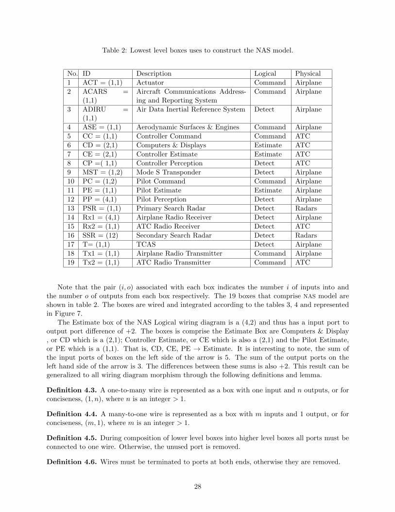
Table 2: Lowest level boxes uses to construct the NAS model.
No. ID Description Logical Physical
1 ACT = (1,1) Actuator Command Airplane
2 ACARS =(1,1)
Aircraft Communications Address-ing and Reporting System
Command Airplane
3 ADIRU =(1,1)
Air Data Inertial Reference System Detect Airplane
4 ASE = (1,1) Aerodynamic Surfaces & Engines Command Airplane
5 CC = (1,1) Controller Command Command ATC
6 CD = (2,1) Computers & Displays Estimate ATC
7 CE = (2,1) Controller Estimate Estimate ATC
8 CP =( 1,1) Controller Perception Detect ATC
9 MST = (1,2) Mode S Transponder Detect Airplane
10 PC = (1,2) Pilot Command Command Airplane
11 PE = (1,1) Pilot Estimate Estimate Airplane
12 PP = (4,1) Pilot Perception Detect Airplane
13 PSR = (1,1) Primary Search Radar Detect Radars
14 Rx1 = (4,1) Airplane Radio Receiver Detect Airplane
15 Rx2 = (1,1) ATC Radio Receiver Detect ATC
16 SSR = (12) Secondary Search Radar Detect Radars
17 T= (1,1) TCAS Detect Airplane
18 Tx1 = (1,1) Airplane Radio Transmitter Command Airplane
19 Tx2 = (1,1) ATC Radio Transmitter Command ATC
Note that the pair (i, o) associated with each box indicates the number i of inputs into andthe number o of outputs from each box respectively. The 19 boxes that comprise NAS model areshown in table 2. The boxes are wired and integrated according to the tables 3, 4 and representedin Figure 7.
The Estimate box of the NAS Logical wiring diagram is a (4,2) and thus has a input port tooutput port difference of +2. The boxes is comprise the Estimate Box are Computers & Display, or CD which is a (2,1); Controller Estimate, or CE which is also a (2,1) and the Pilot Estimate,or PE which is a (1,1). That is, CD, CE, PE → Estimate. It is interesting to note, the sum ofthe input ports of boxes on the left side of the arrow is 5. The sum of the output ports on theleft hand side of the arrow is 3. The differences between these sums is also +2. This result can begeneralized to all wiring diagram morphism through the following definitions and lemma.
Definition 4.3. A one-to-many wire is represented as a box with one input and n outputs, or forconciseness, (1, n), where n is an integer > 1.
Definition 4.4. A many-to-one wire is represented as a box with m inputs and 1 output, or forconciseness, (m, 1), where m is an integer > 1.
Definition 4.5. During composition of lower level boxes into higher level boxes all ports must beconnected to one wire. Otherwise, the unused port is removed.
Definition 4.6. Wires must be terminated to ports at both ends, otherwise they are removed.
28

Fig
ure
7:
(a)T
op:
Wir
ing
Dia
gram
ofth
eL
ogic
alN
AS,
(b)B
otto
m:W
irin
gD
igra
mof
the
Physi
cal
NA
S
29

Table 3: Logical NAS Integration.
No. ID Description
1 Command = (2,3) ACARS =(m,n), ACT=(1,1), ASE=(1,1), CC=(1,1),PC=(1,2), Tx1=(1,1), Tx2=(1,1)
2 Detect = (5,4) ADIRU=(1,1), CP=(1,1), MST=(1,2), PP=(4,1), PSR=(1,1),Rx1=(1,1), Rx2=(1,1), SSR=(1,2), T=(1,1)
3 Estimate = (4,2) CD=(2,1), CE=(2,1), PE=(1,1)
4 Reality = (1,3)
5 NAS Logical = (0,0) Detect=(5,4), Estimate=(4,2), Command=(2,3), Real-ity=(1,3)
Table 4: Physical NAS Integration.
No. ID Description
1 APLR=(2,2) Rx1=(1,1), Tx1=(1,1)
2 ATCR = (2,2) Rx2=(1,1), Tx2=(1,1)
3 C= (2,1) CC(1,1), CE(2,1), CP(1,1)
4 P= (4,2) PC(1,2), PE(1,1), PP(4,1)
5 Airplane = (4,3) ACARS(mn,n), ACT=(1,1), ADIRU=(1,1), ASE=(1,1),MST(1,1), P=(4,2), APLR=(2,2)
6 ATC = (3,1) CD=(2,1), C=(2,1), ATCR=(2,2)
7 Radars = (2,3) PSR=(1,1), SSR=(1,2)
8 Reality = (1,3)
5 NAS Physical =(0,0)
Airplane=(4,3), ATC=(3,1), Radars=(2,3), Reality=(1,3)
30

Definition 4.7. Wiring Rules. Recall from earlier, a wiring diagram is a function from demandto supply: for every demander we assign a supplier. This function is divided into two pieces, eachmapping from demand to supply. Thus a morphism ϕ : A1, ..., Ak → B is a pair of functions
ϕin : A1in t ... tAk in −→ Bin tA1
out t ... tAkout
ϕout : Bout −→ A1out t ... tAkout
Lemma 4.8. Conservation of Port Difference Let A1, ..., Ak → B, where A1 = (m1, n1), ..., Ak =(mk, nk, ), B = (M,N), and m1, ...,mk, n1, ..., nk,M,N are non-negative integers. Then, M −N =∑k
i=1 (mi − ni).
Proof. Let lp represent the the number of wires in Apout that are suppliers to A1
in t ... t Ak in .
Clearly, lp ≤ np ∀p = 1, ..., k and∑k
i=1 li ≤∑k
i=1mi. There are M suppliers from Bin that can
be connected to∑k
i=1(mi − li) demanders of the remaining in A1in t ... t Ak in . Any remaining
suppliers from A1outt ...tAkout,
∑ki=1(ni− li) will connect to the N demanders of Bout . Therefore,
M −N =k∑i=1
(mi − li)−k∑i=1
(ni − li)
=
k∑i=1
(mi − ni)
31
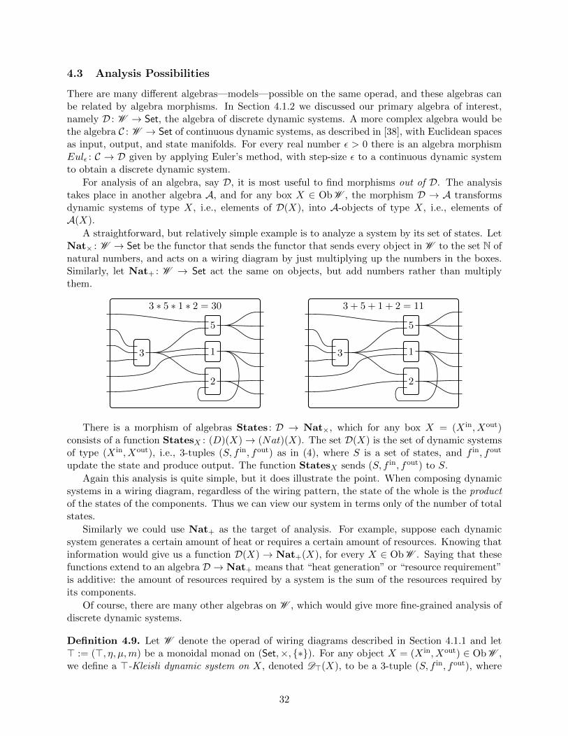
4.3 Analysis Possibilities
There are many different algebras—models—possible on the same operad, and these algebras canbe related by algebra morphisms. In Section 4.1.2 we discussed our primary algebra of interest,namely D : W → Set, the algebra of discrete dynamic systems. A more complex algebra would bethe algebra C : W → Set of continuous dynamic systems, as described in [38], with Euclidean spacesas input, output, and state manifolds. For every real number ε > 0 there is an algebra morphismEulε : C → D given by applying Euler’s method, with step-size ε to a continuous dynamic systemto obtain a discrete dynamic system.
For analysis of an algebra, say D, it is most useful to find morphisms out of D. The analysistakes place in another algebra A, and for any box X ∈ Ob W , the morphism D → A transformsdynamic systems of type X, i.e., elements of D(X), into A-objects of type X, i.e., elements ofA(X).
A straightforward, but relatively simple example is to analyze a system by its set of states. LetNat× : W → Set be the functor that sends the functor that sends every object in W to the set N ofnatural numbers, and acts on a wiring diagram by just multiplying up the numbers in the boxes.Similarly, let Nat+ : W → Set act the same on objects, but add numbers rather than multiplythem.
3
5
1
2
3 ∗ 5 ∗ 1 ∗ 2 = 30
3
5
1
2
3 + 5 + 1 + 2 = 11
There is a morphism of algebras States : D → Nat×, which for any box X = (X in, Xout)consists of a function StatesX : (D)(X)→ (Nat)(X). The set D(X) is the set of dynamic systemsof type (X in, Xout), i.e., 3-tuples (S, f in, fout) as in (4), where S is a set of states, and f in, fout
update the state and produce output. The function StatesX sends (S, f in, fout) to S.
Again this analysis is quite simple, but it does illustrate the point. When composing dynamicsystems in a wiring diagram, regardless of the wiring pattern, the state of the whole is the productof the states of the components. Thus we can view our system in terms only of the number of totalstates.
Similarly we could use Nat+ as the target of analysis. For example, suppose each dynamicsystem generates a certain amount of heat or requires a certain amount of resources. Knowing thatinformation would give us a function D(X) → Nat+(X), for every X ∈ Ob W . Saying that thesefunctions extend to an algebra D → Nat+ means that “heat generation” or “resource requirement”is additive: the amount of resources required by a system is the sum of the resources required byits components.
Of course, there are many other algebras on W , which would give more fine-grained analysis ofdiscrete dynamic systems.
Definition 4.9. Let W denote the operad of wiring diagrams described in Section 4.1.1 and let> := (>, η, µ,m) be a monoidal monad on (Set,×, {∗}). For any object X = (X in, Xout) ∈ Ob W ,we define a >-Kleisli dynamic system on X, denoted D>(X), to be a 3-tuple (S, f in, fout), where
32
S is a set and f in and fout are functions:
f in : X in × S −→ >S (>-Kleisli state update)
fout : S −→ >Xout (>-Kleisli readout)
The composition is given by the usual Kleisli composition. If Y ∈ Ob W is another object and(T, gin, gout) ∈ D>(Y ) is a >-Kleisli dynamic system on Y , then one obtains a >-Kleisli dynamicsystem (
S × T,m(f in × gin),m(fout × gout))
on X t Y using the cartesian product of sets and coherence map m of >. Thus we have defined afunction
D>(X)×D>(Y )→ D>(X t Y ).
Finally, given a morphism ϕ : X → Y in W , define D>(ϕ) : D>(X) → D>(Y ) as in (5), where thecompositions and diagonals are taken in the Kleisli category.
Note that in the case that > = idSet is the initial (monoidal) monad on Set, an idSet-Kleislidynamic system is just a dynamic system in the sense of (4). That is, for any object X ∈ Ob W ,we have DidSet(X) = D(X). This result is strengthened in the following theorem.
Theorem 4.10. Let W denote the operad of wiring diagrams described in Section 4.1.1, letW –Alg denote its category of algebras, and let MndSet denote the category of monoidal monads on(Set,×, {∗}). There is a functor
KlsDyn : MndSet→ W –Alg
which sends a monoidal monad > := (>, η, µ,m) ∈ MndSet to the algebra D> := KlsDyn(top),defined in Definition 4.9.
If 1 ∈ MndSet is the initial monad, i.e., the identity functor, then KlsDyn(1) = D. It followsthat for any cartesian monad >, there is a canonical morphism of algebras
η> : D → D>.
Sketch of proof. Since > is a monoidal monad on Set, the Kleisli category Kls(>) is a monoidalcategory. Moreover, since Set is cartesian monoidal, so is Kls(>). The definition of the dynamicsystems algebra in Theorem 4.2 really only used this Cartesian monoidal structure.
There are many cartesian monads > on Set. The idea is to replace sets and functions with morestructured categories, the Kleisli categories of these monads. For example, suppose that > = P isthe power set monad, so that the Kleisli category is the category of sets and relations (rather thansets and functions). Then the state-update and readout functions in DP, the algebra of relationaldynamic systems, includes two functions:
f in : X in × S → P(S) (state update relation)
fout : S → P(Xout) (readout relation)
These say: given an input and a current state, what is the set of possible next states? Givena current state, what is the set of possible outputs? We call these relations because a functionA→ P(B) is equivalent to a relation R ⊆ A×B.
33

Another cartesian monad is the probability distributions monad, Dist, often called the Girymonad. The Kleisli category for this is Markov processes. The state-update and readout functionsin DDist, the algebra of Markov dynamic systems, includes two functions:
f in : X in × S → Dist(S) (Markovian state update)
fout : S → Dist(Xout) (Markovian relation)
It is readily seen that these are hidden Markov models.As mentioned in Conjecture 4.10, there is a morphism of algebras D → D> for any such
monoidal monad > on Set. These are analysis tools that can use sampling, possibility analysis, etc.Beyond Kleisli dynamic systems, other targets for analysis are certainly possible. Above, we
mentioned a couple very simple ones, Nat+ and Nat×, and there are many more. To reiterate,the only requirement of a potential analysis target A is that it should obey the laws for being aW -algebra, and that there should be an algebra morphism D → A.
34

5 Final Remarks
5.1 Conclusions
Category Theory (CT) based operadic framework appears to be quite promising towards evaluationof current and NextGen National Airspace (NAS). On the whole, the approach helps system inte-grator with easier identification of re-usable design patterns helps reduce development and V&V(verification and validation) time/costs. It also provides a rigorous mathematical foundation forbuilding safety assurance claims. The framework is also quite conducive to creating a collaborativeknowledge space amongst engineers, system architects, and regulatory authorities with varying skillsets and competence in handling mathematics. Mathematical rigor and formalism is maintained,but gets out of the way, as long as minimal set of rules and constraints are respected during themodeling process.
Our exploration of CT in this project has also revealed many modeling benefits. The designershave the ability to use alternative abstractions for analyzing systems by providing different waysto chunk the models (e.g. logical vs physical view) and simultaneously nest and zoom withinthe models for different decompositions of abstractions (e.g. coarse-grained vs fine-grained modelfidelity), as shown in Figure 7.
CT also seems to be a perfect fit for incremental model specifications and refinements whichas explained in section 2.3 is the likely transition scenarios in NextGen. For example, it allows thesystem designer to specify and analyze the whole system even when the details of a particularsub-system is not known at that point in the design life cycle (maybe because technology detailsnot available at a point in time). In this situation, model can be specified at a box level forthat sub-system with desired inputs & outputs in a black-box fashion. The sub-system can thensubsequently be refined and specified later in the design life cycle and as long as the refined designstill adheres to the original input/output constraints, the original analysis continues to hold.
Finally, CT also offers many analysis benefits. It provides the much desired compositionalanalysis over all the typical modeling operations above (e.g. zooming, nesting, chunking, etc). Italso naturally offers possibilities for compositional summaries: a morphism of algebras providessummary statistics that can be combined with others. Averages are not operadic because “theaverage of averages is not the average”. In contrast, Weighted Averages are operadic. That is,a good summary has the property that it can be used in conjunction with other summaries; thiscompositionality is what the operadic formalism ensures.
5.2 Future Work
In the second phase of this project, we will explore several issues, which have not yet addressed.These include allowing each component subsystem to have its own clock, modeling hierarchical faultpropagation and failure analysis in a system of systems, and providing a higher-level descriptionlanguage for specifying subsystems, as necessary for governmental regulation.
In the above work, each system is modeled as a discrete dynamical system. When these systemsare put together into a bigger system, it was assumed that the clock ticks of each system wererepresenting the same time-scale. This is certainly not something we want to force on modelers ofcomponents. In particular, by modeling independent clocks of sub-system (notion of time), we thenhave a way to handle channel/information delay and also possibly a way to handle both discreteand continuous dynamical system in the same model. This issue can be dealt with in a numberof ways, but we will need to make a choice between them. This requires a detailed back-and-forthbetween domain experts (Honeywell) and mathematical modelers (MIT). Inability to handle this
35

tricky ”time” issue within the dynamical system model has hindered characterizing many NationalAirspace (NAS) boxes/components listed in section 4.2. We hope to remedy this in the next phase.
A critical issue for the NAS is to understand and limit failure. To this end, we will consider howfailures propagate through a system of systems. Our work is inherently hierarchical, which meanswe cannot consider approaches to fault modeling that assume a closed world. For example, wecannot assume that there are only a small number, say two, faults throughout the system becausecomposing two such systems violates the assumption immediately.
Instead, our plan is to consider the kind of fault propagation that does nest in a compatible way.For example, each component system could have a partial order of failure modes. Suppose for thesake of discussion that this partial order consists of two elements, normal and fail. A given system’sfailure mode can be influenced by upstream systems. That is, if systems A, B1, and B2 are sendinginformation to C, perhaps C fails if either A or both B1 and B2 fails. In this way, failures cascadethrough the system, and it is important to understand the extent of this cascade, the eventualsteady state of failure modes that arise. We plan to consider this kind of failure analysis, which(from our current vantage point) appears to be well-behaved under hierarchical composition, tostudy the cascading effects of stochastic failures.
Typically, individual System suppliers, individual Component Vendors and Aircraft OriginalEquipment Manufacturers (OEMs) all provide both detailed low-level and a coarse-grained high-levelrequirements and design specifications of their products. Administrative authorities (e.g FederalAviation Administration (FAA)) use these requirements and specification to first regulate, manageand finally certify those systems. Just being provided the dynamical systems view of components(i.e. low-level requirements and/or specification) is not one that can be easily regulated or overseenby certifying authorities. The reason is that to define a dynamical system involves providing acomplete list of its internal states as well as a formula for its behavior for each specific input andinternal state. While designers may have such intimate knowledge, it is harder for the oversightentities to have such detailed insights and familiarity.
In order to simplify their task further, authorities additionally prefer to be given behavioralbounds (i.e. high-level requrements and/or specification), classifying the states, inputs, and outputsinto a manageable number of classes, specifying that when the state and input are in class X,the output will be in class Y. This can be modeled as a non-deterministic dynamical system.As an analogy, runtime complexity or memory/storage capacity of a software code is typicallycharacterized in terms of best-case/average-case/worst-case (behavioral) asymptotic bounds in thenotation o(F1(n))/Θ(F2(n))/O(F3(n)) where Fi are some functions and n indicates size of the inputto the software. It is easy to see that managing and regulating behavioral bound is much easierthan actual software code/specification.
We plan to consider how to relate deterministic (fully specified) dynamical systems and thesenondeterministic dynamical systems, and to show that there is an algebraic mapping between them.In other words, we will attempt to give a formula for composing behaviorally-specified dynamicalsystems of systems, thus giving another algebra for our operad, and then show that there is amorphism from the fully-specified algebra to the behaviorally-specified one.
36

6 SOW Checklist
SCOPE OF WORKThe scope of this task is to develop and evaluate innovative techniques from the mathematical
field of Category Theory (CT) as a framework to evaluate the overall performance of a System-of-Systems (SoS) as applied to distributed systems in the airspace. The Contractor shall develop acategory-theoretic framework to analyze and assess safety of NextGen capabilities from a distributedsystems perspective. The Contractor shall address automated aircraft separation using the existingcommunication channels defined for NextGen and supporting all planned meetings, reviews, andpresentations identified in Section 4.0.
Table 5: SOW Cross Reference
ID Requirement Addressed
3.1.1 Collect and define terms for expressing safety and invariants ofsystems-of-systems in an airspace context.
Chapter 2.1, 2.2
3.1.2 Formalize the terms and invariants using category-theoretic struc-tures of airspace safety properties and assessment methods suchas those found in Aerospace Recommended Practice (ARP) 4761.This information shall be reported in a NASA Contractor Report(CR) on the formalization of terms and definitions (DeliverableItem 3).
This Document -Operadic Analy-sis of DistributedSystems
3.1.3 Apply multicategorical structures (aka Operads) to create a frame-work for expressing and reasoning about safety properties ofsystems-of-systems in an airspace context.
Chapter 4
3.1. 4 Apply the category-theoretic framework to notional or real-worldexamples of the NextGen airspace. For instance, apply the frame-work to a case study comprising an airspace of NextGen commu-nication nodes with a safe separation invariant.
Chapter 4.3
3.1.5 Evaluate the efficacy of the category-theoretic framework in com-parison to the existing techniques for evaluating invariant proper-ties of systems-of-systems.
Chapter1.2,1.3,5.1
3.1.6 Develop and integrate category-theoretic methods that assess howcredible faults, disturbances, and degradations adversely impactsafety, focusing initially on distributed NextGen Flight CriticalSystems (FCS) providing data that supports automated aircraftseparation.
Chapter 5.2
3.1.7 At the conclusion of the base period of performance, conduct abriefing that summarizes all activities (describing the results andlessons learned). This shall be the basis for determining if the Con-tracting Officer will provide authorization to proceed into PhaseII by incrementally funding the contract (Deliverable Item 4 ).3.1.8 Provide an Annual Report summarizes the findings in PhaseI (Deliverable Item 5).
Final Meeting @LaRC
37

References
1. Boeing: Statistical Summary of Commercial Jet Airplane Accidents, Worldwide Operations,1959-2013. 2014. URL http://www.boeing.com/news/techissues/pdf/statsum.pdf, [On-line; accessed 2015/03/06].
2. NASA, Langley Formal Methods: Airborne Coordinated Conflict Resolution and Detection.URL http://shemesh.larc.nasa.gov/people/cam/ACCoRD/, [Online; accessed 2015/03/18].
3. NASA, Langley Formal Methods: PVS Libary. URL http://shemesh.larc.nasa.gov/fm/
ftp/larc/PVS-library/pvslib.html, [Online; accessed 2015/03/18].
4. Feiler, P. H.; Gluch, D. P.; and Hudak, J. J.: The architecture analysis & design language(AADL): An introduction. , DTIC Document, 2006.
5. Debruyne, V.; Simonot-Lion, F.; and Trinquet, Y.: EAST-ADLAn architecture descriptionlanguage. Architecture Description Languages, Springer, 2005, pp. 181–195.
6. Friedenthal, S.; Moore, A.; and Steiner, R.: A practical guide to SysML: the systems modelinglanguage. Access Online via Elsevier, 2011.
7. Graves, H.; and Bijan, Y.: Using Formal Methods with SysML in Aerospace Design andEngineering. Annals of Mathematics and Artificial Intelligence, vol. 63, no. 1, Sept. 2011,pp. 53–102. URL http://dx.doi.org/10.1007/s10472-011-9267-5.
8. SRI International: SAL - Symbolic Analysis Laboratory. URL http://sal.csl.sri.com/
introduction.shtml, [Online; accessed 2015/03/18].
9. Bengtsson, J.; Larsen, K.; Larsson, F.; Pettersson, P.; and Yi, W.: UPPAALa tool suite forautomatic verification of real-time systems. Springer, 1996.
10. University of Iowa: KIND2 - Multi-engine SMT-based automatic model checker for safetyproperties of Lustre programs. URL https://github.com/kind2-mcl, [Online; accessed2015/03/18].
11. Kwiatkowska, M.; Norman, G.; and Parker, D.: PRISM 4.0: Verification of Probabilistic Real-time Systems. Proc. 23rd International Conference on Computer Aided Verification (CAV’11),G. Gopalakrishnan and S. Qadeer, eds., Springer, vol. 6806 of LNCS , 2011, pp. 585–591.
12. Umeno, S.; and Lynch, N.: Proving safety properties of an aircraft landing protocol using I/Oautomata and the PVS theorem prover: A case study. FM 2006: Formal Methods, Springer,2006, pp. 64–80.
13. Institut National de Recherche en Informatique et en Automatique: The Coq Proof Assistant.URL https://coq.inria.fr/, [Online; accessed 2015/03/18].
14. Shelley, G.; and Forrest, S.: ACL2 Theorem Prover.
15. Paulson, L. C.: Isabelle: The next 700 theorem provers. Logic and computer science, vol. 31,1990, pp. 361–386.
16. Vagner, D.; Spivak, D. I.; and Lerman, E.: Algebras of Open Dynamical Systems on the Operadof Wiring Diagrams. arXiv preprint arXiv:1408.1598 , 2014.
38

17. Federal Aviation Administration (FAA): Administration Order JO 7110.65U, Air Traffic Con-trol, and the Briefing Guide, 2013.
18. Dillingham, G. L.; Wilshusen, G. C.; and Barkakati, N.: Air Traffic Control GAO 15-370Report: FAA Needs a More Comprehensive Approach to Address Cybersecurity As AgencyTransitions to NextGen. , April 14 2015.
19. Federal Aviation Administration: The Economic Impact of Civil Aviation on theU.S. Economy. 2014. URL https://www.faa.gov/air_traffic/publications/media/
2014-economic-impact-report.pdf, [Online; accessed 2015/03/05].
20. Federal Aviation Administration: Order JO 7400.2K, Part 4. Terminal and En Route Airspace,Chapter 14. Designation of Airspace Classes. 2014. URL https://www.faa.gov/air_traffic/
publications/atpubs/AIR/air1401.html, [Online; accessed 2015/03/05].
21. National Air Traffic Controllers Association: A History of Air Traffic Control.2010. URL http://www.natca.org/ULWSiteResources/natcaweb/Resources/file/Media%
20Center/ATCHistory.pdf, [Online; accessed 2015/03/07].
22. International Civil Aviation Organization: Doc 4444 Procedures for Air Navigation Ser-vices - Air Traffic Management. 2007. URL https://apcae.files.wordpress.com/2009/05/
doc-4444.pdf, [Online; accessed 2015/03/09].
23. FAA: NextGen Programs. URL http://www.faa.gov/nextgen/programs/.
24. FAA: Automatic Dependent Surveillance-Broadcast (ADS-B). URL http://www.faa.gov/
nextgen/implementation/programs/adsb/.
25. FAA: Traffic Information Services Broadcast (TIS-B). URL http://www.faa.gov/air_
traffic/publications/atpubs/aim/aim0405.html.
26. FAA: ControllerPilot Data Link Communications (CPDLC). URL http://www.skybrary.
aero/index.php/Controller_Pilot_Data_Link_Communications_(CPDLC).
27. Giesa, T.; Jagadeesan, R.; Spivak, D. I.; and Buehler, M. J.: Matriarch: A python library formaterials architecture. ACS Biomaterials, 2015.
28. Spivak, D. I.; Giesa, T.; Wood, E.; and Buehler, M. J.: Category Theoretic Analysis ofHierarchical Protein Materials and Social Networks. PLoS ONE , vol. 6, no. 9, Septem-ber 2011. Available online: http://journals.plos.org/plosone/article?id=10.1371/
journal.pone.0023911.
29. Giesa, T.; Spivak, D. I.; and Buehler, M. J.: Reoccurring patterns in hierarchical proteinmaterials and music: the power of analogies. BioNanoScience, vol. 1.4, 2011.
30. Brown, R.; and Porter, T.: Category Theory: an abstract setting for analogy and comparison.What is category theory, Volume 3 , Polimetrica, 2006, pp. 257 – 274.
31. Burstall, R. M.; and Goguen, J.: Putting theories together to make specifications. Proceedingsof the 5th international joint conference on Artificial intelligence, vol. 2, 1977.
32. Williamson, K.; Healy, M.; and Barker, R.: Industrial Applications of Software Synthesis viaCategory TheoryCase Studies Using Specware. Automated Software Engineering , vol. 8, 2001.
39

33. Spivak, D. I.; and Kent, R. E.: Ologs: A Categorical Framework for Knowledge Representation.PLoS ONE , January 2012. Available online: http://journals.plos.org/plosone/article?id=10.1371/journal.pone.0024274.
34. Leinster, T.: Higher operads, higher categories, vol. 298 of London Mathematical Society LectureNote Series. Cambridge University Press, Cambridge, 2004. URL http://dx.doi.org/10.
1017/CBO9780511525896.
35. Spivak, D. I.: Category theory for the sciences. MIT Press, 2014.
36. Spivak, D. I.: The operad of wiring diagrams: formalizing a graphical language for databases,recursion, and plug-and-play circuits, 2013. Available online: http://arxiv.org/abs/1305.
0297.
37. Ellis, T.: Opaleye. GitHub repository. Open-source Haskell library, available online: https:
//github.com/tomjaguarpaw/haskell-opaleye.
38. Vagner, D.; Spivak, D. I.; and Lerman, E.: Algebras of Open Dynamical Systems on the Operadof Wiring Diagrams, 2014. Available online: http://arxiv.org/abs/1408.1598.
39. Spivak, D. I.: Nesting of dynamic systems and mode-dependent networks. 2015. Availableonline: http://arxiv.org/abs/1502.07380.
40. Willems, J. C.: The behavioral approach to open and interconnected systems. IEEE controlsystems magazine, 2007, pp. 46–99.
41. Wikipedia: Control theory — Wikipedia, The Free Encyclopedia. 2015. URL https://en.
wikipedia.org/wiki/Control_theory, [Online; accessed 2015/03/01].
40
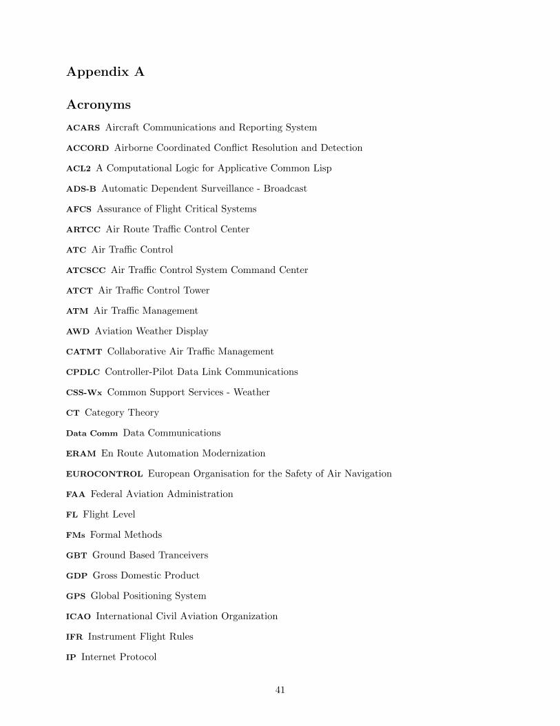
Appendix A
Acronyms
ACARS Aircraft Communications and Reporting System
ACCORD Airborne Coordinated Conflict Resolution and Detection
ACL2 A Computational Logic for Applicative Common Lisp
ADS-B Automatic Dependent Surveillance - Broadcast
AFCS Assurance of Flight Critical Systems
ARTCC Air Route Traffic Control Center
ATC Air Traffic Control
ATCSCC Air Traffic Control System Command Center
ATCT Air Traffic Control Tower
ATM Air Traffic Management
AWD Aviation Weather Display
CATMT Collaborative Air Traffic Management
CPDLC Controller-Pilot Data Link Communications
CSS-Wx Common Support Services - Weather
CT Category Theory
Data Comm Data Communications
ERAM En Route Automation Modernization
EUROCONTROL European Organisation for the Safety of Air Navigation
FAA Federal Aviation Administration
FL Flight Level
FMs Formal Methods
GBT Ground Based Tranceivers
GDP Gross Domestic Product
GPS Global Positioning System
ICAO International Civil Aviation Organization
IFR Instrument Flight Rules
IP Internet Protocol
41

IMC Instrument Meteorological Conditions
MBSE Model Based Systems Engineering
MSL Mean Sea Level
NAS National Airspace
NASA National Aeronautics and Space Administration
NAVAIDS Navigational Aids
NextGen Next Generation Air Transport System
NM Nautical Miles
NVS NAS Voice Switch
NWP NextGen Weather Processor
OEMs Original Equipment Manufacturers
PRISM Probabilistic Model Checker
PSR Primary Search Radar
PVS Prototype Verification System
ROA Research Opportunities in Aeronautics
RVSM Reduced Vertical Separation Minima
SA Situational Awareness
SAL Symbolic Analysis Laboratory
SBSS Surveillance and Broadcast Services Subsystem
SESAR Single European Sky ATM Research
SM Statute Miles
SoS System of Systems
SSAT System-wide Safety and Assurance Technologies
SSR Secondary Search Radar
SWIM System Wide Information Management
TRACON Terminal Radar Approach Control
TIS-B Traffic Information Services Broadcast
TCAS II Traffic Collision Avoidance System
UAT Universal Access Transceiver
42

VFR Visual Flight Rules
VMC Visual Meteorological Conditions
1090 ES 1090 MHz Extended Squitter
43
REPORT DOCUMENTATION PAGE Form ApprovedOMB No. 0704–0188
The public reporting burden for this collection of information is estimated to average 1 hour per response, including the time for reviewing instructions, searching existing data sources,gathering and maintaining the data needed, and completing and reviewing the collection of information. Send comments regarding this burden estimate or any other aspect of this collectionof information, including suggestions for reducing this burden, to Department of Defense, Washington Headquarters Services, Directorate for Information Operations and Reports(0704-0188), 1215 Jefferson Davis Highway, Suite 1204, Arlington, VA 22202-4302. Respondents should be aware that notwithstanding any other provision of law, no person shall besubject to any penalty for failing to comply with a collection of information if it does not display a currently valid OMB control number.PLEASE DO NOT RETURN YOUR FORM TO THE ABOVE ADDRESS.
Standard Form 298 (Rev. 8/98)Prescribed by ANSI Std. Z39.18
1. REPORT DATE (DD-MM-YYYY)01-09-2015
2. REPORT TYPEContractor Report
3. DATES COVERED (From - To)
10/2014-9/20154. TITLE AND SUBTITLE
Operadic Analysis of Distributed Systems
5a. CONTRACT NUMBERNNL14AA05C
5b. GRANT NUMBER
5c. PROGRAM ELEMENT NUMBER
5d. PROJECT NUMBER
5e. TASK NUMBER
5f. WORK UNIT NUMBER
6. AUTHOR(S)
Kevin Schweiker, Srivatsan Varadarajan, David Spivak, Patrick Schultz
7. PERFORMING ORGANIZATION NAME(S) AND ADDRESS(ES)
NASA Langley Research CenterHampton, Virginia 23681-2199
8. PERFORMING ORGANIZATIONREPORT NUMBER
L–yyyyyy
9. SPONSORING/MONITORING AGENCY NAME(S) AND ADDRESS(ES)
National Aeronautics and Space AdministrationWashington, DC 20546-0001
10. SPONSOR/MONITOR’S ACRONYM(S)NASA
11. SPONSOR/MONITOR’S REPORTNUMBER(S)
NASA/CR–2015–xxxxxx
12. DISTRIBUTION/AVAILABILITY STATEMENT
Unclassified-UnlimitedSubject Category 62Availability: NASA CASI (443) 757-5802
13. SUPPLEMENTARY NOTES
An electronic version can be found at http://ntrs.nasa.gov.Technical Monitor: Alwyn Goodloe
14. ABSTRACT
Establishing an assurance claim for a distributed safety critical system has proven extremely difficult. Developing anddocumenting the evidence needed to support a claim requires diverse models and abstractions of system properties to capturebehaviors, understand error propagation, and evaluate the interactions with other systems and humans. The ability to scaleand merge these diverse models and abstractions within a sound mathematical framework is the subject of this technicalreport. Category theory is one promising approach for this mathematical framework. A higher category theory known asoperad theory is described and used to evaluate the effects of disruptions and failures of NextGen communication channels onthe safe separation of aircraft within the National Airspace (NAS).
15. SUBJECT TERMS
Category Theory, Distributed Systems, National Air Space, NextGen
16. SECURITY CLASSIFICATION OF:
a. REPORT
U
b. ABSTRACT
U
c. THIS PAGE
U
17. LIMITATION OFABSTRACT
UU
18. NUMBEROFPAGES
50
19a. NAME OF RESPONSIBLE PERSON
STI Help Desk (email: [email protected])
19b. TELEPHONE NUMBER (Include area code)
(443) 757-5802

