operating and installation instructions ventilation … and installation instructions ventilation...
TRANSCRIPT

Operating and Installation InstructionsVentilation Hood
To prevent accidents and damage to the appliance, you must readthese instructions before installing the appliance and using it for the firsttime.
en-US M.-Nr. 10 597 860

Contents
2
IMPORTANT SAFETY INSTRUCTIONS ................................................................ 3
Caring for the environment ................................................................................ 12
Description of functions ..................................................................................... 13
Guide to the appliance ........................................................................................ 14
Operation.............................................................................................................. 16Turning on the blower............................................................................................ 16Selecting the power level ...................................................................................... 16Turning off the blower............................................................................................ 17Turning the overhead lighting on/off...................................................................... 17Safety switch-off ................................................................................................... 17
Cleaning and care ............................................................................................... 18Stainless steel housing.......................................................................................... 18Grease filters ......................................................................................................... 19OdorFree Charcoal Filter ....................................................................................... 21Changing a light bulb ............................................................................................ 22
Installation............................................................................................................ 23Before installation.................................................................................................. 23Removing the protective film................................................................................. 23Installation Instructions ......................................................................................... 23Disassembly .......................................................................................................... 23Installation parts .................................................................................................... 24Appliance dimensions ........................................................................................... 26Distance between cooktop and ventilation hood (S)............................................. 27Installation recommendations ............................................................................... 28Drilling diagram for wall mounting......................................................................... 28Plywood backing .................................................................................................. 29To install a plywood backing ................................................................................ 29
Air venting ............................................................................................................ 30Condensate trap.................................................................................................... 31Reducing Collar .................................................................................................... 31
Electrical connection .......................................................................................... 32
Service and warranty .......................................................................................... 33Location of the data plate ..................................................................................... 33MieleCare .............................................................................................................. 33
Technical data ..................................................................................................... 34

IMPORTANT SAFETY INSTRUCTIONS
3
READ AND SAVE THESE INSTRUCTIONS
This appliance complies with current safety requirements.Improper use of the appliance can lead to personal injury andmaterial damage.
Read all instructions before installing or using the appliance for thefirst time. Only use the appliance for its intended purpose.
Keep these operating instructions in a safe place and pass themon to any future user.
Use
CAUTION: For General Ventilating Use Only. Do Not Use ToExhaust Hazardous Or Explosive Materials And Vapors.
This appliance is intended for residential use only. Use only asdescribed in these operating instructions.
This ventilation hood is not intended for outdoor use.
It must only be used to extract and clean vapors produced duringcooking. Any other use occurs at the owner's own risk.
This appliance is suitable for installation above gas or electriccooking surfaces.
Persons who lack physical, sensory or mental abilities, orexperience with the appliance should not use it without supervisionor instruction by a responsible person.

IMPORTANT SAFETY INSTRUCTIONS
4
Children
As with any appliance, close supervision is necessary when usedby children.
Please supervise children in the vicinity of the hood and do not letthem play with it.
The LED ClearView lighting is very intense.Ensure that especially babies/small children don't look into the light.
Danger of suffocation! Ensure that any plastic wrappings, bags,etc. are disposed of safely and kept out of the reach of children.
Technical safety
WARNING: TO REDUCE THE RISK OF FIRE, ELECTRIC SHOCK,OR INJURY TO PERSONS, OBSERVE THE FOLLOWING:
– Use this appliance only in the manner intended by themanufacturer. If you have questions, contact Miele.
– Before servicing or cleaning the appliance, switch power off at theservice panel and lock the service disconnecting means toprevent power from being switched on accidentally. If the servicedisconnecting means cannot be locked, securely fasten aprominent warning device, such as a tag, to the service panel.
Installation, repair and maintenance work should be performed bya Miele authorized service technician in accordance with nationaland local safety regulations and the provided installationinstructions. Contact Miele’s Technical Service Department forexamination, repair or adjustment. Repairs and other work byunauthorized persons could be dangerous and may void thewarranty.
A damaged ventilation hood can be dangerous. Always check forvisible signs of damage. Never use a damaged ventilation hood.

IMPORTANT SAFETY INSTRUCTIONS
5
Be certain your appliance is properly installed and grounded by aqualified technician. To guarantee the electrical safety of thisappliance, continuity must exist between the appliance and aneffective grounding system. It is imperative that this basic safetyrequirement be met. If there is any doubt, have the electrical systemof the house checked by a qualified electrician.
Reliable and safe operation of this hood can only be guaranteed ifit has been connected to the electrical supply.
To avoid damaging the ventilation hood, make sure that theconnection data (voltage and frequency) on the data platecorrespond to the building's power supply before connecting theappliance. When in doubt, consult a qualified electrician.
Do not use a power bar or extension cord to connect theventilation hood to electricity. These are a fire hazard and do notguarantee the required level of appliance safety.
To ensure safe operation, only use the ventilation hood after it hasbeen properly installed.
This ventilation hood may not be used in non-stationary locations(e.g. on a ship).
Adequate ventilation must be provided when the hood is operatedsimultaneously with devices that burn gas or other fuels.
Only open the housing as described in the enclosed "Installationdiagram" and in the "Cleaning and care" section of this manual.Under no circumstances should any other parts of the housing beopened.Tampering with electrical connections or components andmechanical parts is highly dangerous to the user and can causeoperation faults.
Defective components should be replaced by Miele original partsonly. Only with these parts can the manufacturer guarantee thesafety of the appliance.

IMPORTANT SAFETY INSTRUCTIONS
6
If the power cord is damaged, it must only be replaced by aqualified service technician.
During installation, maintenance, and repair work, the ventilationhood must be disconnected from the electrical supply. It is onlycompletely isolated from the electricity supply if one of the followingapplies:
– The circuit breakers on the electrical service panel are tripped.
– The screw-type fuses on the electrical service panel have beenremoved.
– The power cable (if present) has been unplugged from the socket(pull the plug not the cord).
Proper use
WARNING: TO REDUCE THE RISK OF A COOKTOP GREASEFIRE:
– a) Never leave surface units unattended at high settings. Boiloverscause smoking and greasy spillovers may ignite. Heat oils slowlyon low or medium settings.
– b) Always turn the hood on when cooking at a high heat.
– c) Clean the ventilation hood frequently. Grease should not beallowed to accumulate on the fan or filter.
– d) Use the proper pan size. Always use cookware appropriate forthe size of the cooking area.
Never use an open flame beneath the ventilation hood.To avoid the risk of fire, do not flambé or grill over an open flame.When turned on, the ventilation hood will draw any flames into thefilter. Fat deposits may ignite.
WARNING: TO REDUCE THE RISK OF INJURY TO PERSONS INTHE EVENT OF A COOKTOP GREASE FIRE, OBSERVE THEFOLLOWING*:

IMPORTANT SAFETY INSTRUCTIONS
7
– a) SMOTHER FLAMES with a close fitting lid, cookie sheet, ormetal tray then turn off the burner. BE CAREFUL TO PREVENTBURNS. If the flames do not go out immediately, EVACUATE ANDCALL THE FIRE DEPARTMENT.
– b) NEVER PICK UP A FLAMING PAN - You may be burned.
– c) DO NOT USE WATER, including wet dishcloths or towels - aviolent steam explosion will result.
– d) Use a fire extinguisher ONLY if:– 1) You have a class ABC extinguisher, and you know how to operate it.
– 2) The fire is small and contained in the area where it started.
– 3) The fire department is being called.
– 4) You can fight the fire with your back to an exit.
*Based on "Kitchen Fire Safety Tips" published by NFPA.
The ventilation hood may become damaged if exposed toexcessive heat from a gas cooktop.
– When using the ventilation hood over a gas cooktop, ensure thatany burners in use are always covered by cookware. Turn burnersoff when removing the cookware, even if doing so for just a shorttime.
– Select cookware that is suitable for the size of the burner.
– Adjust the flame so that it never extends up the sides of thecookware.
– Avoid overheating the cookware (e.g., when cooking with a wok).
Always turn the ventilation hood on whenever a burner is in use toprevent damage from condensation.
Overheated oils and fats can ignite and set the ventilation hood onfire.When cooking with oils or fats, do not leave pots, pans or fryersunattended. Never leave an electric grill unattended when grilling.

IMPORTANT SAFETY INSTRUCTIONS
8
Fat and debris deposits impair the proper functioning of theventilation hood.To ensure that cooking vapors are properly cleaned, never use theventilation hood without the grease filters in place.
There is a risk of fire if cleaning is not completed according to theinstructions in this manual.
Please note that the heat rising from the stovetop during cookingcan cause the ventilation hood to become very hot.Do not touch the housing or the grease filters until the ventilationhood has cooled down.

IMPORTANT SAFETY INSTRUCTIONS
9
Proper installation
WARNING: TO REDUCE THE RISK OF FIRE, ELECTRIC SHOCK,OR INJURY TO PERSONS, OBSERVE THE FOLLOWING:
– a) Installation work and electrical wiring must be done by qualifiedperson(s) in accordance with all applicable codes and standards,including fire-rated construction.
– b) Sufficient air is needed for combustion and exhausting of gasesthrough the flue (chimney of fuel burning equipment to preventback drafting. Follow the heating equipment manufacturer’sguideline and safety standards such as those published by theNational Fire Protection Association (NFPA) and the AmericanSociety for Heating, Refrigeration and Air Conditioning Engineers(ASHRAE), and the local code authorities.
– c) When cutting or drilling into the wall or ceiling, do not damageelectrical wiring and other hidden utilities.
– d) Ducted hoods must always be vented to the outdoors.
– e) Do not use this hood with any solid-state speed control device.
To determine whether a ventilation hood may be operated aboveyour cooking appliance, please refer to the information provided bythe appliance's manufacturer.
Safety regulations prohibit the installation of a ventilation hoodabove solid fuel stoves.
Insufficient distance between the cooking appliance and theventilation hood can result in damage to the hood.The minimum safety distances between the appliance and thebottom of the ventilation hood specified in the "Installation" sectionmust be maintained, unless the appliance's manufacturer hasindicated that a greater distance is required.If more than one cooking appliance is used beneath the ventilationhood, and if different minimum safety distances apply for theseappliances, you should use the greater distance.

IMPORTANT SAFETY INSTRUCTIONS
10
Be sure to observe the information contained in the "Installation"section when mounting the ventilation hood.
Metal parts can have sharp edges which may cause injury.Wear gloves to protect your hands from being cut.
When installing the exhaust duct, only use pipes or tubes made ofnon-flammable material. These can be obtained from your Mieledealer or from Miele Technical Service.
Exhaust air should not be vented into a chimney or vent flue whichis otherwise in use and should not be channeled into ducting whichventilates rooms with fuel-burning installations.
If exhaust air is to be extracted into a chimney or vent flue nolonger used for other purposes, be sure to comply with all applicableregulations.
WARNING: TO REDUCE THE RISK OF FIRE USE ONLY METALDUCTWORK.

IMPORTANT SAFETY INSTRUCTIONS
11
Cleaning and care
Never use a steam cleaner to clean the ventilation hood.The steam can reach the electrical components and cause a shortcircuit.
Accessories
Use only genuine original Miele parts. If parts or accessories fromother manufacturers are used, the warranty will become void.
Caring for the environment
12
Disposal of the packingmaterialThe cardboard box and packingmaterials protect the appliance duringshipping. They have been designed tobe biodegradable and recyclable.
Ensure that any plastic wrappings,bags, etc. are disposed of safely andkept out of the reach of children.Danger of suffocation!
Disposal of your old applianceElectrical and electronic appliancescontain valuable materials. They alsocontain certain substances, compoundsand components which were essentialfor the proper functioning and safe useof the equipment. Handling thesematerials improperly by disposing ofthem in your household waste can beharmful to your health and theenvironment. Therefore, please do notdispose of your old appliance withregular household waste and followlocal regulations on proper disposal.
Consult with local authorities, dealers orMiele in order to dispose of and recycleelectrical and electronic appliances.Miele assumes no responsibility fordeleting any personal data left on theappliance being disposed. Pleaseensure that your old appliance is keptaway from children until removal.Observe safety requirements forappliances that may tip over or pose anentrapment hazard.

Description of functions
13
The following functions are available onyour ventilation hood, depending on themodel:
Vented mode
The air is drawn in and cleaned by thegrease filters and directed outside.
Non-return flap
A non-return flap in the ductingprevents the exchange of inside andoutside air from occurring when theventilation hood is not in use.The flap is closed when the ventilationhood is turned off.When the ventilation hood is turned on,the non-return flap opens so that theexhaust air can be transported outsidewithout any obstruction.
A non-return flap has been providedwith the hood in case your ducting doesnot have one. It is inserted into theoutlet duct collar of the fan.
Recirculation modeThe recirculation mode requires arecirculation kit and OdorFree CharcoalFilter (available as optional accessories,see "Technical Data" for moreinformation)
The air is drawn in and first cleaned bythe grease filters and then by anOdorFree Charcoal Filter. The cleanedair is then recirculated back into thekitchen.

Guide to the appliance
14
Guide to the appliance
15
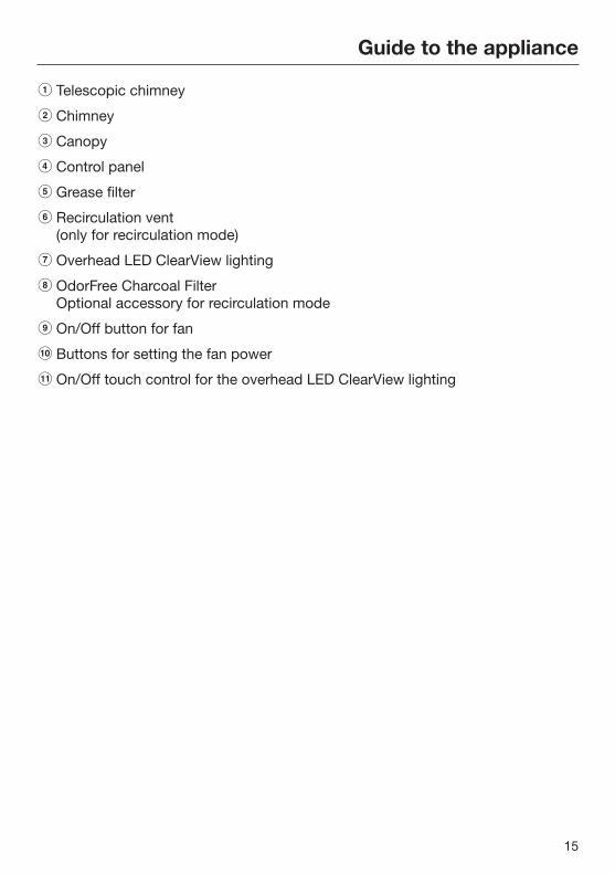
a Telescopic chimney
b Chimney
c Canopy
d Control panel
e Grease filter
f Recirculation vent(only for recirculation mode)
g Overhead LED ClearView lighting
h OdorFree Charcoal FilterOptional accessory for recirculation mode
i On/Off button for fan
j Buttons for setting the fan power
k On/Off touch control for the overhead LED ClearView lighting

Operation
16
Turning on the blower Press the On/Off button .
The blower turns on at level 2. The symbol and 2 will light up in the blowerlevel display.
Selecting the power levelPower levels 1 to 3 can be used for lightto heavy cooking vapors and odors.
For strong vapors and odors that aretemporarily produced when cooking,e.g., during searing, select the Bbooster level.
Press the "" button for a lowerpower level or the "" button toselect a higher level.
Automatic Booster settingswitch-offYou have the option to program thebooster level to ensure the fan willalways switch back to level 3automatically after 10 minutes.
To do this, turn off the fan and theoverhead lighting first.
Press the and buttons at thesame time for approx. 10 seconds,until 1 lights up.
Then, press the following buttons inorder:
– the lighting button ,
– Followed by the button and then
– the lighting button again.
If automatic switch-off is not activated,the 1 and IS displays will flash.
To activate it, press the button.
If 1 and B are lit, automatic switch-off isactivated.
To deactivate it, press the button.
Use the On/Off button to confirmyour choice of setting.If you do not confirm within 4minutes, the system will revert to theold setting.

Operation
17
Turning off the blower Press the On/Off button to turn the
blower off.
The symbol will go out.
Turning the overhead lightingon/offThe overhead lighting can be turned onand off separately from the fan.
To do so, press the button.
The symbol is lit when the overheadlighting is turned on.
Safety switch-offIf the ventilation hood is switched onbut not used for 10 hours, the blowerwill shut off automatically. The cooktoplighting remains switched on.
Pressing the On/Off button willswitch the blower back on again.

Cleaning and care
18
WARNING: TO REDUCE THE RISKOF FIRE, ELECTRIC SHOCK, ORINJURY TO PERSONS, OBSERVETHE FOLLOWING:
Before cleaning or servicing thehood, disconnect it from the powersupply, see "IMPORTANT SAFETYINSTRUCTIONS".
Stainless steel housing
General information
The surfaces and control buttons aresusceptible to scratching andchipping.Observe the following cleaninginstructions.
Clean all surfaces and control buttonsusing warm water and liquid dishsoap. Apply with a sponge cloth.
Make sure that no water gets into theinterior of the hood.Only use a damp cloth to clean thehood, especially in the control panelarea.
After cleaning, dry the surfaces with asoft cloth.
Avoid the following:
– Cleaners containing soda, acid orchloride, or cleaners containingsolvents
– Abrasive sponges, e.g. pot scourersor sponges which have beenpreviously used with abrasivecleaning agents.
Special instructions for stainlesssteel surfaces
(does not apply to control buttons)
Stainless steel surfaces can also becleaned using a non-abrasivestainless steel cleaner, available fromMiele.
To prevent the surfaces from quicklybecoming dirty again, we recommendtreating them with a stainless steelcare conditioner.Apply sparingly over the entire areausing a soft cloth.
Special instructions for RAL colorfinish housing
(special order)
Observe the general cleaninginstructions contained in this chapter.
Minor scratches on the surface areinevitable when cleaning the housing.Depending on the lighting in thekitchen, this may negatively affect theappliance's appearance.
Cleaning and care
19
Important for the controls
Do not leave dirt and debris on thebuttons for any length of time.Otherwise they may becomediscolored or damaged.Remove any dirt or debrisimmediately.
Observe the general cleaninginstructions contained in this chapter.
Do not use a stainless steel cleanerto clean the control buttons.
Grease filtersThe reusable metal grease filters in theappliance remove the solid particlescontained in kitchen vapors (fat, dust,etc.), thereby preventing the ventilationhood from becoming dirty.
A dirty filter is a fire hazard!
Cleaning intervals
Over longer periods of time, fat buildupon the grease filter hardens and makescleaning more difficult. Therefore, werecommend cleaning the grease filtersonce every 3-4 weeks.
Removing the grease filters
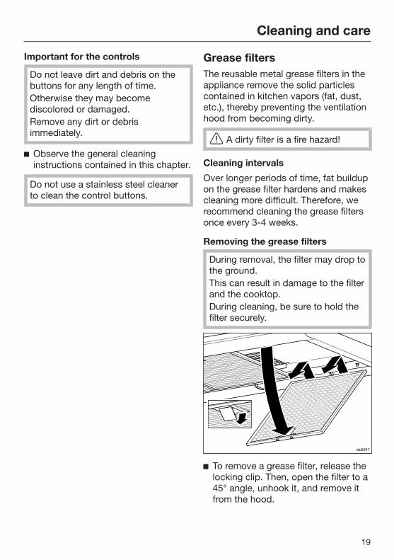
During removal, the filter may drop tothe ground.This can result in damage to the filterand the cooktop.During cleaning, be sure to hold thefilter securely.
To remove a grease filter, release thelocking clip. Then, open the filter to a45° angle, unhook it, and remove itfrom the hood.

Cleaning and care
20
Cleaning the grease filters by hand
Clean the filters with a soft nylonbrush in a mild solution of hot waterand dish soap. Do not use undiluteddish soap.
Unsuitable cleaning agents
Unsuitable cleaners can cause damageto the filter surfaces if used regularly.Do not use any of the following:
– Lime removers
– Abrasive powders or abrasive liquids
– Aggressive all-purpose cleaners anddegreaser sprays
– Oven sprays
Cleaning the grease filters in thedishwasher
Place the filters as upright as possiblein the lower basket. Ensure that thespray arm is not obstructed.
Use a common dishwashingdetergent.
Select a program with a washtemperature between 120°F (50°C)and 150°F (65°C). In a Mieledishwasher use the "Normal"program.
Depending on the detergent used,cleaning the filters in a dishwashermay cause the inside filter surfaces tobecome discolored. However, this willnot affect the functioning of the filtersin any way.
After cleaning
After cleaning, leave the filters on anabsorbent surface to dry.
When removing the filters forcleaning, also clean off anyaccessible oil or fat buildup from thehousing. Doing so will prevent a firehazard.
Reinstall the grease filters. Wheninserting the filters, make sure thatthe locking clip is facing down.
If the filters have been installedincorrectly, you can insert a smallscrewdriver into the slit to disengagethe locking clip.

Cleaning and care
21
OdorFree Charcoal FilterIf the hood is equipped for recirculation,an OdorFree Charcoal Filter must beinstalled in addition to the grease filters.This filter is designed to absorb odor-causing agents and is mounted in thecanopy above the grease filters.
Charcoal filters are available to order viathe Miele Webstore, Miele Service (seeend of this booklet for contact details)or directly from Miele.
Installing/replacing the OdorFreeCharcoal Filter
To install or replace the OdorFreeCharcoal Filter, the grease filters mustfirst be removed as described above.
Remove the charcoal filter from itspackaging.
Slide the OdorFree Charcoal Filterinto the back of the intake frame, thenpush the front of the filter up into theframe.
Reinstall the grease filters.
When to change the OdorFreeCharcoal Filter
Always replace the OdorFreeCharcoal Filter whenever it no longerabsorbs kitchen odors effectively.Replace the filter at least once every6 months.
Disposing of the OdorFree CharcoalFilter
Used OdorFree Charcoal Filters canbe disposed of with normalhousehold waste.

Cleaning and care
22
Changing a light bulbThe bulbs should be replaced with thefollowing:
Bulb type .............................. LED, GU10Power ............................................... 3W
Replacement bulbs are available fromMiele.
Turn off the blower and the lighting.
Only use the specified lamps.Other lamps, for example halogenlamps, may become damaged due tothe high generation of heat.
Disconnect the hood from theelectrical supply before replacing thebulbs (see "IMPORTANT SAFETYINSTRUCTIONS").
Remove the grease filters.
Turn the bolt counterclockwise as faras it will go. The halogen lamp willthen drop down towards you.
Turn the bulb counter-clockwise andpull it out.
Replace the new bulb in reversedorder. Please observe themanufacturer's instructions.
Reinstall the grease filters.
Installation
23
Before installation
Before installing the appliance,read all of the information containedin this chapter and also in the"IMPORTANT SAFETYINSTRUCTIONS" section.
Removing the protective filmThe housing components are coveredby a protective film to prevent themfrom damage during transport.
Please remove this film beforeinstalling the housing components. Itcan be peeled off easily without anyadditional tools.
Installation InstructionsPlease refer to the accompanyinginstallation sheet for instructions onhow to install the appliance.
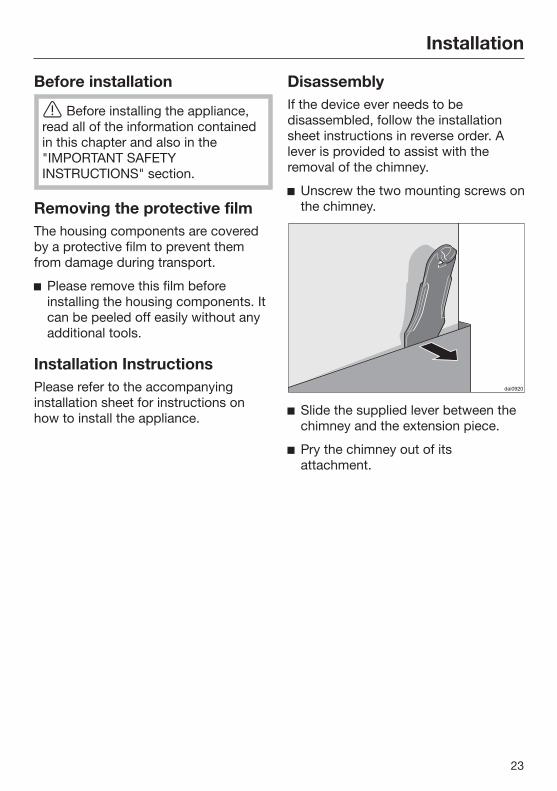
DisassemblyIf the device ever needs to bedisassembled, follow the installationsheet instructions in reverse order. Alever is provided to assist with theremoval of the chimney.
Unscrew the two mounting screws onthe chimney.
Slide the supplied lever between thechimney and the extension piece.
Pry the chimney out of itsattachment.

Installation
24
Installation parts

Installation
25
a 3 protective installation sheetsfor use when installing the chimney
b 1 exhaust connectorfor an exhaust duct 6" (150 mm).
c 1 reducerfor an exhaust duct 5" (125 mm).
d 1 non-return flapfor installation in the outlet ductcollar of the motor unit (not forrecirculation mode). Depending onthe device version, the non-returnflap is already mounted.
e Wall bracketfor securing the hood on the wall.
f Recirculation kit for recirculationmodecontains diverter, aluminum hoseand hose clamps (not contained inscope of delivery, available asoptional accessory – see "TechnicalData").
8 screws, ³/₁₆" x 2 ³/₈" (5 x 60 mm)
8 plugs, ⁵/₁₆" x 2" (8 x 50 mm)for attaching to the wall (not for use inUSA / CDN).
The screws and plugs are designedfor use in solid walls only.Use different fasteners for other wallconstruction types.Make sure that the wall can supportthe load.
2 x M 6 locknutsfor securing the canopy.
2 screws ¹/₈" x ⁵/₁₆" (3.9 x 7.5 mm)for attaching the chimney.
1 leverfor disassembling the chimney.
Montage
Installation
Montaje
M
ontaggio
Montering
Montagem
A
sennus
Installation sheet

Installation
26
Appliance dimensions
The drawing is not to scale.
a Extraction
b Recirculation
c Air vent positioned at top for recirculation

Installation
27
de Mounting area (only d is required for recirculation hoods). Wall and ceilingarea for exhaust duct opening and for wall socket installation. Only the wallsocket installation is required for recirculation hoods.
Vent collar 6" (150 mm), with adapter 5" (125 mm).
Distance between cooktop and ventilation hood (S)
Provided a larger distance is not given by the manufacturer of the cooktop,follow the minimum safety distances between a cooktop and the bottom of thehood.Please also observe the information contained in the "IMPORTANT SAFETYINSTRUCTIONS" section.
Minimum distance S
Cooking appliance Mieleappliance
Non-Mieleappliance
Electric Cooktops 24" (610 mm)
Electric Barbeques and Fryers 26" (660 mm)
Multiburner Gas Cooktops ≤ 43,000 BTU/hr (12.6 kW), no burner > 15,000 BTU/hr (4.5 kW).
26" (660 mm) 30" (760 mm)
Multiburner Gas Cooktops ≤ 73,800 BTU/hr (21.6 kW), no burner > 16,500 BTU/hr (4.8 kW)
30" (760 mm)
Multiburner Gas Cooktops > 73,800 BTU/hr (21.6 kW), or one of the burners > 16,500 BTU/hr (4.8 kW)
Not possible
Single Burner Gas Cooktops ≤ 20,500 BTU/hr (6 kW)
26" (660 mm) 30" (760 mm)
Single Burner Gas Cooktops > 20,500 BTU/hr (6 kW)≤ 27,600 BTU/hr (8.1 kW)
30" (760 mm)
Single Burner Gas Cooktops > 27,600 BTU/hr (8.1 kW)
Not possible
Installation
28
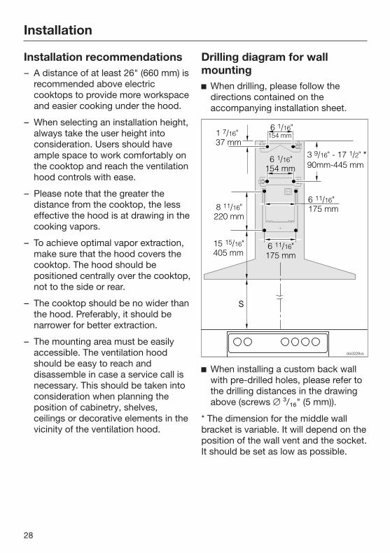
Installation recommendations– A distance of at least 26" (660 mm) is
recommended above electriccooktops to provide more workspaceand easier cooking under the hood.
– When selecting an installation height,always take the user height intoconsideration. Users should haveample space to work comfortably onthe cooktop and reach the ventilationhood controls with ease.
– Please note that the greater thedistance from the cooktop, the lesseffective the hood is at drawing in thecooking vapors.
– To achieve optimal vapor extraction,make sure that the hood covers thecooktop. The hood should bepositioned centrally over the cooktop,not to the side or rear.
– The cooktop should be no wider thanthe hood. Preferably, it should benarrower for better extraction.
– The mounting area must be easilyaccessible. The ventilation hoodshould be easy to reach anddisassemble in case a service call isnecessary. This should be taken intoconsideration when planning theposition of cabinetry, shelves,ceilings or decorative elements in thevicinity of the ventilation hood.
Drilling diagram for wallmounting When drilling, please follow the
directions contained on theaccompanying installation sheet.
When installing a custom back wallwith pre-drilled holes, please refer tothe drilling distances in the drawingabove (screws ³/₁₆" (5 mm)).
* The dimension for the middle wallbracket is variable. It will depend on theposition of the wall vent and the socket.It should be set as low as possible.

Installation
29
Plywood backing
The majority of the weight of theinstalled ventilation system will besupported by the lower retainingplate. It must be firmly attached tothe stud framing behind the drywall.If studs are not available in therequired locations, a plywoodbacking (min. ½" (13 mm) thick)spanning at least two studs must beinstalled.Failure to adequately support theweight as stated may result in theventilation system falling off the wall,causing personal injury and propertydamage.
If plywood backing is not needed,proceed to the included "Installationdiagram".
To install a plywood backing
Determine and mark the location ofthe retaining plate for the canopyas outlined on the "Installationdiagram".
Make a cutting line 3" (76 mm) aboveand 3" (76 mm) below the outline ofthe retaining plate.
Find the studs to the left and rightof the mounting location by tappingthe wall or using a stud finder.
Mark a vertical cutting line along thecenter of each stud.
CAUTION: When cutting or drillinginto the wall or ceiling, do notdamage electrical wiring and otherhidden utilities.
Remove the drywall between thecutting lines and replace it withplywood of a matching thickness(min. ½" (13 mm) thick). Tape thejoints and refinish the wall.
Proceed to the enclosed "Installationdiagram" to complete the installation.

Air venting
30
WARNING: Danger of toxic fumes.Gas cooking appliances releasecarbon monoxide that can beharmful or fatal if inhaled.To reduce the risk of fire and toproperly exhaust air, the exhaustgases extracted by the hood shouldbe vented outside of the buildingonly.Do not vent exhaust air into spaceswithin walls or ceilings or in attics,crawl spaces or garages.To reduce the risk of fire, only usemetal ductwork.Please read and follow the"IMPORTANT SAFETYINSTRUCTIONS" to reduce the riskof personal injury. Follow all localbuilding codes when installing thehood.
Only use smooth pipes or flexibleduct hoses made from non-combustible materials for exhaustductwork.
To achieve the greatest possible airextraction with the lowest noise levels,please note the following:
– The diameter of the exhaust ductshould not be less than 6" (150 mm).
– If flat exhaust ducts are used, thecross section should not be smallerthan that of the exhaust connector.
– The exhaust duct should be as shortand straight as possible.
– If elbows are needed, make sure theyhave a large radius.
– The exhaust duct itself must not bekinked or compressed.
– Make sure that all connections aresecure and airtight.
Remember that any constriction ofthe airflow will reduce extractionperformance and increase operatingnoise.
If the exhaust duct is to be routedthrough an outside wall, werecommend installing a telescopicwall vent or a rooftop vent (availableas an optional accessory).
If the exhaust air is conveyed into anexhaust air chimney, the inletconnector must face the flowdirection.
When installing the exhaust ducthorizontally, a minimum slope of ¹/₈ inch per foot must be maintained toprevent condensate from flowing intothe ventilation hood.
If the exhaust duct is to be routedthrough cool rooms, ceilings, etc., thetemperatures in these different areasmay differ greatly. Therefore watercondensation must be consideredand the exhaust duct will need to beinsulated.

Air venting
31
Condensate trap
In addition to insulating the exhaustduct, we recommend installing acondensate trap to collect andevaporate any condensate which mightaccumulate.Condensate traps are available forexhaust ducts with a diameter of5" (125 mm) or 6" (150 mm).
When installing a condensate trap,make sure that it is positionedvertically and, if possible, directlyabove the hood outlet duct collar.The arrow on the housing indicatesthe direction of airflow.
Reducing Collar(optional accessory)
If you would like to reduce theenvironmental impact of your ventilationsystem by limiting the CFM output theReducing Collar can be installed. Itreduces the air flow to less than400 CFM. Check local building codesfor max. CFM requirements.
Push the Reducing Collar on theexhaust port of the blower.
Push the exhaust hose over it.
Secure both with a hose clamp.

Electrical connection
32
WARNING: TO REDUCE THE RISKOF FIRE, ELECTRIC SHOCK, ORINJURY TO PERSONS, OBSERVETHE FOLLOWING:All electrical work should beperformed by a qualified electricianin strict accordance with nationalregulations (for USA: ANSI-NFPA 70)and local safety regulations.Installation, repairs and other workby unqualified persons could bedangerous.Ensure that power to the appliance isOFF while installation or repair workis performed.Verify that the voltage, load andcircuit rating information found onthe data plate (located behind thebaffle filters), match the householdelectrical supply before installing thehood.Use only with ventilation hood cord-connection kits that have beeninvestigated and found acceptablefor use with this model hood.If there is any question concerningthe electrical connection of thisappliance to your power supply,please consult a licensed electricianor call Miele’s Technical ServiceDepartment.
WARNING: THIS APPLIANCE MUSTBE GROUNDED
Grounding Instructions
WARNING - Improper grounding canresult in a risk of electric shock.
This appliance must be grounded. Inthe event of an electrical short circuit,grounding reduces the risk of electricshock by providing a path of leastresistance. This appliance is equippedwith a cord having a grounding wirewith a grounding plug.
If there is any doubt, have the electricalsystem of the house checked by aqualified electrician.
Do not use an extension cord. If thepower supply cord is too short, have aqualified electrician install an outlet nearthe appliance.
The plug must be plugged into anoutlet that is properly installed andgrounded.
WARNING - Grounding instructions(Canada)The grounding-type attachment plugshall be connected to a grounding-type receptacle installed inaccordance with CSA C22.1-12,Canadian Electrical Code, Part I.
Service and warranty
33
For faults that you cannot resolve onyour own, please contact your Mieledealer or Miele Technical Service.
The telephone number for Miele is listedat the back of these instructions.
When contacting Miele, please state themodel and serial number of yourventilation hood.These can be found on the data plate.
Location of the data plateThe data plate is visible once you haveremoved the grease filters.
WarrantyFor further information, please refer toyour warranty booklet.
MieleCare
This service is available in USA only.
MieleCare, our Extended ServiceContract program, gives you theassurance of knowing that yourappliance investment is covered by5 years of worry free ownership.MieleCare is the only Extended ServiceContract in the industry that guaranteesrepairs by a Miele Authorized ServiceProvider using genuine Miele parts.Only genuine Miele parts installed byfactory trained professionals canguarantee the safety, reliability, andlongevity of your Miele appliance.
Please note that unless expresslyapproved in writing by Miele’s Servicedepartment, Extended ServiceContracts offered by other providers forMiele products will not be recognizedby Miele. Our goal is to preventunauthorized (and untrained) servicepersonnel from working on your Mieleproducts, possibly doing furtherdamage to them, you and/or yourhome.
To learn more about MieleCareExtended Service Contracts, pleasecontact your appliance dealer or visit usonline at:www.mieleusa.com

Technical data
34
Blower motor 350 W
Cooktop lighting 2 x 3 W
Total connected load 356 W
Supply voltage, frequency 120 V AC, 60 Hz
Fuse 15 A
Power cord length 2.5 ft (0.75 m)
Weight
DA 398-7 55.3 lbs (25.1 kg)
DA 399-7 57.2 lbs (26 kg)
Optional accessory for recirculation mode
DUW 20 conversion kit to change from extraction mode to recirculation mode andOdorFree Charcoal Filter DKF 12-900

9 Independence WayPrinceton, NJ 08540Phone:Fax:www.mieleusa.com
U.S.A.Miele, Inc.
National Headquarters
Please have the model and serial numberof your appliance available whencontacting Technical Service.
CanadaImporterMiele Limited
Headquarters and Miele Centre
800-843-7231609-419-4298
Technical Service & SupportPhone:Fax:[email protected]
161 Four Valley DriveVaughan, ON L4K 4V8www.miele.ca
800-999-1360888-586-8056
Customer Care CentrePhone:
800-565-6435905-532-2272
International HeadquartersMiele & Cie. KGCarl-Miele-Straße 2933332 GüterslohGermany

M.-Nr. 10 597 860 / 01en-US
DA 398-7DA 399-7