operating and maintenance manual 190 alpha nrf … - 190 alpha nrf rev. 1.0...operating and...
TRANSCRIPT

Revision 1.0
Date: August 2011
Operating and Maintenance Manual
190 Alpha NRF Docking System
Dynamic Design Pharma, Inc.
23332 Madero Road, Suite J
Mission Viejo, California 92691
Phone 949-643-1120
Fax: 949-639-0440

Operating and Maintenance Manual – 190 Alpha NRF Docking System
Revision 1.0 Dynamic Design Pharma, Inc. Date: August 2011
Page 2
1. GENERAL 3
2. TERMINOLOGY 4
3. SYSTEM COMPONENTS 5
4. SYSTEM ASSEMBLY 7
5. DOCKING INSTRUCTION 18
6. BALL BEARING AND DYNAMIC SEAL REPLACEMENT 23
7. SYSTEM SPECIFICATION 30
8. FUNCTIONAL SPECIFICATION 32
9. DESIGN SPECIFICATION 33
10. RECOMMENDED SPARE PARTS 35
11. ASSEMBLY DRAWINGS 36
12. ATTACHMENTS 36

Operating and Maintenance Manual – 190 Alpha NRF Docking System
Revision 1.0 Dynamic Design Pharma, Inc. Date: August 2011
Page 3
1. GENERAL
1.1. Introduction
This document is the operating and maintenance instruction manual for the 190 Alpha NRF
Docking System manufactured by Dynamic Design Pharma (DDP), Mission Viejo, California.
1.2. General description of the system
The Alpha NRF docking system integrates a standard DPTE Alpha/Beta transfer port system
manufactured by Getinge-La Calhene into a DDP’s proprietary NR flange. The NR flange
permits the docking process to be performed without rotation of the Beta flange relative to the
Alpha flange. For reference, the DPTE system requires a 60 degree rotation of the Beta flange
relative to the Alpha flange to complete the docking process.
The NR flange is based on DDP’s NR technology. The NR technology is adopted in DDP’s
standard NRC Canister, a transfer canister which can be docked without rotation. The NR flange
consists of a dynamic seal and a set of ball bearings that allow proper rotation while maintaining
the integrity of the joint.
The Alpha NRF system is a standard LAC Alpha flange mounted on a specially designed NR
flange. The beta flange is a standard LAC beta flange that is attached to the canister, tank, or
other system to be docked.
The Alpha NRF flange permits the docking of rigidly mounted devices featuring a beta flange to
the Alpha flange by simply rotating the alpha flange during the docking process.
The Alpha NRF Flange is mounted on a silicone rubber diaphragm that permits free float of the
Alpha NRF flange during the docking process.
1.3. Alpha NRF system – Application specific
The application specifically described in this document is one of an Alpha NRF flange used to
dock a tank filled with sterile stoppers to a filling isolator system. The tank features a rigidly
mounted beta flange on its narrow end.

Operating and Maintenance Manual – 190 Alpha NRF Docking System
Revision 1.0 Dynamic Design Pharma, Inc. Date: August 2011
Page 4
2. TERMINOLOGY
2.1. Alpha NRF Flange: Alpha flange that is mounted on a proprietary DDP NR flange.
2.2. Isolation or Barrier Technology: Technology used to maintain containment or sterility of
manufacturing processes.
2.3. RTP: Rapid Transfer Port.
2.4. DPTE: Standard La Calhene RTP port.
2.5. Alpha Flange: The half of the RTP port that is usually attached onto the isolator wall and has the
swing access door.
2.6. Beta Flange: The half of the RTP port which is part of the RTP canister, transfer isolator or other
moveable system.
2.7. LAC: Getinge-La Calhene.

Operating and Maintenance Manual – 190 Alpha NRF Docking System
Revision 1.0 Dynamic Design Pharma, Inc. Date: August 2011
Page 5
3. SYSTEM COMPONENTS
Below is the Alpha NRF system components structure.
3.1. DDA-2027 System Assembly, 190 Alpha NRF Transfer System
3.1.1. DDA-2026 - 190 Alpha NRF Flange Assembly
3.1.1.1. LAC 15511 - 190 DPTE-S Alpha Flange – Getinge-La Calhene
3.1.1.2. DDA-2025 – Assembly, Alpha NRF Flange.
3.1.2. DDA-1803 Beta flange with adapter assembly
3.1.2.1. LAC 20204 – 190 DPTE-S Beta Flange – Getinge-La Calhene
3.1.2.2. DD-2028 – Adapter, 190 beta to IDF flange
Figure 1 – Alpha NRF System Viewed from the sterile side
BETA FLANGE
ALPHA NRF FLANGE
Operating and Maintenance Manual – 190 Alpha NRF Docking System
Revision 1.0 Dynamic Design Pharma, Inc. Date: August 2011
Page 6
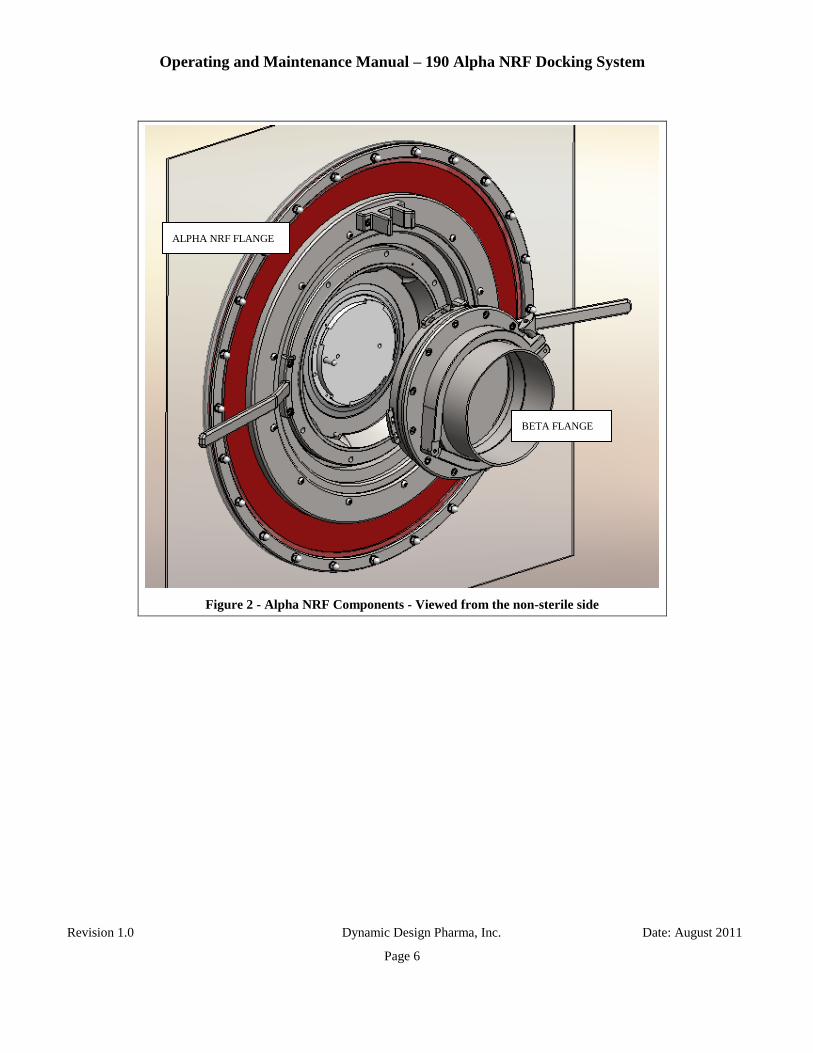
Figure 2 - Alpha NRF Components - Viewed from the non-sterile side
ALPHA NRF FLANGE
BETA FLANGE

Operating and Maintenance Manual – 190 Alpha NRF Docking System
Revision 1.0 Dynamic Design Pharma, Inc. Date: August 2011
Page 7
4. SYSTEM ASSEMBLY
The following instructions describe the assembly of the components with the assumption that they are in
the disassembled state.
4.1. Assembly of the silicone diaphragm to the NRF flange
NOTE
The two handles of the Alpha NR flange must be removed to complete the next
step of the assembly. See re-assembly description below.
4.1.1. Figure 3 shows an exploded view of the Alpha NRF components of the flange that clamp
the silicone diaphragm in place.
4.1.2. Place the male mounting ring into the groove of the main ring.
4.1.3. Place the diaphragm over the main ring boss. It should fit tightly.
4.1.4. While holding the female ring in the groove of the mounting ring, place it over the
silicone diaphragm.
4.1.5. Install all clamping screws and finger tighten
4.1.6. Sequentially tighten the screws down while working around the hole pattern numerous
times. Slowly the silicone diaphragm will deform enough to allow the clamping screws
to bottom out and tighten against the main ring.
NOTE
Do not tighten or loosen the clamping screws unevenly, this might cause the
diaphragm to be improperly clamped in place or the hardware to seize in the
threaded holes.
NOTE
Tighten or loosen the hardware one quarter turn at the time while going around
the hole pattern.

Operating and Maintenance Manual – 190 Alpha NRF Docking System
Revision 1.0 Dynamic Design Pharma, Inc. Date: August 2011
Page 8
Figure 3 - Diaphragm assembly onto Alpha NRF flange
MALE CLAMPING RING
FEMALE CLAMPING RING
SILICONE DIAPHRAGM
MOUNTING RING
MAIN RING
CLAMPING SCREWS

Operating and Maintenance Manual – 190 Alpha NRF Docking System
Revision 1.0 Dynamic Design Pharma, Inc. Date: August 2011
Page 9
Figure 4- Section view of the diaphragm clamping features
FEMALE CLAMPING RING
MALE CLAMPING RING
SILICONE DIAPHRAGM

Operating and Maintenance Manual – 190 Alpha NRF Docking System
Revision 1.0 Dynamic Design Pharma, Inc. Date: August 2011
Page 10
4.2. Assembly of the LAC Alpha flange onto the Alpha NR flange. See Figure 5 and 6.
NOTE
The two handles of the Alpha NRF flange must be removed to complete the next
step of the assembly. See re-assembly description below.
4.2.1. Insert the Alpha flange into the NRF Flange assembly as shown. Assure to place the
sealing gasket provided with the alpha flange between the two assemblies.
Figure 5 – Assembly of the 190 LAC Flange onto the Alpha NRF Flange
4.2.2. Place the alpha flange contrast ring onto the threaded body of the flange.
LAC ALPHA FLANGE
SEALING GASKET
ALPHA NRF FLANGE
CONTRAST RING
LOCKING RING

Operating and Maintenance Manual – 190 Alpha NRF Docking System
Revision 1.0 Dynamic Design Pharma, Inc. Date: August 2011
Page 11
4.2.3. Thread the locking ring onto the threaded portion of the alpha flange body. Rotate until
snug. Do not overtighten.
4.2.4. Tighten all M8 locking set screws to permanently lock the alpha flange ring in place.
NOTE
The relative orientation of the LAC Alpha flange and the Alpha NRF flange
depends on the application. See Figure 6.
4.2.5. The orientation shown in Figure 6 will yield a correct positioning of the LAC Flange
with a horizontal swing of the alpha door when fully docked and a desirable rotation of
the NRF handles.
Figure 6 – LAC Alpha flange to NRF Flange orientation
HANDLE ORIENTATION
LAC FLANGE ORIENTATION

Operating and Maintenance Manual – 190 Alpha NRF Docking System
Revision 1.0 Dynamic Design Pharma, Inc. Date: August 2011
Page 12
4.2.6. Figure 7 shows a cut-away view of the assembly.
Figure 7 – Cross section of the NRF flange with the LAC flange installed
ALPHA NRF FLANGE
LAC ALPHA FLANGE
SILICONE DIAPHRAGM

Operating and Maintenance Manual – 190 Alpha NRF Docking System
Revision 1.0 Dynamic Design Pharma, Inc. Date: August 2011
Page 13
4.3. Assembly of the Alpha NR Flange Assembly onto the isolator wall
NOTE
The two handles of the Alpha NR flange must be removed to complete the next
step of the assembly. See re-assembly description below.
Figure 8 – Assembly of the Alpha NRF Flange onto the isolator wall
NOTE
Do not support the weight of the Alpha NRF flange by the silicone diaphragm
until all the clamping nuts and washers have been completely assembled and
tightened.
4.3.1. Install the sterile side clamping ring on the silicone diaphragm.
CLAMPING RING – STERILE SIDE
ALPHA NRF FLANGE
ISOLATOR WALL
CLAMPING RING – NON-STERILE SIDE
CLAMPING HARDWARE

Operating and Maintenance Manual – 190 Alpha NRF Docking System
Revision 1.0 Dynamic Design Pharma, Inc. Date: August 2011
Page 14
4.3.2. Place the assembly onto the isolator wall.
4.3.3. Install the non-sterile side clamping ring over the threaded studs protruding though the
isolator wall
4.3.4. Install washer and clamping nut. Tighten sequentially around the assembly.
NOTE
The assembly clamps the diaphragm in place. Do not over-tighten the locking
nuts. It is recommended to apply a small amount of low strength thread-lock
compound over the studs of the clamping ring upon assembly.
4.3.5. Figure 9 shows a cut-away view of the NRF Flange mounted onto the isolator wall

Operating and Maintenance Manual – 190 Alpha NRF Docking System
Revision 1.0 Dynamic Design Pharma, Inc. Date: August 2011
Page 15
Figure 9 - Cut away view of assembled alpha NRF flange
LAC ALPHA FLANGE
ALPHA NRF FLANGE
SILICONE DIAPHRAGM
CLAMPING HARDWARE

Operating and Maintenance Manual – 190 Alpha NRF Docking System
Revision 1.0 Dynamic Design Pharma, Inc. Date: August 2011
Page 16
4.3.6. Install the two turning handles onto the Alpha NR flange assembly to complete the
installation. See Figure 10.
Figure 10 - Close up of turning handles installation
HANDLE
LOCKING SCREWS
DOWEL PINS

Operating and Maintenance Manual – 190 Alpha NRF Docking System
Revision 1.0 Dynamic Design Pharma, Inc. Date: August 2011
Page 17
4.4. Beta Flange
4.4.1. Attach the beta flange to the canister or tank using a standard 6 inch IDF sanitary clamp
and gasket. See Figure 11.
Figure 11 - Beta flange attachment to the canister or tank
TANK SIMULATOR
IDF CLAMP
IDF GASKET
BETA FLANGE

Operating and Maintenance Manual – 190 Alpha NRF Docking System
Revision 1.0 Dynamic Design Pharma, Inc. Date: August 2011
Page 18
5. DOCKING INSTRUCTION
NOTE
For instruction purposes, the following images show the beta flange attached to a
simulator of the tank.
5.1. Bring the beta flange into proximity to the alpha flange
5.2. Rotate the Alpha NRF flange to bring the receptacles of the alpha flange into alignment with the
lugs of the beta flange. See Figure 12
Figure 12 - Beta lug alignment with alpha flange
5.3. Bring the beta flange into close proximity to the alpha flange while making sure to keep the two
flanges parallel and centered to each other. See Figures 13 and 14.
ALPHA FLANGE RECEPTACLE
BETA FLANGE LUG

Operating and Maintenance Manual – 190 Alpha NRF Docking System
Revision 1.0 Dynamic Design Pharma, Inc. Date: August 2011
Page 19
Figure 13 - Approximate position of handle upon docking
Figure 14 - Alpha flange orientation upon docking

Operating and Maintenance Manual – 190 Alpha NRF Docking System
Revision 1.0 Dynamic Design Pharma, Inc. Date: August 2011
Page 20
5.4. Use the handles of the Alpha NRF flange to pull the flange into contact with the beta flange.
Once in contact, turn the Alpha NRF flange counterclockwise (CCW) to dock the two assemblies
together.
5.5. See Figures 15 and 16
5.6. Make sure to turn the Alpha NRF flange the full 60 degrees required for a full docking.
Figure 15 - Approximate handle orientation after docking

Operating and Maintenance Manual – 190 Alpha NRF Docking System
Revision 1.0 Dynamic Design Pharma, Inc. Date: August 2011
Page 21
Figure 16 - Approximate alpha flange orientation after docking
5.7. Once the alpha and the beta flanges are docked, open the Alpha/Beta door by actuating the door
locking mechanism.
5.8. The door is now free to be opened. See Figure 17.
ALPHA DOOR LOCK

Operating and Maintenance Manual – 190 Alpha NRF Docking System
Revision 1.0 Dynamic Design Pharma, Inc. Date: August 2011
Page 22
Figure 17 - Alpha/Beta door open into isolator
`

Operating and Maintenance Manual – 190 Alpha NRF Docking System
Revision 1.0 Dynamic Design Pharma, Inc. Date: August 2011
Page 23
6. BALL BEARING AND DYNAMIC SEAL REPLACEMENT
Replacement of the ball bearings and/or dynamic seal requires the disassembly of the Alpha NRF flange.
To accomplish this, the flange must be removed from the isolator system.
6.1. Remove the silicone diaphragm from the Alpha NRF Flange. See appropriate section.
6.2. Remove the LAC Alpha flange from the Alpha NRF flange. See appropriate section.
6.3. Proceed with Alpha NRF flange disassembly.
NOTE
The following maintenance activity requires handling numerous small precision
parts, the ball bearings. It is recommended to pursue this activity on a flat, clean
surface that has raised edges to contain the ball bearings.
6.4. Alpha NRF Flange disassembly
6.4.1. Remove and set aside the two turning handles. See Figure 18.
Figure 18 - Handle removal
MOUNTING SCREWS
DOWEL PINS
HANDLE

Operating and Maintenance Manual – 190 Alpha NRF Docking System
Revision 1.0 Dynamic Design Pharma, Inc. Date: August 2011
Page 24
6.4.2. While laying the assembly flat on a clean surface, remove the outer ring by unscrewing
the 12 M6 socket head caps screws that clamp the assembly together. This exposes the
ball bearings top row. See Figure 19
Figure 19 - Outer ring removal
NOTE
Each ball bearing row consists of alternating Teflon (PTFE) and stainless steel
balls. Make sure to follow the same component order during re-installation of the
components.
OUTER RING
BALL BEARING TOP ROW

Operating and Maintenance Manual – 190 Alpha NRF Docking System
Revision 1.0 Dynamic Design Pharma, Inc. Date: August 2011
Page 25
6.4.3. Remove all ball bearings from the upper groove. See Figure 20.
Figure 20 - Ball Bearings removal - Top row
6.4.4. Grab the assembly at 9 o’clock and 3 o’clock and, while holding it together, flip it over
back onto the clean flat work surface. See Figure 21
Figure 21 – Flange assembly flipped over

Operating and Maintenance Manual – 190 Alpha NRF Docking System
Revision 1.0 Dynamic Design Pharma, Inc. Date: August 2011
Page 26
6.4.5. Lift the outer flange to expose the ball bearing row and the dynamic seal. See Figure 22.
NOTE
Each ball bearing row consists of alternating Teflon (PTFE) and stainless steel
balls. Make sure to follow the same component order during re-installation of the
components.
Figure 22 - Outer flange removal to expose dynamic seal and ball bearings
OUTER FLANGE
BALL BEARING ROW
DYNAMIC SEAL

Operating and Maintenance Manual – 190 Alpha NRF Docking System
Revision 1.0 Dynamic Design Pharma, Inc. Date: August 2011
Page 27
6.4.6. Remove the Teflon dynamic seal and the compression seal from the upward facing
groove. See Figure 23.
Figure 23 - Dynamic seal removal
6.4.7. Inspect and replace, if necessary, the dynamic seal and compression seal.
6.4.8. This completes the disassembly of the Alpha NR flange.
COMPRESSION SEAL
DYNAMIC SEAL

Operating and Maintenance Manual – 190 Alpha NRF Docking System
Revision 1.0 Dynamic Design Pharma, Inc. Date: August 2011
Page 28
6.5. Flange re-assembly
6.5.1. Clean the ball bearing races and the dynamic seal groove using Isopropyl Alcohol.
6.5.2. Perform a final inspection of the ball bearing races and dynamic seal groove to make
sure that they are free of dirt or lint.
NOTE
The ball bearing row consists of alternating Teflon and stainless steel ball. Make
sure to create the same alternating pattern upon re-assembly of the flange
NOTE
The silicone compression seal must be well placed in the groove upon
reassembly. Make sure that it is well centered and not twisted. The silicone seal
is easier to manipulate when wet. Place a small amount of Isopropyl Alcohol in
the groove to facilitate this process.
6.5.3. Reverse the steps outline above to reassemble the flange.
6.5.4. Refer to figure 24 for a cross sectional view of the Alpha NR flange. This view will help
the mechanic understand the assembly of the Alpha NR flange.
Figure 24 - Cross section view of the Alpha NRF flange

Operating and Maintenance Manual – 190 Alpha NRF Docking System
Revision 1.0 Dynamic Design Pharma, Inc. Date: August 2011
Page 29
6.5.5. Once reassembled, test the NRF flange for proper operation.
6.5.5.1. Use the turning handles to turn the inner ring relative to the outer flange. The
rotation should be smooth and with slight resistance.
6.5.5.2. The smoothness is an indication that the ball bearings have been properly
installed.
6.5.5.3. The resistance to turning is an indication that the dynamic seal was properly
installed and is working properly.
6.5.5.4. It is recommended to run an ammonia leak test after such major overall of the
Alpha NRF flange.

Operating and Maintenance Manual – 190 Alpha NRF Docking System
Revision 1.0 Dynamic Design Pharma, Inc. Date: August 2011
Page 30
7. SYSTEM SPECIFICATION
7.1. Human factor and safety
7.1.1. The Alpha NRF flange fastens securely but in a flexible manner to the isolator bulkhead.
7.1.2. The LAC 190 Alpha Port fastens securely in the Alpha NR flange.
7.1.3. The Alpha NR handles permit turning the flange with a maximum force of 4.5 Kg (10
lbs.)
7.1.4. Docking the beta flange to the Alpha NRF requires a turning force that is typical of
alpha/beta port docking operations.
7.2. Physical configuration
7.2.1. Beta flange
7.2.1.1. Standard Beta flange including door and seal
7.2.1.2. Adapter Beta flange to Canister: 6 inch IDF flange interface
7.2.2. Alpha flange
7.2.2.1. Standard Alpha flange including polyethylene door and seal
7.2.3. Alpha NRF flange
7.2.3.1. Dynamic seal system that permits turning the alpha flange relative to the
isolator wall
7.2.3.2. Docking handles 180 degrees apart allow the operator to turn the Alpha NR
flange during docking operations.
7.2.3.3. Bearing system consisting of multiple ball bearings housed inside machined
grooves that permit rotation of the beta flange relative to the canister body.
7.3. Mounting
7.3.1. The Alpha NRF flange can be mounted and operated at any mounting orientation
(Vertically, horizontally and at any angle in between).
7.3.2. Attachment to the isolator wall
7.3.2.1. Flexible attachment using a silicone diaphragm
7.3.2.2. Stainless steel frame to clamp the diaphragm to the isolator wall.
7.4. Physical specification
7.4.1. Nominal port size: 190mm.
7.4.2. Weight
7.4.2.1. Alpha NR flange: 27 Kg.
7.4.2.2. Alpha Flange and Door: 17.5 Kg.
7.4.2.3. Beta flange and adapter: 10 Kg.
7.4.3. Outside diameter of Alpha NRF flange: 464mm.

Operating and Maintenance Manual – 190 Alpha NRF Docking System
Revision 1.0 Dynamic Design Pharma, Inc. Date: August 2011
Page 31
7.4.4. Diameter of opening in isolator wall: 550mm.
7.4.5. Swing radius of turning handles: 800mm.
7.5. Cleaning and sterilization capability
7.5.1. The Alpha NRF flange is designed to withstand and facilitate standard cleaning
procedures using cleaning agents that are commonly used in aseptic applications.
7.5.2. Materials of construction are compatible with the VHP decontamination process.
7.6. Leak Tightness
7.6.1. The Alpha NRF flange is capable of passing an ammonia leak test from either side when
pressurized to 250 PA maximum.
7.6.2. The fully assembled system (Alpha, Beta and Alpha NRF Flange) is capable of passing
ammonia leak test when pressurized to 250 PA

Operating and Maintenance Manual – 190 Alpha NRF Docking System
Revision 1.0 Dynamic Design Pharma, Inc. Date: August 2011
Page 32
8. FUNCTIONAL SPECIFICATION
8.1. Docking functionality: Beta flange to Alpha flange
8.1.1. The Alpha NRF flange is such that the standard Alpha flange mounting within the Alpha
NRF flange permits unobstructed docking of the Beta flange.
8.1.2. The Alpha NRF flange is such that the beta flange can be docked without any rotation of
the beta flange.
8.2. Alpha Flange rotation
8.2.1. The Alpha NRF rotation is smooth through its 60 degrees of travel.
8.2.2. Rotation of the Alpha NRF flange is accomplished by using two handles provided.
8.2.3. Torque required to lock the beta flange onto the Alpha NRF assembly is 4.5Kg
maximum.
8.3. Beta door removal.
8.3.1. Removal of the beta door from the beta flange can be easily accomplished with the aid of
the beta door removal tool P/N DD-1825.

Operating and Maintenance Manual – 190 Alpha NRF Docking System
Revision 1.0 Dynamic Design Pharma, Inc. Date: August 2011
Page 33
9. DESIGN SPECIFICATION
9.1. Alpha Flange
9.1.1. The Alpha flange is a standard Getinge-La Calhene 190 size Alpha Flange.
9.2. Beta flange
9.2.1. The Beta flange is a standard Getinge-La Calhene 190 size Beta Flange.
9.3. Alpha NRF Flange
9.3.1. The Alpha NRF flange is a proprietary Dynamic Design Pharma assembly.
9.3.2. The Alpha NRF flange features a bearing system which allows smooth and accurate
rotation of the Alpha flange relative to the beta flange.
9.3.3. The Alpha NRF flange features a dynamic seal which creates a seal between opposite
sides of the flange while permitting free rotation of flange components relative to each
other.
9.3.4. The Alpha NRF flange features two handles 180 degrees apart that allow the operator to
turn and lock the Alpha NR flange relative to the beta flange.
9.4. Dynamic seal
9.4.1. The dynamic seal creates an airtight interface between opposite sides of the Alpha NRF
flange.
9.4.2. The dynamic seal is a face seal. This seal requires a preload force applied by a molded
silicone compression seal.
9.4.3. The dynamic seal material is PTFE. Because of the low friction property of the PTFE
material, the dynamic seal requires low force to actuate.
9.5. Ball Bearing system
9.5.1. The ball bearing system consists of a multitude of ball bearings which are housed in
grooves machined in the Alpha NR flange.
9.5.2. The bearing system consists of two rows of ball bearings that provide radial and axial
positioning.
9.5.3. Ball bearing material is stainless steel and PTFE.
9.5.4. The dynamic seal design is such that ball bearing preload is not necessary.
9.6. Mounting to the isolator wall
9.6.1. The Alpha NRF is mounted to the isolator wall with a 6.35mm thick silicone rubber
diaphragm.
9.6.2. The diaphragm attaches to the Alpha NRF flange by two stainless steel compression
rings under load by a number of radially located M6 screws.

Operating and Maintenance Manual – 190 Alpha NRF Docking System
Revision 1.0 Dynamic Design Pharma, Inc. Date: August 2011
Page 34
9.6.3. The diaphragm attaches to the isolator wall by means of two stainless steel clamping
rings compressed together by a series of radially located clamping studs and acorn nuts.
9.7. Materials of construction and surface treatment
9.7.1. Alpha NRF flange: 316L Stainless Steel.
9.7.2. Dynamic Seal: PTFE and Silicone.
9.7.3. Alpha Flange: 316L Stainless Steel and silicone.
9.7.4. Beta Flange: 316L Stainless Steel and silicone.
9.7.5. Ball bearings: 316L Stainless Steel and PTFE.
9.7.6. Hardware: 18-8 stainless steel, metric socket head and button head cap screws.

Operating and Maintenance Manual – 190 Alpha NRF Docking System
Revision 1.0 Dynamic Design Pharma, Inc. Date: August 2011
Page 35
10. RECOMMENDED SPARE PARTS
Following are recommended spare parts for the system
Item Qty/unit Part number Description Manufacturer
1 1 LAC 20161 190mm Beta Gasket Seal Getinge-La Calhene
3 1 LAC 373 190mm Alpha Gasket Seal Getinge-La Calhene
4 1 DD-1805 Dynamic Seal DDP
5 1 DD-2199 Dynamic Seal, Compression DDP
6 1 DD-2160 Diaphragm DDP
7 200 96415K75 Ball Bearing – Stainless Steel McMaster
8 200 9660K37 Ball Bearing – PTFE McMaster

Operating and Maintenance Manual – 190 Alpha NRF Docking System
Revision 1.0 Dynamic Design Pharma, Inc. Date: August 2011
Page 36
11. ASSEMBLY DRAWINGS
The following assembly drawings are included in this document.
11.1. DD-2084 System Outline, 190 Alpha NRF
11.2. DD-2189 Outline, beta flange with IDF Adapter
11.3. DDA-2027 System Assembly, 190 Alpha NRF
11.4. DDA-2026 Assembly, Alpha Flange to NRF Flange.
11.5. DDA-2025 Assembly, 190 Alpha NRF Flange.
11.6. DDA-2028 Assembly, Beta Flange to Canister.
12. ATTACHMENTS
12.1. Certifications
12.1.1. Materials
12.1.2. Surface Treatment
12.2. Factory Acceptance Test (executed)
12.3. Leak test reports