operating and maintenance manual alfa split body …doc. nr. mm6x rev.9 en operating and maintenance...
TRANSCRIPT

Doc. Nr. MM6X Rev.9 EN OPERATING AND MAINTENANCE MANUAL
SPLIT BODY FLOATING BALL VALVES Sheet 1 of 12
OPERATING AND MAINTENANCE MANUAL ALFA SPLIT BODY FLOATING BALL VALVES
Models ALFA 60 / 64 / 68 / 606 / 609 / 615 / 625 / 50 / 54 / 58 / 506 (valid for S.B. valves both for D.B.B. valves)
INDEX PAGE 0. Technical Data 2 1. Transportation, handling and storage 4 2. Installation instructions 4 3. Maintenance 5 4. Testing 5 5. How to order spare parts 7 6. Warnings and use limitations 7 7. “X” – Special Conditions for Safe Use 8 8. Trouble shooting 9 9. Maintenance card type ALFA 5x/6x SB ball valves 10 10. Maintenance card type ALFA 5x/6x DBB ball valves 12
English Version – Original Operating and Maintenance Manual
Doc. Nr. MM6X Rev.9 EN OPERATING AND MAINTENANCE MANUAL
SPLIT BODY FLOATING BALL VALVES Sheet 2 of 12
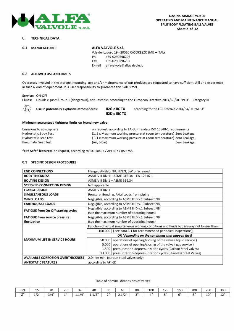
0. TECHNICAL DATA 0.1 MANUFACTURER ALFA VALVOLE S.r.l. V.le del Lavoro 19 - 20010 CASOREZZO (MI) – ITALY Ph. +39-0290296206 Fax. +39-0290296292 E-mail [email protected] 0.2 ALLOWED USE AND LIMITS Operators involved in the storage, mounting, use and/or maintenance of our products are requested to have sufficient skill and experience in such a kind of equipment. It is user responsibility to guarantee this skill is met. Service: ON-OFF Fluids: Liquids e gases Group 1 (dangerous), not unstable, according to the European Directive 2014/68/UE “PED” – Category III
Use in potentially explosive atmospheres: II2G c IIC TX according to the EC Directive 2014/34/UE “ATEX”
II2D c IIIC TX Minimum guaranteed tightness limits on brand new valve:
Emissions to atmosphere on request, according to TA-LUFT and/or ISO 15848-1 requirements Hydrostatic Body Test (1, 5 x Maximum working pressure at room temperature) Zero Leakage Hydrostatic Seat Test (1, 1 x Maximum working pressure at room temperature) Zero Leakage Pneumatic Seat Test (Air, 6 bar) Zero Leakage “Fire Safe” features: on request, according to ISO 10497 / API 607 / BS 6755.
0.3 SPECIFIC DESIGN PROCEDURES
END CONNECTIONS Flanged ANSI/DIN/UNI/EN, BW or Screwed
BODY THICKNESS ASME VIII Div.1 – ASME B16.34 – EN 12516-1
BOLTING DESIGN ASME VIII Div.1 – ASME B16.34
SCREWED CONNECTION DESIGN Not applicable
FLANGE DESIGN ASME VIII Div.1
SIMULTANEOUS LOADS Pressure, Bending, Axial Loads from piping
WIND LOADS Negligible, according to ASME III Div.1 Subsect.NB
EARTHQUAKE LOADS Negligible, according to ASME III Div.1 Subsect.NB
FATIGUE from On-Off starting cycles Negligible, according to ASME III Div.1 Subsect.NB (see the maximum number of operating hours)
FATIGUE from service pressure fluctuation
Negligible, according to ASME III Div.1 Subsect.NB (see the maximum number of operating hours)
MAXIMUM LIFE IN SERVICE HOURS
Function of actual simultaneous working conditions and fluids but anyway not longer than :
100.000 ( see para 3.1 for recommended periodical inspections);
OR (depending on the conditions that happen first)
50.000 5.000 1.500
13.000
operations of opening/closing of the valve ( liquid service ) operations of opening/closing of the valve ( gas service ) pressurization-depressurization cycles (Carbon Steel valves) pressurization-depressurization cycles (Stainless Steel Valves)
AVAILABLE CORROSION OVERTHICKNESS 2.0 mm min. (carbon steel valves only)
ANTISTATIC FEATURES according to API 6D
Table of nominal dimensions of valves
DN 15 20 25 32 40 50 65 80 100 125 150 200 250 300
Ø” 1/2” 3/4” 1” 1.1/4” 1.1/2” 2” 2.1/2” 3” 4” 5” 6” 8” 10” 12”

Doc. Nr. MM6X Rev.9 EN OPERATING AND MAINTENANCE MANUAL
SPLIT BODY FLOATING BALL VALVES Sheet 3 of 12
Tab.1– Main design features of models A6x and A5x
Model
ALFA 64 (***) ALFA 68 (***) (DN≤80 PN40) (DN>80 PN16)
ALFA 60(***) ALFA 606 (***) ALFA 609 (***) ALFA 615 (***) ALFA 625 (***)
ALFA 54 ALFA 58
(DN≤100 PN40) (DN>100 PN16)
ALFA 50 ALFA 506
Class PN10-16-25-40
ANSI 150 PN25-40 ANSI 300
PN63-100 ANSI 600
PN160 ANSI 900
PN250 ANSI 1500
PN420 ANSI 2500
PN10-16-25-40 ANSI 150
PN25-40 ANSI 300
PN63-100 ANSI 600
Nominal Diameter DN 15÷250 DN 15÷150 DN 15÷150 DN 15÷40 DN 15÷40 DN 15÷40 DN 50÷300 DN 50÷300 DN 50÷150
Maximum working pressure at room
temperature (bar)
10 PN10 PN25 PN25 64 51
PN63 DN 150 160 PN160 250 PN250 420 PN420
10 PN10 25 PN25 64 PN63
16 PN16 PN40 PN40
100 64 51
PN100 DN ≥ 100 DN 150
16 PN16 40 PN40 100 PN100
25 PN25
152 A.900 255 A.1500 425 A.2500
25 20
PN25 DN ≥ 200
40 PN40 51 A.300
102 64 51
A.600 DN ≥ 100 DN 150
40 40 25 20
PN40 DN ≤ 80
DN ≥ 150 DN ≥ 200
51 A.300 102 A.600
20 A.150 20 A.150
Maximum working pressure at maximum
temperature (bar)
8 8
15
PN25-40
A.300
63 PN63
135
140
A.900
PN160
225
220
A.1500
PN250
375
352
A.2500
PN420 8
8
15
PN25-40
A.300
63 PN63
80 63
PN100 DN>80
80 63
PN100 DN>80
80 63
A.600 DN>80
80 63
A.600 DN>80
Pressure values between room temperature and maximum temperature vary depending of characteristics of used seats/seals materials. Please contact ALFA VALVOLE Technical Dept. for more information.
Maximum working temperature
240ºC* 160ºC* 120ºC*
DN≤100 DN≤150 DN≥200
240ºC* 160ºC* 120ºC*
DN≤100 DN≤150 DN≥200
240ºC* 180ºC*
DN≤50 DN≤100
150ºC* 150ºC* 150ºC* 240ºC* 160ºC* 120ºC*
DN≤100 DN≤150 DN≥200
240ºC* 160ºC* 120ºC*
DN≤100 DN≤150 DN≥200
240ºC* 180ºC*
DN≤65 DN≤150
Minimum working and room temperature
-29ºC* for carbon steel A105 / A216 WCB valve bodies with impact test verification when TR** ≤ 21°C
-40ºC* for carbon steel A350 LF2 / A352 LCB valve bodies
-46ºC* for carbon steel A350 LF2 / A352 LCB valve bodies With impact test verification (valve without O-Ring and with Chevron Ring)
-40ºC* for stainless steel valve bodies without impact test verification
-70ºC* for stainless steel valve bodies Without impact test verification (valve without O-Ring and with Chevron Ring)
Maximum simultaneous working
conditions Please contact ALFA VALVOLE Technical Dept.
* Other restrictions imposed from the material of the seat ring, the gasket material and the nominal diameter of the valve will be indicated on the nameplate attached to the valve body. ** TR = design temperature, for impact test verification, according to the standard EN13445-2 “Unfired Pressure Vessels – Materials”, para 4.1.6 e Annex B. The body thickness is assigned so that the design temperature, for impact test verification according to the standard EN13445-2, are above 21 ° C *** Includes D.B.B. models A64 DBB, A60 DBB, A606 DBB, A609 DBB, A615 DBB, A625 DBB, A54 DBB, A50 DBB, A506 DBB

Doc. Nr. MM6X Rev.9 EN OPERATING AND MAINTENANCE MANUAL
SPLIT BODY FLOATING BALL VALVES Sheet 4 of 12
1. TRANSPORT, HANDLING AND STORAGE 1.1 TRANSPORT AND HANDLING
Valves must be transported and handled maintaining the ball in the open position. DO NOT remove the protection caps from the ends until the valve is to be mounted in line.
Avoid impacts against obstacles that may damage the stem or the auxiliary connections (drains, sealant injectors, vents).
1.2 STORAGE
Valves with carbon steel or stainless steel bodies must both be stored with ball in the OPEN position and in a location dry and free from fumes, gas or corrosive vapours. For long storage periods it is advisable to cover the external surface with a layer of protective wax (Tectyl) or close the valves in polythene bags.
2. INSTALLATION INSTRUCTIONS The installation procedure for ball valves is critical to ensuring both long life and satisfying performance. Valves stored on site awaiting installation should be kept in their original packing, in dry conditions, where damage cannot occur. Before carrying out the installation, it is important to follow the basic procedures described below:
2.1 General Carefully unpack the valve and check valve nameplate for identification of materials.
Remove all packing materials.
All valves are bi-directional and supplied ready to use. Valves can be placed with stem oriented to any direction.
Check the valve for any flow direction indication marks. Appropriate care must be taken, to install the valve for proper flow orientation.
Inspect the valve interior through the end ports to determine it is clean and free from foreign matter according to ASME G93-03E1.
Ensure that all auxiliary connections, if any, (lubricators, drains, vents) are free of damage and properly tightened.
Cycle the valve and inspect any functionally significant features.
Read all the literature and note any special warning tags or plates attached to the valve.
Before installation check to insure the ball is in the fully open position in order to prevent possible damage to the ball and seats. The valve performance depends on its original conditions. At any stage do not leave the valve in the partially open position.
2.2 Threaded End Valves Valves with threaded ends should be treated as a single unit and should not be dismantled when installing to pipeline.
Before installing the valves, make sure that the threads on the mating pipe are free from excessive grit, dirt or burrs.
When tightening the valve, apply a pipe wrench or spanner to the end connector closest to the pipe being worked, using standard piping practices.
Use appropriate joining sealants material in correct quantities.
2.3 Weld End Valves in-line Welding of valves shall be performed by a qualified person according to the ASME Boiler Construction Code Section IX. For
valves to be welded within the E.U., refer to the requirements of ESR 3.1.2 of the Pressure Equipment Directive 2014/34/UE.
Valves that will be welded directly to the line must be in the fully open position to protect the ball and seats from excessive temperatures during the welding procedures.
Protect or remove actuators from weld splatter or arc strikes. Valves in the “Fail Close” position should be cycled to the open position.
Allow free flow of water through the drain bottom valve and overflow through the vent valve to prevent overheating all through the welding process. DO NOT heat the center section over 150°C
Align valve to pipe line, ensuring proper fit to minimize pipe load. Tack weld only.
Complete welding in small segments. Allow enough time for cooling between each segment.
Do not rotate the valve before flushing the line.

Doc. Nr. MM6X Rev.9 EN OPERATING AND MAINTENANCE MANUAL
SPLIT BODY FLOATING BALL VALVES Sheet 5 of 12
2.4 Flanged End Valves Valves with flanged ends should be treated as a single unit and should not be dismantled when installing to pipeline.
Before installing the valves, make sure that the flanges on the mating pipe are free from excessive grit, dirt or burrs, and that there is no mechanical damage to the flanges on the pipe.
When inserting the flange bolts, make sure the bolts are correct size to hold pressure and axial forces.
ATTENTION: When the valve installation has been completed, a full functional test needs to be performed. The test must verify the valve’s ability to open and close completely, whether it is activated manually or with the help of gearboxes or actuators and, if applicable, the correct operation of position indicators and/or other auxiliary devices. The acceptance criteria will be as follows: - It must be possible to move the ball between open and closed positions. - Any position indicator and/or auxiliary devices must indicate the correct position of the ball For more detailed information about the test performing, please contact ALFA VALVOLE Production Dept. for further information
ALFA VALVOLE Ball Valves provide tight shut off when used under normal conditions and in accordance with ALFA VALVOLE published pressure/temperature chart. Valve operation works by operating the valve handle 90°turn counter-clockwise to open, and 90° turn clockwise to close. All standard valves are bidirectional and as such, can be installed for flow in either direction. Valves which are unidirectional will have a flow direction arrow welded to the body and separate assembly instructions. A lubricant is applied through grease fittings on both ends and gland, to assist valve break in. The lubricant, if unacceptable, may be removed by a solvent wash. If a shut-off valve is installed for end of line service, it must be ensured that it is closed with a blind end connection and the valve is secured against being opened unintentionally. WARNING: Never look into the valve bore while the valve is in a flow-line. Pressure and fluids could escape from the valve causing injury. To prevent leakage, malfunctions resulting from internal wear or seal degradation, the user must establish a preventive maintenance and inspection program. This program must include: a. Inspection of parts to detect loss of wall thickness which may result in decreased pressure capacity b. Routine replacement of seals and inspection for proper operation.
3. MAINTENANCE 3.1 A general control of the valve is advisable every 2 years of functioning or every 5.000 opening and closing cycles. 3.1.1 Remove electric and pneumatic or hydraulic actuators power supplies before removing the valve from piping or before any
maintenance or cleaning adjustment.
ATTENTION: check absence of electric and pneumatic or hydraulic actuators power supplies before disconnecting. The execution of eventual intervention must follow the procedure illustrated on the attached card. In occurrence of dirty fluids interception, more frequent periodic checks are recommended, please contact ALFA VALVOLE Technical Dept for further information. ATTENTION: it’s user's responsibility to maintain the safety features of the product and of their components in case of maintenance / repair on their own.
4. TESTING
4.1 S.B. VALVES (SINGLE BALL) 4.1.a Before carrying out of any test, to verify there are no problems in the movement of the ball, make at least one complete stroke of
opening and closing.
4.1.b Valve must be tested using the following procedure:
a) Place the ball in a semi-open position b) Pressurise the valve body, by water, with a pressure 1,5 times the maximum operating pressure at room temperature

Doc. Nr. MM6X Rev.9 EN OPERATING AND MAINTENANCE MANUAL
SPLIT BODY FLOATING BALL VALVES Sheet 6 of 12
(See table at para 0.2) c) Verify that there are no leaks from the body seals d) Release the pressure e) Close the valve f) Pressurise the first seat with water at a pressure 1,1 times the maximum operating pressure at room temperature
(See table at para 0.2) g) Verify that there are no leaks from the end opposite to that pressurised h) Release the pressure i) Pressurise the second seat (if present) with water at a pressure 1,1 times the maximum operating pressure at room temperature
(see table at para 0.2) j) Verify that there are no leaks from the end opposite to that pressurised k) Release the pressure and drain the valve completely of any water l) Repeat the tests described in points f) and i) using air at 6 bar and verifying that there are no leaks from the end opposite to that
pressurised
4.2 DBB VALVES (DOUBLE BALL)
4.2.a Before carrying out of any test, to verify there are no problems in the movement of the ball, make at least one complete stroke of
opening and closing with each of the two levers.
4.2.b Valve must be tested using the following procedure:
a) Place the two balls in a semi-open position b) Pressurise the valve body, by water, with a pressure 1,5 times the maximum operating pressure at room temperature
(See table at para 0.2) c) Verify that there are no leaks from the body seals d) Release the pressure e) Close the upstream ball, open the drain plug between the 2 balls, maintain the downstream ball in a semi-open position; f) Pressurise the first upstream seat with water at a pressure 1,1 times the maximum operating pressure at room temperature ( see
table at para 0.2 )v g) Verify that there are no leaks from the drain hole between the 2 balls; h) Release the pressure i) Open the upstream ball, close the drain hole and close the downstream ball; j) Pressurise the first upstream seat with water at a pressure 1,1 times the maximum operating pressure at room temperature ( see
table at para 0.2 ) k) Verify that there are no leaks from the end opposite to that pressurised l) Release the pressure m) Close the downstream ball, open the drain hole between the 2 balls, maintain the upstream ball in a semi-open position; n) Pressurise the first downstream seat with water at a pressure 1,1 times the maximum operating pressure at room temperature (
see table at para 0.2 ); o) Verify that there are no leaks from the drain hole between the 2 balls; p) Release the pressure; q) Open the downstream ball, close the drain hole and close the upstream ball; r) Pressurise the first downstream seat with water at a pressure 1,1 times the maximum operating pressure at room temperature (
see table at para 0.2 ); s) Verify that there are no leaks from the end opposite to that pressurised; t) Release the pressure and drain the valve completely of any water through the drain hole between the 2 balls; u) Repeat the tests described in points f) and i) using air at 6 bar and verifying that there are no leaks from the end opposite to that
pressurized.
WARNING: during the test, valve must be firmly blocked on the test rig to avoid any possible danger to personnel caused by the pressure. ALFA VALVOLE declines all responsibility regarding damage to things or people following to tests carried out in accordance with the above procedure.
ATTENTION : while considering the above information sufficient for proper execution of the maintenance of the valve, ALFA
VALVOLE not give any warranty on the outcome of the intervention, not extended warranty, unless the action is performed by ALFA VALVOLE personnel at its workshops.

Doc. Nr. MM6X Rev.9 EN OPERATING AND MAINTENANCE MANUAL
SPLIT BODY FLOATING BALL VALVES Sheet 7 of 12
5. HOW TO ORDER SPARE PARTS 5.1 User must specifies, when ordering spare parts:
Valve model Nominal diameter
Pressure class Identification number or name of the part to be substituted (ref. attached card)
Material of the spare part (or of the original part) Original order number or serial number of the valve
6. WARNINGS AND USE LIMITATIONS 6.1 Here described valves are intended for use with clean or slightly abrasive fluids (without solid particles).
ATTENTION: their use with abrasive fluids can cause the rapid decay of the sealing characteristics of the valve during operation; Any presence of solids or the use with hardening fluids which harden can cause a quick reduction of the tightness and of the operability.
6.2 User must provide adequate methods to eliminate risks associated with the temperature of the external surface of the valve during operations.
ATTENTION: User must evaluate the valve body surface temperature when the outside ambient has potentially explosive conditions. It is not possible to identify the body surface temperature in accordance to the Directive 2014/34/UE “ATEX” because it is a function of handled fluid temperature (surface temperature of valve body tends to reach the temperature of intercepted fluid). For that reason the valve marking will be TX, giving all information as indicated at paragraph 7. The end user shall make an assessment about the temperature conditions (ambient and process) and evaluate by itself the maximum valve surface temperature.
6.3 Valves must be used within maximum and minimum values of temperature and pressure above indicated or in nameplate. For further details about maximum allowable pressure/temperature combinations please contact ALFA VALVOLE technical department.
ATTENTION: User must provide suitable means against the exceeding of the operating limits.
6.4 Before carrying out of any intervention on ball valve, verify that there is no pressure in the body cavity by carrying out a complete opening and closing cycle. In case of DBB Valve, perform a complete opening and closing operation and open the central drain to ensure that any residual pressure is inside the body cavity.
6.5 ATTENTION : before removing any service connection such as drain plugs, vents, sealant injectors or stem, make sure of the absence
of pressure inside the body cavity of the valve.
The removal, even if accidental, of drain plugs, vents or sealant injectors may cause a dangerous sudden discharge of pressure to the atmosphere and the expulsion of the organ itself.
Before carrying out this operation however, we recommend the use of personal safety equipment.
6.6 Before doing any intervention, ensure that no dangerous residue is contained in the valve body. The valves must be completely drained and cleaned in the cavity around the ball before any intervention. WARNING: any entrapped residue will be expelled from the ends of the valve.
6.7 ATTENTION : when installing the valve, User must ensure the same equipotential electrical level between valve and piping system in order to prevent electric shock.
6.8 ATTENTION : when used in a potentially explosive area, for the purposes of Directive 2014/34/UE "ATEX", User must provide appropriate means to avoid impacts of metal parts against the valve body during assembly, service time and maintenance.

Doc. Nr. MM6X Rev.9 EN OPERATING AND MAINTENANCE MANUAL
SPLIT BODY FLOATING BALL VALVES Sheet 8 of 12 6.9 Quick closure of the valve against high speed flows can cause overstressing of the seats due to “water hammer”, which can determine
reduction of valve tightness.
ATTENTION: User must provide suitable means against the effects of “water hammers”.
6.10 The maximum number of operating hours can be influenced by the real operating conditions.
ATTENTION: User must evaluate the minimum time between inspections, basing on actual operating conditions, in particular in relation to the degree of corrosion/year used in the piping design with reference to the corrosion overthickness (see para.0.3 of this manual). Time between inspections should not be longer than 2 years or 5.000 full open and close strokes.
6.11 ATTENTION : the user must carry out periodic inspections in order to eliminate any accumulation of powder greater than 5 mm in
correspondence with the sliding surfaces of the stem/valve body and actuator pinion /actuator body.
6.12 ATTENTION: the functioning of valves complete with actuators is not guaranteed in the event of an earthquake due to possible misalignment of connection between valve stem and actuator pinion. Valve and actuator assembly is calculated for a maximum earthquake magnitude incrementing 40% the dead weight of actuator and valve cover.
6.13 ATTENTION: assembling of actuators for valve operation different to that supplied is not allowed without previous approval from the manufacturer.
6.14 Actuators, any type, are not suitable to resist against external fire conditions.
ATTENTION: actuators Fire-Safe properties can be obtained by use of fire-protection boxes enabling, to avoid system (valve+actuators) malfunctions.
6.15 ATTENTION: cabling of actuators and electrical accessories should be realized after valve mounting to piping system and according to
the specifications showed in the relevant use and maintenance manuals. 6.16 ATTENTION : the user must establish an appropriate control program to verify the integrity of the lubricating grease in the manual
gears, if installed.
6.17 ATTENTION: split body type valves are suitable for resisting to reduced axial forces from piping system. If necessary, require maximum values of allowed axial loads from ALFA VALVOLE technical department.
6.18 ATTENTION: valves can be used as end-type valves only by specific customer request and for working pressures not exceeding 77% of the stated maximum working pressure at room temperature.
6.19 ATTENTION: reduced bore valves have a concentration of erosion in the area of reduction of the bore hole in the body. The user must
carry out periodic controls to verify the entity of erosion in this area.
7. “X” – SPECIAL CONDITIONS FOR SAFE USE
Due to the fact that the actual maximum surface temperature depends not on the valve itself, but mainly on operating conditions a single temperature class or temperature cannot be marked by the manufacturer. A reference to this situation shall be included in the marking by using a TX marking and the relevant information shall be given as follows:
1) Admitted ambient temperature range: Tmin ≤ Tamb ≤ 85°C
(For the minimum ambient temperature Tmin, please refer to the table at 0.2 - Minimum working and room temperature)
2) Admitted process temperature range: -70°C ≤ Tprocess ≤ 200°C
3) The maximum surface temperature has been obtained following the rule :
TMax [°C] = 10[°C] + (Tamb, Max[°C] or Tair/process, Max [°C], whichever is greater)
The value to be reported on nameplate must be determined as in the following (clause 8.2 of EN13463-1): If TMax [°C] ≤ 195°C then TSup [°C] = TMax [°C] + 5°C

Doc. Nr. MM6X Rev.9 EN OPERATING AND MAINTENANCE MANUAL
SPLIT BODY FLOATING BALL VALVES Sheet 9 of 12 If TMax [°C] > 195°C then TSup [°C] = TMax [°C] + 10°C For gas, vapour, mist marking only the following switch case can be adopted to select the correct symbol:
For dust marking report the symbol “T” followed by the effective values of Tsup in [°C].
8. TROUBLE SHOOTING
MALFUNCTION POSSIBLE CAUSE ACTION
LEAKAGE THROUGH THE VALVE
Ball surface damage Replace the ball
Seat damage Replace the seats or try with injection of sealant grease (trunnion mounted construction only)
Not complete closure Check Open/Close limits and settings
BALL MOVEMENT NOT REGULAR (ACTUATED VALVES)
Dirt between ball and seats Flush the inside, operating the valve 5 times
Dirt between ball and body cavities
Flush the inside, operating the valve 5 times
Not sufficient air supply flow Confirm working conditions are as per request
Not sufficient air discharge Include quick exhaust valve
VALVE TORQUE TOO HIGH
Seat damage Replace the seats
Dirt between ball and seats Flush the inside operating the valve 5 times
Dirt between ball and body cavities
Flush the inside operating the valve 5 times
Excessive Pressure or Temperature
Confirm working conditions are as per request
STEM LEAKAGE
Stem nuts loose Tighten stem nuts
Damaged stem seal surfaces Replace stem
Damaged stem seals Replace stem seal or try with injection of sealant grease (trunnion mounted construction only)
BODY SEAL LEAKAGE
Gasket damage Replace gaskets
Excessive Pressure or Temperature
Confirm working conditions are as per request
Excessive load from piping system Verify piping system architecture
EXCESSIVE VALVE NOISE Error in valve sizing Confirm valve sizing
Not complete opening Check Open/Close limits and settings
FAIL IN VALVE MOVEMENT AFTER ELECTRICAL INPUT (ACTUATED VALVES)
solenoid valve fail Confirm power supply Replace the solenoid
FAIL IN LIMIT SWITCH SIGNAL
Incorrect settings Check Open/Close settings
Limit switch is broken Replace limit switch
Incorrect power supply Confirm working conditions are as per request

Doc. Nr. MM6X Rev.9 EN OPERATING AND MAINTENANCE MANUAL
SPLIT BODY FLOATING BALL VALVES Sheet 10 of 12
MAINTENANCE CARD ALFA 5X / 6X S.B.
PREMISE regarding ball valves type ALFA 60 S.B. ALFA SPLIT BODY BALL VALVES type 60 / 64 / 68 / 606 / 609 / 615 / 625 / 50 / 54 / 58 / 506 derive from a common design, therefore the maintenance card is shared between the eleven models
REPLACEMENT INSTRUCTIONS FOR WORN OUT PARTS 1.Remove the valve from the pipe system 2.Clean the residual piping product from valve, especially if toxic or harmful. 3.Block the valve in a parallel-jaw vice 4.Unscrew the BOLTS (item n°02b) and remove the CLOSURE (item n°03) 5.Raise and remove the BODY GASKET (item n°07) with an extractor tool. 6.For valves with double sealing, raise and remove also the BODY O-RING (item n°16) from its groove. 7.Set the valve in “Closed Position”, by shifting the LEVER (item n°10) and remove the BALL (item n°05). In this position the Tang of
the Stem and the Slot of the Ball shall be in line with the extraction movement. Inspect the Ball’s spherical surface and in case of furrows or damages, replace the Ball.
8. Raise and remove the two SEATS (item n°06), one from the Body and one from the Closure, with an extractor tool. Clean the Seats carefully and in case of furrows or damages replace them.
9. Unscrew and remove the STEM NUTS (item n°11) from the Stem. Remove in succession the BELLEVILLE SPRINGS (item n° 12), the PRESSING BUSH, and the BUSH (items n°09 e 08a). Remove the STEM (item n°04) with the STEM GASKET (item n°08). Inspect the worn out conditions of all items and replace the damaged ones.
Inspect the worn out conditions of all items and replace the damaged ones. The standard spare parts kit (parts that is recommended to replace during every valve disassembly) is composed by: BODY GASKET (item n°07) – 1 pc. BODY O-RING (item n°16) – 1 pc. SEATS (item n°06) – 2 pcs. BELLEVILLE SPRINGS (item n° 12) – 2 pc. STEM WASHER (item n°08) – 2 pcs. PRESSING BUSH (item n°09) – 1 pc.

Doc. Nr. MM6X Rev.9 EN OPERATING AND MAINTENANCE MANUAL
SPLIT BODY FLOATING BALL VALVES Sheet 11 of 12
STEM O-RING (item n°15) – 1 pc.
VALVE RE-ASSEMBLY The following operations up to n° 12 have to be done on a bench without using the vice.
10. Take the BODY VALVE (item n°01) and assemble on its housing one of the two SEATS (item n°06); from the inside insert the STEM (item n°04), on which the STEM GASKET (item n°08) has been already assembled in its slot plus the O-RING (item n°15), until it emerges from stuffing box; then insert the BUSH (item n°08a), the PRESSING BUSH, (item n°09), the BELLEVILLE SPRINGS (item n°12), and last the LOCK NUT (item n°11). Tighten without pressing the assembly.
11.Insert the BALL (item n°05) so as its Slot fits the Tang on the Stem, the move the Ball in “Closed Position”; if allowed from the boundary conditions (media, materials, ...) apply a few drops of lubricating mineral oil in order to minimize friction and help the ball to settle with the seats.
12. Assemble the second SEAT (item n°06) in the Closure Housing (item n°03), insert the BODY GASKET (item n°07) in its own groove; bring together the CLOSURE with the BODY matching the studs (item n°02a), bolted in to the Body, with the Closure Holes, insert the NUTS (item n°02b) and tighten lightly only using your hands.
13. Assemble the complete unit, press firmly the valve flange onto a vice and prepare to tighten the NUTS using a proper wrench; proceed gradually and crosswise: arrive to final lock only when all NUTS (four, eight, twelve, and sixteen, depending from the valve diameter or rating) are tightened so as to have the Closure well adherent to Central Body. At this point screw firmly the LOCK NUT (item n°11) on the STEM.
Tighten the gland nut with a torque value according table A. 14.Screw the STOP PIN (item n°13) on top of the stuffing box plane, fit the LEVER in position in order that, with the Ball in “open
position”, the LEVER (item n°10), is aligned with the flow direction: Please note that the Lever rotation from the “open position” to the “closed position” shall be Clockwise. For the Stop Pin assembly, choose between the two holes that allow this type of rotation the one closer to the Closure.
15. Assemble the LEVER (item n°10) on the Stem, and tighten it using the LOCK NUT (item n°11). 16. Check the Ball Rotation Resistance. The force applied on the hand lever needs to be homogenous during all the rotation.
TABLE B - STEM NUT TIGHTENING TORQUES
DN STEM NUT THREAD TORQUE (Nm)
15-20 M10 x 1,25 12
25-32 M12 x 1,25 20
40-50 M16 x 1,5 45
65-80 M22 x 1,5 90
100-125 M30 x 2 180
150 M45 x 3 370
200 M52 x 3 600
Given torque values needs to be settled or on a torque spanner or on a pneumatic screwer. Given torque values are for standard floating ball valves with P.T.F.E. or TFM seats. For other configurations contact Technical Dept.

Doc. Nr. MM6X Rev.9 EN OPERATING AND MAINTENANCE MANUAL
SPLIT BODY FLOATING BALL VALVES Sheet 12 of 12
MAINTENANCE CARD ALFA 5X / 6X D.B.B.
PREMISE regarding ball valves type ALFA 5X / 6X D.B.B. ALFA SPLIT BODY BALL VALVES type 60 / 64 / 68 / 606 / 609 / 615 / 625 / 50 / 54 / 506 DBB derive from a common design, therefore the maintenance card is shared between the eleven models
REPLACEMENT INSTRUCTIONS FOR WORN OUT PARTS
All the replacement instructions are the same that for a S.B. Valve; the only difference is that with DBB Valve the components for which needs to be checked the status and integrity is exact the double than in the S.B. Valve.