operating conditions effect over the coupling strength for
TRANSCRIPT

HAL Id: hal-02182168https://hal.archives-ouvertes.fr/hal-02182168
Submitted on 12 Jul 2019
HAL is a multi-disciplinary open accessarchive for the deposit and dissemination of sci-entific research documents, whether they are pub-lished or not. The documents may come fromteaching and research institutions in France orabroad, or from public or private research centers.
L’archive ouverte pluridisciplinaire HAL, estdestinée au dépôt et à la diffusion de documentsscientifiques de niveau recherche, publiés ou non,émanant des établissements d’enseignement et derecherche français ou étrangers, des laboratoirespublics ou privés.
Operating Conditions Effect over the Coupling Strengthfor Urban Aerial Ropeways
Daniel Estepa, Ronald Martinod, Carmen Paris, Fabio Pineda, JorgeRestrepo, Leonel Castañeda, Gustavo Mejía
To cite this version:Daniel Estepa, Ronald Martinod, Carmen Paris, Fabio Pineda, Jorge Restrepo, et al.. OperatingConditions Effect over the Coupling Strength for Urban Aerial Ropeways. Transport Problems =Problemy Transportu, The Silesian University of Technology, Faculty of Transport, 2014, 9 (3), pp.5-14. �hal-02182168�

TRANSPORT PROBLEMS 2014
PROBLEMY TRANSPORTU Volume 9 Issue 3
aerial ropeways; cable car; funicular; safety transport; strain gage
Daniel ESTEPA, Ronald M. MARTINOD, Carmen E. PARIS, Fabio A. PINEDA
Jorge L. RESTREPO, Leonel F. CASTAÑEDA*
Universidad EAFIT
Cr. 49 N° 7 Sur – 50, Medellín, Colombia
Gustavo A. MEJÍA
Empresa de Transporte Masivo del Valle de Aburrá Limitada
Cll. 44 46-001, Bello, Colombia
*Corresponding author. E-mail: ‹rmartino›‹fpineda›‹jrestrep›‹lcasta›@eafit.edu.co
OPERATING CONDITIONS EFFECT OVER THE COUPLING STRENGTH
FOR URBAN AERIAL ROPEWAYS
Summary. The present work is aimed to assess the operating conditions effect for
urban aerial ropeways with a commercial usage, based on measurements obtained from
an arrangement of sensors that record the coupling assembly behavior between the
detachable gondola pod and the track rope. The work pays particular attention to the
effect caused by external conditions due to the wind loads joined up with other parasite
external effects, through the measurement of the engage strains. The cableway gondola
continuous cycle has mono-cable of simple ring type.
WARUNKI EKSPLOATACJI MAJĄCE WPŁYW NA WYTRZYMAŁOŚĆ
MIEJSKICH KOLEI LINOWYCH
Streszczenie. Niniejsza praca ma na celu ocenę efektywnych warunków pracy dla
miejskich napowietrznych kolei linowych z praktyką przemysłową, na podstawie
pomiarów uzyskanych z układem czujników, które rejestrują zachowanie gondoli w
trakcie procesu wyprzęgania gondoli z liny. Pracy zwraca szczególną uwagę na wpływ
warunków zewnętrznych spowodowanych przez obciążenia wiatrem z dołączeniem
innych obciążeń zewnętrznych, poprzez pomiar naprężeń w trakcie wprzęgania. Kolej
gondolowa jednolinowa ma pojedynczą linę prostego typu pierścieniowego.
1. INTRODUCTION
The transport systems by aerial cable cars have been used extensively as transport systems for the
people in tourist areas. However, in recent years, these transport systems have been increasingly used
in densely populated urban areas [7]. The transport systems with gondola infrastructure and equipment
use standardized elements of production, which do not consider certain conditions of specific
operations (the design does not discriminate between a mean of transport for tourist passengers and
other urban transport with continuous operation), however, the transport systems by gondolas are
sensitive to external conditions [3]: (i) the terms and conditions of operation live loads, operation
frequency; (ii) environmental conditions wind loads, temperature, moisture, corrosion, etc.; and (iii)
system availability.

6 R.M. Martinod, D. Estepa, C.E. Paris, F.A. Pineda, J.L. Restrepo, L.F. Castañeda, G.A. Mejía
The continuous operation cycle in detachable ropeways is characterized by the fact that the gondola
fastening to the track rope is performed by means of a coupling assembly attached to the gondola,
called carrying jaw, which allows the gondola to release in stations [2]. At each station, the gondola is
released from the track rope, slowing down and going on a lane which leads to low speed through an
area of passengers loading-offloading. Before the next departure, the gondola accelerates again until it
reaches the travel speed, and then is attached to the track rope by the carrying jaw closure. The
carrying jaw then secures the gondola pod at any point in the track rope, so that it allows the interval
coupling between the gondolas [7].
There are developments that relate to monitoring devices in the coupling force through proximity
sensors, which measures the flexible elastic base deformation extent in the control ramp clutch control
on the station [11]. Other developments relate to devices of the carrying jaw coupling strength
measure, which uses a measuring element type load cell provisioned in the ramp clutch control [12,
13]. In these installations, the load cells use is inconvenient because of their complicated installation.
The developments defined in the state-of-the-art do not fulfill the objective of this work because the
stations are usually instrumented, to inspect the coupling force, therefore it does not allow gondola
connection behaviour registration in the trip bays in inter-stations.
The present work is focused on evaluating the change in the coupling force between the gondola
and the track rope, due to the operating condition fluctuation and environmental conditions. This work
is drawn forth by the clamp-cable attaching force magnitude regardless of the fixation point.
2. DESCRIPTION OF THE OBJECT OF STUDY
This study has been applied to passenger vehicles belonging to a fleet of three independent
operation lines of mass transportation by gondola-type aerial cable on a continuous cycle, mono-cable
(simple ring) with a detachable release clamp device, which operates in the city of Medellin
(Colombia). The transport system is similar in design and construction to the ones used for passengers
transport in winter tourist areas (e.g. Daemyung-Korea, La Clusaz-France, Donovaly-Slovakia). The
system has been manufactured by the company Pomagalski (France) and inaugurated on the year
2004, providing continuous service 360 day a year, 7 days a week, 20 hours a day. Tab. 1 presents the
overall technical characteristics of the object of study.
The detachable carrying jaw device has the clutching function (during the journey inter-station) and
release (during transit in station) of the vehicle to the track rope, providing the tightening force
required to cancel the relative movements between the vehicle and the track rope, particularly on track
bays with extreme slopes. The set of the carrying jaw is composed of 52 elements; Fig. 1 shows the
main elements, defined as the set of basic fundamental structural elements that compose it.
The work focuses on the study of a carrying jaw’s component loads condition record, called fixed
jaw; this is the main element for the assembly of the carrying jaw. The fixed jaw joint the moving jaw
allows the gondola coupling to the track rope, in addition, the fixed jaw articulates the principal shaft,
the crosstie, spring’s tags and movement wheels [4].The fixed jaw is composed by the material
36NiCrMo16, with hardness HB350-390, and has a tension resistance of 850 MPa.
The journey of the gondola pod in inter-station is the general scenario during the system’s
commercial exploitation to assess the operating conditions effect; this scenario defines the load
conditions made to the fixed jaw, in which the gondola pod must be fully engaged to the track rope, in
addition, the full weight of the gondola pod is transmitted by the carrying jaw to the track rope.

Operating conditions effect over the coupling strength for urban aerial ropeways 7
Table 1
General features of the transport ropeway system General features Inter-station values
Travel stations (start-end) A-B B-C C-D
Inter-station length [m] 1001 1075 624
Heigth's difference [m] 102 40 167
Maximum slope [%] 82 88 44
Quant. towers [ud.] 8 15 8
Dist. between gondola pods [m] 60 60 60
Commercial speed [m/s] 5 5 5
Fig. 1. Detachable carrying jaw main elements
Rys. 1. Główna cześć nośna szczęki ruchomej
3. DETERMINING THE INSPECTION POINT IN THE COUPLING ASSEMBLY
The determination of the inspection point in the carrying jaw is performed by means of a stress-
strain distribution analysis in the fixed jaw generated in the load state. The stress-strain distribution
analysis in this state was performed using a model in Finite Element Analysis (FEA). FEA is used to
simulate the particular characteristics of the fixed jaw and it is considered a true virtual prototype.
Virtual techniques allow the model to generate information of the behavior in the load state. The
interaction of the components and details are comparable only with physical prototypes [5]. For the
model construction in FEA, it is necessary to pose the static-elastic problem.
3.1. Static linear elasticity model approach
The continuous problems, including the mechanical structural problems and solids, can be solved
based on the Principle of Minimum Potential Energy (PMPE). The PMPE establishes that the
displacement that complies with the differential equations of equilibrium, as well as the boundary
conditions on the surface, gives a minimum for the total potential energy in comparison with any other
field of displacements that satisfy the same boundary conditions. Using the PMPE and considering an
isotropic material in the elastic range –the material follows a linear function and a small response–
can be determined and strains in the element.
3.2. FEA model development
The process for the analysis begins with the geometric modeling with a three-dimensional model
generated by a CAD tool. The FEA model has been constructed from the following assumptions: (i)
the components of the non-linear geometry are negligible in the system; (ii) the strains are made in the
elastic material region; and (iii) the stress flows, that are located in areas outside the surface of
interest, are not considered.
8 R.M. Martinod, D. Estepa, C.E. Paris, F.A. Pineda, J.L. Restrepo, L.F. Castañeda, G.A. Mejía
It is considered that the mass magnitude of the fixed jaw, , is negligible in relation to the loads
that flow while the releasing of the detachable carrying jaw. Consequently, for the load state, it is
possible to state the system of balance equations as ∑ , and ∑ ,
where and where and denotes the linear acceleration and rotation respectively.
That is how the analysis is developed to find the forces closing equations system, which can be
obtained by using any of the classical methods defined in the bodies mechanics (e.g. free body
diagram), calculating the loads and moments in the load state, thereby defining the FEA
model conditions. Fig. 6 and Tab. 3 (see Appendix A) details the FEA model frontier conditions.
Tetrahedral elements were used to build a linear net with 126,719 elements, with a uniform size of
2.5mm.
3.3. Measuring point selection for the coupling strength inspection
A set of criteria to select the measuring point in the moving jaw has been established: (i) the
measurement point must be feasible to the instrumentation; (ii) the measurement point must be such
that the instrumentation does not interfere with the system’s operation; and (iii) the measurement point
must be located in a region with a surface range with enough sensitivity, for which a settlement of
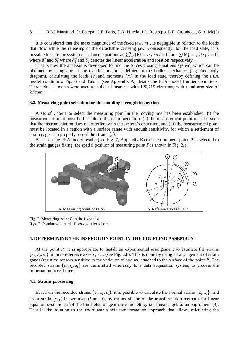
strain gages can properly record the strains . Based on the FEA model results (see Fig. 7, Appendix B) the measurement point P is selected to
the strain gauges fixing, the spatial position of measuring point P is shown in Fig. 2.a.
a. Measuring point position b. Reference axes , , .
Fig. 2. Measuring point P in the fixed jaw
Rys. 2. Pomiar w punkcie szczęki nieruchomej
4. DETERMINING THE INSPECTION POINT IN THE COUPLING ASSEMBLY
At the point , it is appropriate to install an experimental arrangement to estimate the strains in three reference axes , , (see Fig. 2.b). This is done by using an arrangement of strain
gages (resistive sensors sensitive to the variation of strains) attached to the surface of the point . The
recorded strains are transmitted wirelessly to a data acquisition system, to process the
information in real time.
4.1. Strains processing
Based on the recorded strains , it is possible to calculate the normal strains { }, and
shear strain { } in two axes ( and ), by means of one of the transformation methods for linear
equation systems established in fields of geometric modeling, i.e. linear algebra, among others [9].
That is, the solution to the coordinate’s axis transformation approach that allows calculating the
i j
P
k
iP
s
tj
ijr
j
ir
s
t
b. Refecence axes r, s, t.a. Measuring point position.

Operating conditions effect over the coupling strength for urban aerial ropeways 9
corresponding magnitudes of the variables to the strain states { } in the axes and , using the
following expressions
( ),
( ),
( ).
(1)
The strains measurement is obtained on the point surface, therefore, it is a plane strain case,
Figure 2.b shows the status of the strains in the point .
4.2. Experimental test validation
The validation of the experimental test is performed by means of checking between: (i) the test
results in controlled operating conditions; and (ii) the calculation in FEA. The controlled test was
made in quasi-static conditions and it has been performed in the workshop, i.e. the test has been
isolated to external conditions and has the following features [10]: (i) without the wind loads effect;
(ii) without operating frequency, due to a null gondola pod speed; (iii) with a constant temperature and
moisture; and (iv) in the gondola pod, an equivalent of 700kg mass live load is applied. The
calculations in FEA are obtained from a linear static model that emulates the existing conditions in the
controlled test.
In the controlled test, the strain stationary data { } in the point is processed. The FEA
strains { } are computed in a point located analogue to the controlled test. Fig. 3 shows the
Kaplan-Meier cumulative distribution to get a frequency density distribution (PDF) of the controlled
quasi-static test and the strain mean { } ; it also presents the values obtained in FEA { } .
Then, from the { } and { } data, the measurement error, { }
, is calculated as
follows
{
} {
} {
} . (2)
A goodness of fit test was applied to the discrete variables of the controlled test, { } , to
determine the random degree in which it is constructed [14]. The probabilities adjustment establish
that { } come from a set of adjusted distributions to the Gaussian probability (see Fig. 3),
transforming the discrete variables to a continuous-theoretical variables [8], with the density function
of a normal distribution variables, average values and variance values . The normal distribution
fitting is considered valid given that the error values represent an association measurement of the
statistical model with the obtained data [6], which has an acceptable level for the scope of this work.
Then, the results shows that there is an acceptable standard error relative to the fitting parameters (see
Tab. 2), between experimental measurements and the model results from FEA.
Table 2
Normal fitting distribution parameters results
Parameter { }
Log likelihood 4.543E3 4.853E3
Mean [ ] 0.524 0.135
Variance, [ ] 2.059E-6 1.383E-6
Estimate [ ] 0.524 0.135
√ 1.435E-3 1.176E-3
Std. Error 4.821E-5 3.896E-5
√ 3.412E-5 2.757E-5

10 R.M. Martinod, D. Estepa, C.E. Paris, F.A. Pineda, J.L. Restrepo, L.F. Castañeda, G.A. Mejía
Fig. 3. Controlled test (quasi-static conditions)
Rys. 3. Badanie kontrolne (warunki quasi-statyczne)
5. ANALYSIS OF THE RESULTS
The gondola pod was subjected to a journey in commercial conditions in the entire circuit, (called
dynamic conditions), getting the strains in the time domain { } . Then, the set of data is
proceeded to extract the data segments in inter-stations, { } (see Fig. 4). The data
segments { } record the wind loads effects joined up with other parasite external effects
such as: (i) speed variation; (ii) disturbance caused by the entry and exit in the stations by the other
gondolas pod; (iii) passengers movement inside the gondola pod; and (iv) disturbance caused by the
gondolas transit on the towers. The Kaplan-Meier cumulative distribution of a set of strains
{ } is built to analyze the behavior of the sampled signals, which represent the
description of the record in statistical terms (see Fig. 5); besides, it is shown the overlap of the signals
{ } by means of two histograms: (i) the gondola in controlled test { } , described in the
previous section; and (ii) the gondola in commercial conditions { } . Due to the
frequency histogram is characteristic of a normal distribution, it is estimated the average
{[ ] [ ] }, as a measure of central tendency. In addition, it is possible to calculate the
standard deviation {√ } {[ ] [ ] }, as the dispersion of the measured signals caused
by the effect of the wind loads and other external conditions.
Operating conditions effect over the coupling strength for urban aerial ropeways 11
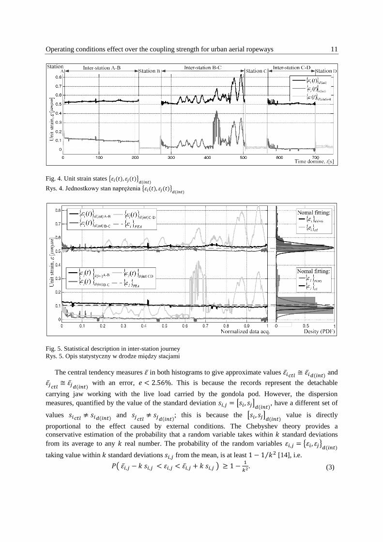
Fig. 4. Unit strain states { }
Rys. 4. Jednostkowy stan naprężenia { }
Fig. 5. Statistical description in inter-station journey
Rys. 5. Opis statystyczny w drodze między stacjami
The central tendency measures in both histograms to give approximate values
and
with an error, . This is because the records represent the detachable
carrying jaw working with the live load carried by the gondola pod. However, the dispersion
measures, quantified by the value of the standard deviation [ ] , have a different set of
values
and
; this is because the [ ] value is directly
proportional to the effect caused by external conditions. The Chebyshev theory provides a
conservative estimation of the probability that a random variable takes within standard deviations
from its average to any real number. The probability of the random variables { }
taking value within standard deviations from the mean, is at least ⁄ [14], i.e.
( )
. (3)

12 R.M. Martinod, D. Estepa, C.E. Paris, F.A. Pineda, J.L. Restrepo, L.F. Castañeda, G.A. Mejía
Therefore, around 99.7% of all the values from a normal distributed sample are within from
the mean [8], commonly known as the three-sigma rule, . With it
is possible to infer, with a 99.7% certainty, that in the fixed jaw:
(i) the maximum external excitation in direction is ; and
(ii) the maximum external excitation in direction is .
6. CONCLUSIONS AND FUTURE WORK
The standard deviation { } , as a statistical index applied to the strains { }
,
is a sensitive index to record the effect caused by external shocks, by the effect of the wind loads and
other parasite external effects such as: (i) speed variation; (ii) disturbance caused by the entry and exit
in the stations by the other gondolas pod; (iii) passengers movement inside the gondola pod; and (iv)
disturbance caused by the gondolas transit on the towers.
The proposed methodology can be used in operational conditions in each gondola pod. By defining
a two standard deviations criterion (three-sigma rule), it is possible to classify the effect caused by
external shocks: (i) in the case that the value of ( ), there is a relevant effect of
disturbances due to the extreme conditions; or (ii) in the event that the histograms are similar
( ), it means that the effect of disturbances due to the extreme conditions, is not significant.
The proposed methodology gives the possibility of automating the process of ongoing inspection of
the external excitation, for assessing the journey safety of a passenger cable car of urban transportation
on aerial ropeways.
The proposed methodology is useful whereas the data logging allows getting information in
commercial operation, avoiding measurements that require downtime for the system inspection.
The recorded signals allow the statistics analysis that can be used for maintenance planning; this
means that the proposed procedure represents the technological basis for the development of the
condition-based maintenance.
There is a clear feasibility to implement the proposed procedure for the entire fleet of aerial cable
cars of urban aerial ropeway systems, because: (i) the sensors and data acquisition systems are widely
studied for technical elements that do not represent a challenge to the current industrial sector; (ii) the
costs of implementation are low in relation to the amount of information that the process may obtain
from the system.
This paper opens to different research fields due to elements that can be considered for future
publications: (i) to study the short pulses –with high frequency components– in signal; (ii) to study
the cable load and strain relative to the excitation frequencies effect; (iii) to study the relationship
between the variation and the aerial cable car faults to identify the technical state in commercial
conditions.
References
1. Bathe, K.J. Finite Element Procedures. New Jersey, USA: Prentice Hall. 1996.
2. Bryja, D. & Knawa, M. Computational model of an inclined aerial ropeway and numerical method
for analyzing nonlinear cable-car interaction. Computers and Structures. 2011. Vol. 89. No. 21.
P. 1895-1905.
3. Degasperi, F. Measurement of dynamic stresses on carriers with detachable grip at station entrance:
LA.T.I.F. experiences and future prospects. In: 8th International Congress for Transportation by
Rope (OITAF). 1999. P. 107-133.
4. Doppelmayr, A. Conceptual inputs for optimizing the functional efficiency of circulating
monocable ropeways: project engineering, design and operation in a safety management control
loop based on incident analysis. Austria: WIR Public. 1998.

Operating conditions effect over the coupling strength for urban aerial ropeways 13
5. Genta, G. Vibration Dynamics and Control. Torino, Italy: Springer Science Business. 2009.
6. Grant, E.L. Statistical Quality Control. USA: McGraw Hill. 1964.
7. Hoffmann, K. Recent developments in cable-drawn urban transport systems. FME Transactions.
2006. Vol. 34. No. 4. P. 205-212.
8. Levin, R.I. & Rubin, D.S. Statistics for management. USA: Pearson. 2004.
9. O'Neil, P.V. Advanced Engineering Mathematics. Australia: Thomson. 2003.
10. Petrova, R. & Karapetkov, St. & Dechkova, S. & Petrov, P. Mathematical Simulation of Cross-
Wind Vibrations in a Mono-Cable Chair Ropeway. Procedia Engineering. 2011. Vol. 14. P. 2459-
2467.
11. Pomagalski, S.A. Device for monitoring the spring force exerted by spring actuated bar coupled
cable clamps for chair lifts and cable cars. United States Patent and Trademark Office.
US4665755: 1985.
12. Pomagalski, S.A. Chairlift or gondola-lift having a friction-based driving device for chairs or cars.
United States Patent and Trademark Office. US5188037: 1993.
13. Pomagalski, S.A. Device for remote measurement of clamping force of cable car or chair lift
support cable clamp. Institut National de la Propriété Industrielle. France. FR2750764-A1: 1996.
14. Walpole, R. & Myers, R. & Myers, S. & Keying, Y. Probability & statistics for engineers &
scientists. USA: McGraw-Hill. 2011.
15. Zienkiewicz, O.C. & Morgan, K. Finite Elements & Approximation. USA: Dover Publications.
2006.
Appendix A. Boundary conditions applied to FEA model.
Fig. 6. Fixed jaw boundary conditions
Rys. 6. Stałe warunki brzegowe szczęki
Table 3
Fixed jaw boundary conditions
Load Value Direction cosines [deg]
i j k
[kN] 8.62 110 150 70
[kN] 14.5 90 0 90
[kN] 76.9 0 90 90
[kN] 21.5 90 0 90
[kN m] 05.2 90 90 0
00.0 - - -

14 R.M. Martinod, D. Estepa, C.E. Paris, F.A. Pineda, J.L. Restrepo, L.F. Castañeda, G.A. Mejía
Appendix B. FEA planar strain flow.
a. axis direction strain flow.
b. axis direction strain flow.
Fig. 7. Fixed jaw strain flow
Rys. 7. Rozkład naprężeń w szczęce stałej
Received 23.04.2013; accepted in revised form 25.08.2014