operating instruction manual - 2helpuoperating instruction manual pa3500ex ... installation tools,...
TRANSCRIPT
- 16
56
51
56
1--PA 3500E XPA 3500E XPA 3500E XPA 3500E XPA 3500E X
- 16
56
51
56
1--
MODEL PA3500EX
OPERATING INSTRUCTION MANUAL
PA3500EX
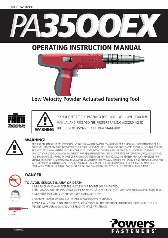
Low Velocity Powder Actuated Fastening Tool
DO NOT OPERATE THE PA3500EX TOOL UNTIL YOU HAVE READ THIS
MANUAL AND RECEIVED THE PROPER TRAINING ACCORDING TO
THE CURRENT AS/NZS 1873.1:1994 STANDARDWARNING
WARNING!PRIOR TO OPERATING THE PA3500EX TOOL, STUDY THIS MANUAL CAREFULLY AND DEVELOP A THOROUGH UNDERSTANDING OF THECONTENTS. PROPER TRAINING ACCORDING TO THE CURRENT AS/NZS 1873.1 :1994 STANDARD, SAFETY REQUIREMENTS FOR POWDERACTUATED FASTENING SYSTEMS MUST BE COMPLETED. STATE, LOCAL, OR OTHER REGULATIONS SHOULD ALSO BE FOLLOWED.CONTACT YOUR LOCAL WORKCOVER AUTHORITY FOR REQUIREMENTS APPLYING IN YOUR STATE OR TERRITORY. LAWS, REGULATIONS,AND STANDARDS REGARDING THE USE OF POWDER ACTUATED TOOLS MAY PERIODICALLY BE REVISED. ANY SUCH REVISIONS MAYCHANGE THE SAFETY AND OPERATING PROCEDURES DESCRIBED IN THIS MANUAL. POWERS FASTENERS IS NOT RESPONSIBLE FOR ANYSUCH REVISIONS WHICH OCCUR AFTER PUBLICATION OF THIS MANUAL. IT IS THE RESPONSIBILITY OF THE USER TO MAINTAINFAMILIARITY WITH THE CURRENT LAWS, REGULATIONS, AND STANDARDS THAT APPLY TO THE POWDER ACTUATED TOOL.
DANGER!
TO AVOID SERIOUS INJURY OR DEATH:NEVER PLACE YOUR HAND OVER THE MUZZLE WITH A POWDER LOAD IN THE TOOL.IF THE TOOL ACCIDENTALLY DISCHARGES THE PISTON OR FASTENER MAY PENETRATE YOUR HAND RESULTING IN SERIOUS INJURY.
NEVER CLOSE TOOL WITH ANY PART OF HAND OVER MUZZLE END.
OPERATORS AND BYSTANDERS MUST WEAR EYE AND HEARING PROTECTION.
ALWAYS ASSUME TOOL IS LOADED. DO NOT PLACE A FINGER ON THE TRIGGER OF LOADED TOOL UNTIL MUZZLE END ISAGAINST WORK SURFACE AND YOU ARE READY TO MAKE A FASTENING.

MODEL PA3500EX
2
INTRODUCTIONThank you for purchasing the Powers new PA3500EX low velocity powder actuated tool. This tool will provide youwith excellent performance provided the steps for proper operation and maintenance are followed. Powder actuatedfastening systems can provide a cost effective method of attaching fixtures for light duty, static load conditions. Thesystems provided by Powers Fasteners consist of specially designed fasteners, installation tools, and powder loadswhich are designed to function in combination to provide optimum performance. While powder actuated tools canprovide one of the fastest and economical means of fastening, they can also be dangerous if they are not operatedproperly.
Prior to operating the PA3500EX tool, you must be properly trained in the operation and maintenance of this tool Aspart of the training process, you should read and understand the contents of this instruction manual especially thesafety precautions.
Powder actuated tools may be operated only by properly trained operators as described in AS/NZS 1873.1 :1994Standard, Safety Requirements for Powder Actuated Fastening Systems. For complete tool operation details, contactyour local Powers Fasteners Branch office or distributor for training.
Remember, safety begins with you! It is your primary responsibility when operating this tool. Failure to follow theproper operating, maintenance, and safety procedures can result in serious injury or death to yourself or bystanders. Inaddition to the training provided, you should be familiar with any local, state, and federal regulations. If you have anyquestions which are not covered in this manual, contact your local Powers Fasteners Branch office or distributor.
TOOL DESCRIPTIONThe PA3500EX is a high quality low velocity, semi automatic tool which can be used to install 7.6mm head drive pins,8mm head drive pins, and 1/4"-20 threaded studs up to 75mm in total length. Designed for high speed and repetitivevolume applications, the tool features an automatic .27 caliber strip load advance system, an engineered plastic,heavy duty tool body, a rubber handle pad to minimize the effects of recoil and powder adjustment.
In order to drive the fastener into the base material, the tool operates using the indirect acting piston principle. ThePA3500EX tool uses the impact principle in which an internal drive piston impacts the fastener to drive it into thebase material.
With this method, the piston is positioned at the rear of the tool barrel prior to actuation and is not in contact withthe fastener. When the tool is fired, the expanding gasses of an ignited .27 caliber powder load drive the pistonforward in the barrel. As the piston continues its forward travel, the tip of it impacts the fastener driving it into thebase material.
Safety mechanisms incorporated into the tool include:
• Free Flight Safety – The tool can only be fired if the barrel/fastener guide is fully depressed against the worksurface.
• Drop Fire Safety – A specially designed sear pin prevents the firing pin from striking the powder load if the tool isdropped.
• Accidental Firing Safety – Two distinct and separate operations must be performed to actuate the tool. First, thebarrel/fastener guide must be depressed against the work surface, then the trigger must be pulled.
- 16
56
51
56
1--PA 3500EXPA 3500EXPA 3500EXPA 3500EX
Power adjustment Trigger Stop
Engineered Plastic
Rubber Handle Pad
Rubber Handle Pad
Fastener Guide
MODEL PA3500EX
POWER ADJUSTMENTThe power adjustment mechanism of the PA3500EX allows the user to adjust the penetration of the pin through thefixture ensuring a precise fixing. To operate the power adjustment mechanism, move the regulating wheel which issituated on the PA3500EX housing in the + or – direction to increase or decrease the power of the tool thusadjusting the pin penetration.
ADJUST THE DRIVING POWER BY TURNING THE REGULATING WHEEL.1 = minimum power
3 = medium power
6 = maximum power
Note: 1) Start with minimum power. If the fastener does not penetrate deep enough,increase the power.2) For 75mm pins, use power level 5 or higher.
TECHNICAL DATATool Body: Engineered Plastic
Tool Length: 370mm
Tool Weight: 2.3kg
Pin Type: .300 (7.6mm) Head Drive Pin
8mm Head Drive Pin
1/4"-20 Threaded Stud
Pin Length: 13mm to 75mm Total Length
Load Type: .27 Caliber in a 10 Load Strip
Power Level: Green (3), Yellow (4), Red (5)
FASTENER FUNCTIONINGPrior to learning the safe operating procedures for this tool, it is important to understand how a powder actuatedfastener works. A powder actuated fastener is considered to be a direct drive or forced entry type of fastener becauseit is driven directly into the base material. The driving action causes tremendous forces to be applied to the fastener.Powers powder actuated fasteners are specially designed and manufactured using an austempering process towithstand the forces imposed during the driving operation. Only fasteners manufactured or supplied by PowersFasteners should be used in this tool.
3

MODEL PA3500EX
4
FUNCTIONING IN CONCRETEThe performance of a powder actuated fastener when installed into concrete or masonry base materials is based onthe following factors:
1. Strength of the base material
2. Hardness and concentration of the aggregate
3. Shank diameter of the fastener
4. Depth of embedment into the base material
5. Fastener spacing and edge distance In addition to these factors, installation tool accessories such as a stop spallwhich reduces the tendency of the concrete surface to spall during the driving action can increase the performance ofthe fastener.
When a powder actuated fastener is driven into concrete, it displaces the volume of concrete around the embeddedarea of the fastener shank. As this occurs, the concrete directly surrounding the fastener is compressed and in turnpresses back against the shank of the fastener.
Additionally, the driving action generates heat which causes particles within the concrete to fuse to the shank of thefastener. This combination of compression and fusion holds the fastener in the concrete base material.A similar actionoccurs when fastening into block masonry.
Generally, the performance of the fastener in a given concrete strength will increase with greater embedment depthsin a certain range. Depending on the fastener style and base material strength, embedment depths range from 16mmto 38mm For depths greater than this range, there is the possibility of fastener bending or fishhooking which maydecrease expected load capacities and create a safety hazard.
During the driving action, some localized surface spalling of the concrete may occur. Normally, this is a surface effectwhich does not effect the performance of the fastener. However, it may pose an aesthetic problem for exposedapplications where a fixture is not used. In cases such as this, two methods can be used to improve the appearanceof the fastening. A stop spall adapter mounted on the powder actuated tool can help to reduce surface spalling.Another method used is to drive the fastener through a steel washer to improve the appearance of the application.
FUNCTIONING IN STEELThe load performance of a powder actuated fastener when installed into steel base materials is based on thefollowing factors:
1. Thickness of the steel
2. Tensile strength of the steel
3. Shank diameter of the fastener
4. Depth of point penetration through the steel
5. Fastener spacing and edge distance.
When a powder actuated fastener is driven into steel, it displaces the steel laterally 360° around the shank of thefastener. Since steel is an elastic material, it presses back against the shank of the fastener to hold it in place. As thediameter of the fastener shank is increased, the load capacity obtained will generally increase provided the steelthickness is sufficient to accept the fastener. To further increase fastener performance in steel, some fasteners have aknurled shank which allows the steel to form a key lock into the grooves to provide higher capacities than thoseobtained with a smooth shank. For optimum performance, the fastener point should completely penetrate the steel.Normally, a minimum of 6.5mm is allowed for the point length. An increase in performance can be expected until thefastener no longer completely penetrates through the steel. At this point, the elastic properties of the steel cause acompression force to be developed at an angle against the fastener point which reduces load capacity. In thicker steelbase materials, adequate load capacities may be obtained for applications in which the point of the fastener does notfully penetrate the steel. Job site performance tests are recommended.
Fasteners should not be used in areas that have been welded or cut with a torch as these procedures may havecaused local hardening of the steel. Over driving of the fastener should be avoided as the rebound created mayreduce the load capacity or cause damage to the fastener.
When fastening into unsupported long steel members, it may be necessary to provide support in the area of thefastening to prevent spring action which can cause inconsistent penetration and a reduction in load capacity.
������������������������������������������������������������������������������������������������������������������������������������������������������������������������������yyyyyy
����������������������������������������������������������������������������������������������������������������������������������������������������������������������������������������������������������������������������������������yyyyyyyy��������������������������������������������������������������������������������������������������������������������yyyy
Washer
��
����������������������������������������������������������yy����������������������������������������������������������yy����������������������������������������������������������yy����������������������������������������������������������yy����������������������������������������������������������yy����������������������������������������������������������yy
����������������������������������������������������������������������������������������������������������������������������������������������������������������������������������������������������������������������������������������yyyyyyyy��������������������������������������������������������������������������������������������������������������������yyyy
Stop Spall
����������������������������������������������������������yy����������������������������������������������������������yy����������������������������������������������������������yy����������������������������������������������������������yy����������������������������������������������������������yy����������������������������������������������������������yy��

MODEL PA3500EX
SUITABLE BASE MATERIALWhile powder actuated fasteners can be used successfully in concrete, certain masonry materials, and some types of steel arecompletely unsuitable.
Fasteners should never be fired into hard or brittle materials such as cast iron, tile, glass, or rock. These materials can shattereasily resulting in a potential safety hazard. In addition, soft base materials such as wallboard,
plaster, or wood are not appropriate as the fastener could pass completely through these materials. The user should never guesswhen fastening into any base material. Failure to follow the recommended installation and safety guidelines can result in severeinjury or death to the tool operator and/or bystanders.
CENTER PUNCH TESTA center punch test should always be performed to determine the suitability of the base material for a powder actuatedfastening. This test is relatively simple and can help to insure a safe, successful fastening. Be sure to wear the appropriate eyeprotection when performing this test.
To begin, select the fastener to be used for the job. Then,
place the point of the fastener against the proposed base material. Strike the fastener with a single hammer blow,
then examine the point. If the point of the fastener is not blunted and the base material has a clear point indentation, it isacceptable to proceed with the first test installation.
Use of a powder actuated system is not recommended if the following occurs during the center punch test:
1. The fastener point has been blunted. This indicates that the base material is too hard.
2. The base material cracks or shatters. This indicates that the base material is too brittle.
3. When using an average hammer blow, the fastener penetrates the base material easily. This indicates that the base material istoo soft.
FASTENER INSTALLATION REQUIREMENTSIt is important to understand the required minimum base material thickness requirements along with the minimum spacing andedge distance requirements. Failure to follow these requirements can result in an unsuccessful fastening and create a safetyhazard.
BASE MATERIAL THICKNESSConcrete base material should be at least three (3)
times as thick as the fastener embedment penetration.
If the concrete is too thin, the compressive forces forming at the fasteners point can cause the free face of the concrete to breakaway. This can create a dangerous condition from flying concrete and/or the fastener and also results in a reduction of fastenerholding power. For applications in the face shell of concrete masonry block,
select a fastener length which will not exceed the thickness of the face shell.
FASTENER PENETRATION GUIDEThe following table lists typical embedment or penetration depths expected in the base materials listed.
The penetration will vary depending on the density of the material. This table should be used as a guide since the consistency ofthese materials varies. When in doubt, a job site performance test should be conducted.
DENSITY TYPICAL BASE MATERIAL PENETRATION
Soft Masonry Concrete block 25-32mm
Average Poured concrete concrete 19-25mm
Dense concrete Pre-stressed/pre-cast concrete 16-19mm
EDGE DISTANCEDo not fasten closer than 75mm from the edge of concrete. If the concrete cracks, the fastener may not hold. Closer edgedistances for applications such as sill plates may be permitted if specific fastener testing has been conducted.
5
Penetration
3xPenetration
������������������������������
������������������������������
������������������������������
������������������������������
������������������������������
������������������������������
������������������������������
������������������������������
������������������������������
������������������������������
������������������������������
������������������������������
������������������������������
������������������������������
������������������������������
������������������������������
������������������������������
������������������������������
������������������������������
������������������������������
������������������������������
������������������������������
������������������������������
������������������������������
������������������������������
������������������������������
������������������������������
������������������������������
������������������������������
yyyyyyyyyyyyyyyyyyyyyyyyyyyyyy
Point Flattens
No Indent
������������������������������
������������������������������
������������������������������
������������������������������
������������������������������
������������������������������
������������������������������
������������������������������
������������������������������
������������������������������
������������������������������
������������������������������
������������������������������
������������������������������
������������������������������
������������������������������
������������������������������
������������������������������
������������������������������
������������������������������
������������������������������
������������������������������
������������������������������
������������������������������
������������������������������
������������������������������
������������������������������
������������������������������
������������������������������
yyyyyyyyyyyyyyyyyyyyyyyyyyyyyy
Surface Shatters
Material Cracks
������������������������������
������������������������������
������������������������������
������������������������������
������������������������������
������������������������������
������������������������������
������������������������������
������������������������������
������������������������������
������������������������������
������������������������������
������������������������������
������������������������������
������������������������������
������������������������������
������������������������������
������������������������������
������������������������������
������������������������������
������������������������������
������������������������������
������������������������������
������������������������������
������������������������������
������������������������������
������������������������������
������������������������������
������������������������������
yyyyyyyyyyyyyyyyyyyyyyyyyyyyyy
Fastener Sinks in with Average Hammer Blow
1
2
3
������������������������������������������������������������������������������������������������������������������������������������������������������������������������������yyyyyy3"75

MODEL PA3500EX
6
SPACINGSetting fasteners too close together in concrete or masonry can cause cracking. The recommended minimum distancebetween fasteners is 75mm center to center.
FASTENER LENGTH SELECTION IN CONCRETEFor permanent applications using pins in concrete, first determine the thickness of the fixture to be fastened. To this,add the required embedment or penetration into the base material. This will be the fastener shank length required.For applications in the face shell of masonry block, select a fastener length which will not exceed the thickness of theface shell.
For removable applications with threaded studs, the shank length required is equal to the embedment depthrequired. To determine the minimum threaded length, add the thickness of the fixture and the nut / washer thickness.
The nut and washer thickness is equal to the nominal thread diameter. Do not over tighten threaded parts.
Maximum tightening torque values are listed in the table below. Use of a nut setter is recommended to reduce thepossibility of over tightening the fasteners. For critical applications, perform a job site test.
MAXIMUM TORQUE FOR 1/4" STUD (Nm)
3
INSTALLATION IN STEELThe following guidelines are based on the installation of a fastener in structural steel with the point fully penetratingthe steel member. Recommended steel material thickness ranges from a minimum of 3mm to a maximum of 10mmFor use in higher strength structural steel, applications where the point does not penetrate the steel member, or athickness of steel greater than 10mm,
job site performance tests are recommended.
BASE MATERIAL THICKNESSSteel base materials should be a minimum of 3mm in thickness.
EDGE DISTANCEFor installations in steel, 13mm is the recommended minimum edge distance.
SPACINGThe recommended minimum distance between fastenings is 38mm center to center for installations in steel
FASTENER LENGTH SELECTION IN STEELFor permanent applications when using pins in steel, first determine the thickness of the fixture to be fastened.
To this, add the thickness of the steel base material plus a minimum of 6.5mm to allow for proper point penetration.
This will be the minimum fastener shank length required.
Do not select a fastener length longer than that required for the application. An excessively long shank can burnish orpolish the hole created in the steel resulting in a reduction in load capacity.
For removable applications with threaded studs, the shank length required is equal to the thickness of the steel basematerial plus a minimum of 6.5mm to allow for proper point penetration. This will be the minimum fastener shanklength required. Do not select a shank length longer than that required for the application.An excessively long shankcan burnish or polish the hole created in the steel resulting in a reduction in load capacity. To determine the minimumthreaded length, add the thickness of the fixture and the nut / washer thickness.
The nut and washer thickness is equal to the nominal thread diameter.
Do not over tighten threaded studs. The maximum tightening torque is listed in the table below. Use of a nut setter isrecommended to reduce the possibility of over tightening the fasteners. For critical applications, perform a job sitetest.
BASE STEEL THICKNESS (mm) MAXIMUM TORQUE FOR 1/4" STUD (Nm)3mm 3
5mm 5
6.5mm 8
10mm 11
������������������������������������������������������������������������������������������������������������������������������������������������������������������������������yyyyyy3"
��������������������
��������������������
��������������������
��������������������
��������������������
��������������������
��������������������
��������������������
��������������������
��������������������
��������������������
��������������������
��������������������
��������������������
��������������������
��������������������
��������������������
��������������������
��������������������
��������������������
��������������������
��������������������
��������������������
��������������������
��������������������
��������������������
��������������������
��������������������
��������������������
yyyyyyyyyyyyyyyyyyyy�����������������������������y Fixture
Embedment
��������������������
��������������������
��������������������
��������������������
��������������������
��������������������
��������������������
��������������������
��������������������
��������������������
��������������������
��������������������
��������������������
��������������������
��������������������
��������������������
��������������������
��������������������
��������������������
��������������������
��������������������
��������������������
��������������������
��������������������
��������������������
��������������������
��������������������
��������������������
��������������������
yyyyyyyyyyyyyyyyyyyy
Thread Length
Embedment
75
��1/8"
����
1/2"
������
1-1/2"
�����
��
13mm
38mm
3mm
MODEL PA3500EX
7
FASTENER AND POWDER LOAD SELECTION GUIDEThis tool should only be used with the fasteners and powder loads supplied by Powers Fasteners. Use of otherproducts may create a safety hazard and will void the tool warranty.
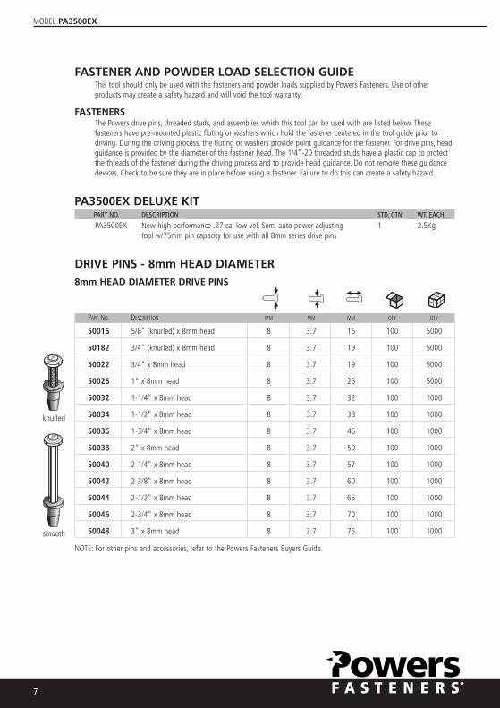
FASTENERSThe Powers drive pins, threaded studs, and assemblies which this tool can be used with are listed below. Thesefasteners have pre-mounted plastic fluting or washers which hold the fastener centered in the tool guide prior todriving. During the driving process, the fluting or washers provide point guidance for the fastener. For drive pins, headguidance is provided by the diameter of the fastener head. The 1/4"-20 threaded studs have a plastic cap to protectthe threads of the fastener during the driving process and to provide head guidance. Do not remove these guidancedevices. Check to be sure they are in place before using a fastener. Failure to do this can create a safety hazard.
PA3500EX DELUXE KITPART NO. DESCRIPTION STD. CTN. WT. EACH
PA3500EX New high performance .27 cal low vel. Semi auto power adjusting 1 2.5Kg.tool w/75mm pin capacity for use with all 8mm series drive pins
DRIVE PINS - 8mm HEAD DIAMETER8mm HEAD DIAMETER DRIVE PINS
PART NO. DESCRIPTION MM MM MM QTY QTY
50016 5/8" (knurled) x 8mm head 8 3.7 16 100 5000
50182 3/4" (knurled) x 8mm head 8 3.7 19 100 5000
50022 3/4" x 8mm head 8 3.7 19 100 5000
50026 1" x 8mm head 8 3.7 25 100 5000
50032 1-1/4" x 8mm head 8 3.7 32 100 1000
50034 1-1/2" x 8mm head 8 3.7 38 100 1000
50036 1-3/4" x 8mm head 8 3.7 45 100 1000
50038 2" x 8mm head 8 3.7 50 100 1000
50040 2-1/4" x 8mm head 8 3.7 57 100 1000
50042 2-3/8" x 8mm head 8 3.7 60 100 1000
50044 2-1/2" x 8mm head 8 3.7 65 100 1000
50046 2-3/4" x 8mm head 8 3.7 70 100 1000
50048 3" x 8mm head 8 3.7 75 100 1000
NOTE: For other pins and accessories, refer to the Powers Fasteners Buyers Guide.
knurled
smooth
MODEL PA3500EX
8
POWDER LOAD SELECTIONUse of the proper power level is critical to the success of a powder actuated fastening. Prior to selecting the properpower level, conduct a center punch test as described in the section on base material suitability.
To select the proper power level to be used with a specific fastener, always make a test firing using the lowest powerlevel recommended for the tool being used. If the lowest power level does not fully drive the fastener, try a powderload having the next higher power level. Continue this procedure until the proper fastener penetration is obtained.
Powers Fasteners loads are specifically designed for use in the PA3500EX tool. Do not use any other type of load.
Failure to follow this instruction may cause accidental load discharge, damage to the tool, and cause serious injury ordeath to the operator or bystanders.
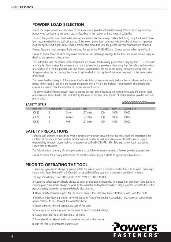
The PA3500EX uses .27 caliber short crimped rim fire powder loads having power levels ranging from 3 - 5. The loadsare supplied 10 to a strip. The crimped tip on the load retains the powder in the casing. Rim fire refers to the methodof actuation. In a rim fire powder load, the primer is contained in the rim of the casing. When the tool is fired, thefiring pin strikes the rim causing the primer to ignite which in turn ignites the powder contained in the main portionof the load.
The power level or strength of the powder load is identified using a color code and numbers as shown in the tablebelow. Power level 3 / green is the lowest and power level 5 / red is the highest. A combination of numerals andcolours are used in case the operator has colour deficient vision.
The power level of Powers powder loads is marked on each box of loads.As the number increases, the power levelalso increases. Power level is also indicated by the color of the box, label, the tip of each individual powder load, andplastic strip.
SAFETY STRIPPART NO. POWER LOAD LOAD COLOUR SIZE STD.BOX STD CTN. MASTER CTN.
50622 3 Green .27 strip 100 1000 10000
50626 4 Yellow .27 strip 100 1000 10000
50630 5 Red .27 strip 100 1000 10000
SAFETY PRECAUTIONSSafety is your primary responsibility when operating any powder actuated tool. You must read and understand thecontents of this manual. You must be familiar with all functional and safety requirements of the tool. It is yourresponsibility to obtain proper training in accordance with AS/NZS1873:1994. Existing state or local regulationsshould also be followed.
The following is a summary of safety precautions to be followed when operating a Powers powder actuated tool.
Failure to follow these safety instructions can result in serious injury or death to operators or bystanders.
PRIOR TO OPERATING THE TOOL1. Warning signs should always be posted within the area in which a powder actuated tool is to be used. These signsshould be at least 500mm(W) x 300mm(H) in size with boldface type that is not less than 30mm in height.
The sign should state "CAUTION – EXPLOSIVE POWERED TOOL IN USE”.
2. Approved safety goggles should always be worn by operator or bystander, to protect their eyes from flying particles.Hearing protection should always be worn by the operator and bystanders when using a powder actuated tool. Otherpersonal safety protection as required should also be used.
3. Never modify or fabricate parts for use in your Powers tool. Use only Powers fasteners, loads, and tool parts.
4. Hands or other body parts must never be placed in front of muzzle/barrel. Accidental discharge can cause pistonand/or fastener to pass through the operator’s hand.
5. Never compress the tool against any part of the body.
Serious injury or death may result in the event of an accidental discharge.
6. Always point tool in a safe direction at all times.
7. Tools should be cleaned and maintained as directed in this manual.
8. Use the tool for its intended purpose only.

MODEL PA3500EX
9
PREPARATION FOR LOADING THE TOOL1. Tools must be checked prior to operating to make sure they are not fully or partially loaded with a powder load orfastener.
2. To insure safe operation, perform the daily function test described in this manual. Be sure the tool is not loadedprior to performing this test.
3. Do not operate this tool unless all its parts are in place and operating appropriately. Never attempt to use amalfunctioning tool.
4. Never guess about the suitability of a base material. If you are uncertain about the suitability of a base material,perform a center punch test.
5. Do not operate the tool until you learn and understand the color code / numbering system used to identify thepower level of powder loads.
OPERATING THE TOOL1. Only use fasteners and powder loads designed for this tool as supplied by Powers Fasteners.
2. Do not use powder actuated tools in a flammable or an explosive atmosphere.
3. Do not fire a tool without a fastener. The piston will impact the work surface possibly causing serious injury to theoperator or bystanders along with damage to the tool.
4. Do not load the tool until you are ready to make a fastening. Check the power load level before inserting it intothe tool chamber.
5. Fastener must be loaded prior to loading the powder load, to prevent injury to operator or bystander in the eventof an accidental discharge.
6. Do not close tool against work surface. The tool should be manually closed, with hand away from muzzle/barrel toprevent accidental discharge.
7. Hold the tool perpendicular to the work surface at all times. Use a spall guard wherever possible. This will limit thepossibility of fastener ricochet which could cause serious injury or death to the operator or bystanders.
8. Always perform a test fastening with the lightest load level designed for use in the tool. If the lightest load fails toset the fastener, try the next highest load until the proper level is attained. Failure to follow this procedure may causethe fastener to be overpowered.
If this occurs, the fastener may fully penetrate the base material causing serious injury or death to someone.
Overpowering the fastener can also damage the tool,
creating a safety hazard to both the operator or bystanders.
9. Do not fasten into cast iron, tile, glass, or other types of brittle materials. These materials can shatter and createsharp fragments which may cause injury.
10. Do not fire tool within 75mm (three inches) of the edge of a concrete base material or within 13mm (onehalfinch) of the edge of a steel base material.
11. Do not attempt to install a fastener closer than 75mm
(three inches) to another previously inserted fastener in concrete or 38mm (one and one-half inch) in steel.
12. Do not fasten into a concrete base material less than 3 times as thick as the fastener penetration or into a steelbase material thinner than 3mm.
13. Never attempt to install a fastener in a cracked or spalled area in concrete. Place fastener at least 150mm
(six inches) away from a spalled area to prevent the possibility of the fastener bending and striking an operator orbystander.
14. Do not attempt to install fasteners in areas that have been welded or cut with a torch as these procedures mayhave caused local hardening of the steel.
15. Do not fasten through a predrilled hole unless proper guidance is provided.
16. If you decide not to make a fastening after the tool has been loaded, you must always remove the powder loadfirst followed by the fastener.
17. Never attempt to override the safety features of this tool

MODEL PA3500EX
10
HANDLING THE TOOL AND POWDER LOADS1. Never leave a loaded tool unattended. Once the tool is loaded, make the fastening immediately or unload the tool.
2. Always unload the tool before work breaks, changing parts, cleaning or servicing, and when storing.
3. To prevent accidental discharge of loads, never carry the powder loads in the same container as the fasteners or other hardobjects.
4. Always store the powder loads in the containers provided or in an enclosure provided for them. Never intermix the variouspower levels. Keep them segregated in clearly identified containers.
5. Powder loads should never be used in firearms. They are normally more powerful that the cartridges supplied with thefirearms.
6. Powder actuated tools and powder loads should always be stored under lock and key. Tools must be unloaded when not inuse.
TOOL MALFUNCTION1. In the event that a load fails to discharge after the trigger is pulled, the tool must be kept depressed against the work surfacefor a minimum of 30 (thirty) seconds in case of a delayed load discharge. Then carefully remove the entire load strip and disposeof it in a can of water or other nonflammable liquid. Never attempt to force or pry a load out of a tool chamber.
2. Never discard unfired powder loads into a trash container.
3. Do not attempt to unload or disassemble a jammed,
stuck or broken tool as improper handling may cause it to discharge and strike operator and/or bystander.A jammed tool mustbe pointed in a safe direction at all times. Tag the tool and lock it up. Call your Powers Fasteners representative for properassistance.
TOOL OPERATION
CAUTION:Be sure to read and understand all of the safety precautions and training in this manual before attempting to operate the tool.
(Check to be sure the tool is not loaded, the piston moves freely within the barrel, and no foreign objects or fasteners are in thebarrel.) Perform the daily function test before using the tool.
OPERATION1. Always load the fastener before inserting powder load to prevent injury to the operator or bystanders in the event ofan accidental discharge. Place the fastener, point out, into the end of the guide until the fluted tip fits inside. Do not useexcessive force when inserting the fastener. If excessive force is required, stop and determine why the fastener can notbe inserted.
Correct the problem before proceeding.
Note: Do not use fasteners longer than 75mm as listed in the fastener selection section of this manual.
2. Always point the tool in a safe direction away from bystanders and the operator. In one movement, slide the barrelforward then close it against the stop. The barrel should be pulled fully forward to reset the piston for the next fastening.Loss of power may result from an improperly positioned piston.
Do not attempt to close the tool by exerting force on the front of the barrel. Never place your fingers or hands overmuzzle end of the tool. The safe position for hands and fingers are as shown in the diagram.
Hands must never be placed in front of the tool muzzle or barrel. In the event of an accidental discharge, the pistonand/or fastener can pass through the operator's hand.
- 16
56
51
56
1--PA 3500EXPA 3500EXPA 3500EXPA 3500EXPA 3500EX

MODEL PA3500EX
11
3. Insert the powder load strip into the bottom of the tool handle starting with the lowest power level, 3/Green.The strip should be inserted completely and should be flush with the bottom of the handle. Always insert thestrip from the bottom of the handle. Set the power adjustment level to 1. If the fastener does not fully set in thebase material increase the power level to 2 and so on until proper penetration is achieved. If proper penetrationis not achieved using 3/green charge and power level 3, the next strongest charge should be used. Operatorshould then follow the above procedure regarding power level adjustment until proper penetration is achieved.
Note: Over driving or over powering a fastener can cause a safety hazard.
4. To make a fastening, place the tool against the work surface. Hold the tool firmly with two hands andcompletely depress the barrel. Then squeeze the trigger.
Always hold the tool perpendicular to the work surface.
Hold the tool firmly against the work surface to avoid excessive recoil. Never depress the tool against anythingexcept the work surface.
Note: In the event that the load does not discharge after the trigger is pulled, continue to hold the tool depressedagainst the work surface for at least 30 (thirty) seconds in case of a delayed load discharge.
Then carefully remove the entire load strip and dispose of it in a can of water or other non flammable liquid.Never attempt to force or pry a load out of a tool chamber. Do not discard unfired loads into a trash container.
5. To prepare for the next fastening, point the tool in a safe direction. Always insert a new fastener beforeloading or advancing the powder load strip. Insert the fastener as described in step 1. Once the fastener isinserted, cycle the tool as described in step 2. Repeat this procedure for subsequent fastenings. When the tenload strip has been completely fired, remove it by pulling it from the top of the tool body.
Note: Do not attempt to unload or disassemble a jammed, stuck or broken tool as improper handling may causeit to discharge and strike the operator and/or bystander. A jammed tool must be pointed in a safe direction at alltimes. Tag the tool and lock it up. Call your Powers Fasteners representative for proper assistance.
- 16
56
51
56
1--PA 3500EXPA 3500EXPA 3500EXPA 3500EXPA 3500EX
-
16
56
5
1
56
1
--
PA3500EX
PA3500EX
PA3500EX
PA3500EX
PA3500EX
-
1
65
65
1
56
1
--
PA 3500E X
PA 3500E X
PA 3500EX
PA 3500E X
PA 3500EX

MODEL PA3500EX
12
MALFUNCTION AND SOLUTIONSALWAYS CHECK INSTRUCTION MANUAL FOR PROPER ASSEMBLY OF PARTS
PROBLEM POSSIBLE CAUSE SOLUTION
Fastener Power level too high Use a lower power load level,
Overdriving Pin too short weaker charge or a longer pin
Soft base material Check base material suitability section
Tool does not fire Tool not depressed See "Tool does not depress
completely completely"sections below
Tool does not depress Damaged firing pin parts. Check the parts for damage
completely Parts assembled improperly or improper assembly
Power reduction or Piston guide is not pulled Piston guide must be pulled
inconsistent fastener fully forward when cycling tool out completely to properly
penetration reset the piston
Worn or damaged piston Replace piston or piston
or piston ring ring
Load strip cannot be Improper loading Insert strip from the bottom
inserted into tool of the tool handle
Wrong caliber strip Use proper strip
Load strip will not advance Worn advance lever guide Replace advance lever guide.
This should be performed by
qualified individuals
Load will not fire when Tool is not fully depressed Follow safety procedure
trigger is pulled for misfired load then
attempt to fully depress
tool before pulling trigger
Load will not fire when Load is already fired Cycle tool
tool is fully depressed Load misfire Follow safety procedure
and trigger is pulled Broken firing pin Replace firing pin.
This should be performed by
qualified individuals
Broken or missing Replace firing pin nut. This
firing pin nut. should be performed by
qualified individuals
Tool cannot be opened Lack of proper cleaning Clean tool thoroughly
or cycled Damaged or bent shear clip Remove and replace
shear clip
Broken or damaged parts Tag tool with warning
"Defective - Do Not Use"
place in locked container
and contact your
Powers Fasteners Authorized representative for service
MODEL PA3500EX
13
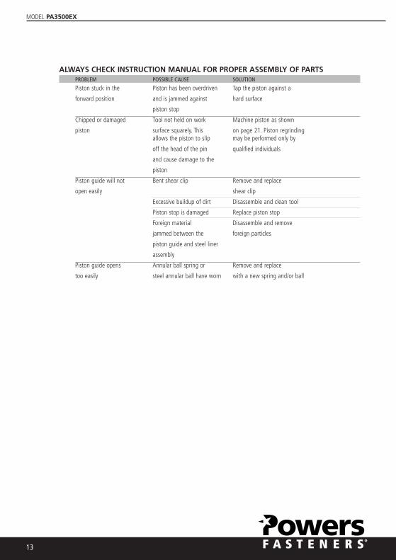
ALWAYS CHECK INSTRUCTION MANUAL FOR PROPER ASSEMBLY OF PARTSPROBLEM POSSIBLE CAUSE SOLUTION
Piston stuck in the Piston has been overdriven Tap the piston against a
forward position and is jammed against hard surface
piston stop
Chipped or damaged Tool not held on work Machine piston as shown
piston surface squarely. This on page 21. Piston regrinding allows the piston to slip may be performed only by
off the head of the pin qualified individuals
and cause damage to the
piston
Piston guide will not Bent shear clip Remove and replace
open easily shear clip
Excessive buildup of dirt Disassemble and clean tool
Piston stop is damaged Replace piston stop
Foreign material Disassemble and remove
jammed between the foreign particles
piston guide and steel liner
assembly
Piston guide opens Annular ball spring or Remove and replace
too easily steel annular ball have worn with a new spring and/or ball

MODEL PA3500EX
PA3500EX SPARE PARTS LISTINGPART NO. NO. DESCRIPTION
52166 1 Stabilizer52110 2 Baseolate 2/513-Standard52120 3 shear clip52108 4 Guide 2/F-3-Standard52104 5* Piston Flat End W Ring -Standard52107 6 Piston Ring52161 7 Piston Guide52161 8 Regulation Pin52161 9 1/8" Steel Ball52161 10 C Clip for Piston Guide52112 11 Piston Stop52163 12 Steel Liner Assembly52153 13 Pressure Pin52168 14* Front Allen Cap Screw (2) M6x2552122 15 Steel Ball52136 16 Annular Ball Spring52140 17 Ball52140 18 Spring52174 19* Housing / Adjuster Kit (Plastic)52165 20 Decorative Bullet Head52165 21 Regulation Knob52165 22 Snap Spring52165 23 Snap for Knob Head52165 24 Knob Fixer52165 25 Fixing Pin for Knob52165 26 Fixing Pin for Knob Fixer52129 27 Threaded Pin
PART NO. NO. DESCRIPTION
52146 28 Sear52134 29 Sear Spring52178 30 Spring Guide52148 31** Firing Pin52148 32** Spring Detent52148 33** Firing Pin Return Spring52148 34** Firing Pin Nut52172 35 Retaining Ring52125 36 Advance Lever Kit52125 37 Advance Lever Spring52125 38 TriggerS2125 39 Advance Lever Bushing52125 40 Advance Lever Guide52144 41 Firing Pin Spring Kit52144 42 Firing Pin Spring (Right Hand)52150 43 End Cap52156 44# Release Lever Pin52158 45# Front Cap Screw (2)52156 46# Release Lever52156 47# Trigger Return Spring52156 48# Compression Spring52156 49# Support Strip Assembly52156 50# Handle Allen Screw52156 51# Rubber Grip
* New PA3500EX Part** Firing Pin Assembly Includes Item Nos. 31-34
# Handle Assembly includes item Nos. 44-51

MODEL PA3500EX
15
PROPER MAINTENANCE AND CLEANINGMake sure the tool is not loaded. Be sure the tool is not hot prior to attempting disassembly or cleaning.
DAILY FUNCTION TESTCheck the functioning of the tool, without a powder load or fastener in the tool, by pushing down against the worksurface, pulling the trigger, and releasing the tool from the work surface. Function the unloaded tool several times andinsure that the breech parts and firing mechanism operate freely before fastening with the tool.
Your Powers Fasteners Authorized representative should be asked to assist the first time you disassemble and cleanyour tool. If you ever have any trouble reassembling the tool, or have any doubt about worn parts, call your PowersFasteners Authorized Powder Distributor.
CLEANINGAIl parts should be cleaned with detergent oil and the wire brushes supplied with your tool kit. Remove heavy dirtbuildup with the brush. After cleaning with oil, all parts should be wiped thoroughly dry. Excess oil will tend to collectdirt and dust.Wear eye protection when cleaning the tool.
The piston rod, barrel assembly, and receiver should all be cleaned of excess dirt on a daily basis. Check the conditionof the piston for damage from wear and deformation.
To maintain this tool in good working condition, it is necessary to disassemble and clean the entire tool if dirt isevident in the breech face, or if the tool appears to lose power. All parts should be cleaned with oil and wire brushes.Remove heavy dirt. All parts should be wiped thoroughly dry after cleaning with oil.
General tool maintenance should be performed at six month intervals or more frequently as required by the frequencyof tool use.
REPLACING OR REPAIRING THE PISTON & GUIDEThe piston is an expendable part and must be replaced periodically. Typical signs of a worn outpiston are: breaking, bending or mushrooming.
Prior to servicing the tool make sure there is no powder load in the tool. Use caution and do notlose or damage any tool parts.
1. Using a pin, lift the end of the annular ball spring and rotate toward the top of the tool body.Pull the piston stop back and out of the tool.
2. Slide the piston guide and baseplate assembly out of the tool.
3. Using a fastener, pry the shear clip off the baseplate.
Replace the shear clip if it is damaged.
4. Remove the baseplate from the piston guide, then pull the piston out of the guide.
REASSEMBLY:5. Tilt the baseplate and slide the fastener guide out. Press the guide out of the baseplate using apiston if it does not slide out freely. Replace the guide if it is damaged.
6. Clean the piston using a wire brush. Inspect it for worn or damaged piston ring, chipped end,or bending. Apply lubricant to the piston shank to minimize piston sticking from an overdrivecondition.
Wipe the piston dry.
7. If a piston tip is damaged, it can be shortened a maximum of 5mm. The tip of the pistonshould be ground flat and at 90 degrees to the shank of the piston. The chamfer of the pistonmust also be reground as shown. Piston grinding should be performed by qualified personnelusing the proper equipment.
8. Press the piston into the end of the piston guide. Be sure to push it all the way back into theguide. Ensure piston is positioned correctly in piston guide.
- 16
56
51
56
1-- PA 3500EXPA 3500EXPA 3500EXPA 3500EXPA 3500EX
2
1
3
4
5
6
7
8

MODEL PA3500EX
16
9. Insert the fastener guide into the baseplate.
10. Align the groove in both the piston guide and baseplate. Slide the baseplate (with fastenerguide)
onto the piston guide. Press the shear clip into place.
Insert the piston guide and baseplate assembly into the liner in the tool body. Be sure to alignthe groove with the opening for the piston stop.
11. Replace the piston stop and rotate the annular spring into place.
Upon reassembly of the tool perform the following test.
Depress the tool against a flat, hard surface and pull the trigger. The barrel assembly should slidesmoothly inside the tool housing assembly. The firing pin should release after the trigger hasbeen pulled.
CAUTION:This test should be performed without a pin or powder load in the tool.
9
10
11
POWERS FASTENERS PTY. LTD.WARRANTYMODEL PA3500EX Low Velocity Powder Actuated Fastening Tool
Powers Fasteners Pty Ltd guarantees this product in accordance with the Australian Consumer Law.Powers Fasteners Pty Ltd also warrants to the original first purchaser of this product (“you”) from a retailer that this product will be free of defects in materials and workmanship for a period of 60 months from the date of purchase; provided the product is not used or installed other than for the purpose, or in a manner not within the scope of the recommendations and limitations, specified by Powers Fasteners Pty Ltd, is new and not damaged at the time of purchase, has been maintained in accordance with the recommendations specified by Powers Fasteners Pty Ltd, has not been subjected to abuse, misuse, neglect or damage, has not been modified or repaired without the approval of Powers Fasteners Pty Ltd (“Warranty”). If you wish to claim on the Warranty, you must, at your own expense, return the product or that part of the product which you believe is defective in materials and workmanship, and provide proof of original purchase, your name, address and telephone number to Powers Fasteners Pty Ltd at the address below within 60 months from the date of purchase. Powers Fasteners Pty Ltd will assess any claim you may make on the Warranty in the above manner and if, in Powers Fasteners Pty Ltd reasonable opinion, the Warranty applies Powers Fasteners Pty Ltd will at its own option and expense replace the product (or part of the product) with the same or similar product (or part of the product) or repair the product (or part of the product) and return it to you or refund the price you paid for the product. Powers Fasteners Pty Ltd will bear its own expenses of doing those things, and you must bear any other expenses of claiming on the Warranty.The Warranty is in addition to other rights and remedies you may have under a law in relation to the product to which the Warranty relates.Our goods come with guarantees that cannot be excluded under the Australian Consumer Law. You are entitled to a replace-ment or refund for a major failure and for compensation for any other reasonably foreseeable loss or damage. You are also entitled to have the goods repaired or replaced if the goods fail to be of acceptable quality and the failure does not amount to a major failure.Powers Fasteners Pty Ltd, ABN: 41 212 423 119, Powers Fasteners Pty Ltd gives the Warranty.Powers Fasteners Pty Ltd), telephone number, address and email address are:Telephone Number: (03) 8795 4600Address: Factory 3, 205 Abbotts Road, Dandenong South, Victoria, Australia, 3175Email: [email protected]
SOUTH AUSTRALIAP: 08-8161 3000 F: 08-8443 6565
WESTERN AUSTRALIAP: 08-9408 9600 F: 08-9303 4477
NEW ZEALANDP: (64) 9 415 2425 F: (64) 9 415 2627
NORTHERN TERRITORYP: 0439 083 930
VICTORIA HEAD OFFICEFactory 3 / 205 Abbots Road,Dandenong South VIC 3175P: (61) 3 8795 4600 F: (61) 3 8787 5899
NEW SOUTH WALESP: 02-4634 7600 F: 02-4648 3139
QUEENSLANDP: 07-3712 2600 F: 07-3216 7216
FAR NORTH QUEENSLANDP: O439 083 646 F: 07-4036 1374
www.powers.com.au