operating instruction oi/266/lowp-en rev.a 2600t … · 2600t series pressure transmitters 266hsh...
TRANSCRIPT

2600T Series Pressure Transmitters 266HSH ModelLow Power Consumption (1... 5 V DC)
Operating Instruction OI/266/LowP-EN Rev.A
Engineered solutions for allapplications
Measurement Made Easy

2 OI/266/LowP-EN Rev.A | 2600T Series Pressure transmitters
The CompanyWe are an established world force in the design and manufacture of measurement products for industrial process control, flow measurement, gas and liquid analysis and environmental applications.
As a part of ABB, a world leader in process automation technology, we offer customers application expertise, service and support worldwide.
We are committed to teamwork, high quality manufacturing, advanced technology and unrivalled service and support.
The quality, accuracy and performance of the Company’s products result from over 100 year experience, combined with a continuous program of innovative design and development to incorporate the latest technology.
2600T Series Pressure transmitters | OI/266/LowP-EN Rev.A 3
Contents
Index
1 Introduction .......................................................... 4 1.1 Instruction manual structure ......................................... 4
1.2 Models covered by this manual ..................................... 4
1.3 Product description ...................................................... 4
2 Safety .................................................................... 5 2.1 General safety information ............................................ 5
2.2 Improper use ................................................................ 5
2.3 Technical limit values .................................................... 5
2.4 Warranty prevision ........................................................ 5
2.5 Use of instruction ......................................................... 5
2.6 Operator liability ........................................................... 6
2.7 Qualified personnel ....................................................... 6
2.8 Returning devices......................................................... 6
2.9 Disposal ....................................................................... 6
2.10 Information on WEEE Directive 2002/96/EC ................ 6
2.11 Transport and storage ................................................ 6
2.12 Safety information for electrical installation .................. 6
2.13 Safety information for inspection and maintenance ...... 6
3 Transmitter overview ............................................. 7 3.1 Transmitter components overview ................................. 7
3.2 Range & Span consideration ......................................... 8
4 Opening the box ................................................... 9 4.1 Identification ................................................................. 9
4.2 Optional wired-on SST plate (I1) .................................... 9
4.3 Handling ...................................................................... 9
4.4 Storage ........................................................................ 9
5 Mounting ............................................................. 10 5.1 General ...................................................................... 10
5.2 IP protection & designation ......................................... 10
5.3 Mounting the transmitter............................................. 10
5.3.1 Transmitter factory configuration consideration .... 10
5.3.2 Hazardous area considerations ........................... 10
5.4 Pressure Equipment Directive (PED) (97/23/CE)........... 10
5.4.1 Devices with PS >200 ......................................... 10
5.4.2 Devices with PS ≤200 bar ................................... 10
5.5 Mounting a P style pressure transmitter ...................... 11
5.5.1 B1 and B2 Barrel housing bracket details ............ 13
5.6 Transmitter housing rotation........................................ 13
5.7 Impulse piping connection for standard instruments .... 13
6 Transmitter wiring ............................................... 14 6.1 Cable connection ....................................................... 14
6.2 Analogue output (HART) transmitter wiring .................. 14
6.3 Supply requirement .................................................... 15
6.4 Wiring procedure ........................................................ 15
6.5 Grounding .................................................................. 16
6.6 Surge protector equipped terminal block (optional) ...... 16
6.7 Common mode voltages ............................................ 16
7 Commissioning ................................................... 17 7.1 Analague and HART Communication models .............. 17
7.2 Standard setting for error detection (alarm).................. 17
7.3 Write Protection ......................................................... 17
7.3.1 Write protection activation via dip switch.............. 17
7.4 Securing the housing cover in flameproof areas ...... 17
8 Operation ............................................................ 18 8.1 Factory settings ........................................................ 18
8.2 Configuration types .................................................... 18
8.3 Configuring the transmitter with LCD keys ................... 18
8.4 LRV and URV configuration (1 ... 5 V ranging) ............. 18
8.5 Activation procedure for the integrated LCD ................ 19
8.6 HMI as feedback of the local push button operations .. 19
8.7 HMI menu structure .................................................... 19
8.7.1 Easy Set-up ........................................................ 20
8.8 Hardware settings: dip-switch functionality .................. 21
8.9 Damping .................................................................... 21
8.10 Transfer function ....................................................... 21
8.10.1 Linear ............................................................... 21
8.10.2 Custom linearization curve ................................. 22
8.10.3 Cylindrical lying tank ......................................... 22
8.10.4 Spherical Tank ................................................. 22
8.11 Configuration with the PC or HHT ............................ 22
9 Error messages ................................................... 23 9.1 LCD Display ............................................................... 23
9.2 Error states and alarms .............................................. 23
10 Maintenance ..................................................... 25 10.1 Returns and removal ................................................ 25
10.2 Pressure transmitter sensor ...................................... 25
10.3 Pressure transducer replacement .............................. 25
10.4 Electronic replacement ............................................. 25
11 Hazardous area consideration .......................... 26 11.1 Ex Safety aspects and IP Protection (North America) . 26
11.1.1 Applicable standards ......................................... 26
11.1.2 Classifications ................................................... 26
Trouble Sheet ......................................................... 27
Return Report ........................................................ 28

4 OI/266/LowP-EN Rev.A | 2600T Series Pressure transmitters
1 Introduction
1 Introduction
1.1 Instruction manual structureThe present manual provides information on installing, operating, troubleshooting the 266 pressure transmitter. Every section of the present manual is specifically dedicated to the specific phase of the transmitter lifecycle starting from the receipt of the transmitter and its identification, passing to the installation, to the electrical connections, to the configuration and to the troubleshooting and maintenance operations.
1.2 Models covered by this manualThe present manual can be used for 266HSH Low Power consumption pressure transmitter.
1.3 Product descriptionThe pressure transmitters model 266 is microprocessor-based, electronic field device. Accurate and reliable measurement of gauge pressure is provided even in the most difficult and hazardous industrial environments.

2600T Series Pressure transmitters | OI/266/LowP-EN Rev.A 5
2 Safety notes
2 Safety
2.1 General safety informationThe “Safety” section provides an overview of the safety aspects to be observed for operation of the device.
The device has been constructed in accordance with the state of the art and is operationally safe. It has been tested and left the factory in perfect working conditions. The information in the manual, as well as the applicable documentation and certificates, must be observed and followed in order to maintain this condition throughout the period of operation.
Full compliance with the general safety requirements must be observed during operation of the device. In addition to the general information, the individual sections in the manual contain descriptions of processes or procedural instructions with specific safety information.
Only by observing all of the safety information can you reduce to the minimum the risk of hazards for personnel and/or environment. These instructions are intended as an overview and do not contain detailed information on all available models or every conceivable event that may occur during setup, operation, and maintenance work.
For additional information, or in the event of specific problems not covered in detail by these operating instructions, please contact the manufacturer. In addition, ABB declares that the contents of this manual are not part of any prior or existing agreements, commitments, or legal relationships; nor are they intended to amend these.
All obligations of ABB arise from the conditions of the relevant sales agreement, which also contains the solely binding warranty regulations in full. These contractual warranty provisions are neither extended nor limited by the information provided in this manual.
Caution. Only qualified and authorized specialist personnel should be charged with installation, electrical connection, commissioning, and maintenance of the transmitter. Qualified personnel are persons who have experience in installation, electrical wiring connection, commissioning, and operation of the transmitter or similar devices, and hold the necessary qualifications such as:
— Training or instruction, i.e., authorization to operate and maintain devices or systems according to safety engineering standards for electrical circuits, high pressures, and aggressive media
— Training or instruction in accordance with safety engineering standards regarding maintenance and use of adequate safety systems.
For safety reasons, ABB draws your attention to the fact that only sufficiently insulated tools conforming to DIN EN 60900 may be used.
Since the transmitter may form part of a safety chain, we recommend replacing the device immediately if any defects are detected. In case of use in Hazardous Area non sparking tools only must be employed.
In addition, you must observe the relevant safety regulations regarding the installation and operation of electrical systems, and the relevant standards, regulations and guidelines about explosion protection.
Warning. The device can be operated at high levels of pressure and with aggressive media. As a result, serious injury or significant property damage may occur if this device is operated incorrectly.
2.2 Improper useIt is prohibited to use the device for the following purposes:
— As a climbing aid, e.g., for mounting purposes
— As a support for external loads, e.g., as a support for pipes.
— Adding material, e.g., by painting over the name plate or welding/soldering on parts
— Removing material, e.g., by drilling the housing.
Repairs, alterations, and enhancements, or the installation of replacement parts, are only permissible as far as these are described in the manual. Approval by ABB must be requested for any activities beyond this scope. Repairs performed by ABB-authorized centers are excluded from this.
2.3 Technical limit valuesThe device is designed for use exclusively within the values stated on the name plates and within the technical limit values specified on the data sheets.
The following technical limit values must be observed:
— The Maximum Working Pressure may not be exceeded.
— The Maximum ambient operating temperature may not be exceeded.
— The Maximum process temperature may not be exceeded.
— The housing protection type must be observed.
2.4 Warranty previsionUsing the device in a manner that does not fall within the scope of its intended use, disregarding this manual, using underqualified personnel, or making unauthorized alterations, releases the manufacturer from any liability for any resulting damage. This makes the manufacturer’s warranty null and void.
2.5 Use of instruction
Danger – <Serious damage to health/risk to life>. This message indicates that an imminent risk is present. Failure to avoid this will result in death or serious injury.
Caution – <Minor injuries>. This message indicates a potentially dangerous situation. Failure to avoid this could result in minor injuries. This may also be used for property damage warnings.
Important. This message indicates operator tips or particularly useful information. It does not indicate a dangerous or damaging situation.

6 OI/266/LowP-EN Rev.A | 2600T Series Pressure transmitters
2 Safety notes
Warning – <Bodily injury>. This message indicates a potentially dangerous situation. Failure to avoid this could result in death or serious injury
Attention – <Property damage>. This message indicates a potentially damaging situation. Failure to avoid this could result in damage to the product or its surrounding area.
2.6 Operator liabilityPrior to using corrosive and abrasive materials for measurement purposes, the operator must check the level of resistance of all parts coming into contact with the materials to be measured.
ABB will gladly support you in selecting the materials, but cannot accept any liability in doing so.
The operators must strictly observe the applicable national regulations with regard to installation, function tests, repairs, and maintenance of electrical devices.
2.7 Qualified personnelInstallation, commissioning, and maintenance of the device may only be performed by trained specialist personnel who have been authorized by the plant operator. The specialist personnel must have read and understood the manual and comply with its instructions.
2.8 Returning devicesUse the original packaging or suitably secure shipping package if you need to return the device for repair or recalibration purposes. Fill out the return form (see the end of the document) and include this with the device.
According to EC guidelines and other local laws for hazardous materials, the owner of hazardous waste is responsible for its disposal. The owner must observe the proper regulations for shipping purposes.
All devices sent back to ABB must be free from any hazardous materials (acids, alkalis, solvents, etc.).
2.9 DisposalABB actively promotes environmental awareness and has an operational management system that meets the requirements of EN ISO 9001:2008 and EN ISO 14001:2008. Our products and solutions are intended to have minimum impact on the environment and persons during manufacturing, storage, transport, use and disposal.
This includes the environmentally friendly use of natural resources. ABB conducts an open dialog with the public through its publications.
This product/solution is manufactured from materials that can be reused by specialist recycling companies.
2.10 Information on WEEE Directive 2002/96/EC (Waste Electrical and Electronic Equipment)This product or solution is not subject to the WEEE Directive 2002/96/EC or corresponding national laws (e.g., the ElektroG - Electrical and Electronic Equipment Act - in Germany). Dispose of the product/solution directly at a specialist recycling facility; do not use municipal garbage collection points for this purpose.
According to the WEEE Directive 2002/96/EC, only products used in private applications may be disposed of at municipal garbage facilities. Proper disposal prevents negative effects on people and the environment, and supports the reuse of valuable raw materials. ABB can accept and dispose of returns for a fee.
2.11 Transport and storage— After unpacking the pressure transmitter, check the device for transport damage.
— Check the packaging material for accessories.
— During intermediate storage or transport, store the pressure transmitter in the original packaging only.
For information on permissible ambient conditions for storage and transport, see “Technical data”. Although there is no limit on the duration of storage, the warranty conditions stipulated on the order acknowledgment from the supplier still apply.
2.12 Safety information for electrical installationElectrical connections may only be established by authorized specialist personnel in accordance with the electrical circuit diagrams. The electrical connection information in the manual must be observed; otherwise, the applicable protection type may be affected. Ground the measurement system according to requirements.
2.13 Safety information for inspection and maintenance
Warning – Risk to persons. There is no EMC protection or protection against accidental contact when the housing cover is open. There are electric circuits within the housing which are dangerous if touched. Therefore, the auxiliary power must be switched off before opening the housing cover.
Warning – Risk to persons. The device can be operated at high pressure and with aggressive media. Any process media released may cause severe injuries. Depressurize the pipeline/tank before opening the transmitter connection.
Corrective maintenance work may only be performed by trained personnel.
— Before removing the device, depressurize it and any adjacent lines or containers.
— Check whether hazardous materials have been used as materials to be measured before opening the device. Residual amounts of hazardous substances may still be present in the device and could escape when the device is opened.
— Within the scope of operator responsibility, check the following as part of a regular inspection:
Pressure-bearing walls/lining of the pressure device
Measurement-related function
Leak-tightness
Wear (corrosion)

2600T Series Pressure transmitters | OI/266/LowP-EN Rev.A 7
3 Transmitter overview
3 Transmitter overview
3.1 Transmitter components overview
Figure 1: Gauge pressure transmitter components

8 OI/266/LowP-EN Rev.A | 2600T Series Pressure transmitters
3 Transmitter overview
3.2 Range & Span considerationThe 2600T Transmitter Specification Sheets provide all information concerning the Range and Span limits in relation to the model and the sensor code.
The terminology currently used to define the various parameters is as follows:
URL: Upper Range Limit of a specific sensor. The highest value of the measured value that the transmitter can be adjusted to measure.
LRL: Lower Range Limit of a specific sensor. The lowest value of the measured value that the transmitter can be adjusted to measure.
URV: Upper Range Value. The highest value of the measured value to which the transmitter is calibrated.
LRV: Lower Range Value. The lowest value of the measured value to which the transmitter is calibrated.
SPAN: The algebraic difference between the Upper and Lower Range Values. The minimum span is the minimum value that can be used without degradation of the specified performance.
TD: (or Turn Down Ratio) is the ratio between the maximum span and the calibrated span.
The transmitter can be calibrated with any range between the LRL and the URL with the following limitations:
LRL ≤ LRV ≤ (URL - CAL SPAN)
CAL SPAN ≥ MIN SPAN
URV ≤ URL

2600T Series Pressure transmitters | OI/266/LowP-EN Rev.A 9
4 Opening the box
Figure 2: Product identification
Local keys below label
PRODUCT CODESEAL-H SEAL-LSPEC.REQUEST
LRL/URLSPAN LIMITS
POWER SUPPLY OUTPUT SIGNAL
ABB S.p.A. Made in Italy
TS PS
SERIAL\NUMBER
SENSOR DIAPH.-FILLFLANGE/CONN.-GASKET/S
H DIAPH.-FILLL DIAPH.-FILLSE
AL
HW Rev. MD:
PED:
MWP/OVP
General Purpose IP66/67 ENCL Type 4X Max.Supply Voltage 30 Vdc
XP (US) CL I/DIV1/GP ABCD, DIP CL II, III /DIV1/GP EFG,XP (Canada) CL I/DIV1/GP BCD, DIP CL II, III /DIV1/GP EFG,CL I, ZONE 1, AEx/Ex d IIC T4 -50°C<Ta<+85°C ENCL Type 4X T AMB=85°C "Seal not required"
APPROVED
FMC US
ABB S.p.A.Lenno (Co) Italy
A
B
C
2600T Tag Number
Calib.Range
PRESSURE TRANSMITTER
4 Opening the box
4.1 IdentificationThe instrument is identified by the data plates shown in Figure 3. The certification plate (ref. A): contains the certification related parameters for use in Hazardous area.
The Nameplate (ref.B), always made of AISI 316 ss, provides information concerning the model code, maximum working pressure, range and span limits, power supply, output signal, diaphragms material, fill fluid, range limit, serial number, maximum process working pressure (PS) and temperature (TS).
The Tag plate, instead, provides customer tag number and calibrated range.
Both certification and tag plates are supplied self-adhesive attached to the electronics housing, as standard. Option I2 allows to select these plates as metal AISI 316 ss fastened to the electronics housing with rivets or screws
The instrument may be used as a pressure accessory (category III) as defined by the Pressure Equipment Directive 97/23/EC. In this case, near the CE mark, you will find the number of the notified body (0474) that have verified the compliance. 266 pressure transmitters are in compliance with EMC Directive 2004/108/CE.
4.2 Optional wired-on SST plate (I1)The 266 transmitter can be supplied with the optional “Wired-On Stainless Steel plate” (figure 4) which is permanently laser printed with a custom text specified in phase of order. The available space consists in 4 lines with 32 characters per line.
The plate will be connected to the transmitter with a Stainless Steel wire.
AAAAAAAAAAAAAAAAAAAAAAAAAAAAAAAABBBBBBBBBBBBBBBBBBBBBBBBBBBBBBBBCCCCCCCCCCCCCCCCCCCCCCCCCCCCCCCCDDDDDDDDDDDDDDDDDDDDDDDDDDDDDDDD
Figure 3: 4-line layout of the optional wired-on Stainless Steel plate
4.3 HandlingThe instrument does not require any special precautions during handling although normal good practice should be observed.
4.4 StorageThe instrument does not require any special treatment if stored as dispatched and within the specified ambient conditions. There is no limit to the storage period, although the terms of guarantee remain as agreed with the Company and as given in the order acknowledgement.
Model 266HSH Storage temperature limits
With LCD –40 and 85 °C (–40 and 185 °F)

10 OI/266/LowP-EN Rev.A | 2600T Series Pressure transmitters
5 Mounting
5 Mounting
5.1 GeneralStudy these installation instructions carefully before proceeding. Failure to observe the warnings and instructions may cause a malfunction or personal hazard. Before installing the transmitter, check whether the device design meets the requirements of the measuring point from a measurement technology and safety point of view.
This applies in respect of the:
— Explosion protection certification
— Measuring range
— Gauge pressure stability
— Temperature
— Operating voltage
The suitability of the materials must be checked as regards their resistance to the media. This applies in respect of the:
— Gasket
— Process connection, isolating diaphragm, etc.
In addition, the relevant directives, regulations, standards, and accident prevention regulations must be observed (e.g., VDE/VDI 3512, DIN 19210, VBG, Elex V, etc.). Measurement accuracy is largely dependent on correct installation of the pressure transmitter and, if applicable, the associated measuring pipe(s). As far as possible, the measuring setup should be free from critical ambient conditions such as large variations in temperature, vibrations, or shocks.
Important. If unfavorable ambient conditions cannot be avoided for reasons relating to building structure, measurement technology, or other issues, the measurement quality may be affected. If a remote seal with capillary tube is installed on the transmitter, the additional operating instructions for remote seals and the related data sheets must be observed.
5.2 IP protection & designationThe housings for 266 transmitters are certified as conforming to protection type IP66 / IP67 (according to IEC 60529) or NEMA Type 4X (according to NEMA 250).
The first number indicates the type of protection the integrated electronics have against the entry of foreign bodies, including dust.
“6” means that the housing is dust-proof (i.e., no ingress of dust). The second number indicates the type of protection the integrated electronics have against the entry of water.
The second number indicates the type of protection the integrated electronics have against the entry of foreign bodies, including water.
“6” means that the housing is protected against water; specifically, powerful jets of water under standardized conditions.
“7” means that the housing is protected against water; specifically, against the effects of temporary immersion in water under standardized water pressure and temporal conditions.
5.3 Mounting the transmitter5.3.1 Transmitter factory configuration consideration The 266 pressure transmitter in your hands has been factory calibrated to reflect the published declared performance specification; no further calibration is required in normal condition. ABB typically configures 266 pressure transmitters according to the user requirements. A typical configuration includes:
— TAG number
— Calibrated span
— Output linearization
— LCD display configuration
5.3.2 Hazardous area considerations The transmitter must be installed in hazardous area only if it is properly certified. The certification plate is permanently fixed on the neck of the transmitter top housing. The 266 Pressure Transmitter Line can have the following certifications:
FM Approvals US and FM Approvals Canada (option code EB):
— Explosionproof (US): Class I, Div. 1, Groups A, B, C, D
Class I, Zone 1 AEx d IIC T4
— Explosionproof (Canada): Class I, Div. 1, Groups B, C, D
Class I, Zone 1 Ex d IIC T4
— Dust Ignitionproof: Class II, Div. 1, Groups E, F, G
Warning – General Risk for model 266 used in zone 0. Model 266 enclosure contains aluminum and is considered to present a potential risk of ignition by impact or friction. Care must be taken into account during installation and use to prevent impact or friction.
Figure 4: 266 nameplate with PED data
Local keys below label
PRODUCT CODESEAL-H SEAL-LSPEC.REQUEST
LRL/URLSPAN LIMITS
POWER SUPPLY OUTPUT SIGNAL
ABB S.p.A. Made in Italy
TS PS
SERIAL\NUMBER
SENSOR DIAPH.-FILLFLANGE/CONN.-GASKET/S
H DIAPH.-FILLL DIAPH.-FILLSE
AL
HW Rev. MD:
PED:
MWP/OVP
5.4.2 Devices with PS ≤200 barDevices with a permissible pressure PS ≤200 bar correspond to article 3 paragraph (3). They have not been subject to a conformity validation. These instruments were designed and manufactured acc. to SEP Sound Engineering Practices.
5.4 Pressure Equipment Directive (PED) (97/23/CE)5.4.1 Devices with PS >200Devices with a permissible pressure PS >200 bar have been subject to a conformity validation. The data label includes the following specifications:

2600T Series Pressure transmitters | OI/266/LowP-EN Rev.A 11
5 Mounting
5.5 Mounting a P style pressure transmitterThe pressure transmitter can be mounted directly on the manifold.
A mounting bracket for wall or pipe mounting (2” pipe) is also available as an accessory.
Ideally, the pressure transmitter should be mounted in a vertical position to prevent subsequent zero shifts.
Figure 5 Model 266HSH with 1/2-14 NPT male process connection and barrel housing installed on a 2”pipe with optional bracket (B6 carbon steel or B7 Stainless Steel 316L) for sensor P, Q and S
Important. If the transmitter is installed inclined with respect to the vertical, the filling liquid exerts hydrostatic pressure on the measuring diaphragm, resulting in a zero shift. In such an event, the zero point can be corrected via the “set PV to zero” command. Please refer to the configuration section for further details. Vent / Drain considerations below should also be taken into consideration.
91 (3.58)
72 (2.83)
18 (0.71)
113 (4.45) 29 (1.14)
18 (0.71)
145
(5.7
1)
91 (3.58)
18 (0
.71)
16 (0
.63)
108 (4.25)
72 (2.83)
39 (1
.54)
49 (1.93)
54 (2
.13)
1/2 - 14 NPT
32 (1.26) width acrossflats of exagon
Figure 6: Model 266HSH with 1/2-14 NPT female process connection and barrel housing installed on a 2”pipe with optional bracket (B6 carbon steel or B7 Stainless Steel 316L) for sensor P, Q and S
18 (0.71)
113 (4.45)
18 (0.71)
145
(5.7
1)18
(0.7
1)
16 (0
.63)
108 (4.25) 49 (1.93)
39 (1
.54)
32 (1.26) width acrossflats of exagon
54 (2
.13)
18 (0.71) 113 (4.45) 18 (0.71)14
5 (5
.71)
18 (0
.71)
16 (0
.63)
36 (1
.42)
108 (4.25) 49 (1.93)
19 (0
.75)
32 (1.26) width acrossflats of exagon

12 OI/266/LowP-EN Rev.A | 2600T Series Pressure transmitters
5 Mounting
36 (1.42) width across flats
18 (0.71) 113 (4.45) 18 (0.71)
145
(5.7
1)
91 (3.58)
18 (0
.71)
16 (0
.63)
108 (4.25)72 (2.83)
65 (2.56)
40 (1
.58)
72 (2
.83)
18 (0.71) 113 (4.45) 18 (0.71)
145
(5.7
1)18
(0.7
1)
16 (0
.63)
108 (4.25)
52 (2
.05)
27 (1.06) width across flats
Figure 7: Model 266HSH with 1/2-14 NPT male process connection and barrel housing installed on a 2”pipe with optional bracket (B6 carbon steel or B7 Stainless Steel 316L) for sensor W
Figure 8: Model 266HSH with 1/2-14 NPT female process connection and barrel housing installed on a 2”pipe with optional bracket (B6 carbon steel or B7 Stainless Steel 316L) for sensor W
91 (3.58)
72 (2.83)

2600T Series Pressure transmitters | OI/266/LowP-EN Rev.A 13
5 Mounting
5.5.1 B1 and B2 Barrel housing bracket details
Figure 9: Pipe and wall mounting bracket kits for P style transmitter with Barrel housing
1 – U-bolt
2 – U-bolt fixing washers and nuts
3 – Transmitter fixing bolts
4 – B1 or B2 bracket
5 – Fitting adapter (supplied with 266HSH)
1
2
3
4
5
5.6 Transmitter housing rotationTo improve field access to the wiring or the visibility of the optional LCD meter, the transmitter housing may be rotated through 360° and fixed in any position. A stop prevents the housing from being turned too far. In order to proceed with housing rotation, the housing stop tang-screw has to be unscrewed by approximately 1 rotation (do not pull it out) and, once the desired position has been reached, retightened.
5.7 Impulse piping connection for standard instrumentsIn order for the pipes to be laid correctly, the following points must be observed:
— The measuring pipes must be as short as possible and free from sharp bends.
— Lay the impulse piping in such a way that no deposits accumulate in them. Gradients should not be less than approx. 8% (ascending or descending).
— The measuring pipes should be blown through with compressed air or, better yet, flushed through with the measuring medium before connection.
— Completely depressurize the impulse lines if the medium is a fluid.
— Lay the impulse lines in such a way that gas bubbles (when measuring fluids) or condensate (when measuring gases) can flow back into the process line.
— Ensure that the impulse lines are connected correctly
— Make sure the connection is tight.
— Lay the impulse line in such a way that prevents the medium from being blown out over the measuring equipment.
Caution. Process leaks may cause harm or result in death. Install and tighten process connectors and all accessories (including manifolds) before applying pressure. In case of toxic or otherwise dangerous process fluid, take any precautions as recommended in the relevant Material Safety Data Sheet when draining or venting. Use only a 12 mm (15/32“) hexagonal spanner to tighten the bracket bolts.

14 OI/266/LowP-EN Rev.A | 2600T Series Pressure transmitters
6 Transmitter wiring
+--
-
+++
6 Transmitter wiring
6.1 Cable connectionDepending on the design supplied, the electrical connection is established via a cable entry or 1/2-14 NPT thread. The screw terminals are suitable for wire cross sections of up to 2.5 mm2 (AWG 14).
Important. With Category 3 transmitters for use in “Zone 2”, a qualified cable gland for this type of protection must be installed by the customer (see the section “Hazardous Area Consideration”). An M20 x 1.5 threads is located in the electronics housing for this purpose. For transmitters with “Flameproof enclosure” (Ex d) type of protection, the housing cover must be secured using the locking screw. The screw plug that may have been supplied with the transmitter must be sealed at the plant using Molykote DX.
The installer assumes responsibility for any other type of sealing medium used. At this point, we wish to draw your attention to the fact that increased force will be required to unscrew the housing cover after an interval of several weeks.
This is not caused by the threads, but instead is due solely to the type of gasket.
6.2 Analogue output (HART) transmitter wiring
1 - Power source
2 - Hand-held communicator
3 - External ground termination point
4 - Internal ground termination point
5 - Line load
6 - 1 to 5 V DC out (Voltmeter)
1
2
54
3
6
HART hand-held communicator may be connected or between the terminals Vout/COMM and PWR- or at the terminal blocks of the voltmeter.
Figure 10: HART transmitter connection scheme
Warning - General risks. Observe the applicable regulations governing electrical installation. Connections must only be established in a dead-voltage state. Since the transmitter has no switch-off elements, overvoltage protection devices, lightning protection, and voltage separation capacity must be provided at the plant (overvoltage/lightning protection is optional). Check that the existing operating voltage corresponds to the voltage indicated on the name plate. The same lines are used for both the power supply and output signal. In case the surge protection option is present and the transmitter is installed in a Hazardous area, the transmitter has to be power supplied from a voltage source isolated from mains (galvanic separation). Furthermore the potential equalization for the entire powering cable must be guaranteed since the intrinsic safety circuit of the transmitter is grounded.
Electrical shock can result in death or serious injury. Avoid contact with the leads and terminals. High voltage that may be present on leads can cause electrical shock.
Do NOT make electrical connections unless the electrical code designation stamped on the transmitter data plate agrees with the classification of the area in which the transmitter is to be installed. Failure to comply with this warning can result in fire or explosion.

2600T Series Pressure transmitters | OI/266/LowP-EN Rev.A 15
6 Transmitter wiring
6.3 Supply requirementFor signal connection use, wiring no 18 to 22 AWG / 0.8 to 0.35mm2 ø up to 164 feet (50 meters). Longer loops require larger wire. For power connection use, wiring no 18 to 22 AWG / 0.8 to 0.35mm2.
The 1 to 5 V dc output signal and the dc power supply to the transmitter are separated.
The supply voltage at the transmitter terminals must be between the limits of 8 and 30 V dc.
For Ex ia approval power supply must not exceed 30 Vdc.
For maximum power supply voltage please refer to the top identification plate of the transmitter.
6.4 Wiring procedureFollow these steps to wire the transmitter:
— Remove the temporary plastic cap from one of the two electrical connection ports located at both sides in the upper part of the transmitter housing.
— These connection ports may have a 1/2 inch internal NPT or M20 threads. Various adaptors and bushings can be fitted to these threads to comply with plant wiring (conduit) standards.
— Remove the housing cover of the “field terminals” side. See the indication on the label on top of the housing. In an Explosion-Proof/Flame-Proof installation, do not remove the transmitter covers when power is applied to the unit.
— Run the cable through the cable gland and the open port.
— Connect the POWER supply, the positive lead to the PWR+ terminal, and the negative lead to the PWR– terminal.
— Connect the signal_out 1-5V, the positive lead to the Vout/COMM+ terminal and the negative lead to the PWR– terminal.
— Plug and seal the electrical ports. Make sure that when the installation has been completed, the electrical ports are properly sealed against entry of rain and/or corrosive vapors and gases.
Warning - General risks. Cable, cable gland and unused port plug must be in accordance with the intended type of protection (e.g. intrinsically safe, explosion proof, etc.) and degree of protection (e.g. IP6x according to IEC EN 60529 or NEMA 4x). See also the addendum for “EX SAFETY” ASPECTS AND “IP” PROTECTION. In particular, for explosion proof installation, remove the red temporary plastic cap and plug the unused opening with a plug certified for explosion containment
— If applicable, install wiring with a drip loop. Arrange the drip loop so the bottom is lower than the conduit connections and the transmitter housing.
— Put back the housing cover, turn it to seat O-ring into the housing and then continue to hand tighten until the cover contacts the housing metal-to-metal. In Ex-d (Explosion Proof) installation, lock the cover rotation by turning the set nut (use the 2mm Allen key supplied with the instrument).

16 OI/266/LowP-EN Rev.A | 2600T Series Pressure transmitters
6 Transmitter wiring
6.5 GroundingPressure transmitter housing should be grounded or earthed in accordance with national and local electrical codes. Ground connection is mandatory for surge protector equipped devices in order to ensure proper functioning.
Protective grounding terminals (PE) are available outside and/or inside the housing of the transmitter. Both ground terminals are electrically connected and it up to the user to decide which one to use. The most effective transmitter case grounding method is direct connection to earth ground with impedance equal or less of 5 ohm.
Figure 11: Ground connection on transmitter housing
6.6 Surge protector equipped terminal block (optional)The pressure transmitter housing with surge protector (code S2) inside the terminal board must be connected using the grounding terminal (PE), by means of a short connection with the equipotential bonding.
Equipotential bonding conductor must to have 4 mm2 of maximum cross-section.
Important. Test voltage withstand capability can no longer be ensured when this protective circuit is used.
6.7 Common mode voltages266 pressure transmitter operates within the specified levels of accuracy for common-mode voltages of up to 250V between lines and housing grounded and up to 150V not grounded.
2600T Series Pressure transmitters | OI/266/LowP-EN Rev.A 17
7 Commissioning
7.1 Analogue and HART Communication modelsIf the pressure applied falls within the values indicated on the name plate, the output current will be between 1 and 5 V. If the pressure applied falls outside the set range, the output current will be between 0.9 V and 1 V if the range is undershot or between 5 V and 5.6 V if the range is overshot (depending on the respective configuration).
7.2 Standard setting for error detection (alarm)The LCD integral display can be used to diagnose the error.
Important. A brief interruption in the power supply results in initialization of the electronics (program restarts).
Important. Alarm Current
— Lower limit: 0.94 V (configurable from 0.9 V to 1 V)
— Upper limit: 5.4 V (configurable from 5 V to 5.6 V)
Factory settings: high alarm current (5.4 V)
7 CommissioningOnce the transmitter has been installed, it is put into operation by switching on the operating voltage.
Check the following before switching on the operating voltage:
— Process connections
— Electrical connection
— The impulse line/s and the measuring chamber of the measuring equipment must be completely filled with the measuring medium.
The transmitter can then be put into operation. To do this, the shut-off valves must be actuated in the following sequence (in the default setting, all valves are closed).
Gauge model — Open the shut-off valve on the pressure tap connection
— Open the positive shut-off valve.
To put the transmitter out of operation, carry out the steps in reverse order.
Important. If, when using “intrinsically safe” transmitters, an ammeter is connected to the output circuit or a modem is connected in parallel while there is a risk of explosion, the sums of the capacitances and inductances of all circuits, including the transmitter (see EC-type-examination certificate) must be equal to or less than the permissible capacitances and inductances of the intrinsically safe signal circuit (see EC-type-examination certificate for the supply unit).
Only passive or explosion-proof devices or indicators may be connected. If the output signal stabilizes only slowly, it is likely that a large damping time constant has been set on the transmitter.
7.3 Write Protection
Write protection prevents the configuration data from being overwritten by unauthorized users.
If write protection is enabled, the buttons located in the lower part of the display are disabled and a lock icon appears. However, it is still possible to read out the configuration data using a communication tool like a handheld terminal. The control unit may be leaded if required.
7.3.1 Write protection activation via dip switchTo activate this function it is necessary to proceed as detailed below:
— Remove instrument windowed cover.
— On the connection board, place dip switch 4 in “up” position.7.2 Correcting the lower range value / zero shift
During installation of the transmitter, caused by mounting (e.g., a slightly oblique mounting position, etc.) may occur; these must be corrected.
Important. The transmitter must have reached its operating temperature (approx. 5 min. after startup, if the transmitter has already reached the ambient temperature) in order to perform zero shift correction. The correction must be made at P = 0.
7.4 Securing the housing cover in flameproof areasEach of the front faces of the electronics housing features a locking screw (hex-head socket screw) on the bottom side.
— Install the housing cover to the housing by hand- tightening it.
— Turn the locking screw counterclockwise to secure the housing cover. This involves unscrewing the screw until the screw head stops at the housing cover.

18 OI/266/LowP-EN Rev.A | 2600T Series Pressure transmitters
8 Operation
8 Operation
8.1 Factory settings Transmitters are calibrated at the factory to the customer’s specified measuring range. The calibrated range is provided on the name plate whereas the tag number on the additional tag plate. The calibrated range and tag number are provided on the name plate. If this data has not been specified, the transmitter will be delivered with the following configuration:
Parameter Factory settingLower Range Value (LRV) (1V) ZeroUpper Range Value (URV) (5V) Upper Range Limit (URL)Output transfer function LinearDamping 1 secondTransmitter failure (alarm) Upscale (5.4V)Optional LCD HMI scale 1 line PV
Important. Every configurable parameters listed here above can easily be modified with an HART handheld terminal running proper EDD file. Information regarding materials, filling liquid type, etc. is stored inside the non-volatile memory of the device.
8.2 Configuration typesPressure transmitters can be configured as follows:
— Configuration of the parameters for the lower and upper range values via LCD keys.
— Configuration with a handheld terminal
8.3 Configuring the transmitter with LCD keysThe “lower range value” and “span” parameters can be set directly on the transmitter using the LCD keys.
The transmitter has been calibrated by the manufacturer based on the order information. The tag plate contains information on the “lower range value” and “upper range value” set. In general, the following applies:
The first pressure value (e.g., 0 mbar) is always assigned to the 1V signal (or 0%), while the second pressure value (e.g., 400 mbar) is always assigned to the 5V signal (or 100%). To change the transmitter ranging apply the pressure for the “lower range value” and “upper range value” to the measuring equipment. Make sure that the measuring limits are not exceeded.
Important. Reducing station with adjustable pressure and reference displays can be used as pressure generators.
When making the connection, please ensure that there are no residual fluids (for gaseous testing materials) or air bubbles (for fluid testing materials) in the impulse lines, since these can lead to errors during inspection. Any potential measuring error for the pressure generator should be at least three times smaller than the desired measuring error for the transmitter. It is recommended that the damping is set to 1 second.
8.4 LRV and URV configuration (1 ... 5 V ranging) — Apply the lower range value for pressure (1 V) from the process or from a pressure generator. The pressure must be stable and applied with a high level of accuracy << 0.05 % (observing the set damping value).
— Remove instrument windowed cover.
— Press “Z” LCD key for two seconds to set the output signal to 1 V. Operator will be asked about proceeding with the operation in progress. By depressing “Yes” a small screwdriver icon will appear on the bottom of the LCD. A confirmation string (“Oper Done”) will be shown on device main screen on button release (for additional string messages, refer to section ”8.6 HMI as feedback of the local push button operations”). The span will remain unchanged.
— Apply the pressure for the “upper range value” and wait approx. 30 s until it has stabilized.
— Press “S” LCD key to set the output current to 5V and adjust the Span. As described above, operator will be asked about proceeding with the operation in progress. A confirmation message will be shown at the end of Span adjustment.
— Record the new settings. The respective parameter will be stored in the non-volatile memory 20 seconds after the confirmation has been given.
Figure 12: Operating with the display keypad

2600T Series Pressure transmitters | OI/266/LowP-EN Rev.A 19
8 Operation
Important. This configuration procedure only changes the 1 … 5V signal; it does not affect the physical process pressure (PV value) also shown on the digital display or user interface. After performing a correction, you must check the device configuration.
Important. Setting the lower range value by using this button is possible if the write protection is not enabled.
8.5 Activation procedure and considerations for the integrated LCDThe integral LCD HMI is integrated to the 266 communication board. It can be used to visualize the process measured variables as well as to configure the display and the transmitter.
In addition, diagnostic information is provided. To access the functionality of the HMI the following activation procedure needs to be carried out:
— Keys “Z” and “S” need to be pressed simuoltaneously for 5 seconds to initiate the configurable mode.
— Press key “S” to access the menu. Key “Z” give direct access to the diagnostics visualization.
Figure 13: Display keypad
— The menu / submenu name is displayed above in the LCD display.
— The number / line of the currently selected menu item is displayed in the upper right of the LCD display.
— A scroll bar is located on the right edge of the LCD display which shows the relative position of the currently selected menu item within the menu.
— Both of the keys can have various functions. The meaning of these buttons is displayed below in the LCD display above the respective button.
Button (1) functionalities MeaningExit Exit menuBack Back one submenu
CancelExit without saving the selected parameter
value
NextSelect next position for entering numerical
values or letters
Button (4) functionalities MeaningSelect Select submenu/parameter
Edit Edit parameter
OkSave selected parameter and display
stored parameter value
8.6 HMI as feedback of the local push button operationsAs consequence of the operations described in the section 8.2, when the Z or S buttons are released, the feedback of the executed operation is displayed in the bottom of the LCD (same position as per diagnostic messages):
Message Description
! Oper Done The push button operation has been successfully executed
! Proc Too
Low
The Pressure measured in input is too low and not
acceptable for the requested operation
! Proc Too
High
The Pressure measured in input is too high and not
acceptable for the requested operation
! New URV
Error
The Zero (Z) operation cannot be accepted because the
URV would be shifted outside the Upper Sensor limit
! Span Error
The Span (S) operation cannot be accepted because the
new URV would be too close to the LRV and their
difference lower than the Minimum Span value
! Oper
Disabled
The push button operation has been refused because the
Write Protection is enabled.
! LRV Too
Low
New LRV is too low and not acceptable for the requested
operation
LRV Too
High
New LRV is too high low and not acceptable for the
requested operation
URV Too
Low
New URV is too low and not acceptable for the requested
operation
URV Too
High
New URV is too high and not acceptable for the requested
operation
8.7 HMI menu structureFollow the instruction on the screen to perform the configuration of the different parameters.
Integrated LCD display allows the verification and the parameterization of the basic configuration of the 266 pressure transmitter. The menu driven structure will guide you to the choice of the interface language, the engineering units, the LRV and URV (Lower range value and Upper range value), the transfer function, the damping time and the display line 1 visualization mode (the value that need to be visualized on the LCD).
20 OI/266/LowP-EN Rev.A | 2600T Series Pressure transmitters
8 Operation
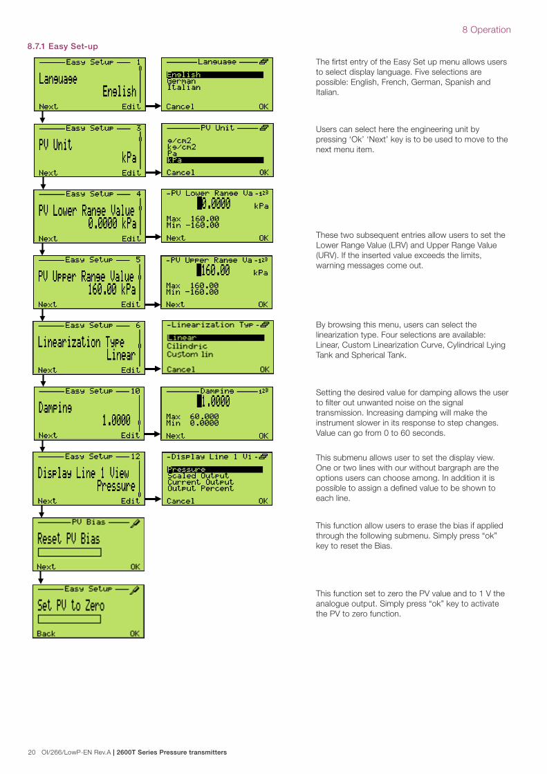
8.7.1 Easy Set-up
The firtst entry of the Easy Set up menu allows users to select display language. Five selections are possible: English, French, German, Spanish and Italian.
Users can select here the engineering unit by pressing ‘Ok’ ‘Next’ key is to be used to move to the next menu item.
These two subsequent entries allow users to set the Lower Range Value (LRV) and Upper Range Value (URV). If the inserted value exceeds the limits, warning messages come out.
By browsing this menu, users can select the linearization type. Four selections are available: Linear, Custom Linearization Curve, Cylindrical Lying Tank and Spherical Tank.
This submenu allows user to set the display view. One or two lines with our without bargraph are the options users can choose among. In addition it is possible to assign a defined value to be shown to each line.
Setting the desired value for damping allows the user to filter out unwanted noise on the signal transmission. Increasing damping will make the instrument slower in its response to step changes. Value can go from 0 to 60 seconds.
This function set to zero the PV value and to 1 V the analogue output. Simply press “ok” key to activate the PV to zero function.
This function allow users to erase the bias if applied through the following submenu. Simply press “ok” key to reset the Bias.

2600T Series Pressure transmitters | OI/266/LowP-EN Rev.A 21
8 Operation
8.8 Hardware settings: dip-switch functionalityThere are 4 dip switches located on the electronic module with integrated LCD.
Switch 1 and 2 allow the REPLACE MODE for sensor or secondary electronics.
Switch 3 for Fail Low/Fail High selection.
Switch 4 is the hardware write protection.
Two labels placed on the inner part of the windowed cover clearly explain how to perform all the possible selection, but please remember that all the operations with the dip switches should be carried out when the transmitter is powered off so as to upload new configurations at instrument start-up.
Replace mode (switch 1 and 2)
Figure 13: Linear output
Usually switches 1 and 2 are down in “0” position.
They are moved when a replace operation is required.
Switch 1 up in “1” position is required before power up the transmitter, when user needs to replace the electronics or the sensor.
Switch 2 down in “0” position allows the replace of the secondary electronics. It must be moved in this position before power up the transmitter.
Switch 2 up in “1” position indicates that a new sensor has been installed.
AFTER ANY REPLACE OPERATION IT IS RECOMMENDED TO MOVE DOWN IN “0” POSITION THE RELEVANT SWITCHES.
Fail mode (switch 3)If the user wants to modify the factory-defined parameter for the fail safe output condition in case of transmitter failure, it is necessary to put dip switch 3 on “1” position. Consequently, the output will go Downscale. Here below fail safe values:
on “0” position the output is High (5.4V)
on “1” position the output is Low (0.94V)
Write lock (switch 4)If the user wants to protect the configuration from unauthorized writing, dip switch 4 has to be moved up in “1” position.
8.9 Damping (DAMPING)Pressure transmitter output signals that are noisy as a result of the process can be smoothed (damped) electrically.
The additional time constant can be set between 0 s and 60 s in increments of 0.01 s. Damping does not affect the value shown on the digital display as a physical unit. It only affects the parameters derived from this, such as the analog output current, free process variable, input signal for the controller, and so on.
The damping adjustment can be performed in different ways:
— Via the the local HMI:
Enter the menu: > Device Setup > Output Scaling > Damping
Set the damping to the desired value.
— Via the Asset Vision Basic Software:
See Asset Vision Software Operating Instructions
— Via the Hand Held Terminal
See relevant operating instruction
8.10 Transfer functionThe 266 Pressure Transmitter provides a selection of output functions, as follows:
— Linear for gauge and absolute pressure or level measurements
— Custom linearization table
— Cylindrical lying tank
— Spherical tank
These output functions can be activated using a Configuration Tool (Digital LCD Integral Display, Hand Held Communicator or PC based software as Asset Vision Basic). The transfer function can be applied to the analog signal 1 to 5 V only or also to the indication (in engineering units).
8.10.1 LinearUsing this function, the relationship between the input (measured value), expressed in % of the calibrated span and the output is linear (i.e.: at 0% input, corresponds 0% output - 1 V, at 100% input corresponds 100% output - 5 V).
No further settings are possible here.

22 OI/266/LowP-EN Rev.A | 2600T Series Pressure transmitters
8 Operation
8.10.2 Custom linearization curveThe custom linearization curve transfer function it is used typically for volumetric level measurement in tanks with an irregular shape. It can be registered to a freely identifiable transfer function with a maximum of 22 base points. The first point is always the zero point, the last is always the final value. Neither of these points can be altered.
A maximum of 20 points are entered in between by the instrument itself considering as 0% the LRV and as 100% the URV.
8.10.3 Cylindrical lying tank This function is used to measure the volumetric level into a cylindrical horizontal tank with flat ends.
The transmitter calculates the volume from the measured filling level.
8.10.4 Spherical Tank This function is used to measure the volumetric level into a spherical tank.
The transmitter calculates the volume from the measured filling level.
8.11 Configuration with the PC or HHT The 266 transmitters can be configured by either one of the following device.
— Hand Held terminals like the ABB DHH805, Emerson Process 375 and 475 provided the 266 EDD has been downloaded and enabled in the terminal.
You can use a handheld terminal to read out or configure/calibrate the transmitter. If a communication resistor is installed in the connected supply unit, you can clamp the handheld terminal directly along the 1 ... 5V line.
For additional information, refer to the operating instructions included with the handheld terminal.
If the transmitter has been configured in the factory according to customer specifications for the measuring point, all you have to do is mount the transmitter as prescribed (to correct potential zero shifts, refer to the section “Correcting the zero shift”), and switch it on. The measuring point will now be ready for use.
If, however, you wish to make changes to the configuration, a handheld terminal is required.

2600T Series Pressure transmitters | OI/266/LowP-EN Rev.A 23
9 Error messages
9 Error messages
9.1 LCD DisplayThe LCD HMI in case of transmitter errors or malfunctioning is capable of displaying specific error/fault messages to help the user in identifying the problem and resolve it. In case of an alarm, a message consisting of an icon and text appears at the bottom of the process display. Use the (1) key to call up the information level. Use the “Diagnostics” menu to call up the error description with a help text. In the error description, the error number is displayed in the second line (M028.018). Two further lines are used to describe the error. The device status is divided into four groups. The message text beside this icon in the display provides information about where to look for the error. There are the following areas: Electronic, Sensor, Configuration, Operating and Process.
Icon Description
Error / Failure
Functional check (e.g. during simulation )
Out of Spec (e.g. operating with empty meter pipe)
Maintenance required
9.2 Error states and alarms — Communication Board / Electronic related error messages.
Error message Tx LCD message Possible cause Suggested action Tx response
F116.023 Electronic Memory Failure Electronic memory corrupted The electronic must be replaced Analog Signal to Alarm
M026.024NV Electronic Memory Burn
Error
Writings to the electronic non-
Volatile Memory has not been
successful
The communication board should be replaced
as soon as possibleno effect
—Sensor related error messages
Error message Tx LCD message Possible cause Suggested action Tx response
F120.016 Sensor Invalid
The sensor signal is not being updated correctly as a
result of an electronics failure, sensor error or a poorly
connected sensor cable.
Check cable connection,
check sensor and if problem
persists, the sensor must be
replaced.
Analog Signal to
Alarm
F118.017 Sensor Memory Fail Sensor memory corrupted The sensor must be replacedAnalog Signal to
Alarm
F114.000 P-dP Sensor FailMechanical damage to the sensor. Loss of fill fluid from
the cell, ruptured diaphragm, broken sensor.The sensor must be replaced
Analog Signal to
Alarm
F112.001Static Pressure
Sensor Fail
The circuitry for the sampling of the static pressure has
failed.The sensor must be replaced
Analog Signal to
Alarm
F110.002Sensor Temperature
Fail
The circuitry for the sampling of the temperature has
failed.The sensor must be replaced
Analog Signal to
Alarm
M028.018NV Sensor Memory
Burn Error
Writings to the sensor non-Volatile Memory was not
successful
The sensor should be replaced
as soon as possible.no effect
—Configuration related error messages.
Error message Tx LCD message Possible cause Suggested action Tx response
C088.030Input Simulation
Active
The P-dP Value produced in output is
derived by the value simulated in input
Use a HART configurator (DTM - Hand held) to place
device back in to normal operating mode (Remove
the input simulation)
no effect
C088.030Input Simulation
Active
The Static Pressure Value produced in
output is derived by the value simulated in
input
Use a HART configurator (DTM - Hand held) to place
device back in to normal operating mode (Remove
the input simulation)
no effect

24 OI/266/LowP-EN Rev.A | 2600T Series Pressure transmitters
9 Error messages
C088.030Input Simulation
Active
The Sensor Temperature Value produced
in output is derived by the value simulated
in input
Use a HART configurator (DTM - Hand held) to place
device back in to normal operating mode (Remove
the input simulation)
no effect
M020.042 Replace Info
The Electronics or the Sensor have been
changed but the replacement operation
has not been executed
The replacement operation must be executed: Move
the SW 1 of the electronics in position 1 = Enable
replace mode -Select the SW 2 the element that has
been changed between new Sensor or new
electronics -Power Cycle the device -Move the SW 1
of the electronics in position 0
no effect
C090.033Analog Output
Fixed
The analog output for the Primary Variable
is derived by the value simulated in input.
Use a HART configurator (DTM - Hand held) to place
device back in to normal operating mode (Remove
the analog output simulation)
no effect
— Operation related error messages
Error message Tx LCD message Possible cause Suggested action Tx response
M022.041
Electronic
Temperature Out of
Limits
The Electronics temperature is out of its lower
acceptable limit. The circuitry for the sampling of
the Electronics Temperature has failed.
The Electronics should be replaced as soon as
possible.no effect
M022.041
Electronic
Temperature Out of
Limits
The Electronics temperature is out for its Higher
acceptable limit. The circuitry for the sampling of
the Electronics Temperature has failed.
The Electronics should be replaced as soon as
possible.no effect
— Process related error messages.
Error message Tx LCD message Possible cause Suggested action Tx response
F104.032 Pressure Overrange
This effect could be produced by other equipment on the
process, (valves…..). Exceeding the pressure range can
cause reduced accuracy or mechanical damage to the
diaphragm material and may require calibration/replacement.
The compatibility of pressure transmitter
model and process conditions has to be
checked. A different transmitter type could
be required
no effect
F102.004 P-dP Out Of LimitsThe measurement range has not been correctly calculated
OR an incorrect transducer model has been selected.
The compatibility of pressure transmitter
model and process conditions has to be
checked. Probably a different transmitter
type is required.
no effect
F100.005Static Pressure Out
of Limits
The static pressure of the process exceeds the limit of the
sensor. Exceeding the Static Pressure can reduce accuracy,
mechanically damage the diaphragm and may require
calibration/replacement. An incorrect transducer model
could have been selected.
The compatibility of pressure transmitter
model and process conditions has to be
checked. Probably a different transmitter
type is required.
no effect
S054.006Sensor Temperature
Out of Limits
The temperature of the process environment affects the
pressure transmitter; Excess temperature can reduce
accuracy, degrade device components and may require
calibration/replacement.
The compatibility of pressure transmitter
model and process conditions has to be
checked. A different installation type could
be required e.g. use of remote seals.
no effect
S052.031Max Working
Pressure Exceeded
The static pressure of the process exceeds the max working
Pressure supported by the transmitter. Exceeding the Max
Working Pressure can mechanically damage the process
connections (flanges, pipes….) and/or be dangerous
The compatibility of pressure transmitter
model and process conditions has to be
checked.
no effect
F098.034Analog Output
Saturated
The analog output for the Primary Variable is beyond its Low
scaling limit and no longer represents the true applied
process. The Analog Output (1-5V) is saturated to the
configured Saturation Limit Low.
Adjust the Saturation Limit or the working
range if possible.no effect
F098.034Analog Output
Saturated
The analog output for the Primary Variable is beyond its High
scaling limit and no longer represents the true applied
process. The Analog Output (1-5V) is saturated to the
configured Saturation Limit High.
Adjust the Saturation Limit or the working
range if possible.no effect

2600T Series Pressure transmitters | OI/266/LowP-EN Rev.A 25
10 Maintenance
10 MaintenanceIf transmitters are used as intended under normal operating conditions, no maintenance is required. It is sufficient to check the output signal at regular intervals (in accordance with the operating conditions), as described in the instructions in the section “Operation resp. Configuration of the transmitter”. If deposits are expected to accumulate, the measuring equipment should be cleaned on a regular basis, in accordance with the operating conditions. Cleaning should ideally be carried out in a workshop. Repair and maintenance activities may only be performed by authorized customer service personnel. When replacing or repairing individual components, original spare parts must be used.
Attention – Potential damage to parts. The electronic components of the printed circuit board can be damaged by static electricity (observe ESD guidelines). Make sure that the static electricity in your body is discharged when touching electronic components. If a remote seal is mounted on the measuring equipment, it must not be removed (please refer to the dedicated document).
Warning – <Bodily injury>. Explosion-proof transmitters must be either repaired by the manufacturer or approved by a certified expert following repair work. Observe the relevant safety precautions before, during and after repair work. Only disassemble the transmitter to the extent necessary for cleaning, inspection, repairs, and replacement of damaged components.
10.1 Returns and removalDefective transmitters sent to the repairs department must, wherever possible, be accompanied by your own description of the fault and its underlying cause.
Warning – General risks. Before removing or disassembling the device, check for hazardous process conditions such as pressure on the device, high temperatures, aggressive or toxic media, and so on. Read the instructions in the sections “Safety” and “Electrical connection”, and perform the steps outlined there in reverse order.
10.2 Pressure transmitter sensorEssentially maintenance is not required for the transmitter sensor. Anyway the following items should be checked periodically:
— Check the integrity of the pressure boundary (no cracks should be visible on the process connection or on the process flanges.
— Check that there is no leakage from the sensor or from the vent/drain valve.
In case one of the check points above fails, please replace the damaged part with an original spare part. Please contact your local ABB office for spare parts support information or refer to the spare part list. The use of non-original spare parts makes the warranty void. In case you want ABB to perform the repair, please send back the transmitter to your local ABB office complete with the return form that you find in this manual appendix and include it with the device.
Attention – Potential damage to parts. Do not use sharp or pointed tools. Do not damage the insolating diaphragms.
10.3 Pressure transducer replacementIf the pressure transducer needs to be replaced proceed as follows:
1. Insulate the transmitter from the process by acting on the manifolds or on the insulation valves
2. Open the vent valves to allow sensor depressurization
3. Disconnect the power supply and disconnect the wiring
4. Disconnect the transmitter from the bracket unscrewing the fixing bolts.
5. Open the communication board/HMI compartment cover
6. The communication board is connected to the sensor via a flat cable and a connector. Remove the communication board and gently disconnect the connector
7. Release the tang screw completely and rotate the housing until its complete removal
8. The 266 can reconfigure itself with the previous configured parameters thanks to the auto-configuration functionality.
9. Before powering on the transmitter raise dip-switches 1 and 2 in up position. Connect the transmitter to power supply, wait ten seconds and lower dip-switched 1 and 2.
10. After installing the transmitter on the bracket and connecting it to the manifold, perform a PV zero bias.
10.4 Electronic replacementIf the electronic module needs to be replaced proceed as follows:
1. Insulate the transmitter from the process by acting on the manifolds or on the insulation valves.
2. Open the vent valves to allow sensor depressurization.
3. Power the transmitter off by disconnecting the wiring.
4. Open the windowed cover and gently remove the electronic module with integrated LCD by acting on the removal slots placed on the external part of the module itself (see picture below). This operation shall be carried out very carefully by using a dedicated removing tool or a thin, flat screwdriver.
5. Gently disconnect the sensor flat cable from the rear of the electronic module.
6. Connect the sensor flat cable to the new electronic module with dip switch 1 in up position.
7. Connect the transmitter to power supply, wait ten seconds and lower dip-switch 1 to 0 position. 266 can reconfigure itself with the previous configured parameters thanks to the auto-configuration functionality.
Figure 14: Slot for electronic module removal
26 OI/266/LowP-EN Rev.A | 2600T Series Pressure transmitters
11 Hazardous area considerations
11 Hazardous area consideration
11.1 Ex Safety aspects and IP Protection (North America)11.1.1 Applicable standardsAccording to FM Approvals Standards which can assure compliance with Essential Safety Requirements
FM 3600: Electrical Equipment for use in Hazardous (Classified) Locations, General Requirements.
FM 3615: Explosionproof Electrical Equipment.
FM 3810: Electrical and Electronic Test, Measuring and Process Control Equipment.
NEMA 250: Enclosure for Electrical Equipment (1000 Volts Maximum)
11.1.2 ClassificationsThe 2600T Series pressure transmitters have been certified by FM Approvals for the following Class, Divisions and Gas groups, hazardous classified locations, temperature class and types of protection.
— Explosionproof (US) for Class I, Division 1, Groups A, B, C and D, hazardous (classified) locations and Class I, Zone 1 AEx d IIC T4
— Explosionproof (Canada) for Class I, Division 1, Groups B, C and D, hazardous (classified) locations and Class I, Zone 1 Ex d IIC T4
— Dust Ignition proof for Class II, III Division 1, Groups E, F and G, hazardous (classified) locations.
— Suitable for Class II, III, Division 2, Groups F and G, hazardous (classified) locations.
— Temperature class T4 to T6 (dependent on the maximum input current and the maximum ambient temperature).
— Ambient Temperature range -50°C to +85°C (dependent on the maximum input current and the maximum temperature class).
— Electrical Supply range Minimum 8 Volts, Maximum 30 Volts.
— Type 4X applications Indoors/Outdoors.

2600T Series Pressure transmitters | OI/266/LowP-EN Rev.A 27
ABB
WARRANTY REPAIR REPAIR ORDER
Rejection or discrepancy Reports copy attached not available
IDENTIFICATION
Customer
Purchase order No
Plant
Name of person to contact
Instrument Tag No
Model
Serial Number
OPERATING CONDITIONS Specify location, environmental conditions, type of service and approximate number of operating hours or date of installation if known
REASON FOR RETURN
DANGEROUS FLUIDSIn case of toxic or otherwise dangerous fluid, please attach the relevant Material Safety Data Sheet
Trouble found during. Installation Commissioning Maintenance At start up On service
Date Signature Originator
ABB Inc. Process Automation Division 7051 Industrial Boulevard Bartlesville, Oklahoma 74006, USA Tel: +1 918 338 4888 Fax: +1 918 338 4699
TROUBLE SHEET
Shipping information for the return of the equipment
Material returned for factory repair should be sent to the nearest ABB Service Center; transportation charges prepaid by the Purchaser
Please enclose this sheet duty completed to cover letter and packing list

28 OI/266/LowP-EN Rev.A | 2600T Series Pressure transmitters
RETURN REPORT – No.: _ _ _ _ _ _ _ _*) Please always fill in. Otherwise the case will not be handled as return
CONTROL OF SUBSTANCES HAZARDOUS TO HEALTH (C.O.S.H.H.)
Decontamination declaration - EQUIPMENT RETURNED FOR REPAIR, CALIBRATION OR CREDIT
From
Description
Return authorization no.
Model number
Serial number
A) The above equipment has not been in contact with any material which is hazardous to health.
B) The above equipment has been in contact with the material(s) noted below but that it has now been completely de-contaminated and is now safe to handle and dismantle without any special precautions. Material(s) which have been in contact with this equipment:
C) If A) or B) are not applicable full instructions for the safe handling of this equipment for disposal must be supplied.
Please delete A), B) or C) above as applicable, complete the signature section below, then send the completed declaration either with the returned items, or by fax for the attention of the Calibration & Repair Centre.Note – no action to examine or repair equipment will be undertaken until a valid COSHH declaration has been received, completed by an authorized officer of the end user company.
Signed
Name
Position
Date
ABB S.p.A Process Automation DivisionUffici Commerciali / Sales Office:Via Statale, 113 - 22016 Lenno (CO) ItalyTel. +39 0344 58 111Fax +39 0344 56 278e-mail: [email protected]

2600T Series Pressure transmitters | OI/266/LowP-EN Rev.A 29
Intentionally blank

30 OI/266/LowP-EN Rev.A | 2600T Series Pressure transmitters
Intentionally blank

2600T Series Pressure transmitters | OI/266/LowP-EN Rev.A 31
Products and customer support
ABB’s portfolio for valve automation:− Continuous electrical actuators and pneumatic actuators
− Electro-pneumatic, pneumatic, and digital positioners
− I/P signal converters
ABB’s pressure measurement:− Absolute, gauge and differential pressure transmitters
− IEC 61508 SIL2/3 certified pressure transmitters and switches
− Multivariable transmitters
− Interface level/density transmitters
− Pressure measurement remote seals
− Pressure measurement accessories
− Pneumatic pressure transmitters
ABB’s temperature measurement:− Universal temperature sensors
− High-temperature sensors
− Temperature sensors for sanitary applications
− Mineral isolated temperature sensors
− Thermowells
− Temperature transmitters
− IEC 61508 SIL2/3 certified temperature sensors and transmitters
ABB’s portfolio of recorders and controllers:− Process controllers and indicators
− Videographic recorders
− Paper chart recorders
− Field mountable indicators and controllers
ABB’s portfolio of level measurement:− Magnetic level gauges
− Magnetostrictive and guided wave radar level transmitters
− Laser and scanner level transmitters
− Ultrasonic, capacitance and vibrating fork level transmitters and switches
− Rotating paddle and thermal dispersion level switches
− IEC 61508 SIL2/3 certified level transmitters
ABB’s portfolio of device management:− Fieldbus and wireless solutions
− Scalable asset & device management
− Asset vision software
− Mobility handhelds
Customer supportWe provide a comprehensive after sales service via a Worldwide Service Organization.
Contact one of the following offices for details on your nearest Service and Repair Centre.
ABB S.p.A.Via Statale 113,22016 Lenno (Co) – ItalyTel: +39 0344 58111Fax: +39 0344 56278
ABB Automation Product GmbHSchillerstrasse 72D-32425 Minden – GermanyTel: +49 551 905534Fax: +49 551 905555
ABB Inc.125 E. County Line RoadWarminster, PA 18974 – USATel: +1 215 6746000Fax: +1 215 6747183
ABB Inc.3450 Harvester RoadBurlington, Ontario L7N 3W5 – CanadaTel: +1 905 6810565Fax: +1 905 6812810
ABB India LimitedPeenya Industrial Area, PeenyaBangalore, Karnataka 560058 – IndiaTel: +91 80 4206 9950 Fax: +91 80 2294 9389
ABB Engineering (Shanghai) Ltd.No.5, Lane 369, Chuangye Rd., Pudong District,Shanghai 201319 - P.R. ChinaTel: +86 21 6105 6666Fax +86 21 6105 6677
Client WarrantyPrior to installation, the equipment referred to in this manual must be stored in a clean, dry environment, in accordance with the Company‘s published specification. Periodic checks must be made on the equipment‘s condition. In the event of a failure under warranty, the following documentation must be provided as substantiation:
— A listing evidencing process operation and alarm logs at time of failure.
— Copies of all storage, installation, operating and maintenance records relating to the alleged faulty unit.
OI/
266/
Low
P-E
N R
ev.A
08.
2015ABB Ltd.
Process AutomationHoward Road, St. NeotsCambridgeshire, PE19 8EUUKTel: +44 (0)1480 475321Fax: +44 (0)1480 217948
ABB Inc.Process Automation7051 Industrial BoulevardBartlesville, Oklahoma 74006USA Tel: +1 918 338 4888Fax: +1 918 338 4699
ABB Automation Product GmbHSchillerstrasse 72D-32425 Minden GermanyTel: +49 551 905534Fax: +49 551 905555
ABB S.p.A.Process AutomationVia Statale 11322016 Lenno (CO),ItalyTel: +39 0344 58111Fax: +39 0344 56278
www.abb.com
Contact us
NoteWe reserve the right to make technical changes or modify the contents of this document without prior notice. With regard to purchase orders, the agreedparticulars shall prevail. ABB does not accept any responsibility whatsoever for potential errors or possible lack of information in this document.
We reserve all rights in this document and in the subject matter and illustrations contained therein. Any reproduction, disclosure to third parties or utilization of its contents - in whole or in parts – is forbidden without prior written consent of ABB.
Copyright© 2015 ABBAll rights reserved
3KXP000002R4201
™ Viton is a Dupont de Nemour trademark™ Kynar is an Elf Atochem North America Inc trademark