operating instructions - toshiba 2011/02 vrf - commercial/04 link 4... · operating instructions...
TRANSCRIPT

1 / 111
Ver. 5.0
Selection Tool
Operating Instructions
Kumanovska 14, 11000 Beograd, SrbijaTel.: 011 383 68 86, 308 57 40
Faks 011 344 41 13E-mail: [email protected]
www.airtrend.rswww.toshiba-klima.rs • www.toshiba-estia.rs
Kumanovska 14, 11000 Beograd, Srbija
Tel.: 011 308 57 40Faks 011 344 41 13
E-mail: [email protected]

2 / 111
– CONTENTS –
1. OVERVIEW ......................................................................................................................................... 5
2. OPERATING ENVIRONMENT .......................................................................................................... 5
3. BASIC OPERATIONS OF SELECTION TOOL ................................................................................. 6
3.1. FEATURES OF SELECTION TOOL ......................................................................................................... 6
3.2. STARTING/EXITING SELECTION TOOL............................................................................................... 10
3.3. FLOWCHART OF SELECTION TOOL .................................................................................................... 12
4. USING SELECTION TOOL ............................................................................................................. 13
4.1. CREATING A NEW PROJECT ............................................................................................................... 13
4.2. EDITING PROJECT DATA ................................................................................................................... 16
4.3. SELECTING A SYSTEM SELECTION METHOD ..................................................................................... 17
4.4. CHANGING A SYSTEM SELECTION METHOD ...................................................................................... 18
5. WIZARD TYPE SELECTION ........................................................................................................... 20
5.1. ADDING A NEW INDOOR UNIT ........................................................................................................... 20
5.2. SELECTING A CAPACITY RANK .......................................................................................................... 24
5.3. EDITING INDOOR UNIT DATA ............................................................................................................ 24
5.4. COPYING INDOOR UNIT DATA ........................................................................................................... 26
5.5. COPYING DATA OF MULTIPLE INDOOR UNITS ................................................................................... 27
5.6. UNDOING THE EDIT OF AN INDOOR UNIT ......................................................................................... 28
5.7. REDOING THE EDIT OF AN INDOOR UNIT .......................................................................................... 29
5.8. SETTING THE OUTDOOR TEMPERATURE INFORMATION .................................................................... 30
5.9. ADDING A NEW OUTDOOR UNIT ........................................................................................................ 30
5.10. SELECTING A CAPACITY RANK AND MAX SELECTION (%) ............................................................. 33
5.11. EDITING OUTDOOR UNIT DATA ..................................................................................................... 34
5.12. COPYING OUTDOOR UNIT DATA .................................................................................................... 35
5.13. COPYING DATA OF MULTIPLE OUTDOOR UNITS ............................................................................ 36
5.14. CONNECTING AN INDOOR UNIT TO AN OUTDOOR UNIT................................................................. 38
5.15. DELETING A CONNECTED INDOOR UNIT ....................................................................................... 39
5.16. UNDOING THE EDIT OF AN OUTDOOR UNIT OR THE CONNECTION TO AN INDOOR UNIT ............... 40
5.17. REDOING THE EDIT OF AN OUTDOOR UNIT OR THE CONNECTION TO AN INDOOR UNIT ............... 41
5.18. CREATING THE PIPING DIAGRAM .................................................................................................. 42
5.19. CHANGING THE JOINT TYPE ......................................................................................................... 43
5.20. ENTERING THE LENGTH BETWEEN THE JOINTS ............................................................................ 44
5.21. DELETING A JOINT/INDOOR UNIT FROM THE PIPING DIAGRAM .................................................... 45

3 / 111
5.22. INSERTING A PAGE BREAK ............................................................................................................ 48
5.23. UNDOING THE EDIT OF A PIPING DIAGRAM .................................................................................. 49
5.24. REDOING THE EDIT OF A PIPING DIAGRAM ................................................................................... 49
5.25. ENTERING AN ELECTRIC CURRENT VALUE (OVERSEAS ONLY) ..................................................... 50
5.26. SETTING THE CENTRAL CONTROLLER/BMS SYSTEM SETTING ..................................................... 51
5.27. OUTPUTTING PROJECT DATA ........................................................................................................ 53
5.28. COPYING A DOCUMENT TO THE DESTINATION FOLDER OF PROJECT DATA ................................... 55
5.29. DISPLAYING OUTPUT PROJECT DATA ............................................................................................ 56
5.30. PREVIEWING PROJECT DATA ......................................................................................................... 57
5.31. PRINTING PROJECT DATA ............................................................................................................. 59
6. DRAG & DROP DRAWING .............................................................................................................. 60
6.1. SETTING THE OUTDOOR TEMPERATURE INFORMATION .................................................................... 60
6.2. CREATING A NEW PIPING DIAGRAM .................................................................................................. 61
6.3. ADDING A NEW INDOOR UNIT ........................................................................................................... 62
6.4. EDITING INDOOR UNIT DATA ............................................................................................................ 63
6.5. COPYING INDOOR UNIT DATA ........................................................................................................... 64
6.6. EDITING OUTDOOR UNIT DATA ......................................................................................................... 66
6.7. CHANGING THE JOINT TYPE ............................................................................................................. 67
6.8. ENTERING THE LENGTH BETWEEN THE JOINTS ............................................................................... 67
6.9. DELETING A JOINT/INDOOR UNIT FROM THE PIPING DIAGRAM ........................................................ 67
6.10. INSERTING A PAGE BREAK ............................................................................................................ 67
6.11. UNDOING THE EDIT OF A PIPING DIAGRAM .................................................................................. 67
6.12. REDOING THE EDIT OF A PIPING DIAGRAM ................................................................................... 67
6.13. ENTERING AN ELECTRIC CURRENT VALUE (OVERSEAS ONLY) ..................................................... 67
6.14. EDITING THE PIPING DIAGRAM ..................................................................................................... 68
6.15. COPYING THE PIPING DIAGRAM .................................................................................................... 70
6.16. SETTING THE CENTRAL CONTROLLER/BMS SYSTEM SETTING ..................................................... 71
6.17. OUTPUTTING PROJECT DATA ........................................................................................................ 72
7. SELECTING IN QUOTATION MODE ............................................................................................. 73
7.1. USING THE QUOTATION MODE TO START SYSTEM SELECTION ......................................................... 73
7.2. ENTERING SYSTEM INFORMATION .................................................................................................... 74
7.3. ENTERING THE OUTDOOR UNIT SETTING ......................................................................................... 75
7.4. ENTERING THE INDOOR UNIT SETTING ............................................................................................ 76
7.5. SELECTING AN INDOOR UNIT ............................................................................................................ 77
7.6. ENTERING AN ELECTRIC CURRENT VALUE (OVERSEAS ONLY) ......................................................... 78
7.7. OUTPUTTING PROJECT DATA ............................................................................................................ 78

4 / 111
8. CONFIGURING VARIOUS SETTINGS ........................................................................................... 78
8.1. CONFIGURING THE DISPLAY/UNIT SETTINGS ................................................................................... 79
8.2. SETTING THE DESIGN CONDITION .................................................................................................... 80
8.3. SETTING THE SPECIFICATION CHECK ............................................................................................... 80
8.4. SETTING ITEMS FOR OUTPUT/PRINT ................................................................................................. 82
8.5. SETTING THE DRAWING FRAME ........................................................................................................ 83
8.6. SETTING THE DOCUMENT LINK ........................................................................................................ 83
9. SETTING THE CALCULATION PATTERN OF SEASONAL POWER CONSUMPTION .............. 85
9.1. CREATING A NEW CALCULATION PATTERN OF SEASONAL POWER CONSUMPTION ........................... 85
9.2. EDITING THE CALCULATION PATTERN OF SEASONAL POWER CONSUMPTION .................................. 88
9.3. DELETING THE CALCULATION PATTERN OF SEASONAL POWER CONSUMPTION ............................... 91
9.4. SAVING THE CALCULATION PATTERN OF SEASONAL POWER CONSUMPTION .................................... 91
9.5. OUTPUTTING SEASONAL POWER CONSUMPTION WITHOUT CREATING A PROJECT ........................... 92
10. IMPORTING THE TEMPERATURE DATA ................................................................................. 94
10.1. SELECTING A TEMPERATURE DATA FILE ....................................................................................... 94
10.2. SPECIFYING A COUNTRY ................................................................................................................ 95
10.3. SELECTING A CITY ......................................................................................................................... 96
10.4. STARTING THE IMPORT.................................................................................................................. 96
11. EXPORTING THE TEMPERATURE DATA ................................................................................. 98
11.1. SPECIFYING THE EXPORT DESTINATION ....................................................................................... 98
11.2. SELECTING THE FILE TYPE ........................................................................................................... 99
11.3. SPECIFYING A COUNTRY ................................................................................................................ 99
11.4. SELECTING A CITY ....................................................................................................................... 100
11.5. STARTING THE EXPORT ............................................................................................................... 100
12. OUTPUTTING THE CALCULATION REPORT OF SEASONAL POWER CONSUMPTION ... 101
13. SETTING THE PRICE LIST ....................................................................................................... 102
13.1. SETTING THE PRICE LIST FROM THE MAIN SCREEN ................................................................... 102
13.2. SETTING THE PRICE LIST FOR AN ENTIRE PROJECT ................................................................... 105
14. TOSHIBA CARRIER SOFTWARE LICENSE AGREEMENT ..................................................... 110

5 / 111
1. Overview
“Selection Tool” allows you to select a device such as an outdoor unit or indoor unit of a Super
Modular Multi system, Mini-SMMS system, or BMS system. Using this tool, you can select a pipe
according to the piping rules, automatically select the indoor unit performance according to the
requirements, and automatically create piping/wiring diagrams and BMS system wiring diagrams.
The selection results can be exported as Excel/CAD/PDF data for easy secondary use.
2. Operating Environment
The following shows the ideal operating environment for this software:
Item Specifications
PC Windows XP, Vista, 7 compliant
OS Windows XP SP3 or later, Vista, 7
Microsoft Excel Excel 2003, 2007, 2010
Autodesk AutoCAD AutoCAD R14 or later

6 / 111
3. Basic Operations of Selection Tool
3.1. Features of Selection Tool
3.1.1. Managing a project
You can manage project data. This feature allows you to check previous projects or make modifications
to the air-conditioner lineup.
Figure -3.1-1

7 / 111
3.1.2. Selecting an indoor unit/outdoor unit
You can select an indoor unit/outdoor unit to use. In addition, you can automatically select an indoor unit
according to indoor air-conditioning load data, and an outdoor unit corresponding to the selected indoor
unit.
Figure -3.1-2
Figure -3.1-3

8 / 111
3.1.3. Creating a piping diagram
You can automatically select a pipe and joint, and create the piping diagram according to the
corresponding indoor unit and outdoor unit. The joint can be changed.
Figure -3.1-4
3.1.4. Exporting created data
Created data can be exported in Excel/CAD/PDF format as follows:
No
. Content
Format
Excel CAD PDF
1 Communication/Power wiring/Piping diagram of indoor
unit/outdoor unit/remote controller ○ ○ ○
2 Piping diagram of indoor unit/outdoor unit ○ ○ ○
3 Communication/Power wiring diagram of central/BMS system ○ ○ ○
4 Device list (outdoor unit/indoor unit/joint/remote
controller/BMS system) ○ ○ ○
5 Hyperlink to the related manual of the selected device ○

9 / 111

10 / 111
3.2. Starting/Exiting Selection Tool
3.2.1. Starting Selection Tool
Use the desktop icon or Windows menu.
1. Start Selection Tool.
・ Desktop icon
Double-click the desktop icon.
・ Windows menu
Select [Start] > [All Programs] > [Toshiba] > [Section Tool] > [Section Tool].
2. The startup screen appears.
Figure -3.2-1

11 / 111
3. Section Tool Startup Complete
The startup screen disappears, and the main screen appears. The Section Tool startup is now
complete. The software can be operated.
Figure -3.2-2
3.2.2. Exiting Selection Tool
Click the [Close] button or select [File] > [Exit]. The save confirmation dialog box appears before you exit
the software.
Figure -3.2-3
[Exit] button

12 / 111
3.3. Flowchart of Selection Tool
The following flowchart shows the process of selecting indoor/outdoor units, creating a piping diagram,
and selecting central control devices with Selection Tool:
Create/Select project
Start Selection Tool
Select system selection method
Enter outdoor temperature
Select/Set indoor unit Create piping diagram
Select/Set outdoor unit Select/Set indoor unit
Link indoor/outdoor units Select/Set outdoor unit
Create piping diagram automatically
Select central control device
Output project data
Wizard Type selection Drag & Drop Drawing

13 / 111
4. Using Selection Tool
Proceed with the wizard. When you have finished specifying the necessary conditions on each screen,
press the [Next Step] button to proceed. To edit data entered on the previous screen, press the [Back]
button to return to the previous screen.
4.1. Creating a New Project
Click the [Create Project] button or select [Edit] > [Create Project].
Figure -4.1-1
Figure -4.1-2
The project information entry screen opens. Enter/Select each item, then click the [Save] button or select
[File] > [Save] to save the entered project information.
[Create Project] button

14 / 111
Figure -4.1-3
Figure -4.1-4
The following table shows how to enter/select each item:
Item Method Note
Created Date Entered/Selected by user Can be edited when the [Edit] checkbox is selected
Edit Date Entered/Selected by user Can be edited when the [Edit] checkbox is selected
Building
Information
Selected by user If "Existing" is selected, select "Replacement" or
"Addition to a building"
Project
Number
Entered by user
Project Name Entered by user Entry required
Customer name Entered/Selected by user Entry requiredExisting data can be selected from
the drop-down list
Customer
person in
charge
Entered/Selected by user Existing data can be selected from the drop-down
list
Address Entered by user
Installer Entered/Selected by user Existing data can be selected from the drop-down
list
Installation Selected by user
[Save] button

15 / 111
Date
Commissioning
Date
Selected by user
Person in
charge
Entered/Selected by user Existing data can be selected from the drop-down
list
Note Entered by user

16 / 111
4.2. Editing Project Data
Select a project to edit, then click the [Edit Project] button or select [Edit] > [Edit Project]. For how to edit
data, see "4.1 Creating a New Project".
Figure -4.2-1
Figure -4.2-2
When you have finished editing a project, select a project to edit data for, then click the [Next Step] button
or select [Edit] > [Next Step] to proceed. Alternatively, double-click the project.
Figure -4.2-3
[Edit Project] button
Select a project
[Next Step] button
Select a project

17 / 111
Figure -4.2-4
Figure -4.2-5
4.3. Selecting a System Selection Method
There are two ways of selecting a system: “Wizard Type selection” and “Drag & Drop Drawing”. After
selecting a system selection method, click the [Next Step] button to proceed.
Figure -4.3-1
The operations differ depending on the selection method. When "Wizard Type selection" is selected,
see "5 Wizard Type selection". When "Drag & Drop Drawing" is selected, see "6 Drag & Drop
Drawing".
Double-click a project
[Next Step] button

18 / 111
4.4. Changing a System Selection Method
To change an already-set selection method, click the [Change Selection Method] button or select [Tools] >
[Change Selection Method].
Figure -4.4-1
Figure -4.4-2
When a project with "Wizard Type selection" (WM) is selected, the method is changed to "Drag & Drop
Drawing" (DD). When a project with "Drag & Drop Drawing" (DD) is selected, the method is changed to
"Wizard Type selection" (WM).
When a project with "Quotation Mode" (QM) is selected, the following message appears. When the
method is changed from "Quotation Mode" (QM) to another mode, "Quotation Mode" (QM) cannot be
selected again.
Figure -4.4-3
[Change Selection Method] button

19 / 111
Wizard Type selection
Drag & Drop Drawing
Quotation Mode

20 / 111
5. Wizard Type selection
5.1. Adding a New Indoor Unit
To add a new indoor unit, click the [Create Indoor Unit] button or select [Edit] > [Create Indoor Unit].
When you have finished adding indoor units, click the [Next Step] button to proceed.
Figure -5.1-1
[Create Indoor Unit]
button
[Next Step] button

21 / 111
Figure -5.1-2
Clicking the [Create Indoor Unit] button displays the indoor unit data entry screen. On this screen, select
an indoor unit model by clicking the icon, and enter indoor unit data such as the name or capacity. After
all data has been entered, click the [Save] button or select [File] > [Save]. The data will be saved, and the
indoor unit will be automatically added to the [Indoor Unit List] screen.
Figure -5.1-3
[Save] button
Indoor unit model icons
Indoor unit data

22 / 111
Figure -5.1-4
On this screen, you can display a document related to the selected indoor unit. Select a file name in
[Indoor Unit Detailed Information] to display the linked file.
The following table shows settings that can be entered:
Item Method Note
No. Automatically
entered
Model Name Selected by
user
Entry requiredSelect an indoor unit model
icon
Indoor Unit Name Entered by user Entry required
Room Name Entered by user
Floor Name Entered by user
Indoor Unit Selection Method Selected by
user
If checked, the model name cannot be
selected
Capacity Rank Selected by
user
Group Control Selected by
user
Group Settings Selected by
user
Indoor Cooling Dry Bulb Temperature Entered by user
Indoor Cooling Wet Bulb Temperature Entered by user
Room Humidity Entered by user
Indoor Heating Dry Bulb Temperature Entered by user
Cooling Cap. / Corrected Cap. /
Required Cap.
Entered by user Entry required
Cooling Sensible Cap. / Corrected Cap.
/ Required Cap.
Entered by user Entry required
Heating Cap. / Corrected Cap. /
Required Cap.
Entered by user Entry required
Piping length from Outdoor
(Equivalent)
Entered by user Entry required
Piping length from Outdoor (Actual) Entered by user Entry required
Piping length from Joint (Equivalent) Entered by user
Piping length from Joint (Actual) Entered by user Entry required
Piping length from FS-Unit (Actual) Entered by user
Height difference between Indoor and
Outdoor
Entered by user
Pipe Size (Gas/Liquid) Entered by user
Remote Controller Select 1 Selected by
user
Selectable remote controllers are
displayed
Remote Controller Select 2 Selected by Selectable remote controllers are

23 / 111
user displayed
Heater Select Selected by
user
Humidifier
Select Selected by
user
If checked, the type cannot be selected
Type Selected by
user
Ceiling Panel Selected by
user

24 / 111
5.2. Selecting a Capacity Rank
There are two ways of selecting an indoor unit capacity rank: Manual selection and Automatic selection
in which you enter the required capacity (kW) and the rank is automatically selected according to the
required capacity.
① Manual selection
Select a model that can be selected for the selected indoor unit from the model list.
② Automatic selection
Select the [Auto] checkbox in Indoor Unit Selection Method. Enter the Indoor Cooling Dry Bulb
Temperature, Indoor Cooling Wet Bulb Temperature, Indoor Heating Dry Bulb Temperature, and the
kW data for Cooling Cap. / Corrected Cap. / Required Cap., Cooling Sensible Cap. / Corrected Cap.
/ Required Cap., and Heating Cap. / Corrected Cap. / Required Cap. An appropriate indoor unit
model is automatically selected according to this data and the outdoor unit temperature conditions.
5.3. Editing Indoor Unit Data
Select an indoor unit from the indoor unit list, then click the [Edit Indoor Unit] button or select [Edit] > [Edit
Indoor Unit].
Figure -5.3-1
[Edit Indoor Unit] button
Select an indoor
unit

25 / 111
Figure -5.3-2
Alternatively, double-click the indoor unit name.
If an indoor unit already linked to an outdoor unit is edited and the outdoor unit capacity is exceeded, the
link will be automatically removed.
For how to edit data, see "5.1 Adding a New Indoor Unit" and "5.2 Selecting a Capacity Rank".

26 / 111
5.4. Copying Indoor Unit Data
Select an indoor unit from the indoor unit list, then click the [Copy Indoor Unit] button or
select [Edit] > [Copy Indoor Unit]. After the procedure, the indoor unit with the same data is
automatically added to the indoor unit list. When this happens, the number in the name of the
added indoor unit is automatically increased by one.
Figure -5.4-1
Figure -5.4-2
[Copy Indoor Unit] button
Select an indoor
unit
27 / 111
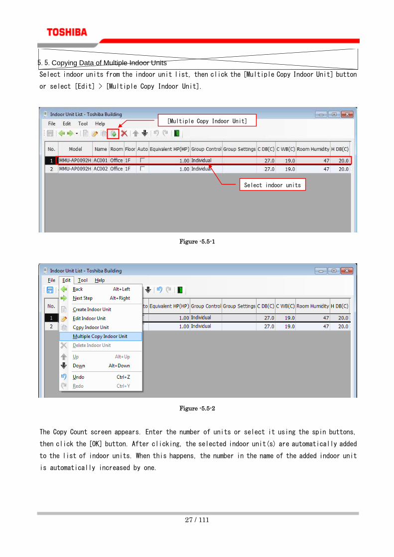
5.5. Copying Data of Multiple Indoor Units
Select indoor units from the indoor unit list, then click the [Multiple Copy Indoor Unit] button
or select [Edit] > [Multiple Copy Indoor Unit].
Figure -5.5-1
Figure -5.5-2
The Copy Count screen appears. Enter the number of units or select it using the spin buttons,
then click the [OK] button. After clicking, the selected indoor unit(s) are automatically added
to the list of indoor units. When this happens, the number in the name of the added indoor unit
is automatically increased by one.
[Multiple Copy Indoor Unit]
button
Select indoor units

28 / 111
Figure -5.5-3
5.6. Undoing the Edit of an Indoor Unit
You can undo the addition, edit, copy, and deletion to restore the previous status. Click the [Undo] button
or select [Edit] > [Undo].
Figure -5.6-1
Figure -5.6-2
[Undo] button

29 / 111
5.7. Redoing the Edit of an Indoor Unit
You can redo the operation undone in "5.6 Undoing the Edit of an Indoor Unit". Click the [Redo] button
or select [Edit] > [Redo].
Figure -5.7-1
Figure -5.7-2
Redo button

30 / 111
5.8. Setting the Outdoor Temperature Information
Enter the “Cooling Dry Bulb Temperature” and “Heating Wet Bulb Temperature” or select them using the
spin buttons.
Figure -5.8-1
5.9. Adding a New Outdoor Unit
To add a new outdoor unit, click the [Create Outdoor Unit] button or select [Edit] > [Create
Outdoor Unit]. When you have finished adding outdoor units and linking indoor units to outdoor
units, click the [Next Step] button to proceed.
Figure -5.9-1
[Create Outdoor Unit]
button

31 / 111
Figure -5.9-2
Clicking the [Create Outdoor Unit] button displays the Outdoor Unit Information screen. On this screen,
enter outdoor unit data such as the name, type, or capacity. After all data has been entered, click the
[Save] button or select [File] > [Save]. The data will be saved, and the outdoor unit will be automatically
added to the outdoor unit list screen.
Figure -5.9-3
[Save] button Outdoor unit data
Outdoor unit
connection image

32 / 111
The following table shows settings that can be entered:
Item Method Note
Refrigerant Cycle Number Entered by user Entry required
Refrigerant Cycle name Entered by user Entry required
Unit Type Selected by user
Capacity Selected by user/Selected
automatically
Entry requiredHigh Efficiency type
can be checked for Auto only
Max Selection Selected by user
Wiring System Name Entered/Selected by user Existing data can be selected from
the drop-down list
Outdoor Unit Position Selected by user
Power Supply method Selected by user
Main Pipe Length (Actual) Entered by user
Main Pipe Length (Equivalent) Entered by user Entry required
Between T-Joints
(Actual)
LA Entered by user Entry requiredOnly S-MMS can be
entered
LB Entered by user Entry requiredOnly S-MMS can be
entered
Between T-Shape to
Outdoor(Equivalent)
LA Entered by user Entry requiredOnly S-MMS can be
entered
LB Entered by user Entry requiredOnly S-MMS can be
entered
Between T-Shape to
Outdoor(Actual)
La Entered by user Entry requiredOnly S-MMS can be
entered
Lb Entered by user Entry requiredOnly S-MMS can be
entered
Lc Entered by user Entry requiredOnly S-MMS can be
entered
Ld Entered by user Entry requiredOnly S-MMS can be
entered
Between T-Shape to
Outdoor(Equivalent)
La Entered by user Entry requiredOnly S-MMS can be
entered
Lb Entered by user Entry requiredOnly S-MMS can be
entered
Lc Entered by user Entry requiredOnly S-MMS can be
entered
Ld Entered by user Entry requiredOnly S-MMS can be
entered
Hight
Difference(H3)
A to B Entered by user Entry requiredOnly S-MMS can be
entered
A to C Entry requiredOnly S-MMS can be
entered
A to D Entry requiredOnly S-MMS can be
entered

33 / 111
5.10. Selecting a Capacity Rank and Max Selection (%)
There are two ways of selecting an outdoor unit capacity rank: Manual selection and Automatic selection
in which the rank is automatically selected according to the selected indoor unit capacity and the
maximum connection percentage.
① Manual selection
Select a capacity and maximum connection (%) from the lists.
② Automatic selection
Select the [Auto] checkbox in Capacity, then the maximum connection (%) from the list.
③ Max Selection(%)
Calculated by multiplying connection capacity by outdoor horsepower (HP). For example, if
MMY-MAP1403H is selected and the maximum connection is set to 120%, indoor units of up to 6
horsepower can be connected. If the maximum connection capacity is exceeded, a warning
message appears.
Figure -5.10-1
If an outdoor unit is selected using [Auto], calculation is performed using the base outdoor
horsepower and maximum connection capacity. When the connection capacity exceeds the
calculated value, the outdoor capacity rank is automatically increased by one.

34 / 111
5.11. Editing Outdoor Unit Data
Select an outdoor unit from the outdoor unit list, then click the [Edit Outdoor Unit] button or select [Edit] >
[Edit Outdoor Unit]. The Outdoor Unit Information screen appears.
Figure -5.11-1
Figure -5.11-2
Alternatively, double-click the outdoor unit name.
Outdoor unit data can be edited on the Configuration of Refrigerant Cycle screen. If the outdoor unit data
is edited, the linked indoor unit will be automatically released.
For how to edit, see "5.9 Adding a New Outdoor Unit" and "5.10 Selecting a Capacity Rank and
Max Selection (%)".
[Edit Outdoor Unit]
button
Select an outdoor
unit

35 / 111
5.12. Copying Outdoor Unit Data
Select an outdoor unit from the outdoor unit list, then click the [Copy Outdoor Unit] button
or select [Edit] > [Copy Outdoor Unit]. After the procedure, the outdoor unit with the same data
is automatically added to the outdoor unit list. When this happens, the number in the name of
the added outdoor unit is automatically increased by one.
Figure -5.12-1
Figure -5.12-2
[Copy Outdoor Unit]
button
Select an outdoor
unit

36 / 111
5.13. Copying Data of Multiple Outdoor Units
Select outdoor units from the outdoor unit list, then click the [Multiple Copy Outdoor Unit]
button or select [Edit] > [Multiple Copy Outdoor Unit].
Figure -5.13-1
Figure -5.13-2
[Multiple Copy Outdoor Unit]
button
Select an outdoor
unit

37 / 111
The Copy Count screen appears. Enter the number of units or select it using the spin buttons,
then click the [OK] button. After clicking, the selected outdoor unit(s) are automatically added
to the list of outdoor units. When this happens, the number in the name of the added outdoor
unit is automatically increased by one.
Figure -5.13-3

38 / 111
5.14. Connecting an Indoor Unit to an Outdoor Unit
Select an outdoor unit from the outdoor unit list. To connect an indoor unit to the selected
outdoor unit, select an indoor unit from the Selectable Indoor Units list, then click the [<<]
(Add) button or drag and drop the indoor unit into the Connected Indoor Units list. If the maximum
outdoor unit capacity is exceeded, a warning message appears.
When you have finished connecting the indoor unit, click the [Next Step] button to proceed.
Figure -5.14-1
[Next Step]
button
Select an indoor
unit
Add button

39 / 111
5.15. Deleting a Connected Indoor Unit
Select an outdoor unit from the outdoor unit list. Select an outdoor unit from the outdoor unit
list. To delete an indoor unit connected to the selected outdoor unit, select the indoor unit,
then click the [>>] (Delete) button or drag and drop it into the Selectable Indoor Units list.
Figure -5.15-1
Select an indoor
unit
Delete button

40 / 111
5.16. Undoing the Edit of an Outdoor Unit or the Connection to an Indoor Unit
You can undo the addition, edit, copy, and deletion to restore the previous status. Click the [Undo]
button or select [Edit] > [Undo].
Figure -5.16-1
Figure -5.16-2
[Undo] button

41 / 111
5.17. Redoing the Edit of an Outdoor Unit or the Connection to an Indoor Unit
You can redo the operation undone in "5.16 Undoing the Edit of an Outdoor Unit or the Connection to
an Indoor Unit". Click the [Redo] button or select [Edit] > [Redo].
Figure -5.17-1
Figure -5.17-2
Redo button

42 / 111
5.18. Creating the Piping Diagram
The piping diagram is automatically created. The automatically created piping diagram uses
T-Joint. The piping size is automatically calculated according to the connected indoor unit,
and is displayed on the diagram. The units are displayed in the order of their addition to the
Connected Indoor Units list. The highlighted lines in the Indoor Unit List indicate already piped
indoor units. The white lines indicate units not yet piped. If the diagram has no problems, click
the [Next Step] button to proceed.
Figure -5.18-1
[Next Step]
button
Already
piped
Not yet
piped

43 / 111
5.19. Changing the Joint Type
Drag a joint type that you want to change from the Joint List. Next, drop it on the joint that
you want to change to change it. If the joint is changed, the piping is automatically redrawn
to suit the new joint.
If the Pipe Rule Check is enabled, the Pipe Length screen appears. For how to enter the pipe
length, see "5.20 Entering the Length between the Joints".
Figure -5.19-1
Drag
Drop

44 / 111
5.20. Entering the Length between the Joints
Double-click a joint. The Pipe Length screen appears. Enter the lengths then click the [OK] button.
The lengths are automatically displayed and the sizes are calculated and displayed on the diagram.
Figure -5.20-1
Double-click

45 / 111
5.21. Deleting a Joint/Indoor Unit from the Piping Diagram
Right-click the joint or indoor unit on the diagram. Select [Delete] from the displayed menu.
The dummy indoor unit appears in place of the indoor unit deleted from the diagram. In the Indoor
Unit List, the background color of the deleted indoor unit becomes white. If a joint is deleted,
any indoor units connected to the joint are also deleted.
Figure -5.21-1
When deleting a Y-shape branching joint, a screen appears prompting you to select a branch to delete.
After a branch is selected, you can change the method to delete the joint and branch.
Menu

46 / 111
Figure 5.21-2
When "Remove Both Branches and Joint" is selected, the selected joint and all the branches connected
to the joint will be deleted.
47 / 111
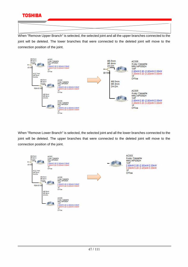
When "Remove Upper Branch" is selected, the selected joint and all the upper branches connected to the
joint will be deleted. The lower branches that were connected to the deleted joint will move to the
connection position of the joint.
When "Remove Lower Branch" is selected, the selected joint and all the lower branches connected to the
joint will be deleted. The upper branches that were connected to the deleted joint will move to the
connection position of the joint.

48 / 111
5.22. Inserting a Page Break
For each joint, you can insert a page break into a piping diagram output as project data.
Right-click the joint to insert a page break into. Select [Show page breaks] from the displayed
menu.
Figure -5.22-1
The model name of the joint with a page break turns orange, and [Show page breaks] is checked.
If [Show page breaks] is clicked for the joint with a page break, the inserted page break is
deleted.
Figure -5.22-2
Menu

49 / 111
5.23. Undoing the Edit of a Piping Diagram
You can undo the addition, edit, and deletion of the joint, the position of an indoor unit, etc. Click the
[Undo] button or select [Edit] > [Undo].
Figure -5.23-1
Figure -5.23-2
5.24. Redoing the Edit of a Piping Diagram
You can redo the operation undone in "5.23 Undoing the Edit of a Piping Diagram". Click the [Redo]
button or select [Edit] > [Redo].
Figure -5.24-1
Figure -5.24-2
[Undo] button
Redo button
50 / 111
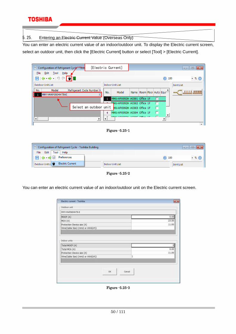
5.25. Entering an Electric Current Value (Overseas Only)
You can enter an electric current value of an indoor/outdoor unit. To display the Electric current screen,
select an outdoor unit, then click the [Electric Current] button or select [Tool] > [Electric Current].
Figure -5.25-1
Figure -5.25-2
You can enter an electric current value of an indoor/outdoor unit on the Electric current screen.
Figure -5.25-3
Select an outdoor unit
[Electric Current]
button

51 / 111
5.26. Setting the Central Controller/BMS System Setting
Up to 10 devices can be connected on a single TCC-LINK line. When a BMS system is selected one
BMS control device interface is connected, so up to 9 central controllers can be connected. When
you have finished configuring the settings, click the [Next Step] button to proceed.
Figure -5.26-1
① Specify the number of units for Compliant Manager, 64 Central Remote Controller, and ON-OFF
Controller in Central Remote Controller. Click the [Settings] button to set the central remote
controller.
Figure -5.26-2
[Next Step]
button

52 / 111
② Select Touch Screen Controller or Web Based Controller for a BMS system. When Web Based
Controller is selected, you can set the TCC-LINK line for the controller.
Figure 5.26-3
Figure 5.26-4
③ Select BACNet for Open Network System.

53 / 111
5.27. Outputting Project Data
Click the [Output Drawing and Data] button or select [Edit] > [Output Drawing and Data].
Figure -5.27-1
Figure -5.27-2
The Output type selection screen appears. Select the output format.
Figure -5.27-3
[Output Drawing and Data]
button

54 / 111
The Save screen appears. Select the destination folder, then click the [OK] button. When the
output starts, the following message appears:
Figure -5.27-4
When the output is complete, a completion dialog box appears. Click the [OK] button.
Figure -5.27-5
Confirm the output file.

55 / 111
5.28. Copying a Document to the Destination Folder of Project Data
You can copy a local document of the settings to the destination folder of project data.
Selecting a document copies the document when project data is output. When the "Select All" button is
clicked, all the documents are checked. Similarly, when the "Clear All" button is clicked, all the checked
documents are cleared.
Click the [Preview] button to preview the local document.
Figure -5.28-1
56 / 111
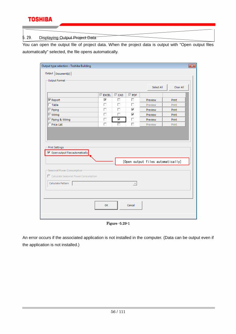
5.29. Displaying Output Project Data
You can open the output file of project data. When the project data is output with "Open output files
automatically" selected, the file opens automatically.
Figure -5.29-1
An error occurs if the associated application is not installed in the computer. (Data can be output even if
the application is not installed.)
[Open output files automatically]

57 / 111
5.30. Previewing Project Data
You can preview project data before outputting it. Select a checkbox of a project to preview. The Preview
button can be clicked for each type of the selected project.
Figure -5.30-1
When the [Preview] button is clicked, the following message appears:
Figure -5.30-2
Preview

58 / 111
When the preparation is complete, the preview of the selected project appears.
Figure -5.30-3
You can also print from the Preview screen. To print, click the [Print] button.
Figure -5.30-4
[Print] button

59 / 111
5.31. Printing Project Data
You can display the Print screen before outputting project data. Select a checkbox of a project to print.
The Print button can be clicked for each type of the selected project.
Figure -5.31-1
When the [Print] button is clicked, the following message appears: When the [OK] button is clicked, the
print starts.
Figure -5.31-2

60 / 111
6. Drag & Drop Drawing
6.1. Setting the Outdoor Temperature Information
Click the [Outdoor Temperature Information] button or select [Edit] > [Outdoor Temperature Information].
Figure -6.1-1
Figure -6.1-2
When the outdoor temperature information screen opens, enter the “Cooling Dry Bulb Temperature” and
“Heating Wet Bulb Temperature” or select them using the spin buttons.
Figure -6.1-3
[Outdoor Temperature
Information] button

61 / 111
6.2. Creating a New Piping Diagram
Click the [New] button or select [Edit] > [New].
Figure -6.2-1
Figure -6.2-2
[New] button

62 / 111
6.3. Adding a New Indoor Unit
Drag an indoor unit from the indoor unit list and drop it onto a dummy indoor unit. For edit
indoor unit data, see "5.1 Adding a New Indoor Unit" and "5.2 Selecting a Capacity Rank".
Figure -6.3-1
Indoor unit model
icons (Drag)
Drop

63 / 111
6.4. Editing Indoor Unit Data
Double-click an indoor unit on the piping diagram. For edit indoor unit data, see "5.1 Adding
a New Indoor Unit" and "5.2 Selecting a Capacity Rank".
Figure -6.4-1
Double-click

64 / 111
6.5. Copying Indoor Unit Data
Right-click an indoor unit on the piping diagram. Select [Copy] from the displayed menu.
Figure -6.5-1
Menu

65 / 111
Right-click a dummy indoor unit. Select [Paste] from the displayed menu to add an indoor unit.
When this happens, the number in the name of the added indoor unit is automatically increased
by one.
Figure -6.5-2
Menu

66 / 111
6.6. Editing Outdoor Unit Data
Double-click the outdoor unit on the piping diagram. For how to edit, see "5.9 Adding a New
Outdoor Unit" and "5.10 Selecting a Capacity Rank and Max Selection (%)".
Figure -6.6-1
Double-click

67 / 111
6.7. Changing the Joint Type
See "5.19 Changing the Joint Type".
6.8. Entering the Length between the Joints
See "5.20 Entering the Length between the Joints".
6.9. Deleting a Joint/Indoor Unit from the Piping Diagram
See "5.21 Deleting a Joint/Indoor Unit from the Piping Diagram".
6.10. Inserting a Page Break
See "5.22 Inserting a Page Break".
6.11. Undoing the Edit of a Piping Diagram
See "5.23 Undoing the Edit of a Piping Diagram".
6.12. Redoing the Edit of a Piping Diagram
See "5.24 Redoing the Edit of a Piping Diagram".
6.13. Entering an Electric Current Value (Overseas Only)
See "5.25 Entering an Electric Current Value (Overseas Only)".

68 / 111
6.14. Editing the Piping Diagram
Select the piping diagram, then click the [Edit] button or select [Edit] > [Edit].
Figure -6.14-1
Figure -6.14-2
Select piping
diagram
[Edit] button

69 / 111
Alternatively, double-click the piping diagram.
Figure -6.14-3
For how to edit the diagram, see "6.3 Adding a New Indoor Unit" – "6.9 Deleting a Joint/Indoor
Unit from the Piping Diagram".
Double-click

70 / 111
6.15. Copying the Piping Diagram
Select the piping diagram, then click the [Copy] button or select [Edit] > [Copy]. A copy of
the piping diagram will be created.
Figure -6.15-1
Figure -6.15-2
Select piping
diagram
[Copy] button

71 / 111
6.16. Setting the Central Controller/BMS System Setting
Click the [Central Controller / BMS System Setting] button or select [Edit] > [Central Controller
/ BMS System Setting]. See "5.26 Setting the Central Controller/BMS System Setting".
Figure -6.16-1
Figure -6.16-2
[Central Controller / BMS System Setting]
button

72 / 111
6.17. Outputting Project Data
Click the [Output Drawing and Data] button or select [Edit] > [Output Drawing and Data]. See
"5.27 Outputting Project Data".
Figure -6.17-1
Figure -6.17-2
[Output Drawing and Data]
button

73 / 111
7. Selecting in Quotation Mode
7.1. Using the Quotation Mode to Start System Selection
Click the [New Quotation Mode] button or select [Tools] > [Quotation Mode] > [New].
Figure -7.1-1
Figure -7.1-2
Figure -7.1-3
[New Quotation Mode] button

74 / 111
7.2. Entering System Information
You can enter system information in [System Information] in the [Setting] tab.
Figure -7.2-1
The following table shows items that can be entered/referred to:
Item Method Note
Project Name Entered by user Entry required
Customer name Entered by user Entry required
Total Capacity Code Automatically
entered
Total Cooling Capacity Automatically
entered
Total Cooling Sensible Capacity Automatically
entered
Total Heating Capacity Automatically
entered
Number of Connected Indoor Units Automatically
entered
Indoor (HP) / Outdoor (HP) Ratio Automatically
entered
[System Information]

75 / 111
7.3. Entering the Outdoor Unit Setting
You can enter outdoor unit information in [Outdoor unit setting] in the [Setting] tab.
Figure -7.3-1
The following table shows items that can be entered/referred to:
Item Method Note
Unit Type Selected by
user
Outdoor Model Selected by
user
Cooling Temperature (DB) Entered by user
Heating Temperature (WB) Entered by user
Max Selection Selected by
user
Cooling Capacity Automatically
entered
Heating Capacity Automatically
entered
[Outdoor unit setting]

76 / 111
7.4. Entering the Indoor Unit Setting
You can enter indoor unit information in [Indoor unit setting] in the [Setting] tab.
Figure -7.4-1
The following table shows items that can be entered/referred to:
Item Method Note
Fan Speed Selected by
user
Indoor Cooling Dry Bulb Temperature Entered by user
Indoor Cooling Wet Bulb Temperature Entered by user
Room Humidity Entered by user
Indoor Heating Dry Bulb Temperature Entered by user
Piping length from Outdoor
(Equivalent)
Entered by user
Piping length from Outdoor (Actual) Entered by user
Height difference between Indoor and
Outdoor
Entered by user
Height difference between Indoors Entered by user
Remote controller Selected by
user
[Indoor unit setting]

77 / 111
7.5. Selecting an Indoor Unit
You can enter the number of indoor units to connect in [Quantity] in the [Selection] tab. Changing
the number of indoor units also changes the system status.
Figure -7.5-1
If the number of connected indoor units and the capacity exceed the connectable number capacity
of outdoor units, the following message appears and the number entry is cancelled.
Figure -7.5-2
[Quantity] area

78 / 111
7.6. Entering an Electric Current Value (Overseas Only)
See "5.25 Entering an Electric Current Value (Overseas Only)".
7.7. Outputting Project Data
Click the [Output Drawing and Data] button or select [Edit] > [Output Drawing and Data]. See
"5.27 Outputting Project Data".
8. Configuring Various Settings
Configure various function settings of Selection Tool. Select [Tool] > [Preferences].
Figure 8--7.7-1

79 / 111
8.1. Configuring the Display/Unit Settings
Configure the main menu display settings and unit settings used for output.
Figure -8.1-1

80 / 111
8.2. Setting the Design Condition
Set the default values of indoor/outdoor units. If the default values are changed, the various
settings of indoor/outdoor units are set to the values when the units are newly added.
Figure -8.2-1
8.3. Setting the Specification Check
Configure the settings of Piping specification check, Indoor unit data check, and Equipment
length calculation. The default setting is that Piping specification check and Indoor unit data
check are to be performed.
Figure -8.3-1

81 / 111
① Piping Rule Check
Select whether to check the piping rules provided by design manual. If the checkbox is selected, the
following rules are checked: the total length is 180 m or less (excluding PMV Kit); the indoor unit
farthest from the first branch is within 35 m; the length of the main pipe is 65 m or less, etc.
If the checkbox is not selected, no piping rules are checked and they are no longer required entry
items.
② Outdoor unit Pipe Length Check
Select whether to check if the pipe length is entered on the outdoor unit data screen.
If the checkbox is selected, a warning message will appear if the pipe length of the outdoor unit
created/edited on the outdoor unit data screen is not entered.
If the checkbox is not selected, entry is not checked and it is no longer a required entry item.
③ Indoor Unit Piping Length and Height Difference Check
Select whether to check if the pipe length and height are entered on the indoor unit data screen. If the
checkbox is selected, a warning message will appear if the pipe length and height of the indoor unit
created/edited on the indoor unit data screen are not entered.
If the checkbox is not selected, entry is not checked and it is no longer a required entry item.
④ Indoor unit Cooling Data Check
Select whether to check if the cooling data is entered on the indoor unit data screen. If the checkbox
is selected, a warning message will appear if the temperature data and cooling capacity for Auto are
not entered.
In addition, selection by sensible capacity only is possible. If selected by sensible capacity only, the
cooling rated capacity of the indoor unit will not be used for system selection.
If the checkbox is not selected, entry is not checked and it is no longer a required entry item.
⑤ Indoor unit Heating Data Check
Select whether to check if the warming data is entered on the indoor unit data screen. If the checkbox
is selected, a warning message will appear if the temperature data and heating capacity for Auto are
not entered.
If the checkbox is not selected, entry is not checked and it is no longer a required entry item.
82 / 111
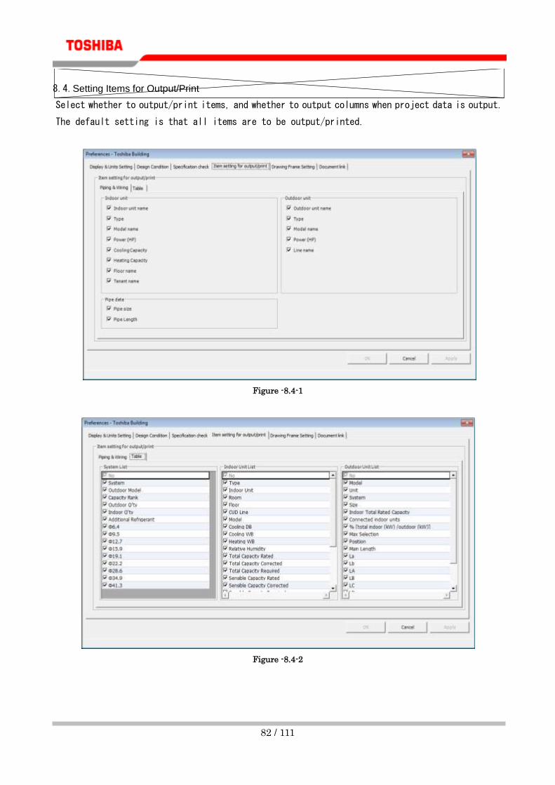
8.4. Setting Items for Output/Print
Select whether to output/print items, and whether to output columns when project data is output.
The default setting is that all items are to be output/printed.
Figure -8.4-1
Figure -8.4-2

83 / 111
8.5. Setting the Drawing Frame
Set the items to be displayed for the drawing frame. Entering the drawing frame name allows you
to register the frame as a database. If the [New] button is clicked while the project is being
edited, the building name from the project information is automatically displayed. When the
screen is opened from the main screen, the entry fields are blank, and the date is that which
is displayed on the computer.
Figure -8.5-1
8.6. Setting the Document Link
You can set the links of the URL and local document.
Figure -8.6-1

84 / 111
If the URL link is set, you can jump to the URL from the indoor/outdoor unit information entry screen.
Figure -8.6-2
To the Local Document Links, you can register a file that can be distributed with project data when it is
output. The available file format are *.xls, *.xlsx, *.doc, *.docx, and *.pdf.
You can add local document links by clicking the [Add] button. To edit an already-registered local
document link, click the [Edit] button. To delete an already-registered local document link, click the
[Delete] button.
Figure -8.6-3
URL link

85 / 111
9. Setting the Calculation Pattern of Seasonal Power Consumption
9.1. Creating a New Calculation Pattern of Seasonal Power Consumption
The seasonal power consumption can be calculated using the system selection data. Select [Tools] >
[Seasonal Power Consumption].
Figure -9.1-1
To create/edit the calculation pattern of the Seasonal Power Consumption, select [Tools] >
[Seasonal Power Consumption] > [Setting].
Figure -9.1-2

86 / 111
Figure -9.1-3

87 / 111
To create a new pattern, click the [Add Calculation Pattern] button, select [Edit] > [Add
Calculation Pattern], or select [New] from the Calculation Pattern combo box.
Figure -9.1-4
Figure -9.1-5
Figure -9.1-6-
[Add Calculation Pattern]
button

88 / 111
9.2. Editing the Calculation Pattern of Seasonal Power Consumption
Select a calculation pattern from the Calculation Pattern combo box.
① Calculation Name
Set the calculation pattern name. An existing name cannot be set.
Figure -9.2-1
② Country
Select a target country for the calculation of Seasonal Power Consumption.
Figure -9.2-2
③ City
Select a target city for the calculation of Seasonal Power Consumption. The list of the cities varies
depending on the selected country.
Figure -9.2-3
④ Type
Select the air-conditioner type.
Figure -9.2-4

89 / 111
⑤ Cooling Setting Temp./ Heating Operation Temp.
Select a temperature for the calculation of Seasonal Power Consumption.
Figure -9.2-5
⑥ Cooling Operating Period/ Heating Operating Period
Set the operating period for the calculation of Seasonal Power Consumption.
Figure -9.2-6

90 / 111
⑦ Operating time
Set the operating time for each day of the week. Clicking a cell selects/deselects the hour. Also,
multiple cells can be selected simultaneously by selecting a range, line or column.
Figure -9.2-7
91 / 111
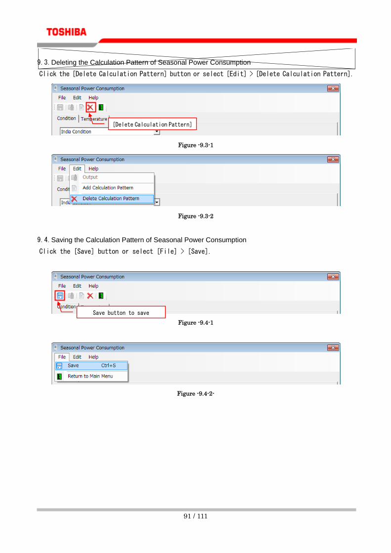
9.3. Deleting the Calculation Pattern of Seasonal Power Consumption
Click the [Delete Calculation Pattern] button or select [Edit] > [Delete Calculation Pattern].
Figure -9.3-1
Figure -9.3-2
9.4. Saving the Calculation Pattern of Seasonal Power Consumption
Click the [Save] button or select [File] > [Save].
Figure -9.4-1
Figure -9.4-2-
[Delete Calculation Pattern]
button
Save button to save
calculation pattern

92 / 111
9.5. Outputting Seasonal Power Consumption without Creating a Project
You can output Seasonal Power Consumption without creating a project.
Select an outdoor unit model, and click the Add button, or drag and drop it into [Outdoor Unit
List].
To delete a registered outdoor unit, select an outdoor unit from [Outdoor Unit List], and click
the Delete button, or drag and drop it into the selectable outdoor unit list.
Figure -9.5-1
Select an outdoor unit [Outdoor Unit List]
Add button

93 / 111
When one or more outdoor units are added, the [Output] button and the menu [Edit] > [Output]
are enabled. Clicking the button or menu displays the Output dialog box. When the destination
is entered, the output starts.
Figure -9.5-2
After a file is output, confirm the file.

94 / 111
10. Importing the Temperature Data
The temperature data for each city can be imported. Select [Tools] > [Seasonal Power Consumption] >
[Temperature Data Import].
Figure -10-1
10.1. Selecting a Temperature Data File
Click the [Open] button or [Browse] button, or select [File] > [Open].
Figure -10.1-1
Figure -10.1-2
Open button
Browse button

95 / 111
The Open dialog box appears. Select a file to import.
The following formats are available:
File type Excel 97 - 2003
Extension .xls
Column 1 Month
Column 2 Day
Column 3 Hour
Column 4 DBT(C)
When a file is selected, the file path appears in the text box.
Figure -10.1-3
10.2. Specifying a Country
Enter a country name in the combo box, or select a country from the list. If the entered country name is not
in the list, the country data is newly added when imported. If it is in the list, the data is overwritten.
Figure -10.2-1

96 / 111
10.3. Selecting a City
Enter a city name in the combo box, or select a city from the list. If the entered city name is not in the list,
the city data is newly added when imported. If it is in the list, the data is overwritten.
Figure -10.3-1
10.4. Starting the Import
Click the [Import] button, or select [File] > [Import].
Figure -10.4-1
Figure -10.4-2
Import button

97 / 111
When the import is complete, the data is saved.
Figure -10.4-3

98 / 111
11. Exporting the Temperature Data
The temperature data for each city can be exported. Select [Tools] > [Seasonal Power Consumption] >
[Temperature Data Export].
Figure -11-1
11.1. Specifying the Export Destination
Click the [Open] button or [Browse] button, or select [File] > [Open]. The Open dialog box appears. Select
a file to export the data to.
Figure -11.1-1
Figure -11.1-2
Open button
Browse button

99 / 111
When the destination is selected, the file path appears in the text box.
Figure -11.1-3
11.2. Selecting the File Type
Select the File Type from the Export Data Category combo box.
Figure -11.2-1
The following table shows data content exported for each type:
New Template Export a temperature data file template.
All Export temperature data targeting all countries and cities.
All Areas Export temperature data targeting all cities of the selected country.
Selected Area Export temperature data targeting the selected country and city.
11.3. Specifying a Country
Select a country from the list. If the selected type is “New Template” or “All”, a country cannot be selected.
Figure -11.3-1

100 / 111
11.4. Selecting a City
Select a city from the list. If the selected type is “New Template”, “All” or “All Areas”, a city cannot be
selected.
Figure -11.4-1
11.5. Starting the Export
Click the [Export] button, or select [File] > [Export].
When the export is complete, the data is saved to the specified file.
Figure -11.5-1

101 / 111
12. Outputting the Calculation Report of Seasonal Power Consumption
The calculation report of Seasonal Power Consumption can be output using the system selection data
and specified calculation pattern.
Figure -12-1
Select the "Calculate Seasonal Power Consumption" checkbox on the Output type selection screen
to output the calculation report of Seasonal Power Consumption along with another output file.
Figure -12-2
If no calculation pattern is created, the calculation report of Seasonal Power Consumption can
be output. To create a calculation pattern, see "9.1 Creating a New Calculation Pattern of
Seasonal Power Consumption".
Click the [OK] button. The calculation report of Seasonal Power Consumption will be output as a file of the
selected format.

102 / 111
13. Setting the Price List
You can set the price for units in each project from the main screen.
13.1. Setting the Price List from the Main Screen
If you set the price list from the main screen, the price list that is set is copied to new projects
that you make.
To open the price list from the main screen, select [Tools] > [Price List].
Figure -13.1-1
Figure -13.1-2

103 / 111
13.1.1. Importing the Price List
To import the price list, select [File] > [Price List] > [Import]. The Open dialog box appears. Select a file to
import.
Figure -13.1.1-1
Figure -13.1.1-2
If you click the OK button in the confirmation message, the file selection dialog box opens;
select a file to import.
A message appears when the price list is successfully imported and the file that was imported
appears on the Price List screen.
Figure -13.1.1-3

104 / 111
Figure -13.1.1-4
13.1.2. Changing Prices on the Price List
You can change the prices by changing the price row.
Figure -13.1.2-5

105 / 111
13.1.3. Saving Changes to the Price List
To save the changes to the price list, click the [Save] button or select [File] > [Save].
Figure -13.1.3-6
Figure -13.1.3-7
13.1.4. Exporting the Price List
To export the price list, select [File] > [Price List] > [Export]. The Open dialog box appears. Select a file to
export the data to.
Figure -13.1.4-8
When the export is complete, the price list is saved to the selected file.
Figure -13.1.4-9
13.2. Setting the Price List for an Entire Project
You can also set the price list for an entire project.
[Save] button

106 / 111
If the data for the entire project is not set, copy the data that was set in "13.1 Setting the
Price List from the Main Screen" and use it.
It is possible to handle special discounts and price adjustments without affecting other projects
or the prices lists set on the main menu because the price data for each unit is managed separately
for each project.
13.2.1. To Open the Price List Screen with a Wizard
Open the print and system check screen, and select [Tools] > [Price List].
Figure -13.2.1-1
13.2.2. To Open the Price List Screen by Dragging and Dropping
Open the system list screen and select [Tools] > [Price List].
Figure -13.2.2-2
13.2.3. Importing the Price List
See "13.1.1 Importing the Price List" for the operating procedure.
13.2.4. Changing Prices on the Price List
See "13.1.2 Changing Prices on the Price List" for the operating procedure.
13.2.5. Saving Changes to the Price List
See "13.1.3 Saving Changes to the Price List" for the operating procedure.

107 / 111
13.2.6. Exporting the Price List
See "13.1.4 Exporting the Price List" for the operating procedure.
13.2.7. To Open the Price List Screen with a Wizard
To output the price list from a wizard, click the [Output Drawing and Data] button or select
[Edit] > [Output Drawing and Data].
Figure -13.2.7-3
Figure -13.2.7-4
[Output Drawing and Data]
button

108 / 111
The Output type selection screen appears, select a price list.
Figure -13.2.7-5
The Save screen appears. Select the destination folder, then click the [OK] button. When the
output starts, the following message appears:
Figure -13.2.7-6
When the output is complete, a completion dialog box appears. Click the [OK] button.
Figure -13.2.7-7
Confirm the output file.

109 / 111
13.2.8. To Open the Price List Screen by dragging and dropping
To Open the Price List Screen by dragging and dropping, click the [Output Drawing and Data] button
or select [Edit] > [Output Drawing and Data]. See "13.2.7 To Open the Price List Screen with a
Wizard".
Figure -13.2.8-8
Figure -13.2.8-9
[Output Drawing and Data]
button

110 / 111
14. TOSHIBA CARRIER SOFTWARE LICENSE AGREEMENT
IMPORTANT: PLEASE READ TERMS AND CONDITIONS OF THIS AGREEMENT CAREFULLY
BEFORE USING “Selection Tool SOFTWARE” (HEREINAFTER CALLED “THE SOFTWARE”). BY
USING OR INSTALLING A WHOLE OR A PART OF THIS SOFTWARE, YOU(HEREINAFTER CALLED
“USER”) ARE DEEMED TO ACCEPT ALL THE TERMS AND CONDITIONS OF THIS AGREEMENT. IF
USER DO NOT AGREE TO THESE TERMS AND CONDITIONS, DO NOT USE OR INSTALL THE
SOFTWARE AND RETURN TO THE LOCATION FROM WHITCH IT WAS OBTAINED.
1. For the purpose of this Agreement, ”Software” means the computer programs and information and data
(including without limitation electric documents) contained in the media or files distributed with this
Agreement., except those specifically excluded not as a part of the software in writing.
2. The Software is the property of Toshiba Carrier Corporation. Toshiba Carrier Corporation owns all
intellectual properties in the software. User may use the Software only in accordance with the terms
and conditions of this Agreement, and only for such purpose as designated by Toshiba Carrier
Corporation or as agreed to by Toshiba Carrier Corporation.
3. Toshiba Carrier Corporation owns the copyright of the software and data in the software. The software
is protected under applicable copyright law and international conventions.
4. User may copy and install this Software for such purpose as described in the documents of the
Software. Any copy created by User shall be immediately destroyed immediately after necessity of
such copy are ended. With an exception of the forgoing, User shall not make any copy of the Software;
5. User shall not reverse engineer, decompile, disassemble, or modify the Software.
6. User shall not use the software with plural people within any internal network or Internet.
7. User shall not distribute, transfer, rent, lease, or sell its right to use the Software to anyone.
8. User shall respect the intellectual property right of the software. User understand the confidential
nature of the Software and agrees to safeguard the software from disclosure to any third party.
9. User shall comply with the Foreign Exchange and Foreign Trade Control Laws and other related export
regulations applicable in Japan. User shall comply with the U.S Export Administration Regulations ,
export control laws and regulations of all other countries.

111 / 111
10. THIS SOFTWARE ARE PROVIDED “AS IS” WITHOUT ANY WARRANTY OF ANY KIND, EITHER
EXPRESS OR IMPLIED, INCLUDING, BUT NOT LIMITED TO, THE IMPLIED WARRANTY AND
FITNESS FOR A PARTICULAR PURPOSE. TOSHIBA CARRIER CORPORATION HEREBY
DISCLAIMS ANY WARRANTIES RELATING TO QUALITY AND PERFORMANCE OF THE
SOFTWARE. TOSHIBA CARRIER CORPORATION SHALL NOT BE LIABLE FOR ANY DAMAGES,
LOSSES, EXPENSES OR COSTS, IF ANY, INCURRED IN CONNECTION WITH OR AS A RESULT
OF THE USE OF THE SOFTWARE.
Toshiba Carrier Corporation reserve a right to make modification or improvement of the software at any
time.
11. In the case of breach any terms and conditions of this Agreement, or this Agreement be terminated or
expired, User shall de-install the Software, scrap the Software any/or return the media and/or the files
of Software to Toshiba Carrier Corporation immediately, along with any remaining copies thereof.
12. Toshiba Carrier Corporation may request User to stop using the Software at any time upon notice to
USER.
13. This Agreement are governed and construed by the laws of Japan.
Kumanovska 14, 11000 Beograd, SrbijaTel.: 011 383 68 86, 308 57 40
Faks 011 344 41 13E-mail: [email protected]
www.airtrend.rswww.toshiba-klima.rs • www.toshiba-estia.rs
Kumanovska 14, 11000 Beograd, Srbija
Tel.: 011 308 57 40Faks 011 344 41 13
E-mail: [email protected]