operating instructions and parts manual horizontal band...
TRANSCRIPT

Operating Instructions and Parts Manual Horizontal Band Saw Models HBS-916W; HBS-1018W
JET 427 New Sanford Road LaVergne, Tennessee 37086 Part No. M-414468 Ph.: 800-274-6848 Revision H 01/2016 www.jettools.com Copyright © 2016 JET
2
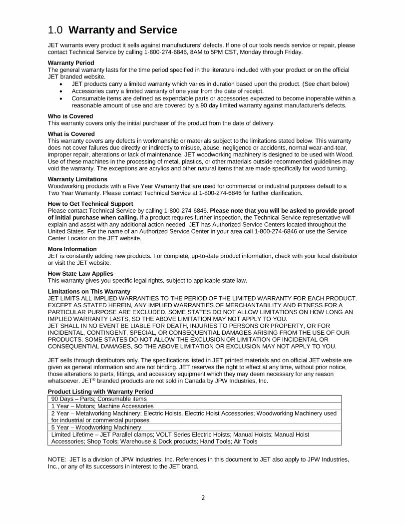
1.0 Warranty and Service JET warrants every product it sells against manufacturers’ defects. If one of our tools needs service or repair, please contact Technical Service by calling 1-800-274-6846, 8AM to 5PM CST, Monday through Friday.
Warranty Period The general warranty lasts for the time period specified in the literature included with your product or on the official JET branded website.
• JET products carry a limited warranty which varies in duration based upon the product. (See chart below) • Accessories carry a limited warranty of one year from the date of receipt. • Consumable items are defined as expendable parts or accessories expected to become inoperable within a
reasonable amount of use and are covered by a 90 day limited warranty against manufacturer’s defects.
Who is Covered This warranty covers only the initial purchaser of the product from the date of delivery.
What is Covered This warranty covers any defects in workmanship or materials subject to the limitations stated below. This warranty does not cover failures due directly or indirectly to misuse, abuse, negligence or accidents, normal wear-and-tear, improper repair, alterations or lack of maintenance. JET woodworking machinery is designed to be used with Wood. Use of these machines in the processing of metal, plastics, or other materials outside recommended guidelines may void the warranty. The exceptions are acrylics and other natural items that are made specifically for wood turning.
Warranty Limitations Woodworking products with a Five Year Warranty that are used for commercial or industrial purposes default to a Two Year Warranty. Please contact Technical Service at 1-800-274-6846 for further clarification.
How to Get Technical Support Please contact Technical Service by calling 1-800-274-6846. Please note that you will be asked to provide proof of initial purchase when calling. If a product requires further inspection, the Technical Service representative will explain and assist with any additional action needed. JET has Authorized Service Centers located throughout the United States. For the name of an Authorized Service Center in your area call 1-800-274-6846 or use the Service Center Locator on the JET website.
More Information JET is constantly adding new products. For complete, up-to-date product information, check with your local distributor or visit the JET website.
How State Law Applies This warranty gives you specific legal rights, subject to applicable state law.
Limitations on This Warranty JET LIMITS ALL IMPLIED WARRANTIES TO THE PERIOD OF THE LIMITED WARRANTY FOR EACH PRODUCT. EXCEPT AS STATED HEREIN, ANY IMPLIED WARRANTIES OF MERCHANTABILITY AND FITNESS FOR A PARTICULAR PURPOSE ARE EXCLUDED. SOME STATES DO NOT ALLOW LIMITATIONS ON HOW LONG AN IMPLIED WARRANTY LASTS, SO THE ABOVE LIMITATION MAY NOT APPLY TO YOU. JET SHALL IN NO EVENT BE LIABLE FOR DEATH, INJURIES TO PERSONS OR PROPERTY, OR FOR INCIDENTAL, CONTINGENT, SPECIAL, OR CONSEQUENTIAL DAMAGES ARISING FROM THE USE OF OUR PRODUCTS. SOME STATES DO NOT ALLOW THE EXCLUSION OR LIMITATION OF INCIDENTAL OR CONSEQUENTIAL DAMAGES, SO THE ABOVE LIMITATION OR EXCLUSION MAY NOT APPLY TO YOU. JET sells through distributors only. The specifications listed in JET printed materials and on official JET website are given as general information and are not binding. JET reserves the right to effect at any time, without prior notice, those alterations to parts, fittings, and accessory equipment which they may deem necessary for any reason whatsoever. JET® branded products are not sold in Canada by JPW Industries, Inc.
Product Listing with Warranty Period 90 Days – Parts; Consumable items 1 Year – Motors; Machine Accessories 2 Year – Metalworking Machinery; Electric Hoists, Electric Hoist Accessories; Woodworking Machinery used for industrial or commercial purposes 5 Year – Woodworking Machinery Limited Lifetime – JET Parallel clamps; VOLT Series Electric Hoists; Manual Hoists; Manual Hoist Accessories; Shop Tools; Warehouse & Dock products; Hand Tools; Air Tools
NOTE: JET is a division of JPW Industries, Inc. References in this document to JET also apply to JPW Industries, Inc., or any of its successors in interest to the JET brand.

3
2.0 Table of Contents 1.0 Warranty and Service ..................................................................................................................................... 2 2.0 Table of Contents ........................................................................................................................................... 3 3.0 Safety warnings .............................................................................................................................................. 4 4.0 Introduction .................................................................................................................................................... 5 5.0 Specifications ................................................................................................................................................. 6 6.0 Uncrating and cleanup ................................................................................................................................... 7 7.0 Installation ...................................................................................................................................................... 7 8.0 Assembly ........................................................................................................................................................ 7 9.0 Electrical connections .................................................................................................................................... 8 10.0 Controls ........................................................................................................................................................ 8 11.0 Prior to Operation ......................................................................................................................................... 8 12.0 Adjustments ................................................................................................................................................. 9
12.1 Adjusting vise square to blade ................................................................................................................. 9 12.2 Changing blade speeds ............................................................................................................................ 9 12.3 Adjusting feed rate ................................................................................................................................... 9 12.4 Changing blades ...................................................................................................................................... 9 12.5 Blade tracking adjustment ...................................................................................................................... 10 12.6 Automatic shut-off adjustment ................................................................................................................ 10 12.7 Thrust roller adjustment .......................................................................................................................... 10 12.8 Guide roller adjustment .......................................................................................................................... 11 12.9 Bow weight adjustment .......................................................................................................................... 11 12.10 Vise adjustment .................................................................................................................................... 11
13.0 Maintenance ............................................................................................................................................... 11 13.1 Lubrication .............................................................................................................................................. 12
14.0 Replacement Parts ..................................................................................................................................... 12 14.1.1 HBS-916W & HBS-1018W – Base and Bed Assembly – Exploded View ........................................... 13 14.1.2 HBS-916W only – Saw Arm Assembly – Exploded View .................................................................... 14 14.1.3 HBS-1018W only – Saw Arm Assembly – Exploded View .................................................................. 15 14.1.4 Parts List for HBS-916W, HBS-1018W ............................................................................................... 16 14.2.1 HBS-916W & 1018W – Gear Speed Reducing Box – Exploded View ................................................ 23 14.2.2 HBS-916W & 1018W – Gear Speed Reducing Box – Parts List ......................................................... 24
15.0 Electrical Connections ................................................................................................................................ 25 15.1 Electrical Connections – HBS-916W only .............................................................................................. 25 15.2 Electrical Connections – HBS-1018W only ............................................................................................ 26

4
3.0 Safety warnings 1. Read and understand the entire owner’s manual before attempting assembly or operation.
2. Read and understand the warnings posted on the machine and in this manual. Failure to comply with all of these warnings may cause serious injury.
3. Replace the warning labels if they become obscured or removed.
4. This band saw is designed and intended for use by properly trained and experienced personnel only. If you are not familiar with the proper and safe operation of a band saw, do not use until proper training and knowledge have been obtained.
5. Do not use this band saw for other than its intended use. If used for other purposes, JET disclaims any real or implied warranty and holds itself harmless from any injury that may result from that use.
6. Always wear approved safety glasses/face shields while using this band saw. Everyday eyeglasses only have impact resistant lenses; they are not safety glasses.
7. Before operating this band saw, remove tie, rings, watches and other jewelry, and roll sleeves up past the elbows. Do not wear loose clothing. Confine long hair. Non-slip footwear or anti-skid floor strips are recommended. Do not wear gloves.
8. Wear ear protectors (plugs or muffs) during extended periods of operation.
9. Some dust created by power sanding, sawing, grinding, drilling and other construction activities contains chemicals known to cause cancer, birth defects or other reproductive harm. Some examples of these chemicals are:
• Lead from lead based paint. • Crystalline silica from bricks, cement and other masonry products. • Arsenic and chromium from chemically treated lumber.
Your risk of exposure varies, depending on how often you do this type of work. To reduce your exposure to these chemicals, work in a well-ventilated area and work with approved safety equipment, such as face or dust masks that are specifically designed to filter out microscopic particles.
10. Do not operate this machine while tired or under the influence of drugs, alcohol or any medication.
11. Make certain the switch is in the OFF position before connecting the machine to the power supply.
12. Make certain the machine is properly grounded.
13. Make all machine adjustments or maintenance with the machine unplugged from the power source.
14. Remove adjusting keys and wrenches. Form a habit of checking to see that keys and adjusting wrenches are removed from the machine before turning it on.
15. Keep belt guard, blade guards, and wheel covers in place and in working order.
16. Always keeps hands and fingers away from the blade when the machine is running.
17. Never hand hold the material. Always use the vise and clamp it securely.
18. Always provide adequate support for long and heavy material.
19. Keep safety guards in place at all times when the machine is in use. If removed for maintenance purposes, use extreme caution and replace the guards immediately after maintenance is complete.
20. Check damaged parts. Before further use of the machine, a guard or other part that is damaged should be carefully checked to determine that it will operate properly and perform its intended function. Check for alignment of moving parts, binding of moving parts, breakage of parts, mounting and any other conditions that may affect its operation. A guard or other part that is damaged should be properly repaired or replaced.
21. Provide for adequate space surrounding work area and non-glare, overhead lighting.
22. Keep the floor around the machine clean and free of scrap material, oil and grease.

5
23. Keep visitors a safe distance from the work area. Keep children away.
24. Give your work undivided attention. Looking around, carrying on a conversation and “horse-play” are careless acts that can result in serious injury.
25. Maintain a balanced stance at all times so that you do not fall or lean against the blade or other moving parts. Do not overreach or use excessive force to perform any machine operation.
26. Use the right tool at the correct speed and feed rate. Do not force a tool or attachment to do a job for which it was not designed. The right tool will do the job better and more safely.
27. Use recommended accessories; improper accessories may be hazardous.
28. Maintain tools with care. Keep blade sharp and clean for the best and safest performance. Follow instructions for lubricating and changing accessories.
29. Turn off the machine and disconnect from power before cleaning. Use a brush to remove chips or debris — do not use your hands.
30. Do not stand on the machine. Serious injury could occur if the machine tips over.
31. Never leave the machine running unattended. Turn the power off and do not leave the machine until it comes to a complete stop.
Familiarize yourself with the following safety notices used in this manual:
This means that if precautions are not heeded, it may result in minor injury and/or possible machine damage.
This means that if precautions are not heeded, it may result in serious or even fatal injury.
- - SAVE THESE INSTRUCTIONS - -
4.0 Introduction This manual is provided by JET covering the safe operation and maintenance procedures for a JET Model HBS-916W or HBS-1018W Band Saw. This manual contains instructions on installation, safety precautions, general operating procedures, maintenance instructions and parts breakdown. This machine has been designed and constructed to provide consistent, long-term operation if used in accordance with instructions set forth in this manual. If there are any questions or comments, please contact either your local supplier or JET. JET can also be reached at our web site: www.jettools.com.
6
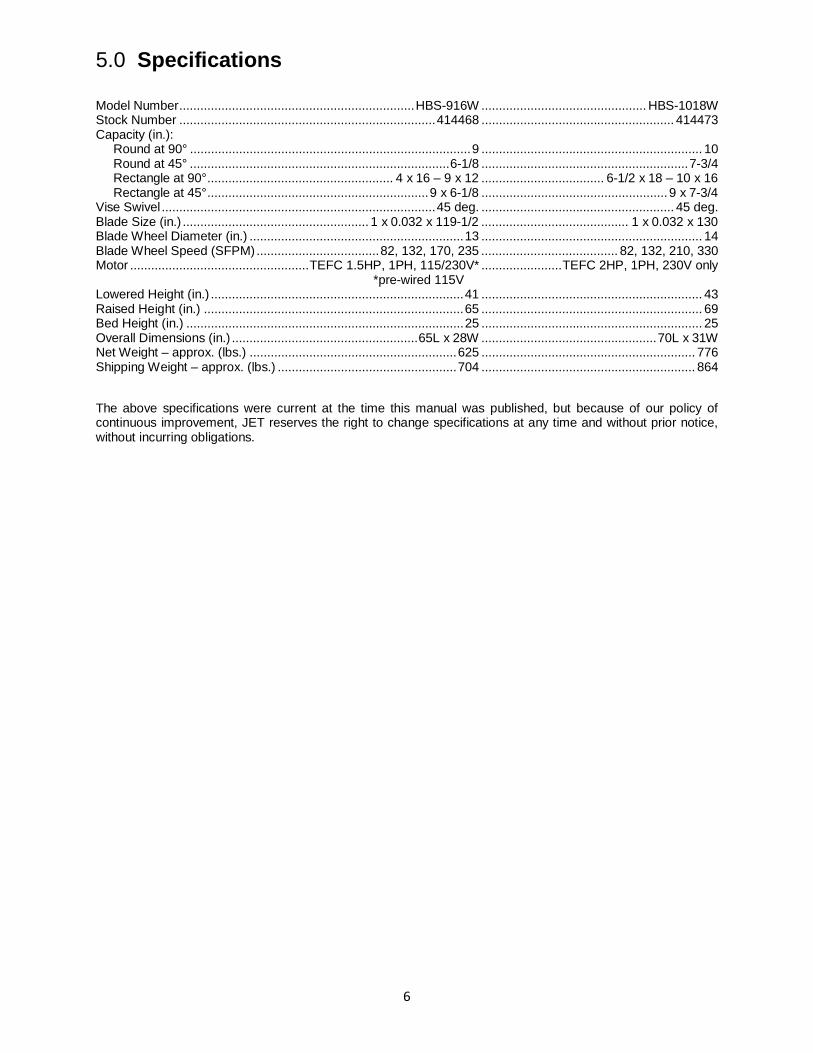
5.0 Specifications Model Number ................................................................... HBS-916W ............................................... HBS-1018W Stock Number ......................................................................... 414468 ....................................................... 414473 Capacity (in.): Round at 90° ................................................................................ 9 ............................................................... 10 Round at 45° .......................................................................... 6-1/8 ........................................................... 7-3/4 Rectangle at 90° ..................................................... 4 x 16 – 9 x 12 ................................... 6-1/2 x 18 – 10 x 16 Rectangle at 45° ............................................................... 9 x 6-1/8 ..................................................... 9 x 7-3/4 Vise Swivel .............................................................................. 45 deg. ....................................................... 45 deg. Blade Size (in.) ..................................................... 1 x 0.032 x 119-1/2 .......................................... 1 x 0.032 x 130 Blade Wheel Diameter (in.) ............................................................. 13 ............................................................... 14 Blade Wheel Speed (SFPM) ................................... 82, 132, 170, 235 ....................................... 82, 132, 210, 330 Motor ................................................... TEFC 1.5HP, 1PH, 115/230V* ....................... TEFC 2HP, 1PH, 230V only *pre-wired 115V Lowered Height (in.) ........................................................................ 41 ............................................................... 43 Raised Height (in.) .......................................................................... 65 ............................................................... 69 Bed Height (in.) ............................................................................... 25 ............................................................... 25 Overall Dimensions (in.) ..................................................... 65L x 28W .................................................. 70L x 31W Net Weight – approx. (lbs.) ........................................................... 625 ............................................................. 776 Shipping Weight – approx. (lbs.) ................................................... 704 ............................................................. 864
The above specifications were current at the time this manual was published, but because of our policy of continuous improvement, JET reserves the right to change specifications at any time and without prior notice, without incurring obligations.

7
6.0 Uncrating and cleanup Note: Read and understand the entire manual before attempting setup or operation.
1. Finish uncrating the saw and inspect for damage. Should any have occurred, contact your local distributor.
2. Remove all bolts attaching machine to shipping base.
3. Leave packing material between vise clamps and saw head intact until band saw has been lifted to its final position.
4. Clean all rust protected surfaces with kerosene or diesel oil to remove protective coating. Do not use gasoline, paint thinner, mineral spirits, etc. These may damage painted surfaces.
5. Lubricate all slideways with SAE 10W oil.
7.0 Installation For best performance, the band saw should be located on a solid and level foundation. Allow room for servicing and for moving large stock around the band saw when deciding a location for the machine.
1. Using lifting straps that are isolated from the band saw’s finished surfaces, lift machine and place in desired location. See Figure 1 for strap placement.
2. Install four leveling bolts with lock nuts on both sides of the base as shown in the parts breakdown, sect. 14.1.1, items 2 and 3.
3. Place a level on the table surface and check side-to-side and front-to-back.
4. Adjust leveling screws until machine is level in both directions and tighten locking nuts.
Figure 1
8.0 Assembly 1. Unbolt the motor assembly from the shipping
crate bottom.
2. Remove nut and washer from the motor support shaft.
3. Remove shaft (A, Figure 2) from the motor mount bracket.
Figure 2
4. Carefully lift motor and line up holes in the motor mounting plate and the motor bracket.
5. Slide motor support shaft into motor mount bracket to hold the motor in place.
6. Fasten shaft with nut and washer.
7. Loosen strain relief nut on the motor junction box. Remove the junction box cover. Insert wire through strain relief and connect to the terminal strip using the diagram on the junction box cover. Tighten the strain relief nut and replace the junction box cover.
8. Remove two hex cap bolts and washers (A, Figure 3) from the right side of the saw arm.
9. Slide belt cover (B, Figure 3) around pulley shafts and attach to saw with two hex cap bolts and two washers.
Figure 3
10. Lift motor and place v-belt around both pulleys. Lower motor.

8
11. Tension the v-belt by pushing down on the motor and tightening the lock handle on the motor tilt plate. Correct tension is achieved when finger pressure between the two pulleys causes approximately a 1/2” deflection. See Figure 4.
Figure 4
12. Close pulley cover door and fasten with lock knob.
13. Fasten work stop rod (#17, sect. 14.1.1) to saw bed (#11) by inserting into bed and turning clockwise until tight. Place work stop bracket (#16) onto stop rod (#17) and tighten lock handle (#20). Attach stop screw (#19) to stop bracket (#16) with lock handle (#18) and tighten.
9.0 Electrical connections
Electrical connections must be made by a qualified electrician in compliance with all relevant codes. This machine must be properly grounded to help prevent electrical shock and possible fatal injury.
Disconnect machine from power source before changing any voltage components!
The HBS-916W Band Saw is rated at 115/230V single phase, and is pre-wired 115 volt from the factory. The HBS-1018W is rated at 230V only, single phase. Confirm that power available at the saw’s location matches that for which the saw is wired.
To convert the HBS-916W from 115V to 230V, the following items will have to be changed:
Main Motor – follow diagram inside junction box cover.
Coolant Pump – Remove chip pan on front of saw, remove junction box cover on pump, and follow diagram inside junction box cover.
Control Transformer – Open electrical panel on rear of base and change the fuse from 115V to 230V.
Machine must always be correctly grounded.
NOTE: The power cord end will have to be changed to one rated 230V when changing to the higher voltage.
10.0 Controls Refer to Figure 5.
Figure 5
Power Indicator Light (A) – lit whenever machine is running.
Start Button (B) – press to start band saw.
Emergency Stop Button (C) – press to immediately stop all machine functions.
Coolant Switch (D) – Turn arrow to “I” to turn on coolant flow. Turn arrow to “O” to stop coolant flow.
Cutting Pressure Control (E) – turn clockwise to decrease cutting pressure. Turn counter-clockwise to increase cutting pressure.
Hydraulic On-Off Valve (F) – turns hydraulic cylinder on and off.
11.0 Prior to Operation 1. Check that blade tooth direction matches
diagram on blade guides.
2. Check to see that blade is properly seated on wheels after applying correct tension (approximately 25,000 lbs.).
3. Set blade holder guides for approximately .003” to .005” clearance between guides and blade.
4. Check for slight clearance between back up rollers and back of blade.
5. Position blade guides as close to workpiece as possible.
6. Select proper speed and feed rate for material being cut. See speed selection chart found in the enclosed “Guide to Band Sawing” booklet supplied with this saw.
7. Material to be cut must be securely held in vise.
9
8. Check to see that coolant level is adequate and turn on coolant pump if material to be cut requires it. Machine should be filled with four gallons of the proper coolant mixture. Follow the directions on the product maker’s label and fill the coolant tank through the chip tray area.
9. Do not start cut on a sharp edge.
10. Keep machine lubricated. See “Lubrication” section.
12.0 Adjustments
12.1 Adjusting vise square to blade 1. Disconnect the machine from the power
source.
2. Place a machinist’s square on the table against the blade and the vise. The square should lie along the entire length of the vise and blade without a gap.
3. If adjustment is necessary, loosen bolts holding the vise and adjust vise so square lines up properly. Tighten bolts.
4. Connect machine to the power source.
12.2 Changing blade speeds
Disconnect machine from the power source before changing blade speeds. Failure to comply may cause serious injury.
1. Disconnect machine from the power source.
2. Open pulley cover by supporting the belt cover with one hand while removing the belt cover lock knob with the other. Lower guard gently to its full open position.
3. Support motor with one hand while loosening lock handle (A, Figure 6). Lower motor gently.
Figure 6
4. Position belt in grooves according to the speed selection chart.
5. Tension the v-belt by pushing down on the motor and tightening the lock handle on the motor tilt plate. Correct tension is achieved
when finger pressure on the belt between the two pulleys causes approximately a 1/2" deflection.
6. Close pulley cover and fasten.
7. Connect machine to the power source.
12.3 Adjusting feed rate Rate of feed is adjusted by turning the cutting pressure control knob on the control panel. Rate of feed is important to band saw performance; excessive pressure may break the blade or stall the saw. Insufficient pressure rapidly dulls the blade.
Material chips or shavings are the best indicator of proper speed and pressure. The ideal chip is thin, tightly curled, and warm to the touch. Chips that range from golden brown to black indicate excessive force. Blue chips indicate extreme heat from too high a band speed which will shorten blade life. Thin or powdered chips indicate insufficient feed pressure.
Consult a Machinery’s Handbook or similar source for speed and feed rate charts.
12.4 Changing blades
Disconnect machine from power source before making any adjustments or repairs. Failure to comply may result in serious injury.
1. Disconnect machine from power source.
2. Raise saw arm approximately 6 inches. Hold saw arm in place by closing cutting pressure control valve. Remove screw (#145, sect. 14.1.2 and sect 14.1.3), washer (#146), and brush (#147) from the wire brush post (#148).
3. Open both wheel covers and clean chips out of both wheel housings. Loosen two lock knobs and remove upper blade guard.
4. Release blade tension by turning blade tensioning handwheel (A, Figure 7) counter-clockwise until blade is free.
Figure 7
10
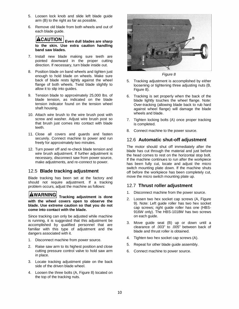
5. Loosen lock knob and slide left blade guide arm (B) to the right as far as possible.
6. Remove old blade from both wheels and out of each blade guide.
Even dull blades are sharp to the skin. Use extra caution handling band saw blades.
7. Install new blade making sure teeth are pointed downward in the proper cutting direction. If necessary, turn blade inside out.
8. Position blade on band wheels and tighten just enough to hold blade on wheels. Make sure back of blade rests lightly against the wheel flange of both wheels. Twist blade slightly to allow it to slip into guides.
9. Tension blade to approximately 25,000 lbs. of blade tension, as indicated on the blade tension indicator found on the tension wheel shaft housing.
10. Attach wire brush to the wire brush post with screw and washer. Adjust wire brush post so that brush just comes into contact with blade teeth.
11. Close all covers and guards and fasten securely. Connect machine to power and run freely for approximately two minutes.
12. Turn power off and re-check blade tension and wire brush adjustment. If further adjustment is necessary, disconnect saw from power source, make adjustments, and re-connect to power.
12.5 Blade tracking adjustment Blade tracking has been set at the factory and should not require adjustment. If a tracking problem occurs, adjust the machine as follows:
Tracking adjustment is done with the wheel covers open to observe the blade. Use extreme caution so that you do not come into contact with the blade.
Since tracking can only be adjusted while machine is running, it is suggested that this adjustment be accomplished by qualified personnel that are familiar with this type of adjustment and the dangers associated with it.
1. Disconnect machine from power source.
2. Raise saw arm to its highest position and close cutting pressure control valve to hold saw arm in place.
3. Locate tracking adjustment plate on the back side of the driven blade wheel.
4. Loosen the three bolts (A, Figure 8) located on the top of the tracking nuts.
Figure 8
5. Tracking adjustment is accomplished by either loosening or tightening three adjusting nuts (B, Figure 8).
6. Tracking is set properly when the back of the blade lightly touches the wheel flange. Note: Over-tracking (allowing blade back to rub hard against wheel flange) will damage the blade wheels and blade.
7. Tighten locking bolts (A) once proper tracking is completed.
8. Connect machine to the power source.
12.6 Automatic shut-off adjustment The motor should shut off immediately after the blade has cut through the material and just before the head comes to rest on the horizontal stop bolt. If the machine continues to run after the workpiece has been fully cut, locate and adjust the micro switch mounting plate down. If the machine shuts off before the workpiece has been completely cut, move the micro switch mounting plate up.
12.7 Thrust roller adjustment 1. Disconnect machine from the power source.
2. Loosen two hex socket cap screws (A, Figure 9). Note: Left guide roller has two hex socket cap screws; right guide roller has one (HBS-916W only). The HBS-1018W has two screws on each guide.
3. Move guide seat (B) up or down until a clearance of .003” to .005” between back of blade and thrust roller is obtained.
4. Tighten two hex socket cap screws (A).
5. Repeat for other blade guide assembly.
6. Connect machine to power source.
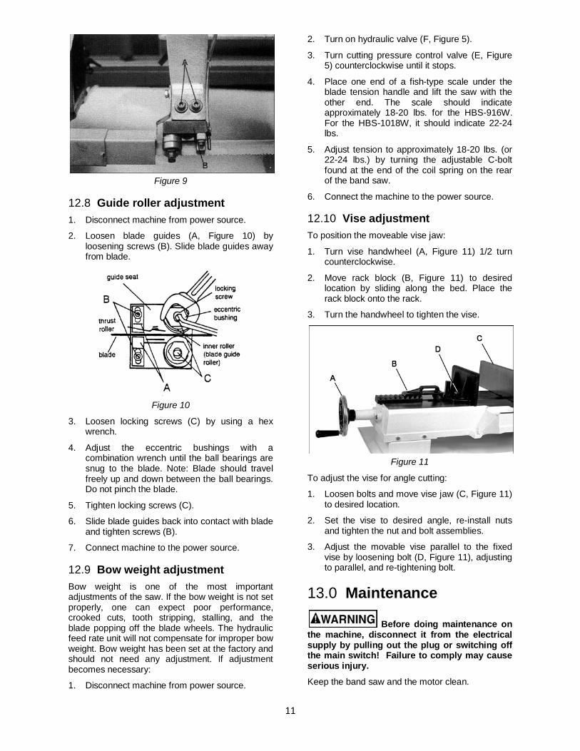
11
Figure 9
12.8 Guide roller adjustment 1. Disconnect machine from power source.
2. Loosen blade guides (A, Figure 10) by loosening screws (B). Slide blade guides away from blade.
Figure 10
3. Loosen locking screws (C) by using a hex wrench.
4. Adjust the eccentric bushings with a combination wrench until the ball bearings are snug to the blade. Note: Blade should travel freely up and down between the ball bearings. Do not pinch the blade.
5. Tighten locking screws (C).
6. Slide blade guides back into contact with blade and tighten screws (B).
7. Connect machine to the power source.
12.9 Bow weight adjustment Bow weight is one of the most important adjustments of the saw. If the bow weight is not set properly, one can expect poor performance, crooked cuts, tooth stripping, stalling, and the blade popping off the blade wheels. The hydraulic feed rate unit will not compensate for improper bow weight. Bow weight has been set at the factory and should not need any adjustment. If adjustment becomes necessary:
1. Disconnect machine from power source.
2. Turn on hydraulic valve (F, Figure 5).
3. Turn cutting pressure control valve (E, Figure 5) counterclockwise until it stops.
4. Place one end of a fish-type scale under the blade tension handle and lift the saw with the other end. The scale should indicate approximately 18-20 lbs. for the HBS-916W. For the HBS-1018W, it should indicate 22-24 lbs.
5. Adjust tension to approximately 18-20 lbs. (or 22-24 lbs.) by turning the adjustable C-bolt found at the end of the coil spring on the rear of the band saw.
6. Connect the machine to the power source.
12.10 Vise adjustment To position the moveable vise jaw:
1. Turn vise handwheel (A, Figure 11) 1/2 turn counterclockwise.
2. Move rack block (B, Figure 11) to desired location by sliding along the bed. Place the rack block onto the rack.
3. Turn the handwheel to tighten the vise.
Figure 11
To adjust the vise for angle cutting:
1. Loosen bolts and move vise jaw (C, Figure 11) to desired location.
2. Set the vise to desired angle, re-install nuts and tighten the nut and bolt assemblies.
3. Adjust the movable vise parallel to the fixed vise by loosening bolt (D, Figure 11), adjusting to parallel, and re-tightening bolt.
13.0 Maintenance
Before doing maintenance on the machine, disconnect it from the electrical supply by pulling out the plug or switching off the main switch! Failure to comply may cause serious injury.
Keep the band saw and the motor clean.
12
If the power cord is worn, cut, or damaged in any way, have it replaced immediately.
13.1 Lubrication All ball bearings are permanently lubricated and sealed. They require no further attention.
The gear box lubricant should be changed after the first 50 hours of operation. Change lubricant from then on every 250 hours of operation.
To check level of gear box lubricant, place saw arm in down position and allow a few minutes to pass so that oil drains down. Check level in sight glass on side of gear casing. Correct level is the dot in the middle of sight glass.
To change gear box lubricant:
1. Disconnect machine from the power source.
2. Open drain plug and allow lubricant to drain completely. Drain plug may be found on lower front of gear case under right wheel cover. Remove drain plug with a hex wrench.
3. Replace drain plug.
4. Remove filler cap (A, Figure 12) and fill gear box with Mobil DTE® Oil Heavy Medium until level reaches dot in middle of sight glass.
5. Replace filler cap.
6. Connect machine to the power source.
Use a light machine oil to lubricate all other moving parts as needed.
Figure 12
14.0 Replacement Parts Replacement parts are listed on the following pages. To order parts or reach our service department, call 1-800-274-6848 Monday through Friday, 8:00 a.m. to 5:00 p.m. CST. Having the Model Number and Serial Number of your machine available when you call will allow us to serve you quickly and accurately.
13
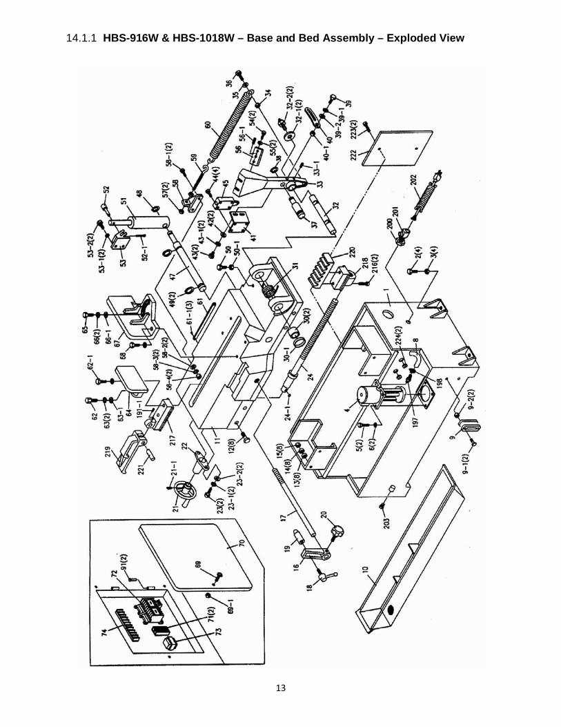
14.1.1 HBS-916W & HBS-1018W – Base and Bed Assembly – Exploded View

14
14.1.2 HBS-916W only – Saw Arm Assembly – Exploded View
15
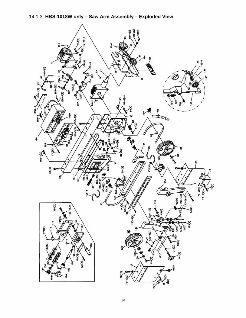
14.1.3 HBS-1018W only – Saw Arm Assembly – Exploded View

16
14.1.4 Parts List for HBS-916W, HBS-1018W
Index No. Part No. Description Size Qty 1 ................ HBS916W-01 ............ Base (S/N 8081108 and lower)................................ ...................................... 1 .................. HBS916W-01AG ....... Base (S/N 8081109 and higher) .............................. ...................................... 1 .................. HBS1018W-01 .......... Base (S/N 808718 and lower).................................. ...................................... 1 .................. HBS1018W-01AG ..... Base (S/N 808719 and higher) ................................ ...................................... 1 2 ................ TS-1492071 .............. Hex Cap Bolt............................................................ M12x70 ......................... 4 3 ................ TS-1540081 .............. Hex Nut .................................................................... M12 ............................... 4 4 ................ HBS916W-CP ........... Coolant Pump .......................................................... ...................................... 1 5 ................ TS-1531051 .............. Pan Head Screw ...................................................... M6x16 ........................... 2 6 ................ TS-1551061 .............. Lock Washer ............................................................ M6 ................................. 2 8 ................ HBS916W-08 ............ Hose ........................................................................ ...................................... 1 9 ................ HBS916W-09 ............ Coolant Gauge......................................................... ...................................... 1 9-1 ............. TS-1491041 .............. Hex Cap Bolt............................................................ M10X30......................... 2 9-2 ............. TS-1540071 .............. Hex Nut .................................................................... M10 ............................... 2 10 .............. HBS916W-10G ......... Chip Tray ................................................................. ...................................... 1 .................. HBS1018W-10G ....... Chip Tray ................................................................. ...................................... 1 11 .............. HBS916W-11 ............ Bed (S/N 8081108 and lower) ................................. ...................................... 1 .................. HBS916W-11AG ....... Bed (S/N 8081109 and higher) ................................ ...................................... 1 .................. HBS1018W-11 .......... Bed (S/N 808718 and lower) ................................... ...................................... 1 .................. HBS1018W-11AG ..... Bed (S/N 808719 and higher) .................................. ...................................... 1 12 .............. TS-1490051 .............. Hex Cap Bolt............................................................ M8x30 ........................... 8 13 .............. TS-1550061 .............. Washer .................................................................... 8mm .............................. 8 14 .............. TS-1551081 .............. Lock Washer ............................................................ 8mm .............................. 8 15 .............. TS-1540061 .............. Hex Nut .................................................................... M8 ................................. 8 16 .............. HBS916W-16 ............ Stop Bracket ............................................................ ...................................... 1 17 .............. HBS916W-17 ............ Stop Rod .................................................................. ...................................... 1 18 .............. HBS916W-18 ............ Lock Handle ............................................................. ...................................... 1 19 .............. HBS916W-19 ............ Work Stop ................................................................ ...................................... 1 20 .............. HBS916W-20 ............ Lock Knob ................................................................ ...................................... 1 21 .............. HBS916W-21 ............ Hand Wheel Assembly ............................................ ...................................... 1 .................. HBS1018W-21 .......... Hand Wheel Assembly ............................................ ...................................... 1 21 .............. HBS916W-21-1 ......... Set Screw ................................................................ 5/16” x 8” ....................... 1 22 .............. HBS916W-22G ......... Lead Screw Seat ..................................................... ...................................... 1 .................. HBS1018W-22G ....... Lead Screw Seat ..................................................... ...................................... 1 23 .............. TS-1490051 .............. Hex Cap Bolt............................................................ M8x30 ........................... 2 23-1 ........... TS-1551061 .............. Lock Washer ............................................................ 8mm .............................. 2 23-2 ........... TS-1550061 .............. Washer .................................................................... 8mm .............................. 2 24 .............. HBS916W-24 ............ Lead Screw (S/N 8081108 and lower) ..................... ...................................... 1 .................. HBS916W-24A .......... Lead Screw (S/N 8081109 and higher) ................... ...................................... 1 .................. HBS1018W-24 .......... Lead Screw (S/N 808718 and lower) ....................... ...................................... 1 .................. HBS1018W-24A ........ Lead Screw (S/N 808719 and higher) ..................... ...................................... 1 24-1 ........... HBS916W-24-1 ......... Key........................................................................... 5x5x20mm .................... 1 30 .............. HK-2516-2RS ............ Needle Bearing ........................................................ ...................................... 2 30-1 ........... HBS916-30-1 ............ Bushing .................................................................... ...................................... 1 31 .............. HBS916W-31 ............ Torsion Spring ......................................................... ...................................... 1 .................. HBS1018W-31 .......... Torsion Spring ......................................................... ...................................... 1 32 .............. HBS916W-32 ............ Pivot Shaft ............................................................... ...................................... 1 32-1 ........... TS-1550041 .............. Washer .................................................................... 12mm ............................ 2 32-2 ........... HBS916W-32-2 ......... Bolt w/ Zerk Fitting ................................................... ...................................... 2 33 .............. HBS916W-33G ......... Pivot Bracket............................................................ ...................................... 1 .................. HBS1018W-33G ....... Pivot Bracket............................................................ ...................................... 1 33-1 ........... TS-1525021 .............. Set Screw ................................................................ M10x12 ......................... 1 34 .............. TS-1540081 .............. Nut ........................................................................... M12 ............................... 1 35 .............. TS-1550081 .............. Washer .................................................................... 12mm ............................ 1 36 .............. TS-1492041 .............. Hex Cap Bolt............................................................ M12x40 ......................... 1 37 .............. HBS916W-37 ............ Torsion Spring Shaft ................................................ ...................................... 1 38 .............. HBS916W-38 ............ C-Ring...................................................................... S-22 .............................. 1 39 .............. TS-1490041 .............. Hex Cap Bolt............................................................ M8x25 ........................... 1 39-1 ........... TS-1551081 .............. Lock Washer ............................................................ 8mm .............................. 1
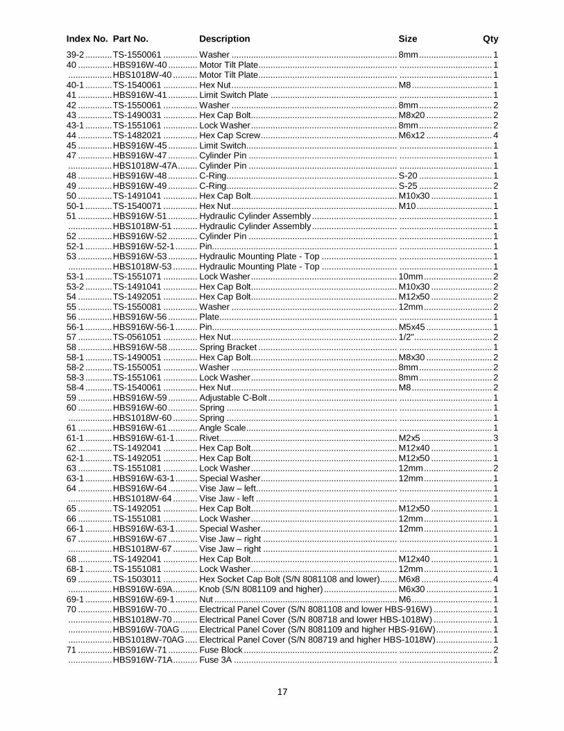
17
Index No. Part No. Description Size Qty 39-2 ........... TS-1550061 .............. Washer .................................................................... 8mm .............................. 1 40 .............. HBS916W-40 ............ Motor Tilt Plate......................................................... ...................................... 1 .................. HBS1018W-40 .......... Motor Tilt Plate......................................................... ...................................... 1 40-1 ........... TS-1540061 .............. Hex Nut .................................................................... M8 ................................. 1 41 .............. HBS916W-41 ............ Limit Switch Plate .................................................... ...................................... 1 42 .............. TS-1550061 .............. Washer .................................................................... 8mm .............................. 2 43 .............. TS-1490031 .............. Hex Cap Bolt............................................................ M8x20 ........................... 2 43-1 ........... TS-1551061 .............. Lock Washer ............................................................ 8mm .............................. 2 44 .............. TS-1482021 .............. Hex Cap Screw ........................................................ M6x12 ........................... 4 45 .............. HBS916W-45 ............ Limit Switch.............................................................. ...................................... 1 47 .............. HBS916W-47 ............ Cylinder Pin ............................................................. ...................................... 1 .................. HBS1018W-47A ........ Cylinder Pin ............................................................. ...................................... 1 48 .............. HBS916W-48 ............ C-Ring...................................................................... S-20 .............................. 1 49 .............. HBS916W-49 ............ C-Ring...................................................................... S-25 .............................. 2 50 .............. TS-1491041 .............. Hex Cap Bolt............................................................ M10x30 ......................... 1 50-1 ........... TS-1540071 .............. Hex Nut .................................................................... M10 ............................... 1 51 .............. HBS916W-51 ............ Hydraulic Cylinder Assembly ................................... ...................................... 1 .................. HBS1018W-51 .......... Hydraulic Cylinder Assembly ................................... ...................................... 1 52 .............. HBS916W-52 ............ Cylinder Pin ............................................................. ...................................... 1 52-1 ........... HBS916W-52-1 ......... Pin............................................................................ ...................................... 1 53 .............. HBS916W-53 ............ Hydraulic Mounting Plate - Top ............................... ...................................... 1 .................. HBS1018W-53 .......... Hydraulic Mounting Plate - Top ............................... ...................................... 1 53-1 ........... TS-1551071 .............. Lock Washer ............................................................ 10mm ............................ 2 53-2 ........... TS-1491041 .............. Hex Cap Bolt............................................................ M10x30 ......................... 2 54 .............. TS-1492051 .............. Hex Cap Bolt............................................................ M12x50 ......................... 2 55 .............. TS-1550081 .............. Washer .................................................................... 12mm ............................ 2 56 .............. HBS916W-56 ............ Plate......................................................................... ...................................... 1 56-1 ........... HBS916W-56-1 ......... Pin............................................................................ M5x45 ........................... 1 57 .............. TS-0561051 .............. Hex Nut .................................................................... 1/2" ................................ 2 58 .............. HBS916W-58 ............ Spring Bracket ......................................................... ...................................... 1 58-1 ........... TS-1490051 .............. Hex Cap Bolt............................................................ M8x30 ........................... 2 58-2 ........... TS-1550051 .............. Washer .................................................................... 8mm .............................. 2 58-3 ........... TS-1551061 .............. Lock Washer ............................................................ 8mm .............................. 2 58-4 ........... TS-1540061 .............. Hex Nut .................................................................... M8 ................................. 2 59 .............. HBS916W-59 ............ Adjustable C-Bolt ..................................................... ...................................... 1 60 .............. HBS916W-60 ............ Spring ...................................................................... ...................................... 1 .................. HBS1018W-60 .......... Spring ...................................................................... ...................................... 1 61 .............. HBS916W-61 ............ Angle Scale.............................................................. ...................................... 1 61-1 ........... HBS916W-61-1 ......... Rivet......................................................................... M2x5 ............................. 3 62 .............. TS-1492041 .............. Hex Cap Bolt............................................................ M12x40 ......................... 1 62-1 ........... TS-1492051 .............. Hex Cap Bolt............................................................ M12x50 ......................... 1 63 .............. TS-1551081 .............. Lock Washer ............................................................ 12mm ............................ 2 63-1 ........... HBS916W-63-1 ......... Special Washer........................................................ 12mm ............................ 1 64 .............. HBS916W-64 ............ Vise Jaw – left.......................................................... ...................................... 1 .................. HBS1018W-64 .......... Vise Jaw - left .......................................................... ...................................... 1 65 .............. TS-1492051 .............. Hex Cap Bolt............................................................ M12x50 ......................... 1 66 .............. TS-1551081 .............. Lock Washer ............................................................ 12mm ............................ 1 66-1 ........... HBS916W-63-1 ......... Special Washer........................................................ 12mm ............................ 1 67 .............. HBS916W-67 ............ Vise Jaw – right ....................................................... ...................................... 1 .................. HBS1018W-67 .......... Vise Jaw – right ....................................................... ...................................... 1 68 .............. TS-1492041 .............. Hex Cap Bolt............................................................ M12x40 ......................... 1 68-1 ........... TS-1551081 .............. Lock Washer ............................................................ 12mm ............................ 1 69 .............. TS-1503011 .............. Hex Socket Cap Bolt (S/N 8081108 and lower)....... M6x8 ............................. 4 .................. HBS916W-69A .......... Knob (S/N 8081109 and higher) .............................. M6x30 ........................... 1 69-1 ........... HBS916W-69-1 ......... Nut ........................................................................... M6 ................................. 1 70 .............. HBS916W-70 ............ Electrical Panel Cover (S/N 8081108 and lower HBS-916W) ........................ 1 .................. HBS1018W-70 .......... Electrical Panel Cover (S/N 808718 and lower HBS-1018W) ........................ 1 .................. HBS916W-70AG ....... Electrical Panel Cover (S/N 8081109 and higher HBS-916W) ....................... 1 .................. HBS1018W-70AG ..... Electrical Panel Cover (S/N 808719 and higher HBS-1018W) ....................... 1 71 .............. HBS916W-71 ............ Fuse Block ............................................................... ...................................... 2 .................. HBS916W-71A .......... Fuse 3A ................................................................... ...................................... 1

18
Index No. Part No. Description Size Qty 72 .............. HBS916W-72B .......... Magnetic Switch....................................................... ...................................... 1 .................. HBS1018W-72 .......... Magnetic Switch....................................................... ...................................... 1 .................. HBS916W-72-1 ......... Contactor (main motor) ............................................ ...................................... 1 .................. HBS916W-72A-1....... Overload Relay ........................................................ ...................................... 1 .................. HBS916W-72A-2....... Contactor (pump) ..................................................... ...................................... 1 73 .............. HBS916W-73A .......... Transformer ............................................................. ...................................... 1 .................. HBS1018W-73 .......... Transformer ............................................................. ...................................... 1 74 .............. HBS916W-74 ............ Terminal Strip .......................................................... ...................................... 1 75 .............. HBS916W-75 ............ Handle ..................................................................... ...................................... 2 76 .............. TS-1534051 .............. Pan Head Screw ...................................................... M6x16 ........................... 4 77 .............. TS-1482021 .............. Hex Cap Bolt............................................................ M6x12 ........................... 2 77-1 ........... TS-1551041 .............. Lock Washer ............................................................ M6 ................................. 2 77-2 ........... TS-1550041 .............. Washer .................................................................... M6 ................................. 2 78 .............. HBS916W-78 ............ Wire Brush Guard .................................................... ...................................... 1 79 .............. TS-1503011 .............. Hex Socket Cap Screw ............................................ M6x8 ........................... 12 .................. HBS1018W-79A ........ Adjustable Bracket Mount - rear (HBS-1018W only; not shown) .................... 1 79-1 ........... TS-1550051 .............. Washer (HBS-1018 only) ......................................... M6 ............................... 12 80 .............. HBS916W-80G ......... Blade Wheel Cover - right........................................ ...................................... 1 .................. HBS1018W-80AG ..... Blade Wheel Cover - right........................................ ...................................... 1 81 .............. TS-1550041 .............. Washer .................................................................... M6 ................................. 4 82 .............. HBS916W-82 ............ Bushing .................................................................... ...................................... 1 83 .............. HBS916W-83 ............ Washer .................................................................... ...................................... 1 84 .............. HBS916W-84 ............ Drive Wheel ............................................................. ...................................... 1 .................. HBS1018W-84A ........ Drive Wheel ............................................................. 14” ................................. 1 85 .............. .................................. Blade (local purchase, HBS-916W) ......................... ...................................... 1 .................. .................................. Blade (local purchase, HBS-1018W) ....................... ...................................... 1 86 .............. HBS916W-86 ............ Hose ........................................................................ ...................................... 1 87 .............. TS-1533031 .............. Pan Head Screw ...................................................... M5x10 ........................... 2 88 .............. HBS916W-88 ............ Filter Screen ............................................................ ...................................... 1 89 .............. TS-1492031 .............. Hex Cap Bolt............................................................ M12x35 ......................... 4 89-1 ........... TS-1551081 .............. Lock Washer ............................................................ M12 ............................... 4 90 .............. HBS916W-90 ............ Lock Knob ................................................................ ...................................... 4 91 .............. HBS916W-91 ............ Hinge Pin ................................................................. ...................................... 2 92 .............. HBS916W-92G ......... Blade Wheel Box - right ........................................... ...................................... 1 .................. HBS1018W-92G ....... Blade Wheel Box - right ........................................... ...................................... 1 92-1 ........... TS-1525021 .............. Set Screw ................................................................ M10x12 ......................... 2 93 .............. HBS916W-93 ............ Connector ................................................................ ...................................... 1 .................. HBS1018W-93 .......... Connector ................................................................ ...................................... 1 94 .............. HBS916W-94G ......... Gear Box Assembly (can only order entire assembly).................................... 1 .................. HBS1018W-94G ....... Gear Box Assembly (can only order entire assembly).................................... 1 94-1 ........... HBS916W-94-1 ......... Key........................................................................... 7x7x45MM .................... 1 95 .............. HBS916W-95 ............ Key........................................................................... 7MM .............................. 1 96 .............. HBS916W-96 ............ Pulley Cover ............................................................ ...................................... 1 .................. HBS1018W-96 .......... Pulley Cover ............................................................ ...................................... 1 96-1 ........... HBS916W-96-1 ......... Lock Knob ................................................................ ...................................... 1 97 .............. HBS916W-97 ............ Gear Box Pulley ....................................................... ...................................... 1 .................. HBS1018W-97 .......... Gear Box Pulley ....................................................... ...................................... 1 98 .............. VB-A39 ...................... V-Belt (for HBS-916W) ............................................ ...................................... 1 .................. VB-A37 ...................... V-Belt (for HBS-1018W) .......................................... ...................................... 1 99 .............. HBS916W-99 ............ Motor Pulley ............................................................. ...................................... 1 .................. HBS1018W-99 .......... Motor Pulley ............................................................. ...................................... 1 99-1 ........... TS-1524021 .............. Set Screw ................................................................ M8x10 ........................... 2 100 ............ TS-1482031 .............. Hex Cap Bolt............................................................ M8x16 ........................... 2 100-1 ......... TS-1550061 .............. Washer .................................................................... M8 ................................. 2 100-2 ......... TS-1551061 .............. Lock Washer ............................................................ M8 ................................. 2 101 ............ HBS916W-101 .......... Hose ........................................................................ ...................................... 1 101-1 ......... HBS916W-101-1 ....... Hose ........................................................................ ...................................... 1 102 ............ HBS916W-102 .......... Support Shaft ........................................................... ...................................... 1 102-1 ......... TS-1550081 .............. Washer .................................................................... M12 ............................... 1 102-2 ......... TS-1540081 .............. Hex Nut .................................................................... M12 ............................... 1 102-3 ......... HBS916W-102-3 ....... C-Ring...................................................................... S-19 .............................. 1

19
Index No. Part No. Description Size Qty 103 ............ TS-1492021 .............. Hex Cap Bolt............................................................ M12x30 ......................... 2 103-1 ......... HBS916W-103-1 ....... Hex Cap Bolt............................................................ M12x20 ......................... 2 104 ............ HBS916W-104 .......... Motor Mount Bracket ............................................... ...................................... 1 105 ............ HBS916W-105G ....... Column .................................................................... ...................................... 1 .................. HBS1018W-105 ........ Column (S/N 606105 and lower) ............................. ...................................... 1 .................. HBS1018W-105AG ... Column (S/N 606106 and higher) ............................ ...................................... 1 106 ............ TS-1506011 .............. Hex Socket Cap Screw ............................................ M12x20 ......................... 6 106-1 ......... TS-1551081 .............. Lock Washer ............................................................ M12 ............................... 1 106-2 ......... TS-1540081 .............. Washer .................................................................... M12 ............................... 1 107 ............ HBS916W-107 .......... Locking Handle ........................................................ ...................................... 1 108 ............ TS-1550061 .............. Washer .................................................................... 8MM .............................. 1 108-1 ......... TS-1551061 .............. Lock Washer ............................................................ M8 ................................. 1 109 ............ TS-1490081 .............. Hex Cap Bolt............................................................ M8x45 ........................... 4 109-1 ......... TS-1550061 .............. Washer .................................................................... M8 ................................. 4 110 ............ HBS916W-110 .......... Motor Mount Plate ................................................... ...................................... 1 111 ............ HBS916W-111 .......... Motor.................................................1-1/2 HP, 1PH, 115/230V ..................... 1 .................. HBS1018W-111 ........ Motor.................................................2 HP, 1PH, 230V only........................... 1 .................. C-400125 .................. Capacitor (not shown).............................................. 400MFD, 125VAC ......... 1 .................. HBS916W-111-2 ....... Capacitor Cover (not shown) ................................... ...................................... 1 .................. HBS1018W-111-1 ..... Capacitor (not shown).............................................. 400MFD, 125VAC ......... 1 .................. HBS1018W-111-2 ..... Capacitor Cover (not shown) ................................... ...................................... 1 112 ............ TS-1550061 .............. Washer .................................................................... M8 ................................. 4 112-1 ......... TS-1551061 .............. Lock Washer ............................................................ M8 ................................. 4 113 ............ TS-1540061 .............. Hex Nut .................................................................... M8 ................................. 4 114 ............ HBS916W-114 .......... Key........................................................................... 7MM .............................. 1 115 ............ TS-1550081 .............. Washer .................................................................... M12 ............................... 1 116 ............ TS-1504041 .............. Hex Socket Cap Screw ............................................ M8x20 ........................... 1 116-1 ......... HBS916W-116-1 ....... Shaft (HBS-916W) ................................................... ...................................... 1 117 ............ HBS916W-117G ....... Blade Wheel Cover - left .......................................... ...................................... 1 .................. HBS1018W-117AG ... Blade Wheel Cover - left .......................................... ...................................... 1 118 ............ BB-608VV ................. Ball Bearing ............................................................. ...................................... 2 119 ............ TS-1492011 .............. Hex Cap Bolt............................................................ M12x25 ......................... 2 120 ............ TS-1550081 .............. Washer .................................................................... M12 ............................... 1 121 ............ BB-6205Z .................. Ball Bearing ............................................................. ...................................... 3 122 ............ HBS916W-122 .......... Idler Wheel............................................................... ...................................... 1 .................. HBS1018W-122 ........ Idler Wheel............................................................... ...................................... 1 123 ............ HBS916W-123 .......... Blade Guard............................................................. ...................................... 1 .................. HBS1018W-123 ........ Blade Guard (S/N 606105 and lower)...................... ...................................... 1 .................. HBS1018W-123A ...... Blade Guard (S/N 606106 and higher) .................... ...................................... 1 123-1 ......... TS-1550061 .............. Washer .................................................................... M8 ................................. 2 123-2 ......... TS-1551061 .............. Lock Washer ............................................................ M8 ................................. 1 123-3 ......... TS-1490021 .............. Hex Cap Bolt............................................................ M8x16 ........................... 1 124 ............ HBS916W-124 .......... Guide Bracket - left .................................................. ...................................... 1 .................. HBS916W-124A ........ Guide Bracket Assembly - left ................................. ...................................... 1 .................. HBS1018W-124A ...... Guide Bracket Assembly - left ................................. ...................................... 1 124-1 ......... TS-1504031 .............. Hex Socket Cap Screw (HBS-916W) ...................... M8x16 ........................... 3 .................. TS-1504031 .............. Hex Socket Cap Screw (HBS-1018W) .................... M8x16 ........................... 6 125 ............ TS-1540061 .............. Washer .................................................................... M8 ................................. 4 126 ............ BB-6201VV ............... Ball Bearing ............................................................. ...................................... 8 127 ............ HBS916W-127 .......... Eccentric Sleeve (outside)(HBS-916W)................... ...................................... 2 .................. HBS1018W-127 ........ Eccentric Sleeve (outside)(HBS-1018W)................. ...................................... 2 127-1 ......... HBS916W-127-1 ....... Eccentric Sleeve (inside)(HBS-916W) ..................... ...................................... 2 .................. HBS1018W-127-1 ..... Eccentric Sleeve (inside)(HBS-1018W) ................... ...................................... 2 128 ............ TS-1551061 .............. Lock Washer ............................................................ M8 ................................. 4 129 ............ TS-1504091 .............. Hex Socket Cap Screw ............................................ M8x45 ........................... 4 130 ............ TS-1503071 .............. Hex Socket Cap Screw ............................................ M6x30 ........................... 4 130-1 ......... TS-1550041 .............. Washer .................................................................... M6 ................................. 8 130-2 ......... TS-2361061 .............. Lock Washer ............................................................ M6 ................................. 4 131 ............ HBS916W-131 .......... Blade Guide ............................................................. ...................................... 4 132 ............ TS-1504081 .............. Hex Socket Cap Screw (HBS-916W) ...................... M8x40 ........................... 2 .................. TS-1504081 .............. Hex Socket Cap Screw (HBS-1018W) .................... M8x40 ........................... 4

20
Index No. Part No. Description Size Qty 133 ............ TS-1551081 .............. Lock Washer (HBS-916W) ...................................... M8 ................................. 2 .................. TS-1551081 .............. Lock Washer (HBS-1018W) .................................... M8 ................................. 4 133-1 ......... TS-1550081 .............. Washer (HBS-916W) ............................................... M8 ................................. 2 .................. TS-1550081 .............. Washer (HBS-1018W) ............................................. M8 ................................. 4 134 ............ HBS916W-134G ....... Adjustable Bracket ................................................... ...................................... 1 .................. HBS1018W-134AG ... Adjustable Bracket ................................................... ...................................... 1 135 ............ HBS916W-135 .......... Scale (HBS-916W) .................................................. ...................................... 1 .................. HBS1018W-135 ........ Dovetail Scale .......................................................... ...................................... 1 135-1 ......... HBS916W-135-1 ....... Rivet (HBS-916W) ................................................... M2x5 ............................. 4 .................. HBS1018W-135-1 ..... Pan Head Screw (HBS-1018W) .............................. M5x8 ............................. 4 136 ............ TS-1505031 .............. Hex Socket Cap Screw ............................................ M10x25 ......................... 2 137 ............ HBS916W-137 .......... Slide ......................................................................... ...................................... 1 .................. HBS1018W-137AG ... Slide ......................................................................... ...................................... 1 138 ............ HBS916W-138G ....... Blade Bracket - left .................................................. ...................................... 1 .................. HBS1018W-138G ..... Blade Bracket - left .................................................. ...................................... 1 139 ............ TS-1492021 .............. Hex Cap Bolt............................................................ M12x30 ......................... 4 139-1 ......... TS-1551081 .............. Lock Washer ............................................................ M12 ............................... 4 139-2 ......... TS-1550081 .............. Washer .................................................................... M12 ............................... 2 140 ............ TS-1490041 .............. Hex Cap Bolt (HBS-916W) ...................................... M8x25 ........................... 2 140-1 ......... TS-1551061 .............. Lock Washer (HBS-916W) ...................................... M8 ................................. 2 141 ............ HBS916W-141 .......... Knob ........................................................................ ...................................... 1 .................. HBS1018W-141 ........ Knob ........................................................................ ...................................... 1 142 ............ HBS916W-142 .......... Plate......................................................................... ...................................... 1 143 ............ TS-1524021 .............. Set Screw ................................................................ M8x10 ........................... 4 144 ............ HBS916W-144G ....... Blade Bracket - right ................................................ ...................................... 1 .................. HBS1018W-144G ..... Blade Bracket - right ................................................ ...................................... 1 145 ............ TS-1482011 .............. Hex Cap Bolt............................................................ M6x10 ........................... 1 145-1 ......... TS-1551041 .............. Lock Washer ............................................................ M6 ................................. 1 146 ............ TS-1550041 .............. Washer .................................................................... M6 ................................. 1 147 ............ HBS916W-147 .......... Wire Brush ............................................................... ...................................... 1 .................. HBS1018W-147 ........ Wire Brush ............................................................... ...................................... 1 148 ............ HBS916W-148 .......... Wire Brush Rod ....................................................... ...................................... 1 .................. HBS1018W-148 ........ Wire Brush Rod ....................................................... ...................................... 1 149 ............ HBS916W-149 .......... Guide Bracket - right ................................................ ...................................... 1 .................. HBS1018W-149 ........ Guide Bracket - right ................................................ ...................................... 1 .................. HBS916W-149A ........ Guide Bracket Assembly - right ............................... ...................................... 1 .................. HBS1018W-149A ...... Guide Bracket Assembly - right ............................... ...................................... 1 150 ............ HBS916W-150 .......... Spring ...................................................................... ...................................... 1 .................. HBS1018W-150 ........ Spring ...................................................................... ...................................... 1 152 ............ TS-1540071 .............. Hex Nut .................................................................... M10 ............................... 1 153 ............ TS-1504091 .............. Hex Socket Cap Screw (HBS-916W) ...................... M8x45 ........................... 2 153-1 ......... HBS916W-153-1 ....... Hex Socket Cap Screw (HBS-916W) ...................... M8x55 ........................... 1 153-2 ......... TS-1551061 .............. Lock Washer (HBS-916W) ...................................... M8 ................................. 1 153-3 ......... TS-1550051 .............. Washer (HBS-1018W) ............................................. M8 ................................. 1 154 ............ HBS1018W-154AG ... Adjustable Bracket - right (HBS-1018W) ................. ...................................... 1 155 ............ TS-1540081 .............. Hex Nut .................................................................... M12 ............................... 1 156 ............ MBS1014W-156 ........ Hex Cap Bolt with Rubber Stopper .......................... M12x60 ......................... 1 157 ............ HBS916W-157G ....... Blade Guard............................................................. ...................................... 1 .................. HBS1018W-157AG ... Blade Guard............................................................. ...................................... 1 157-1 ......... HBS1018W-157-1G .. Blade Guard - down ................................................. ...................................... 1 .................. HBS916W-157-1G .... Blade Guard - down ................................................. ...................................... 1 157-2 ......... TS-1482021 .............. Hex Cap Bolt............................................................ M6x12 ........................... 2 157-3 ......... TS-1550041 .............. Washer .................................................................... M6 ................................. 2 158 ............ HBS916W-158 .......... Lock Knob ................................................................ ...................................... 2 159 ............ TS-1523021 .............. Set Screw (HBS-1018W) ......................................... M6x8 ............................. 1 160 ............ HBS916W-160 .......... Adjusting Valve ........................................................ ...................................... 2 160-1 ......... HBS916W-160-1 ....... Clamp ...................................................................... ...................................... 1 160-2 ......... TS-1551041 .............. Lock Washer ............................................................ M6 ................................. 4 160-3 ......... TS-1482021 .............. Hex Cap Bolt............................................................ M6x12 ........................... 4 161 ............ HBS916W-161A ........ Power Indicator Light ............................................... ...................................... 1 162 ............ HBS916W-162 .......... Start Switch.............................................................. ...................................... 1

21
Index No. Part No. Description Size Qty 163 ............ HBS916W-163 .......... Stop Switch .............................................................. ...................................... 1 164 ............ HBS916W-164 .......... Pump Switch ............................................................ ...................................... 1 165N .......... HBS916W-165S ........ Feed Control - Hydraulic On/Off Valve .................... ...................................... 1 (S/N 9111420 and lower; HBS-916W) .................. HBS1018W-165S ...... Feed Control - Hydraulic On/Off Valve .................... ...................................... 1 (S/N 911986 and lower; HBS-1018W) .................. HBS916W-165S-K .... Knob for On/Off Valve.............................................. ...................................... 1 .................. HBS916W-165S-1..... Speed Control Valve (S/N 9111420 and lower; HBS-916W) .......................... 1 .................. HBS1018W-165S-1 .... Speed Control Valve (S/N 911986 and lower; HBS-1018W) .......................... 1 .................. HBS916W-165S-1-K ... Knob for Speed Control Valve ................................. ...................................... 1 .................. HBS916W-165N........ Feed Control - Hydraulic On/Off Valve .................... ...................................... 1 (S/N 9111421 and higher; HBS-916W) .................. HBS1018W-165N...... Feed Control - Hydraulic On/Off Valve .................... ...................................... 1 (S/N 911987 and higher; HBS-1018W) 165N-1 ..... HBS916W-165SP ..... Plate (S/N 9111420 and lower; HBS-916W)............ ...................................... 1 .................. HBS1018W-165SP ... Plate (S/N 911986 and lower; HBS-1018W)............ ...................................... 1 .................. HBS916W-165N-1G.. Plate (S/N 9111421 and higher; HBS-916W) .......... ...................................... 1 .................. HBS1018W-165N-1G Plate (S/N 911987 and higher; HBS-1018W) .......... ...................................... 1 166 ............ HBS916W-166 .......... Connecting Tube ..................................................... ...................................... 1 166-1 ......... HBS916W-166-1 ....... Hose Clamp ............................................................. ...................................... 5 168 ............ HBS916W-168G ....... Control Box .............................................................. ...................................... 1 168-1 ......... HBS916W-168-1 ....... Pan Head Screw ...................................................... M5x10 ........................... 2 168-2 ......... HBS916W-168-2 ....... Strain Relief ............................................................. ...................................... 1 168-3 ......... TS-1503031 .............. Hex Socket Cap Screw ............................................ M6x12 ........................... 2 168-4 ......... TS-1550041 .............. Washer .................................................................... M6 ................................. 2 169 ............ HBS916W-169 .......... Control Panel ........................................................... ...................................... 1 170 ............ TS-1533031 .............. Pan Head Screw ...................................................... M5x10 ........................... 6 171 ............ HBS916W-171G ....... Wheel Box - left ....................................................... ...................................... 1 .................. HBS1018W-171G ..... Wheel Box - left ....................................................... ...................................... 1 171-1 ......... HBS916W-171-1 ....... Block (HBS-916W)................................................... ...................................... 1 171-2 ......... TS-1551041 .............. Lock Washer (HBS-916W) ...................................... M6 ................................. 2 171-3 ......... TS-1482031 .............. Hex Cap Bolt (HBS-916W) ...................................... M6x16 ........................... 2 172 ............ HBS916W-172 .......... Handle ..................................................................... ...................................... 1 173 ............ TS-1540081 .............. Hex Nut .................................................................... M12 ............................... 2 175 ............ TS-1533031 .............. Pan Head Screw ...................................................... M5x10 ........................... 2 176 ............ HBS916W-176 .......... Indicator Scale ......................................................... ...................................... 1 177 ............ HBS916W-177G ....... Slide Bracket............................................................ ...................................... 1 178 ............ HBS916W-178 .......... Tension Shaft........................................................... ...................................... 1 179 ............ HBS916W-179 .......... Key........................................................................... 5MM .............................. 1 180 ............ HBS916W-180 .......... Handwheel ............................................................... ...................................... 1 181 ............ HBS916W-181 .......... Lock Washer ............................................................ M22 ............................. 13 182 ............ HBS916W-182 .......... Flat Steel Washer .................................................... ...................................... 1 183 ............ HBS916W-183 .......... Tension Indicator ..................................................... ...................................... 1 184 ............ BB-51104 .................. Thrust Bearing ......................................................... ...................................... 1 187 ............ HBS916W-187G ....... Slide ......................................................................... ...................................... 1 188 ............ TS-1524021 .............. Set Screw ................................................................ M8x10 ........................... 1 189 ............ HBS916W-189 .......... Extension Bar .......................................................... ...................................... 1 190 ............ HBS916W-190 .......... Wheel Shaft ............................................................. ...................................... 1 191 ............ HBS916W-191 .......... Nut w/Hole For Set Screw ....................................... M14 ............................... 1 191-1 ......... TS-1523021 .............. Set Screw ................................................................ M6x8 ............................. 1 192 ............ TS-1504051 .............. Hex Socket Cap Screw ............................................ M8x25 ........................... 4 193 ............ TS-1492011 .............. Hex Socket Cap Screw ............................................ M12x25 ......................... 1 194 ............ HBS916W-194 .......... Gib ........................................................................... ...................................... 2 195 ............ HBS916W-195 .......... Hex Cap Screw (re: HBS916W-196) ....................... ...................................... 3 196 ............ HBS916W-196 .......... Screw Assembly ...................................................... ...................................... 3 196-1 ......... HBS916W-196-1 ....... Lock Washer (re: HBS916W-196) ........................... ...................................... 3 197 ............ HBS916W-197 .......... Hose Fitting.............................................................. ...................................... 1 198 ............ HBS916W-198 .......... Hose Clamp ............................................................. ...................................... 1 199 ............ HBS916W-199 .......... Hose Clamp ............................................................. ...................................... 2 .................. HBS1018W-199 ........ Hose Clamp ............................................................. ...................................... 1 200 ............ HBS916W-200 .......... Nut ........................................................................... ...................................... 1
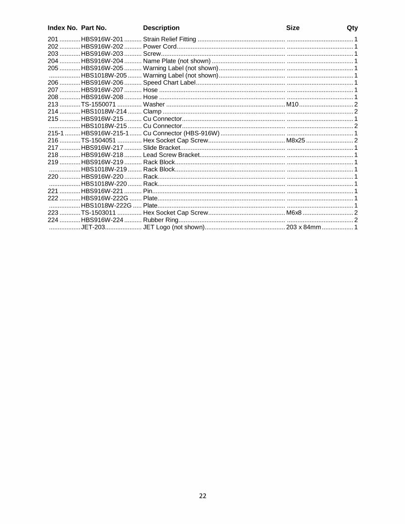
22
Index No. Part No. Description Size Qty 201 ............ HBS916W-201 .......... Strain Relief Fitting .................................................. ...................................... 1 202 ............ HBS916W-202 .......... Power Cord .............................................................. ...................................... 1 203 ............ HBS916W-203 .......... Screw ....................................................................... ...................................... 1 204 ............ HBS916W-204 .......... Name Plate (not shown) .......................................... ...................................... 1 205 ............ HBS916W-205 .......... Warning Label (not shown) ...................................... ...................................... 1 .................. HBS1018W-205 ........ Warning Label (not shown) ...................................... ...................................... 1 206 ............ HBS916W-206 .......... Speed Chart Label ................................................... ...................................... 1 207 ............ HBS916W-207 .......... Hose ........................................................................ ...................................... 1 208 ............ HBS916W-208 .......... Hose ........................................................................ ...................................... 1 213 ............ TS-1550071 .............. Washer .................................................................... M10 ............................... 2 214 ............ HBS1018W-214 ........ Clamp ...................................................................... ...................................... 2 215 ............ HBS916W-215 .......... Cu Connector........................................................... ...................................... 1 .................. HBS1018W-215 ........ Cu Connector........................................................... ...................................... 2 215-1 ......... HBS916W-215-1 ....... Cu Connector (HBS-916W) ..................................... ...................................... 1 216 ............ TS-1504051 .............. Hex Socket Cap Screw ............................................ M8x25 ........................... 2 217 ............ HBS916W-217 .......... Slide Bracket............................................................ ...................................... 1 218 ............ HBS916W-218 .......... Lead Screw Bracket................................................. ...................................... 1 219 ............ HBS916W-219 .......... Rack Block ............................................................... ...................................... 1 .................. HBS1018W-219 ........ Rack Block ............................................................... ...................................... 1 220 ............ HBS916W-220 .......... Rack......................................................................... ...................................... 1 .................. HBS1018W-220 ........ Rack......................................................................... ...................................... 1 221 ............ HBS916W-221 .......... Pin............................................................................ ...................................... 1 222 ............ HBS916W-222G ....... Plate......................................................................... ...................................... 1 .................. HBS1018W-222G ..... Plate......................................................................... ...................................... 1 223 ............ TS-1503011 .............. Hex Socket Cap Screw ............................................ M6x8 ............................. 2 224 ............ HBS916W-224 .......... Rubber Ring............................................................. ...................................... 2 .................. JET-203..................... JET Logo (not shown).............................................. 203 x 84mm .................. 1
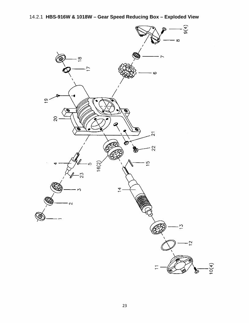
23
14.2.1 HBS-916W & 1018W – Gear Speed Reducing Box – Exploded View

24
14.2.2 HBS-916W & 1018W – Gear Speed Reducing Box – Parts List
Index No. Part No. Description Size Qty 1 ................ HBS916W-94-01 ....... Oil Seal .................................................................... 35x55x8 mm ................. 1 2 ................ HBS916W-94-02 ....... Bearing .................................................................... 30207 ............................ 1 3 ................ HBS916W-94-03 ....... Bearing .................................................................... 6207 .............................. 1 4 ................ HBS916W-94-04 ....... Shaft ........................................................................ ...................................... 1 5 ................ HBS916W-94-05 ....... Key........................................................................... 8x7x30 mm ................... 1 6 ................ HBS916W-94-06 ....... Gear Wheel.............................................................. ...................................... 1 7 ................ HBS916W-94-07 ....... Bearing .................................................................... 6206 .............................. 1 8 ................ HBS916W-94-08 ....... Output Shaft Cover .................................................. ...................................... 1 9 ................ HBS916W-94-09 ....... Output Hex Cap Screw ............................................ M10x20 ......................... 4 10 .............. HBS916W-94-10 ....... Input Hex Cap Screw ............................................... M8x20 ........................... 4 11 .............. HBS916W-94-11 ....... Input Shaft Cover ..................................................... ...................................... 1 12 .............. HBS916W-94-12 ....... Washer .................................................................... ...................................... 1 13 .............. HBS916W-94-13 ....... Bearing .................................................................... 6025 .............................. 1 .................. HBS916W-94-13N .... Bearing .................................................................... 30205 ............................ 1 14 .............. HBS916W-94-14 ....... Input Shaft ............................................................... ...................................... 1 15 .............. HBS916W-94-15 ....... Key........................................................................... 7x7x60 mm ................... 1 16 .............. HBS916W-94-16 ....... Bearing .................................................................... 6205 .............................. 2 17 .............. HBS916W-94-17 ....... C-Ring...................................................................... R52 ............................... 1 18 .............. HBS916W-94-18 ....... Oil Seal .................................................................... 25x52x8 mm ................. 1 19 .............. HBS916W-94-19 ....... Vent Bolt .................................................................. ...................................... 1 20 .............. HBS916W-94-20 ....... Gear Box.................................................................. ...................................... 1 21 .............. HBS916W-94-21 ....... Oil Lens.................................................................... ...................................... 1 22 .............. HBS916W-94-22 ....... Draw Plug ................................................................ ...................................... 1 23 .............. HBS916W-94-23 ....... Key........................................................................... 7x7x45 mm ................... 1
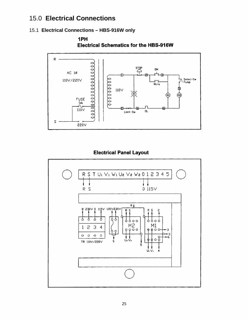
25
15.0 Electrical Connections
15.1 Electrical Connections – HBS-916W only

26
15.2 Electrical Connections – HBS-1018W only

27
This page intentionally left blank.

28
427 New Sanford Road LaVergne, Tennessee 37086
Phone: 800-274-6848 www.jettools.com