operating instructions and parts manual …content.jettools.com/manuals/708599k_man.pdf ·...
TRANSCRIPT

Operating Instructions and Parts Manual Combination Belt/Disc Sander Model JSG-6DC
with optional open stand with optional closed stand
WALTER MEIER (Manufacturing) Inc. 427 New Sanford Road LaVergne, Tennessee 37086 Part No. M-708598 Ph.: 800-274-6848 Revision G 03/2010 www.waltermeier.com Copyright © 2010 Walter Meier (Manufacturing) Inc.

2
Warranty and Service Walter Meier (Manufacturing) Inc., warrants every product it sells. If one of our tools needs service or repair, one of our Authorized Service Centers located throughout the United States can give you quick service. In most cases, any of these Walter Meier Authorized Service Centers can authorize warranty repair, assist you in obtaining parts, or perform routine maintenance and major repair on your JET® tools. For the name of an Authorized Service Center in your area call 1-800-274-6848. MORE INFORMATION Walter Meier is consistently adding new products to the line. For complete, up-to-date product information, check with your local Walter Meier distributor, or visit waltermeier.com. WARRANTY JET products carry a limited warranty which varies in duration based upon the product (MW = Metalworking, WW = Woodworking).
WHAT IS COVERED? This warranty covers any defects in workmanship or materials subject to the exceptions stated below. Cutting tools, abrasives and other consumables are excluded from warranty coverage. WHO IS COVERED? This warranty covers only the initial purchaser of the product. WHAT IS THE PERIOD OF COVERAGE? The general JET warranty lasts for the time period specified in the product literature of each product. WHAT IS NOT COVERED? Five Year Warranties do not cover woodworking (WW) products used for commercial, industrial or educational purposes. Woodworking products with Five Year Warranties that are used for commercial, industrial or education purposes revert to a One Year Warranty. This warranty does not cover defects due directly or indirectly to misuse, abuse, negligence or accidents, normal wear-and-tear, improper repair or alterations, or lack of maintenance. HOW TO GET SERVICE The product or part must be returned for examination, postage prepaid, to a location designated by us. For the name of the location nearest you, please call 1-800-274-6848. You must provide proof of initial purchase date and an explanation of the complaint must accompany the merchandise. If our inspection discloses a defect, we will repair or replace the product, or refund the purchase price, at our option. We will return the repaired product or replacement at our expense unless it is determined by us that there is no defect, or that the defect resulted from causes not within the scope of our warranty in which case we will, at your direction, dispose of or return the product. In the event you choose to have the product returned, you will be responsible for the shipping and handling costs of the return. HOW STATE LAW APPLIES This warranty gives you specific legal rights; you may also have other rights which vary from state to state. LIMITATIONS ON THIS WARRANTY WALTER MEIER (MANUFACTURING) INC., LIMITS ALL IMPLIED WARRANTIES TO THE PERIOD OF THE LIMITED WARRANTY FOR EACH PRODUCT. EXCEPT AS STATED HEREIN, ANY IMPLIED WARRANTIES OR MERCHANTABILITY AND FITNESS ARE EXCLUDED. SOME STATES DO NOT ALLOW LIMITATIONS ON HOW LONG THE IMPLIED WARRANTY LASTS, SO THE ABOVE LIMITATION MAY NOT APPLY TO YOU. WALTER MEIER SHALL IN NO EVENT BE LIABLE FOR DEATH, INJURIES TO PERSONS OR PROPERTY, OR FOR INCIDENTAL, CONTINGENT, SPECIAL, OR CONSEQUENTIAL DAMAGES ARISING FROM THE USE OF OUR PRODUCTS. SOME STATES DO NOT ALLOW THE EXCLUSION OR LIMITATION OF INCIDENTAL OR CONSEQUENTIAL DAMAGES, SO THE ABOVE LIMITATION OR EXCLUSION MAY NOT APPLY TO YOU. Walter Meier sells through distributors only. The specifications in Walter Meier catalogs are given as general information and are not binding. Members of Walter Meier reserve the right to effect at any time, without prior notice, those alterations to parts, fittings, and accessory equipment which they may deem necessary for any reason whatsoever. JET® branded products are not sold in Canada by Walter Meier.

3
Table of Contents Warranty and Service..........................................................................................................................2 Table of Contents ...............................................................................................................................3 Warning .............................................................................................................................................4 Introduction ........................................................................................................................................6 Specifications .....................................................................................................................................6 On/Off Switch Padlock ........................................................................................................................7 Grounding Instructions ........................................................................................................................8
115 Volt Operation ..........................................................................................................................8 230 Volt Operation ..........................................................................................................................8 Extension Cords ..............................................................................................................................9
Unpacking ........................................................................................................................................ 10 Assembly ......................................................................................................................................... 12
Disc Table..................................................................................................................................... 12 Belt Table ..................................................................................................................................... 13 Installing Abrasives........................................................................................................................ 13 Workstop Assembly ....................................................................................................................... 14 Dust Collection .............................................................................................................................. 15
Adjustments ..................................................................................................................................... 15 Belt Table Adjustment.................................................................................................................... 15 Belt Arm Orientation ...................................................................................................................... 16 Limit Screw Adjustment ................................................................................................................. 16 Disc Table Adjustment ................................................................................................................... 16 Miter Gauge .................................................................................................................................. 17 Belt Tracking Adjustment ............................................................................................................... 18 Belt Replacement .......................................................................................................................... 18 Abrasive Disc Replacement ........................................................................................................... 18
Maintenance .................................................................................................................................... 18 Troubleshooting ................................................................................................................................ 19 Optional Accessories ........................................................................................................................ 19 Replacement Parts ........................................................................................................................... 19
JSG-6DC Belt/Disc Sander Assembly ............................................................................................. 20 Parts List for JSG-6DC Belt/Disc Sander Assembly ......................................................................... 21 Closed Stand Assembly (Optional) ................................................................................................. 24 Open Stand Assembly (Optional).................................................................................................... 25 Parts List for Open Stand Assembly (Optional) ................................................................................ 25 Electrical Connections ................................................................................................................... 26

4
Warning
1. Read and understand the entire owner’s manual before attempting assembly or operation.
2. Read and understand the warnings posted on the machine and in this manual. Failure to comply with all of these warnings may cause serious injury.
3. Replace the warning labels if they become obscured or removed.
4. This sander is designed and intended for use by properly trained and experienced personnel only. If you are not familiar with the proper and safe operation of a belt/disc sander, do not use until proper training and knowledge have been obtained.
5. Don’t use power tools in damp or wet locations, or expose them to rain.
6. This sander is intended to be used with wood and wood products only. Use of this sander and a dust collector with metal products is a potential fire hazard. If a dust collector is not used with this machine, remove the dust chutes.
7. Do not use this sander for other than its intended use. If used for other purposes, Walter Meier (Manufacturing), Inc., disclaims any real or implied warranty and holds itself harmless from any injury that may result from that use.
8. Always wear approved safety glasses/face shields while using this sander. (Note: Everyday eyeglasses only have impact resistant lenses; they are not safety glasses.) Also use face or dust masks if the cutting operation is dusty.
9. Before operating this sander, remove tie, rings, watches and other jewelry, and roll sleeves up past the elbows. Remove all loose clothing and confine long hair. Non-slip footwear or anti-skid floor strips are recommended. Do not wear gloves.
10. Some dust created by power sanding, sawing, grinding, drilling and other construction activities contains chemicals known to cause cancer, birth defects or other reproductive harm. Some examples of these chemicals are:
• Lead from lead based paint. • Crystalline silica from bricks, cement and other masonry products. • Arsenic and chromium from chemically treated lumber.
Your risk of exposure varies, depending on how often you do this type of work. To reduce your exposure to these chemicals, work in a well-ventilated area and work with approved safety equipment, such as face or dust masks that are specifically designed to filter out microscopic particles.
11. Do not operate this machine while tired or under the influence of drugs, alcohol or any medication.
12. Make certain the switch is in the OFF position before connecting the machine to the power supply.
13. Make certain the machine is properly grounded.
14. Make all machine adjustments or maintenance with the machine unplugged from the power source.
15. Remove adjusting keys and wrenches. Form a habit of checking to see that keys and adjusting wrenches are removed from the machine before turning it on.
16. Keep safety guards in place at all times when the machine is in use. If removed for maintenance purposes, use extreme caution and replace the guards immediately after maintenance is complete.
17. Make sure the sander is firmly secured to the stand or bench before use.
18. Check damaged parts. Before further use of the machine, a guard or other part that is damaged should be carefully checked to determine that it will operate properly and perform its intended function. Check for alignment of moving parts, binding of moving parts, breakage of parts, mounting and any other conditions that may affect its operation. A guard or other part that is damaged should be properly repaired or replaced.
19. Provide for adequate space surrounding work area and non-glare, overhead lighting.

5
20. Cluttered areas and benches invite accidents. Keep the area around the machine clean and free of
scrap material, oil and grease.
21. Keep visitors a safe distance from the work area. Keep children away.
22. Make your workshop child proof with padlocks, master switches or by removing starter keys.
23. Give your work undivided attention. Looking around, carrying on a conversation and “horse-play” are careless acts that can result in serious injury.
24. Maintain a balanced stance at all times so that you do not fall or lean against the sanding belt/disc or other moving parts. Do not overreach or use excessive force to perform any machine operation.
25. Use the right tool at the correct speed and feed rate. Do not force a tool or attachment to do a job for which it was not designed. The right tool will do the job better and more safely.
26. Use recommended accessories; improper accessories may be hazardous.
27. Maintain tools with care. Keep tools sharp and clean for the best and safest performance. Follow instructions for lubricating the tool and changing accessories.
28. Support the workpiece adequately; maintain control of the work at all times.
29. Avoid kickback by sanding in accordance with directional arrows. When disc sanding, sand on the downward side of the disc; sanding on the upward side can cause the workpiece to fly up causing injury.
30. Sand with the grain of the wood.
31. Do not sand workpieces that are too small to be safely supported.
32. When sanding a large workpiece, use a support table to help stabilize it.
33. Turn off the machine and disconnect from power before cleaning. Use a brush or compressed air to remove chips or debris — do not use your hands.
34. Do not stand on the machine. Serious injury could occur if the machine tips over.
35. Never leave the machine running unattended. Turn the power off and do not leave the machine until it comes to a complete stop.
36. Remove loose items and unnecessary work pieces from the area before starting the machine.
Familiarize yourself with the following safety notices used in this manual:
This means that if precautions are not heeded, it may result in minor injury and/or possible machine damage.
This means that if precautions are not heeded, it may result in serious or even fatal injury.
- - SAVE THESE INSTRUCTIONS - -

6
Introduction This manual is provided by Walter Meier (Manufacturing) Inc., covering the safe operation and maintenance procedures for a JET Model JSG-6DC Belt/Disc Sander. This manual contains instructions on installation, safety precautions, general operating procedures, maintenance instructions and parts breakdown. This machine has been designed and constructed to provide years of trouble free operation if used in accordance with instructions set forth in this manual. If there are any questions or comments, please contact either your local supplier or Walter Meier. Walter Meier can also be reached at our web site: www.waltermeier.com.
Specifications Model Number ....................................................................................................................... JSG-6DC Stock Numbers: Sander only..................................................................................................................... 708599 Sander with optional closed stand .................................................................................. 708598K Sander with optional open stand ..................................................................................... 708599K Belt Section: Sanding Belt (L x W)(in.) ......................................................................................................48 x 6 Belt Table Tilt (deg.) ...................................................................................................... -20 to 45 Belt Table (L x W)(in.) .............................................................................................. 14-3/4 x 7-1/2 Miter Groove (in.) ............................................................................................................ 3/4 x 3/8 Belt Speed (SFPM)............................................................................................................... 2500 Belt Table Positive Stops (deg.)...................................................................................... 45 and 90 Disc Section: Disc Diameter (in.).................................................................................................................... 12 Arbor Size (in.) ........................................................................................................................ 3/4 Disc Table Tilt (deg.) ..................................................................................................... -25 to 45 Disc Table (L x W)(in.) ................................................................................................... 16-1/2 x 9 Miter Groove (in.) ............................................................................................................ 3/4 x 3/8 Disc Speed (RPM)................................................................................................................ 1725 Disc Table Positive Stops (deg.) ..................................................................................... 45 and 90 Dust Port Diameter (in.)....................................................................................................................... 4 Dust Collection Recommended Minimum Capacity (CFM) ................................................................. 450 Motor ........................................................................... TEFC Induction (Capacitor Start), 1-1/2HP, 1PH, 115/230V (pre-wired 115V), 12.8/6.2A, 60Hz Overall Dimensions: with Belt Arm Horizontal (L x W x H/in.) ......................................................................... 35 x 22 x 18 with Belt Arm Vertical (L x W x H/in.) ........................................................................ 35 x 22 x 34-1/2 Footprint (in.) ................................................................................................................. 18-1/2 x 15 Approximate Weight (Net/Shipping)(lbs.) ....................................................................................215/229 Accessory Stands: Approximate Weight of Open Stand (Net/Shipping)(lbs.)................................................................. 25/28 Approximate Weight of Closed Stand (Net/Shipping)(lbs.) .............................................................. 55/61
The above specifications were current at the time this manual was published, but because of our policy of continuous improvement, Walter Meier reserves the right to change specifications at any time and without prior notice, without incurring obligations.

7
On/Off Switch Padlock The Sander is equipped with a push-button switch that will accept a safety padlock (not included). To safeguard your machine from unauthorized operation and accidental starting by young children, the use of a padlock is highly recommended.
A padlock, stock no. 709012-A, is available from your local authorized JET distributor, or by calling Walter Meier (Manufacturing) Inc., at the phone number on the cover of this manual.
To lock out the switch:
1. Open the padlock. See Figure 1.
2. Insert through holes in the start button.
3. Close the padlock.
4. Secure the key in a safe place.
Figure 1

8
Grounding Instructions
Electrical connections must be made by a qualified electrician in compliance with all relevant codes. This machine must be properly grounded to help prevent electrical shock and possible fatal injury.
In the event of a malfunction or breakdown, grounding provides a path of least resistance for electric current to reduce the risk of electric shock. This tool is equipped with an electric cord having an equipment-grounding conductor and a grounding plug. The plug must be plugged into a matching outlet that is properly installed and grounded in accordance with all local codes and ordinances.
Do not modify the plug provided. If it will not fit the outlet, have the proper outlet installed by a qualified electrician.
Improper connection of the equipment-grounding conductor can result in a risk of electric shock. The conductor, with insulation having an outer surface that is green with or without yellow stripes, is the equipment-grounding conductor. If repair or replacement of the electric cord or plug is necessary, do not connect the equipment-grounding conductor to a live terminal.
Check with a qualified electrician or service personnel if the grounding instructions are not completely understood, or if in doubt as to whether the tool is properly grounded. Use only three wire extension cords that have three-prong grounding plugs and three-pole receptacles that accept the tool’s plug.
Repair or replace a damaged or worn cord immediately.
115 Volt Operation As received from the factory, your sander is wired to run at 115 volt operation. This sander when wired for 115 volts, is intended for use on a circuit that has an outlet and a plug that looks the one illustrated in Figure 2. A temporary adapter, which looks like the adapter illustrated in Figure 3, may be used to connect this plug to a two-pole receptacle, as shown in Figure 3 if a properly grounded outlet is not available. The temporary adapter should only be used until a properly grounded outlet can be installed by a qualified electrician. This adapter is not applicable in Canada. The green colored rigid ear, lug, or tab, extending from the adapter, must be connected to a permanent ground such as a properly grounded outlet box, as shown in Figure 3. It is recommended that the JSG-6DC Belt/Disc Sander, when operated at 115 volt, be connected to a grounded and dedicated, minimum 30 amp circuit with a 30 amp circuit breaker or time delay fuse. Local codes take precedence over recommendations.
Figure 2 Figure 3
230 Volt Operation If 230V, single-phase operation is desired, the following instructions must be followed:
1. Disconnect the machine from the power source.
2. This sander is supplied with four motor leads that are connected for 115V operation, as shown in Figure 4. Remove the switch box, and reconnect these four motor leads for 230V operation, as shown in Figure 5. Re-install the switch box.

9
3. The 115V attachment plug (shown in Figure 6) supplied with the sander, must be replaced with a UL/CSA listed plug suitable for 230V operation (shown in Figure 7). Contact your local authorized Walter Meier (Manufacturing) Inc., service center or qualified electrician for proper procedures to install the plug. The sander must comply with all local and national codes after the 230 volt plug is installed.
4. The band saw with a 230 volt plug should only be connected to an outlet having the same configuration (see Figure 7). No adapter is available or should be used with the 230 volt plug.
Important: In all cases (115 or 230 volts), make certain the receptacle in question is properly grounded. If you are not sure, have a registered electrician check the receptacle.
It is recommended that the JSG-6DC Belt/Disc Sander, when operated at 230 volt, be connected to a grounded and dedicated, minimum 15 amp circuit with a 15 amp circuit breaker or time delay fuse. Local codes take precedence over recommendations.
Figure 4 Figure 5
Figure 6
Extension Cords If an extension cord is necessary, make sure the cord rating is suitable for the amperage listed on the machine’s motor plate. An undersize cord will cause a drop in line voltage resulting in loss of power and overheating.
Use the chart in Figure 7 as a general guide in choosing the correct size extension cord for the Bandsaw. If in doubt, use the next heavier gauge. The smaller the gauge number, the heavier the cord.
Recommended Minimum Gauge (AWG) of Extension Cords
Ampere Rating
Volts Total Length of Cord in Feet 115 V 25 ft. 50 ft. 100 ft. 150 ft. 230 V 50 ft. 100 ft. 200 ft. 300 ft.
AWG < 6 18 16 16 14
6 to 10 18 16 14 12 10 to 12 16 16 14 12 12 to 16 14 12 Not recommended Not recommended
Figure 7

10
Unpacking Open shipping carton(s) and check for shipping damage. Report any damage immediately to your distributor and shipping agent. Do not discard any shipping material until the Sander is assembled and running properly.
Compare the contents of your carton(s) with the following parts list to make sure all parts are intact. Missing parts, if any, should be reported to your distributor. Read the instruction manual thoroughly for assembly, maintenance and safety instructions.
Contents of Main Carton
See Figure 8.
1 Belt/Disc Sander (A) 1 Belt Sanding Table (B) 1 Disc Sanding Table (C) 1 Miter Gauge Assembly (D) 1 Workstop Assembly (E) 2 Lock Knobs (F) 1 Belt Tensioning Handle w/ Nut (G) 1 Table Lock Handle (H) 1 12-inch Abrasive Disc (I) 1 6 x 48-inch Abrasive Belt (J) 1 Operator’s Manual (not shown) 1 Warranty Card (not shown) 1 Hardware Bag (K), containing: 1 Hex Key, 6mm 4 Hex Cap Screws, M10 x 80 9 Flat Washers, M10 4 Lock Washers, M10 4 Hex Nuts, M10
Figure 8

11
Contents of Closed Stand Carton:
(Optional Accessory – p/n 708598)
See Figure 9.
1 Stand 1 Owner’s Manual (not shown) 1 Hardware Bag*, containing: 4 Hex Cap Screws, M10 x 80 8 Flat Washers, M10 4 Lock Washers, M10 4 Hex Nuts, M10
(*Note: The closed stand hardware bag contains the same fasteners as the sander hardware bag, and will not be needed if you purchased sander and stand together.)
Contents of Open Stand Carton:
(Optional Accessory – p/n 708566)
See Figure 10.
1 Top 4 Legs 4 Long Cross Braces 4 Short Cross Braces 1 Owner’s Manual (not shown) 1 Hardware Bag, containing: 40 Carriage Bolts, M8x16 40 Lock Washers, M8 40 Flat Washers, M8 40 Hex Nuts, M8
Figure 9
(Optional Accessory)
Figure 10
(Optional Accessory)

12
Assembly Tools required for assembly: 4mm Hex Key 6mm Hex Key (provided) 13mm open-end wrench (2) 11/16” wrenches or sockets
Machine is heavy! Use caution when lifting out of the shipping carton and moving to a final location. Stand or bench must be stable enough to support heavy weight.
1. Use a hoist with straps to remove the Sander from the carton. Prevent straps from contacting any levers or switches while lifting.
2. Carefully position the machine on a workbench or one of the optional JET stands. (Consult the assembly instructions that accompanied the stand.)
3. Bolt the unit firmly to secure it in position. Figure 11 shows it being bolted to the optional closed stand. Use the four M10x80 hex cap screws, with M10 lock washers, flat washers and hex nuts. Tighten hex nut while holding the screw head stationary, using two 11/16” wrenches. Remove lifting straps.
4. Exposed metal surfaces have been factory-coated with a protectant. Remove this using a soft cloth and a solvent or cleaner/ degreaser. (Note: Keep solvents away from painted surfaces and plastic parts, and do not use an abrasive pad, as it may scratch the polished metal surfaces.)
Machine should be dis-connected from power during all assembly procedures.
Disc Table 1. Remove the left and right trunnion brackets
(A, Figure12) from the trunnion holder (B).
2. Make sure the stop block (shown in Figure 23) is flipped out of the way.
3. Place the disc table on top of the trunnion assemblies and position each trunnion bracket (A) so that it slips onto the threaded stud and two pins of the trunnion holder (B), while engaging the lip of the table trunnion (C).
Figure 11
(closed stand optional)
Figure 12
Figure 13

13
Note: The trunnion brackets are not identical; make sure the bracket with the raised indicator line is installed on the left side of the table.
4. Install a lock knob (D) on each threaded stud and tighten to hold the table in position.
5. See “Adjustments” section for further instruction on adjusting the disc table.
Belt Table 1. Loosen the sanding platen lock screw (E,
Figure 13) with a 6mm hex wrench, and tilt the belt arm to a vertical position. Re-tighten the lock screw.
2. Guide the belt table trunnion onto the stud, as shown in Figure 14. The raised track on the trunnion must fit into the groove on the belt arm.
3. Place the remaining M10 flat washer onto the stud (Figure 15).
4. Thread the nut of the table lock handle (Figure 15) onto the stud. To do this quickly, pull out on the handle, while tightening the nut with a 4mm hex wrench. When the nut is fully tightened onto the stud, release the handle, making sure it seats itself back onto the nut.
Note: The table lock handle can be repositioned at any time for convenience by pulling out on the handle, rotating it to new position, then releasing it. Make sure it re-seats itself on the nut.
5. Screw the belt tensioning handle (Figure 16) into the threaded hole in the belt tracking assembly, and tighten the hex nut against the shaft with a 13mm wrench.
6. See “Adjustments” section for further instruction on adjusting the belt table.
Installing Abrasives Abrasive Disc
Note: You may wish to check the angle setting of the table before installing the abrasive disc. See “Disc Table Adjustment”.
To install the abrasive disc:
1. Disconnect machine from power source.
2. Make sure the aluminum disc is clean and dry.
3. Peel the backing from the abrasive and carefully insert it between disc and table; align and press into place.
Figure 14
Figure 15
Figure 16

14
4. Rotate disc a half turn and press other half of abrasive into place. Make sure to remove any entrapped air by pressing all parts of the abrasive against the disc.
Abrasive Belt
1. Disconnect machine from power source.
2. Raise the belt arm to vertical position.
3. Loosen lock screw and open left side panel.
4. Most brands of replacement abrasives are directional, and must be installed in the proper direction. Directional belts are so indicated on the backing material by arrows. The direction of the abrasive should match that of the arrow on the platen assembly (Figure 17).
NOTE: Failure to comply with abrasive belt directional instructions may result in premature belt breakage.
5. Once the belt direction has been determined, pull the belt tensioning handle toward you with one hand, while using the other hand to slide the belt onto both drums and over the platen pad. See Figure 17.
6. Center the belt on the platen and release the belt tensioning handle.
7. Before operating, the belt should be tracked. See “Belt Tracking Adjustment.”
Workstop Assembly When the sanding belt is to be used in the horizontal position, the table may be used as a fence; or the table may be removed and the workstop assembly installed.
Refer to Figure 18.
1. Remove table and trunnion assembly by removing the table lock handle and washer.
2. Slide workstop bracket onto stud and fasten with the washer and lock handle.
3. Adjust workstop to clear belt before starting machine.
Figure 17
Figure 18

15
Dust Collection It is strongly recommended that a dust collection system (not included) be connected to the sander. Mount a 4-inch hose to the sander’s dust port and secure with a hose clamp. (Note: Dryer vent hose is not suitable for such use).
The dust collector should have sufficient capacity for this size machine; a minimum rating of 450 CFM (cubic feet per minute) is recommended.
A variety of JET dust collectors is available; see our website at www.waltermeier.com.
Adjustments Tools required for adjustments:
3mm hex key 6mm hex key (provided) 10mm wrench 13mm wrench Combination and/or machinist’s square Cross-point Screwdriver
Belt Table Adjustment 1. Disconnect machine from the power source.
2. Place a square on the table and up against the platen or abrasive belt, as shown in Figure 19.
3. Loosen the table lock handle and move the table until the square sits flush to both surfaces at 90°. Tighten the lock handle.
4. Place a combination square in the miter gauge slot and check the distance from the slot to the face of the platen. See Figure 20. Slide the square along the slot to the other side of the platen and check the distance. The distances should be equal to ensure that the miter gauge travels parallel to the belt.
5. If the table is not parallel, loosen the screws below the table (A, Figure 21) with a 13mm wrench, and nudge the table until parallel. Re-tighten screws.
Note: Always maintain a gap of approximately 1/16” between the table edge and the abrasive belt.
Once the table is square and parallel to the belt, verify the stops, as follows:
Figure 19
Figure 20
Figure 21

16
Adjust 90° Stop
6. With the table locked at 90°, loosen the hex nut on the 90° stop, and adjust the set screw to seat against the stop block. See Figure 19. Re-tighten hex nut to secure the setting.
7. If angle indicator adjustment is necessary, loosen the screw and shift the pointer to zero, and re-tighten the screw.
Adjust 45° Stop
8. Flip the stop block out of the way, and tilt the table down to 45°. Verify the setting of the 45° angle stop (Figure 19). Use the same procedure as above but with a 45° measuring device on the table. Correct the stop as needed.
Belt Arm Orientation Loosen the belt arm lock screw (see Figure 13) to tilt the belt arm to vertical or horizontal position. The belt arm can also be secured at any angle between. Always tighten the screw before operating.
Note: Belt tracking may require re-adjustment if the belt assembly is moved from vertical to horizontal or back again.
Limit Screw Adjustment This set screw (Figure 22) limits the rotation of the belt arm to vertical and horizontal positions, and has been pre-set. If it should ever need re-adjustment:
1. Loosen lock nut on the set screw with a 10mm wrench.
2. With a 3mm hex key, turn set screw all the way in until it bottoms out. Back screw out three turns and re-tighten lock nut, while holding screw in place.
Disc Table Adjustment 1. Disconnect machine from power source.
2. Place a square on the table and against the disc. See Figure 23. Loosen both lock knobs, move the table until the square sits flush to both surfaces at 90°, and re-tighten both knobs. Note: You may need to pivot the stop block out of the way.
3. Place a combination square in the miter gauge slot and check the distance from the slot to face of the disc. See Figure 24. Slide the square along the slot to the other side of the disc and check the distance. The distances should be equal to ensure that the miter gauge travels parallel to the disc.
Figure 22
Figure 23
Figure 24

17
4. If table is not parallel, loosen the four screws holding the table to the trunnions (B, Figure 25) with a 12mm wrench, and nudge the table until parallel. Re-tighten screws.
Note: Always maintain a gap of approximately 1/16” between the table edge and the abrasive disc.
Once the table is square and parallel to the disc, verify the stops, as follows:
Adjust 90° Stop
5. Loosen lock nut on the 90° stop (Figure 23) with a 10mm wrench. Turn the set screw down (3mm hex key) to contact the table. Re-tighten lock nut.
Adjust 45° Stop
6. To adjust the 45° stop, pivot the 90° stop block out of the way, and tilt the table down against the 45° stop screw (Figure 25). Check the angle with a 45° measuring device on the table and against the disc.
7. If adjustment is necessary, loosen the hex nut, turn the stop screw as needed, and re-tighten the hex nut to secure the setting.
Adjust Rear Stop
The rear stop (Figure 26) is used when tilting the disc table upward. It can be set to limit the table tilt to about minus 15°. To tilt the table to the full minus 25°, remove the rear stop screw and nut.
Miter Gauge Refer to Figure 27.
Check the zero setting of the miter gauge. (Note: Make sure the miter slot is parallel to the disc surface.)
1. Place the miter gauge into the disc table slot and loosen the miter gauge knob.
2. Place a square against miter gauge and disc so that it sits flush against both surfaces.
3. Tighten the knob, and check the zero setting. If necessary, adjust the pointer to the zero mark.
Figure 25
Figure 26
Figure 27

18
Belt Tracking Adjustment The belt should run at the center of the belt arm without veering to the left or right. Check this as follows:
1. Disconnect machine from the power source.
2. Rotate the belt by hand and observe how it tracks. The belt should run centered on the belt wheels.
3. If the belt has a tendency to track left or right of center, loosen locking nuts (A, Figure 28).
4. Turn the front screw (B, Figure 28) while turning the belt by hand and observe belt tracking. Once the belt starts to move in the desired direction, stop and turn the rear screw (C) in the same manner. NOTE: These adjustments are sensitive and should be done in small increments.
5. Grasp the tensioning adjustment handle (D) and start the machine. Be ready to pull down on the tension adjustment handle should the belt want to run off the belt wheel.
6. Fine adjustment of the tracking may be necessary. When the tracking has stabilized, slowly release the belt tensioning arm and let the machine run for two minutes.
7. Tighten lock nuts (A) when tracking adjustments are satisfactory.
Belt Replacement 1. Disconnect machine from the power source.
2. Remove the lock knob and open the left side panel.
3. Release belt tension using the handle (D, Figure 28), and slide belt off the wheels.
4. Refer to “Installing Abrasives” section for instructions on installing the new belt.
Abrasive Disc Replacement 1. Disconnect machine from the power source.
2. Slowly work the tip of a knife under the abrasive disc, and work it around the circumference of the disc until abrasive can be removed by hand.
3. Clean the aluminum disc of any residual adhesive, using mineral spirits or similar solvent. Allow to dry.
4. See “Installing Abrasives” for instructions on installing the new abrasive disc.
Figure 28
Maintenance
Before doing maintenance on the machine, disconnect it from the electrical supply by pulling out the plug or switching off the main switch! Failure to comply may cause serious injury.
Wipe the machine down after each use.
Keep exposed metal surfaces clean and rust-free. A light coat of paste wax applied to the tables will help protect the surfaces.
Make periodic inspections of the sander, checking fastener tightness, abrasive wear, tracking accuracy, etc. Listen for any unusual motor noises or vibrations that might indicate bearing fatigue.
(Note: All rotating parts run on sealed ball bearings and do not require lubrication.)
If you will not be using the machine for an extended period, remove the abrasive belt; this will prevent it from stretching and will prolong its life.
If the power cord is worn, cut, or damaged in any way, have it replaced immediately.
19
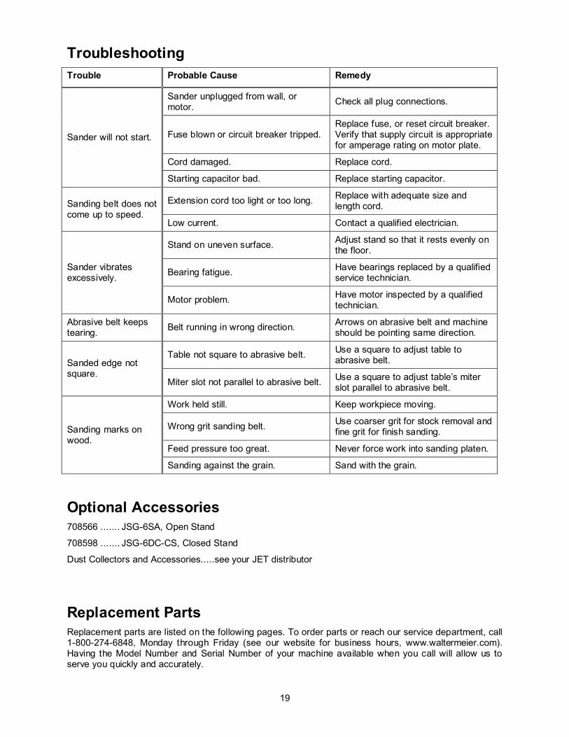
Troubleshooting Trouble Probable Cause Remedy
Sander will not start.
Sander unplugged from wall, or motor. Check all plug connections.
Fuse blown or circuit breaker tripped. Replace fuse, or reset circuit breaker. Verify that supply circuit is appropriate for amperage rating on motor plate.
Cord damaged. Replace cord.
Starting capacitor bad. Replace starting capacitor.
Sanding belt does not come up to speed.
Extension cord too light or too long. Replace with adequate size and length cord.
Low current. Contact a qualified electrician.
Sander vibrates excessively.
Stand on uneven surface. Adjust stand so that it rests evenly on the floor.
Bearing fatigue. Have bearings replaced by a qualified service technician.
Motor problem. Have motor inspected by a qualified technician.
Abrasive belt keeps tearing. Belt running in wrong direction. Arrows on abrasive belt and machine
should be pointing same direction.
Sanded edge not square.
Table not square to abrasive belt. Use a square to adjust table to abrasive belt.
Miter slot not parallel to abrasive belt. Use a square to adjust table’s miter slot parallel to abrasive belt.
Sanding marks on wood.
Work held still. Keep workpiece moving.
Wrong grit sanding belt. Use coarser grit for stock removal and fine grit for finish sanding.
Feed pressure too great. Never force work into sanding platen.
Sanding against the grain. Sand with the grain.
Optional Accessories 708566 ....... JSG-6SA, Open Stand
708598 ....... JSG-6DC-CS, Closed Stand
Dust Collectors and Accessories.....see your JET distributor
Replacement Parts Replacement parts are listed on the following pages. To order parts or reach our service department, call 1-800-274-6848, Monday through Friday (see our website for business hours, www.waltermeier.com). Having the Model Number and Serial Number of your machine available when you call will allow us to serve you quickly and accurately.

20
JSG-6DC Belt/Disc Sander Assembly

21
Parts List for JSG-6DC Belt/Disc Sander Assembly
Index No. Part No. Description Size Qty 1 .............. 612001W ................Base .................................................................................................. 1 2 .............. 612002W ................Base Plate ......................................................................................... 1 3 .............. SF069300 ...............Pan Head Screw (w/flange) .........................M6x12.............................. 6 4 .............. 612003W ................Front Plate ......................................................................................... 1 5 .............. SF069300 ...............Pan Head Screw (w/flange) .........................M6x12.............................. 4 6 .............. 612004W ................Dust Tube .......................................................................................... 2 7 .............. 612005....................Gasket ............................................................................................... 2 8 .............. SF069300 ...............Pan Head Screw (w/flange) .........................M6x12.............................. 8 9 .............. 612006W ................Dust Hood .......................................................................................... 1 10 ............ MA150001W ...........Motor ................................................................................................. 1 ................ 990019....................Centrifugal Switch ............................................................................... 1 ................ 991500....................Start Capacitor ...........................................500MFD, 125VAC............. 1 ................ 991050....................Run Capacitor ............................................50MFD, 250VAC .............. 1 11 ............ CC324101 ...............Power Cord ........................................................................................ 1 12 ............ 150508....................Strain Relief Plate ............................................................................... 1 13 ............ 998623....................Strain Relief ....................................................................................... 1 14 ............ SF059100 ...............Pan Head Screw (w/flange) .........................M5x6 ............................... 2 15 ............ 612007....................Switch Box ......................................................................................... 1 16 ............ 994503....................Switch ................................................................................................ 1 17 ............ ST040400 ...............Tapping Screw ...........................................M4x20.............................. 2 18 ............ 612008....................Pad.................................................................................................... 1 19 ............ SF059100 ...............Pan Head Screw (w/flange) .........................M5x12.............................. 2 20 ............ SR080700 ...............Hex Socket Cap Screw ...............................M8x35.............................. 4 21 ............ 612009W ................Bracket .............................................................................................. 1 22 ............ SR080700 ...............Hex Socket Cap Screw ...............................M8x35.............................. 1 23 ............ NH061000 ...............Nut ............................................................M6 ................................... 1 24 ............ SS060600 ...............Set Screw ..................................................M6x30.............................. 1 25 ............ 610010....................Stop Block.......................................................................................... 1 26 ............ PS054500 ...............Spring Pin ..................................................5x45 mm .......................... 1 27 ............ 612011....................Scale ................................................................................................. 1 28 ............ VS020500 ...............Rivet ..........................................................M2x5 ............................... 3 29 ............ KD050560 ...............Key ............................................................5x5x60 mm ...................... 1 30 ............ 612012....................Drive Roller ........................................................................................ 1 31 ............ 612013....................Flange ............................................................................................... 1 32 ............ NH243600 ...............Nut ............................................................M24 ................................. 1 33 ............ 612014....................Eccentric Shaft Bracket ....................................................................... 1 34 ............ 612015....................Spring Plate ....................................................................................... 3 35 ............ SR109400 ...............Hex Socket Cap Screw ...............................M10x16 ............................ 6 36 ............ 612016....................Nut .................................................................................................... 2 37 ............ 612017....................Adjusting Screw .................................................................................. 2 38 ............ SR069200 ...............Hex Socket Cap Screw ...............................M6x8 ............................... 1 39 ............ 612018....................Eccentric Shaft ................................................................................... 1 40 ............ RS200000 ...............Retaining Ring ............................................S20.................................. 1 41 ............ 612019....................Spring ................................................................................................ 1 42 ............ 612020....................Eccentric Shaft Bushing ...................................................................... 1 43 ............ 612021....................Locating Block .................................................................................... 1 44 ............ SM0606400 .............Countersunk Head Bolt ...............................M6x20.............................. 1 45 ............ 612022....................Follow Roller ...................................................................................... 1 46 ............ BB-6202LLU............Ball Bearing................................................6202LLU .......................... 2 47 ............ RS150000 ...............Retaining Ring .................................................................................... 1 48 ............ 612023W ................Sanding Platen ................................................................................... 1 49 ............ 612024....................Sanding Belt Pad ................................................................................ 1 50 ............ ...............................Sanding Belt (local purchase) .............................................................. 1 51 ............ SR100700 ...............Hex Socket Cap Screw ...............................M10x35 ............................ 2 52 ............ WF102830 ..............Flat Washer................................................M10 ................................. 1 53 ............ 612026W ................Sanding Belt Guard ............................................................................ 1 54 ............ 612027W ................Outlet Guard ...................................................................................... 1

22
55 ............ 612028....................Hinge ................................................................................................. 1 56 ............ TS049200 ...............Tapping Screw ...........................................M4x8 ............................... 8 57 ............ 612029W ................Access Door ....................................................................................... 1 58 ............ 612030....................Hinge ................................................................................................. 2 59 ............ ST049200 ...............Tapping Screw ...........................................M4x8 ............................... 8 60 ............ 612031....................Lock Knob .......................................................................................... 1 61 ............ SF069300 ...............Pan Head Screw (w/flange) .........................M6x12.............................. 6 62 ............ KD050525 ...............Key ............................................................5x5x25 mm ...................... 1 63 ............ 612032W ................Disc Guard ......................................................................................... 1 65 ............ SP080400 ...............Pan Head Screw.........................................M8x20.............................. 4 66 ............ 612033....................Sanding Disc ...................................................................................... 1 67 ............ ...............................Disc Abrasive (local purchase)............................................................. 1 68 ............ SS060200 ...............Set Screw ..................................................M6x10.............................. 2 69 ............ 612035....................Table Bracket ..................................................................................... 1 70 ............ 612010....................Stop Block.......................................................................................... 1 71 ............ NH061000 ...............Nut ............................................................M6 ................................... 1 72 ............ SS060500 ...............Set Screw ..................................................M6x25.............................. 1 73 ............ PS052500 ...............Spring Pin ..................................................5x25 mm .......................... 1 74 ............ 150031....................Pin ..................................................................................................... 1 75 ............ SH080500 ...............Hex Cap Bolt ..............................................M8x25.............................. 1 76 ............ WF081818 ..............Flat Washer................................................M8 ................................... 1 77 ............ WS080000 ..............Lock Washer ..............................................M8 ................................... 1 78 ............ 612037....................Table Bracket ..................................................................................... 1 79 ............ SH080800 ...............Hex Cap Bolt ..............................................M8x40.............................. 2 80 ............ PS063000 ...............Spring Pin ..................................................6x30 mm .......................... 4 81 ............ 150031....................Pin ..................................................................................................... 2 82 ............ SH089400 ...............Hex Cap Bolt ..............................................M8x16.............................. 4 83 ............ WF081818 ..............Flat Washer................................................M8 ................................... 4 84 ............ WS080000 ..............Lock Washer ..............................................M8x ................................. 4 85 ............ 612038....................Trunnion Bracket ................................................................................ 1 86 ............ 990551....................Knob .................................................................................................. 2 87 ............ 612039W ................Sanding Table .................................................................................... 1 88 ............ 612040W ................Trunnion ............................................................................................ 1 89 ............ 612041....................Sliding Plate ....................................................................................... 1 90 ............ PS041200 ...............Spring Pin ..................................................4x12 mm .......................... 2 91 ............ 612056....................Pointer ............................................................................................... 1 92 ............ SF059100 ...............Pan Head Screw (w/flange) .........................M5x6 ............................... 1 93 ............ SH080400 ...............Hex Cap Bolt ..............................................M8x20.............................. 3 94 ............ WF081818 ..............Flat Washer................................................M8 ................................... 3 95 ............ WS080000 ..............Lock Washer ..............................................M8 ................................... 3 ................ AA612042 ...............Workstop Assembly CP....................................................................... 1 96 ............ 612042W ................Fence ................................................................................................ 1 97 ............ 612043W ................Support Arm ....................................................................................... 1 98 ............ 612044....................Stud ................................................................................................... 1 99 ............ WF102825 ..............Flat Washer................................................M10 ................................. 1 100 .......... 612045W ................Table ................................................................................................. 1 101 .......... 612046....................Trunnion ............................................................................................ 2 102 .......... SH089400 ...............Hex Cap Bolt ..............................................M8x16.............................. 4 103 .......... WS080000 ..............Lock Washer ..............................................M8 ................................... 4 ................ AA150401 ...............Miter Gauger Assembly CP ................................................................. 1 104 .......... 150401....................Guide Bar........................................................................................... 1 105 .......... 199083....................Gauge Body ....................................................................................... 1 106 .......... PS051200 ...............Spring Pin ..................................................5x12 mm .......................... 1 107 .......... 612036....................Knob .................................................................................................. 1 108 .......... 150406....................Gasket ............................................................................................... 1 109 .......... 150402....................Pointer ............................................................................................... 1 110 .......... SP550200 ...............Pan Head Screw.........................................3/16” x 1/4"....................... 1 111 .......... 612047....................Lock Knob Assembly .......................................................................... 1 112 .......... 612048....................Handle ............................................................................................... 1 113 .......... NH081300 ...............Nut ............................................................M8 ................................... 1 114 .......... TS-1527071 ............Hex Wrench ...............................................6mm ................................ 1

23
115 .......... NH101700 ...............Nut * ..........................................................M10 ................................. 4 116 .......... SH101600 ...............Hex Cap Bolt * ............................................M10x80 ............................ 4 117 .......... WF102825 ..............Flat Washer................................................M10 ................................. 9 118 .......... WS100000 ..............Lock Washer * ............................................M10 ................................. 4 119 .......... 612052....................Trunnion Holder .................................................................................. 1 120 .......... 612053....................Stud ................................................................................................... 1 121 .......... 612054....................Table Bracket ..................................................................................... 1 122 .......... NH081300 ...............Nut ............................................................M8 ................................... 1 123 .......... SR080500 ...............Hex Socket Cap Screw ...............................M8x25.............................. 1 124 .......... WS060000 ..............Lock Washer ..............................................M6 ................................... 1 125 .......... WS080000 ..............Lock Washer ..............................................M8 ................................... 4 126 .......... NH061000 ...............Nut ............................................................M6 ................................... 2 127 .......... SS060600 ...............Set Screw ..................................................M6x30.............................. 2 * Items included in AH612J1 Hardware Kit

24
Closed Stand Assembly (Optional)
Index No. Part No. Description Size Qty ................ 708598....................Closed Stand Assembly Complete ....................................................... 1 1 .............. AB612062 ...............Closed Stand...................................................................................... 1 2 .............. TS-0060111 ............Hex Cap Screw ..........................................3/8” x 2-1/2”...................... 4 3 .............. TS-1550071 ............Flat Washer................................................M10 x 20 .......................... 9 4 .............. 150105....................Wheel ................................................................................................ 4 5 .............. TS-0640091 ............Nyloc Lock Nut ...........................................3/8” .................................. 5 6 .............. 150103....................Stop ................................................................................................... 2 7 .............. TS-1523031 ............Set Screw ..................................................M6 x 10 ............................ 2 8 .............. 612063....................Stop Shaft .......................................................................................... 1 9 .............. PS042400 ...............Spring Pin ..................................................4 x 24 mm ........................ 1 10 ............ 150106....................Spring ................................................................................................ 1 11 ............ 150104....................Step Plate .......................................................................................... 1 12 ............ 145002....................Door .................................................................................................. 1 13 ............ 150503....................Lock................................................................................................... 1 14 ............ 150527....................Pad.................................................................................................... 2
Hardware used to attach the Sander to the Closed Stand ................ AH612J1 .................Hardware Bag (contains the items below)............................................. 1 ................ TS-229801 ..............Hex Cap Screw (not shown) ........................M10 x 1.5 x 80 .................. 4 ................ TS-1550071 ............Flat Washer (not shown) .............................M10 ................................. 8 ................ TS-1551071 ............Lock Washer (not shown) ............................M10 ................................. 4 ................ TS-1540077 ............Hex Nut (not shown) ...................................M10 x 1.5 ......................... 4

25
Open Stand Assembly (Optional)
Parts List for Open Stand Assembly (Optional)
Index No. Part No. Description Size Qty ................ 708566....................Open Stand Assembly Complete ......................................................... 1 A ............. 612049....................Stand Top (blue) ................................................................................. 1 ................ 612049W ................Stand Top (white) ............................................................................... 1 B ............. 150603....................Stand Leg (blue) ................................................................................. 4 ................ 150603W ................Stand Leg (white) ............................................................................... 4 C ............. SC089400 ...............Carriage Bolt * ............................................M8 x 16 .......................... 40 D ............. WF081818 ..............Flat Washer * .............................................M8 ................................. 40 E ............. WS080000 ..............Lock Washer * ............................................M8 ................................. 40 F.............. NH081300 ...............Hex Nut * ...................................................M8 ................................. 40 G ............. 612051....................Cross Brace – short (blue) ................................................................... 2 ................ 612501W ................Cross Brace – short (white) ................................................................. 2 H ............. 612050....................Cross Brace – long (blue) .................................................................... 2 ................ 612050W ................Cross Brace – long (white) .................................................................. 2 ................ AB612101 ...............Hardware Bag (includes items marked with *) ....................................... 1

26
Electrical Connections

27

28
WALTER MEIER (Manufacturing) Inc. 427 New Sanford Road
LaVergne, Tennessee 37086 Phone: 800-274-6848
www.waltermeier.com