operating instructions circular chart recorders - abb ltd · circular chart recorders 1492 series...
TRANSCRIPT

Circular Chart Recorders
1492 Series
Operating InstructionsIM/1492_15

ABB
The Company
We are an established world force in the design and manufacture of instrumentation for industrialprocess control, flow measurement, gas and liquid analysis and environmental applications.
As a part of ABB, a world leader in process automation technology, we offer customersapplication expertise, service and support worldwide.
We are committed to teamwork, high quality manufacturing, advanced technology and unrivalledservice and support.
The quality, accuracy and performance of the Company’s products result from over 100 yearsexperience, combined with a continuous program of innovative design and development toincorporate the latest technology.
The NAMAS Calibration Laboratory No. 0255 is just one of the ten flow calibration plantsoperated by the Company, and is indicative of our dedication to qualityand accuracy.
Health and SafetyTo ensure that our products are safe and without risk to health, the following points must be noted:
1. The relevant sections of these instructions must be read carefully before proceeding.
2. Warning labels on containers and packages must be observed.
3. Installation, operation, maintenance and servicing must only be carried out by suitably trained personnel and in accordance with theinformation given.
4. Normal safety precautions must be taken to avoid the possibility of an accident occurring when operating in conditions of high pressure and/or temperature.
5. Chemicals must be stored away from heat, protected from temperature extremes and powders kept dry. Normal safe handling proceduresmust be used.
6. When disposing of chemicals ensure that no two chemicals are mixed.
Safety advice concerning the use of the equipment described in this manual or any relevant hazard data sheets (where applicable) may beobtained from the Company address on the back cover, together with servicing and spares information.
Warning – Refer to the manual for instructions
Caution – Risk of electric shock
Protective earth (ground) terminal
Earth (ground) terminal
Direct current supply only
Alternating current supply only
Both direct and alternating current supply
The equipment is protectedthrough double insulation
Electrical Safety
This instrument complies with the requirements of CEI/IEC 61010-1:2001-2 'Safety Requirements for Electrical Equipment forMeasurement, Control and Laboratory Use'. If the instrument is used in a manner NOT specified by the Company, the protectionprovided by the instrument may be impaired.
Symbols
One or more of the following symbols may appear on the instrument labelling:
Information in this manual is intended only to assist our customers in the efficient operation of our equipment. Use of this manual forany other purpose is specifically prohibited and its contents are not to be reproduced in full or part without prior approval of theTechnical Publications Department.
EN ISO 9001:1994
Cert. No. Q05907
EN 29001 (ISO 9001)
Lenno, Italy – Cert. No. 9/90A
0255
Stonehouse, U.K.

1
Section Page
1 INTRODUCTION .......................................................... 2
2 PREPARATION ............................................................ 22.1 Accessories ....................................................... 22.2 Checking the Instrument Code Number ........... 3
3 INSTALLATION ............................................................ 43.1 Siting .................................................................. 43.2 Mounting ............................................................ 4
3.2.1 Wall Mounting ...................................... 43.2.2 Panel Mounting .................................... 53.2.3 Fitting a Carrying Stand ....................... 53.2.4 Post Mounting ...................................... 5
4 ELECTRICAL CONNECTIONS ................................... 64.1 Access to Terminals .......................................... 64.2 Connections, General ....................................... 64.3 Signal Connections ........................................... 7
4.3.1 Selecting the Signal Input Type ........... 74.3.2 Voltage and Current Inputs .................. 84.3.3 Thermocouple (THC) Inputs ................ 84.3.4 3-Lead Resistance Thermometer
(RTD) Inputs ........................................ 84.3.5 2-Lead Resistance Thermometer
(RTD) Inputs ........................................ 84.3.6 Transmitter Power Supply ................... 9
4.4 Isolated Signal Connections ........................... 104.4.1 Selecting the Isolated
Signal Input Type ............................... 104.4.2 Voltage and Current Inputs ................ 114.4.3 Thermocouple (THC) Inputs .............. 114.4.4 3-Lead Resistance Thermometer
(RTD) Inputs ...................................... 124.4.5 2-Lead Resistance Thermometer
(RTD) Inputs ...................................... 124.5 Output Connections ........................................ 13
4.5.1 Relay Connections ............................ 134.5.2 Retransmission Connections ............. 134.5.3 Solid State Relay Drive ..................... 144.5.4 Event Pen (PX105/14 or /15 only) ..... 14
4.6 Power Supply .................................................. 154.6.1 Mains Input Voltage Connections ...... 154.6.2 Selecting the Mains Input Voltage ..... 154.6.3 D.C. Supply ........................................ 15
5 FAMILIARISATION WITH CONTROLS,DISPLAY AND L.E.D. INDICATION .......................... 165.1 Controls ................................................................ 165.2 Display .................................................................. 165.3 Alarm L.E.D. Indication ......................................... 16
6 SETTING UP .............................................................. 176.1 Recorder Start-up ............................................ 176.2 Fitting the Chart ............................................... 176.3 Fitting the Pen Capsule(s) .............................. 18
Section Page
7 OPERATION ............................................................... 197.1 Operating Page 1 ............................................ 207.2 Operating Page 2 ............................................ 20
7.2.1 Programmable Options ...................... 207.2.2 Standard Options ............................... 21
8 PROGRAMMING........................................................ 228.1 Programming, General .................................... 228.2 Program Security Link ..................................... 228.3 To Change the Program, Preparation ............. 228.4 Access to Programming Pages ....................... 248.5 Set Up Input Page ........................................... 248.6 Set Up Display Page ....................................... 278.7 Alarm Indication Page ..................................... 308.8 Calibration Page .............................................. 318.9 Input and Recording Conditions Page ............ 318.10 Alarm Set Up Page ......................................... 318.11 Set Up Module Page ....................................... 33
8.11.1 Module Positions 1,2 and 3 ............... 338.11.2 Module Positions 4, 5 and 6 .............. 348.11.3 Module Position 2 or 3
(Event Pen Module) ........................... 378.11.4 Event Pen Ranges ............................. 37
9 SIMPLE FAULT FINDING .......................................... 389.1 Arc Suppression Capacitors ........................... 38
10 CALIBRATION ........................................................... 3810.1 Calibration, General ........................................ 3810.2 Pen Arm Length Adjustment ........................... 3810.3 Calibration Page
(Automatic Procedure) .................................... 3910.4 Calibration Page
(Manual Procedure) ........................................ 42
11 APPENDICES ............................................................ 4411.1 Alarm Actions .................................................. 44
CONTENTS

2
1 INTRODUCTION
The 1492 programmable circular chart recorder measures,displays and records signals from any of the following inputtypes:
Thermocouple (THC)Resistance thermometer (RTD)Linear current or voltageNon-linear current or voltage from temperature transmittersSquare law and power root, current and voltageOther variables transduced to an acceptable current, voltage
or resistance level
The 1492 recorder is available in one-, two-, and three-channelversions with up to 6 output relays allocated to six set pointswhich in turn may be allocated to any channel or channels.
The recorder is microprocessor-based and requires no rangingcomponents. The input mode may be changed by repositioninga link on the printed circuit board and all other changes toinstrument operation are effected by a simple programmingsequence. Chart revolution time may be programmed in steps ofone hour, from a minimum of 1hr/revolution up to 168hr/revolution.
The recorder may be wall- or panel-mounted or fitted into acarrying stand. A post mounting kit is also available.
2 PREPARATION
2.1 AccessoriesThe following items are packed with the instrument:
Door keysPack of charts (10)Function labelProgram card
Mounting brackets are supplied ready-fitted to the case.

3
1
3
25
4
1
2.2 Checking the Instrument Code Number – Fig. 2.1Unlock the door.
1 Pull the door catch forward and down to open the door,hinged at the left hand edge.
2 Loosen the captive crosshead screw.
3 Swing the chassis forward (hinged at the left hand side).
4 Check the type number on the serial number label againstthe Specification Sheet, reference SS/1492.
Note. Unless the user has requested a particular program therecorder is despatched with a Company Standard Test Programwhich is defined on the program card. If this is not suitable for theuser's requirements the instrument may be re-programmed.See PROGRAMMING on page 22.
5 Write the function of each channel beneath the appropriatecolour on the function label and stick it on the inside edge ofthe door.
Swing the chassis back into position and tighten the captivescrew. Close the door.
Fig. 2.1 Checking the Instrument Code Number

4
370
340
170
360
150
375
20
Dimensions in mm
344
1
3
2
5
64
6
Fig. 3.1 Overall Dimensions Fig. 3.2 Wall Mounting
3 INSTALLATION
EC Directive 89/336/EEC
In order to meet the requirements of the EC Directive 89/336/EEC for EMC regulations, this product must not beused in a non-industrial environment.
3.1 SitingSelect a location:
a) As close as possible to the primary sensing device(s).
b) Free from excessive vibration.
c) Within the temperature limits of 0 to 55°C and humidity limitsof 0 to 80% RH.
d) Where the instrument's protection rating, IP54, is sufficient.
e) Away from strong electrical and magnetic fields. If thesecannot be avoided, particularly in those applications where'walkie-talkies' are expected to be used, screened cableswithin earthed metal conduit must be used.
3.2 Mounting – Fig. 3.1Overall dimensions are shown in Fig. 3.1. The instrumentweighs approximately 10.5kg.
3.2.1 Wall Mounting – Fig. 3.21 Remove the three fixing brackets from the top and sides of
the case.
2 Reverse the brackets and refit to the case with the fixingscrews located in the holes in the brackets (not the slots).Tighten the screws firmly.
3 Mark and drill a mounting hole in the position for the topmounting bracket – the bracket fixing hole is 8mm diameter.
4 Temporarily screw the instrument to the wall.
5 On the wall mark the positions of the remaining fixing holes,ensuring that the instrument is vertical. Drill appropriateholes in the wall.
6 Fix the recorder firmly to the wall.

5
342 +1–0
348 +1–0
1
3
2
5
64
1
3 2
5
4
3
5
5
Fig. 3.4 Post MountingFig. 3.3 Panel Mounting
3.2.2 Panel Mounting – Fig. 3.3Use a robust panel. The maximum panel thickness is 35mm.
1 Cut a hole 342 (+1mm –0mm) high and 348 (+1 mm –0mm)wide in the panel. (For multiple installations allow a minimumof 65mm horizontally and 60mm vertically between cut-outs.)
2 Remove the three fixing brackets and screws from the topand sides.
3 Insert the instrument in the cut-out.
4 Replace the brackets, locating each fixing screw in the slotappropriate to the panel thickness.
5 Press the brackets hard against the panel and tighten thefixing screws.
3.2.3 Fitting a Carrying StandThe procedure is similar to that detailed in Panel Mountingabove (steps 2 to 5).
Note. It may be necessary to remove the cable entry plugs fromthe instrument's case before inserting it into the stand.
3.2.4 Post Mounting – Fig. 3.4The post mounting kit is designed for mounting the recorder ona 2 inch (23/8 inch O.D.) vertical post.
1 Position the mounting bracket against the vertical post.
2 Assemble the mounting plate to the mounting bracket.
3 Use the two 'U'- bolts, four nuts and the four M10 washerssupplied to secure lightly the bracket assembly. Position theassembly and evenly tighten the four nuts.
Caution. Over-tightening the nuts can cause distortion of themounting bracket.
4 Position the recorder within the bracket assembly.
5 Secure using the three M6 hexagon-headed screws andwashers provided, one at the top and one each side.

6
Earth StudEarth Stud
Module Positions
123
456
1
3
2 4
Fig. 4.1 Access to Terminals
elpuocomrehTfoepyT .oNtraP7394SBelbaCgnitasnepmoC
ruoloCgnisaC+ –
)K(lAiN/rCiN)SdnaR(hRtP/tP
)T(iNuC/uC)J(noC/eF
)Lepyt01734NID(noC/eF)Nepyt(lisiN/lisorciN
42&1
53–8
)etihw(uC)etihw(uC)etihw(uC)wolley(eF
)ecartder+eulb(eFegnarO
)eulb(noC)eulb(iNuC)eulb(noC)eulb(noC)eulb(noC
eulB
deRneerG
deRkcalB
eulBegnarO
Table 1 Thermocouple Compensating Cables
4 ELECTRICAL CONNECTIONS
WARNING. Before making any connections, ensure that thepower supply, any high voltage power- operated control circuitsand any high common mode voltages are switched off.
1. CAUTION. To avoid damage to multichannel recorders, highcommon mode voltages up to 250V r.m.s. max. must bepresent on all channels at all times, or not at all.
The maximum channel-to-channel voltage (between anytwo channels) must not exceed 12.5V or permanent damageto the instrument's input circuitry may occur. To prevent suchdamage the negative terminals on all inputs are linked – seeFigs. 4.3 to 4.6.
For applications where the available 12.5V isolation isrequired, the link(s) between the relevant channel and theother channel(s) must be removed.
If inter-channel isolation is required and the channel tochannel voltage rises above 12.5V then use of the type 'K'isolated input module is recommended. See section 4.4.
2. If the recorder is to be re-programmed before use, ensurethat the programming is complete before making any processsignal connections – see Section 8.
3. If the input type on any channel differs from that specified onthe program card, see Section 4.3.1.
4.1 Access to Terminals – Fig. 4.1Unlock and open the door, release the chassis and swing itforward – see Fig. 2.1 on page 2.
1 Identify the signal connections terminal block.
2 Identify the module(s) connections terminal block(s) (if fitted)
To gain access to the power supply connections terminal block:
3 Undo the knurled captive screw retaining the protectioncover and remove the cover. Take care not to stress theearthing cable connecting cover to case.
4 Identify the power supply terminal block.
4.2 Connections, Generala) The terminals accept cables of up to 2.5mm2 cross section.
b) Remove the 20mm diameter cable entry blanking plugs andreplace them with cable glands or conduit adaptors to suit theapplication.
c) Always route signal leads and power cables separately,preferably in earthed metal conduit. It is stronglyrecommended that, for signal inputs and relay connections,screened cable is used, with the screen connected to theearth stud(s) – see Fig. 4.1.

7
Channel 2 Channel 1Channel 3
1
Millivolt andthermocouple (THC)inputs
2-lead resistancethermometer (RTD)inputs
3-lead resistancethermometer (RTD)inputs
Milliamp inputs
Voltage inputs
2
Fig. 4.2 Selecting the Signal Input Type
4.3 Signal ConnectionsIf a signal input is not connected or is not in use, even temporarily:
THC and mV inputs – short-circuit the + and – inputterminals on each channel (see Figs. 4.3 and 4.4).
RTD inputs – from standard tables obtain the resistiveequivalent of the temperature 'Range Zero' (noted on theProgram Card) and fit a resistor, approximately equal to orhigher than this value, across the input terminals for leads 1and 2. Link the terminals for leads 1 and 3 (see Fig. 4.5a).
V and mA inputs – it is not neccessary to make anyconnections to the input terminals (see Fig. 4.3).
4.3.1 Selecting the Signal Input Type – Fig. 4.2Plug-in links on the microprocessor p.c.b. select the input type;voltage, current or temperature (THC or RTD). If the input typediffers from that originally stated on the program card, the linksmust be re-positioned before making any connections and theinstrument must be re-programmed.
Open the door, release the chassis and swing it forward – seeFig. 2.1.
With reference to Fig. 4.2:
1 Identify the three links.
2 Set the link positions for the required input type on eachchannel.

8
Channel 3 Channel 2 Channel 1
3 2 1 3 2 1 3 2 1
+ – + – + –
Channel 3 Channel 2 Channel 1
3 2 1 3 2 1 3 2 1
+ – + – + –
Channel 3 Channel 2 Channel 1
3 2 1 3 2 1 3 2 1
32
1
32
1
32
1
Channel 3 Channel 2 Channel 1
3 1 3 1 32 2 2 1
Fig. 4.3 Voltage and Current Inputs Fig. 4.5 3-Lead Resistance Thermometer Inputs
Fig. 4.4 Thermocouple Inputs Fig. 4.6 2-Lead Resistance Thermometer Inputs
4.3.2 Voltage and Current Inputs – Fig. 4.3Make connections as shown in Fig. 4.3.
4.3.3 Thermocouple (THC) Inputs – Figs. 4.4Use the correct compensating cable between the THC and theterminals – see Table 1, on page 6.
Make connections as shown in Fig. 4.4.
Note. Automatic Cold Junction Compensation (ACJC) isincorporated but an independent external cold (reference) junctionmay be used if the instrument is programmed for use withthermocouple inputs.
4.3.4 3-Lead Resistance Thermometer (RTD) Inputs –Figs. 4.5The three leads must have equal resistance, not exceeding 50Ωeach.
Make connections as shown in Fig. 4.5.
4.3.5 2-Lead Resistance Thermometer (RTD) Inputs –Fig. 4.6
Notes.a) If long leads are necessary it is preferable to use a 3-lead
RTD, see previous section.
b) If the lead resistance differs from that specified at the time ofordering, the recorder must be re-calibrated before use – seesection 10.
c) If the RTD is to be used in a hazardous area a 3-lead RTDmust be used.
Make Connections as shown in Fig. 4. 6.

9
PROCESSORP.C.B.
MAINSPOWER SUPPLY
P.C.B.
TRANSMITTERPOWER SUPPLY
P.C.B.
110V
3 2 1 3 2 1 3 2 1+ -
MAINS INPUT
L NL N 0 25V
MAINS OUTPUT
TX
TX
TX
++ --
+
+
+
-
-
-
230V
INPUT 1INPUT 2
N LINPUT 3
1
2
Fig. 4.7 Transmitter Power Supply
4.3.6 Transmitter Power Supply – Fig. 4.7The transmitter power supply occupies one of the modulepositions and can provide a common supply for up to three two-wire transmitters as shown in Fig. 4.7. Make connections asshown. Note that the connections shown dotted are made beforedespatch and must not be disturbed.
Determine the supply to the transmitter power supply module –see Section 4.6.2.
The positioning of two plug-in leads determines either 110V or230V operation of the transmitter power supply module.
With reference to Fig. 4.7:
1 Identify the leads.
2 Position both leads for the mains supply used by lifting eachsocket body away from the p.c.b. and withdrawing the lead.Lift the alternative socket away from the p.c.b., push the leadin and snap the socket body down onto the p.c.b. to secureand make contact.
Note. A transmitter power supply board would not normally befitted to a d.c. powered instrument.

10
Millivolt andthermocouple (THC)inputs
2-lead resistancethermometer (RTD)inputs
3-lead resistancethermometer (RTD)inputs
Milliamp inputs
Voltageinputs
3 2 1 E
Isolated Input Module
To Earth Studon case
Table 1 Thermocouple Compensating Cables (repeated)
elpuocomrehTfoepyT .oNtraP7394SBelbaCgnitasnepmoC
ruoloCgnisaC+ –
)K(lAiN/rCiN)SdnaR(hRtP/tP
)T(iNuC/uC)J(noC/eF
)Lepyt01734NID(noC/eF)Nepyt(lisiN/lisorciN
42&1
53–8
)etihw(uC)etihw(uC)etihw(uC)wolley(eF
)ecartder+eulb(eFegnarO
)eulb(noC)eulb(iNuC)eulb(noC)eulb(noC)eulb(noC
eulB
deRneerG
deRkcalB
eulBegnarO
Fig. 4.8 Selecting the Isolated Signal Input Type
4.4 Isolated Signal ConnectionsUp to two isolated input modules, type K, may be fitted to therecorder, occupying module position 2, for channel 2, and/orposition 3 for channel 3 (see Fig. 4.1).
If an isolated input module is to be added, refer to Section 12.2for fitting instructions.
N.B.Isolated signal input connections must be made to the inputmodule(s) only. The respective input terminals for that channelon the processor board must be shorted out.
When changing a channel to or from an isolated signal inputmodule it is advisable to re-calibrate the recorder as describedin Section 10.
If a signal is not connected to an isolated input module, or is notin use, even temporarily, the procedures described in Section4.3 must be carried out.
The maximum channel-to-channel and channel-to-earth isolationvoltage is 2kV.
4.4.1 Selecting the Isolated Signal Input Type – Fig. 4.8Plug-in links on the isolated signal input module select the inputtype: voltage, current or temperature (THC orRTD).
If the input type differs from that originally stated on the programcard, the links must be re-positioned before making anyconnections and the instrument must be re-programmed, seeSection 8.

11
3 2 1 E
+ – To EarthStudon case
+ –
3 2 1 E
To EarthStudon case
Fig. 4.10 Thermocouple Isolated Input (non-hazardousareas)
Fig. 4.9 Voltage and Current Isolated Input
4.4.2 Voltage and Current Inputs – Fig.4.9Make connections as shown in Fig.4.9.
4.4.3 Thermocouple (THC) Inputs – Figs. 4.10Use the correct compensating cable between the THC and theterminals – see Table 1 opposite.
Make connections as shown in Fig. 4.10.
Note. Automatic Cold Junction Compensation (ACJC) isincorporated but an independent external cold (reference) junctionmay be used if the recorder is programmed for use with isolatedthermocouple inputs.

12
3 2 1 E
32
1
To EarthStudon case
3 2 1 E
To EarthStudon case
Fig. 4.11 3-Lead Resistance Thermometer Isolated Input(non-hazardous areas)
Fig. 4.12 2-Lead Resistance Thermometer Isolated Input
4.4.4 3-Lead Resistance Thermometer (RTD) Inputs –Figs. 4.11
The three leads must have equal resistance, not exceeding 50Ωeach.
Make connections as shown in Figs. 4.11.
4.4.5 2-Lead Resistance Thermometer (RTD) Inputs –Fig.4.12
Note.a) If long leads are necessary it is preferable to use a 3-lead
RTD, see previous section.
b) If the lead resistance differs from that specified at the time ofordering, the recorder must be re-calibrated before use, seeSection 10.
Make connections as shown on Fig. 4.12.

13
TBL
NONCC
Relay 1
TBL
NONCC
TBR
-+Relay 1 Retransmission
TBR
-+Retransmission
20mA Max.Output
2mA Max.Output
1
TBL
NONCC
TBR
-+Relay 1 Retransmission
Fig. 4.13a Single Relay
Fig. 4.13b Double Relay
Fig. 4.14a Retransmission
Fig. 4.14b Retransmission + Relay
4.5 Output Connections4.5.1 Relay Connections – Figs. 4.13a and 4.13bAll relay connections are voltage free; see Section 11 for relaycontact ratings. Alarm circuits should be connected to anindependent power supply to safeguard alarm operation in theevent of power failure. Make connections as shown in Fig. 4.13aor Fig. 4.13b –
NO = contact normally openNC = contact normally closedC = common
4.5.2 Retransmission Connections – Figs. 4.14a and 4.14bMake connections as shown in Fig. 4.14a or Fig. 4.14b. Themaximum output current (2mA or 20mA) is determined by theposition of a plug-in link (PL1) – see Fig. 4.14a.
With reference to Fig. 4.14a:1 Position the link for the maximum output current required.
14
TBL TBR
- +- +
Solid staterelay drive 1
Solid staterelay drive 2
0 to 5Vlogic inputs
Voltage free
or
TBM
Pen in Pen outPen in Pen out
Common
Voltage free contacts 0 to 5V Logic Inputs
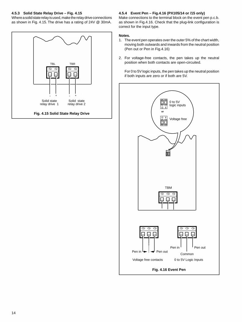
4.5.3 Solid State Relay Drive – Fig. 4.15Where a solid state relay is used, make the relay drive connectionsas shown in Fig. 4.15. The drive has a rating of 24V @ 30mA.
4.5.4 Event Pen – Fig.4.16 (PX105/14 or /15 only)Make connections to the terminal block on the event pen p.c.b.as shown in Fig.4.16. Check that the plug-link configuration iscorrect for the input type.
Notes.1. The event pen operates over the outer 5% of the chart width,
moving both outwards and inwards from the neutral position(Pen out or Pen in Fig.4.16)
2. For voltage-free contacts, the pen takes up the neutralposition when both contacts are open-circuited.
For 0 to 5V logic inputs, the pen takes up the neutral positionif both inputs are zero or if both are 5V.
Fig. 4.15 Solid State Relay Drive
Fig. 4.16 Event Pen

15
TB1EARTH
AV1
N L L NMAINS OUTPUT MAINS INPUT
Line
Neutral
Earth
315mAType T
(anti-surge)
Link 1
110V
230V
110V
1
2230V
TB1EARTH
AV1
– + INPUT
Earth
+–
5AType T(anti-surge)
4.6 Power Supply4.6.1 Mains Input Voltage Connections – Fig. 4.17Unscrew the captive knurled fixing screw and remove theprotective cover to the extent of the attached earthing cable (seeFig. 4.1).
Connect the mains power cables as shown in Fig. 4.17. Securelyconnect the power earth cable to the earth terminal stud fitted tothe recorder case. To select the mains input voltage refer toSection 4.6.2, following.
Refit the protective cover, ensuring that the earthing cable issecurely attached and is within the cover after securing.
4.6.2 Selecting the Mains Input Voltage – Fig. 4.18The mains input voltage (110V or 230V) is selected by re-positioning a plug-in 'handbag' link on the power supply p.c.b.
1 Identify the link.
2 Position the link for the mains supply voltage used.
4.6.3 D.C. Supply – Fig.4.19D.C. powered instruments accept a 10 to 30V d.c. supply. Makeconnections as shown in Fig.4.19.
Fig. 4.17 Mains Input
Fig. 4.19 D.C. Supply Connections
Fig. 4.18 Selecting the Mains Input Voltage

16
1 23 =
Enter
1 23 =
Enter
Channel 1Alarm L.E.D.s
Channel 3Alarm L.E.D.s
Channel 2Alarm L.E.D.s
'Pen Lift'Switch
20-characterDisplay
'Channel'Switch
'DecimalPoint'Switch
'Raise'Switch
'PageAdvance'
Switch
'ParameterAdvance'
Switch
'Lower'Switch
'Enter'Switch
1 2 3Channel
Broken SensorSymbol
5 FAMILIARISATION WITH CONTROLS, DISPLAYAND L.E.D. INDICATION
The tactile membrane switches, display and alarm l.e.d.s arelocated above the chart. Open the door for access to thesecontrols.
5.1 Controls – Fig. 5.1The controls comprise tactile membrane switches requiring onlymoderate finger pressure for operation.
'Pen Lift' switch – Used to raise and lower the pens onalternate operations. All the pens move to an automaticreferencing position just outside full scale on the chartwhen raised using the 'Pen Lift' switch.
Note. If the 'Pen Lift' switch is not pressed to lower thepens, the pens automatically return to their operatingpositions after a five minute delay.
'Channel' switch – used to select the channel, orcommon settings, to be programmed (see Fig. 8.2 onpage 23).
'Page Advance' switch – used to advance to the nextprogram page (see Fig. 8.2 on page 23).
'Parameter Advance' switch – used for advancing tothe next parameter within a program page or, if inOperating Page 1 (Section 7), for stopping automaticparameter advancement, i.e. for viewing individualmeasured values.
'Raise' switch – used for increasing a parametervalue or stepping-up through a selection of parameters(see Note 1).
'Lower' switch – used for decreasing a parametervalue or stepping-down through a selection ofparameters (see Note 1).
'Decimal point' switch – used to adjust the decimalpoint position during programming of certainparameters.
'Enter' switch – used for storing the programmedfunction parameters and values into the instrument'snon-volatile memory (see Note 2).
Notes.1. Continued pressure on the 'Raise' and 'Lower' switches
causes the rate of change of the displayed value to increase.To make small adjustments press the switches momentarily.Operation of the 'Raise' and 'Lower' switches duringprogramming causes the value or parameter being changedto flash until the 'Enter' switch is pressed. If left flashing forapproximately five minutes the display reverts to its originalvalue.
2. The 'Enter' switch must be operated each time a parameteror value is changed otherwise, on advancing to the nextparameter, the value reverts to that originally displayed.
5.2 Display – Fig.5.1A 20-character 5 x 7 dot-matrix, blue-filtered, vacuum fluorescentdisplay is used for display of all operating and programmingparameters.
5.2.1 Broken SensorThe position of broken sensor symbols on the display identifiesthe channel affected – see Fig. 5.1.
5.3 Alarm L.E.D. Indication – Fig. 5.1Alarm states are indicated by a vertical pair of red/green l.e.d.sfor each pen.
Fig. 5.1 Control Panel

17
1
3
2
5
6
4
6 SETTING UP
6.1 Recorder Start-upCAUTION. Ensure that all connections, especially to the earthstud, are made correctly.
Check that:a) The input sensors are correctly installed.
b) The red pen tip coincides with the correct time line on thechart – see step 5 below. (To avoid collision the green penwrites approximately 4mm ahead of the red pen and the bluepen writes approximately 4mm behind the red pen, withrespect to time.)
Note. Only the red pen can follow precisely the time line onthe chart, since the other pen traces are at different radii fromthe common pivot. On instruments fitted with an event penthe event marker draws on the same time line as the red pen.
Switch on the supply to the instrument, any power-operatedcontrol circuits and the input signals and wait for the pens tosettle. (Pen lifting, referencing and lowering occur automaticallywhen the power is first switched on.) 'TEST IN PROGRESS' isdisplayed for approximately five seconds to allow for internalreferencing. The recorder then reverts to a display of themeasured value(s) – see Section 7.1.
6.2 Fitting the Chart – Fig. 6.1Ensure the power supply is on.
1 Press the 'Pen Lift' switch.
2 Lift the chart clamp and remove the old chart, if the recorderis already in use.
3 Fit the new chart on to the spindle, ensuring that it is beneathall the pen lifter arms.
4 Locate the lower edges of the chart in the retaining slots andthe upper edge under the control panel.
5 Rotate the chart on the spindle until it is positioned for correcttime recording by the red pen. Use the marker on the chassisas a guide only.
6 Lower the chart clamp and press on it firmly to ensure that thetwo locating pins pierce the paper.
If the instrument is already in use press the pen 'Raise/Lower'switch, otherwise proceed to Section 7.
Fig. 6.1 Fitting the Chart

18
1
3
2
5
4
6.3 Fitting the Pen Capsule(s) – Fig. 6.2
With the power supply to the instrument turned on operate the'Pen Lift' switch – see Fig. 5.1.
With reference to Fig. 6.2:
1 Gently pull each individual pen arm down off the bracket,taking care not to bend the arms.
2 Remove the spent capsule by sliding it up the pen arm.
3 Fit a new capsule to the arm by sliding the 'dove-tail' on thecapsule into the slot in the pen arm. Pen arms are identifiedby the coloured mouldings at the top of each arm; red (No.1 pen), green (No. 2 pen), and blue (No. 3 pen). Theappropriate coloured ink capsule must be used.
4 Hold the new pen capsule and gently twist and pull the capfrom the pen fibre tip.
5 Slide the pen arm and capsule assembly on to the appropriatepen arm bracket until it clips into place, ensuring that eacharm is positioned just above its own pen lifter bar. The greenpen arm fits the pen arm bracket adjacent to the chart, the redpen arm fits the central bracket and the blue pen arm fits theupper bracket.
Press the 'Pen Lift' switch to lower the pens, and ensure that thepens make contact with the chart and, on multi-pen instruments,that they do not collide when the pen lifter is operated and thepens traverse the chart. If collision occurs the pen arms havebeen bent, or fitted incorrectly, and this damage must be carefullyrectified.
Fig. 6.2 Fitting the Pen Capsules

19
ALARM VALUES
SETPOINT VALUES
Standard alarm configuration –see Fig. 8.2.
Programmable alarm configuration– see Fig. 8.2.
or
At any time
1 # (Measured Value)
Display
Automatic Sequencing Manual Sequencing
ALARM VALUES
SETPOINT VALUES
Standard alarm configuration –see Fig. 8.2.
Programmable alarm configuration– see Fig. 8.2.
or
1 # (Measured Value)
2 # (Measured Value)
1 # (Measured Value)
2 # (Measured Value) At any timeduringAutomaticor ManualSequencing
1 #
7 OPERATION
In normal operation the measured values for all channels are displayed in an 'auto-advancing' sequence (Operating Page 1). Eachparameter can be held for viewing by operating the 'Parameter Advance' switch – see Fig. 5.1.
Operating the 'Page Advance' switch selects a second Operating Page (Operating Page 2) for viewing or changing the alarm setpoints. Required changes to the set point values are made using the 'Raise' and 'Lower' switches see Fig. 5.1.
A further series of pages can be selected using the 'Channel' and 'Page Advance' switches if the Security Link is enabled – see Figs.5.1, 8.1 and 8.2 on pages 16, 22 and 23.
Fig. 7.1 Operating Page 1, Single Pen Instruments
Fig. 7.2 Operating Page 1, Two-pen Instruments

20
ALARM VALUES
SETPOINT VALUES
Standard alarm configuration –see Fig. 8.2.
Programmable alarm configuration– see Fig. 8.2.
or
Automatic Sequencing Manual Sequencing
At any timeduringAutomaticor ManualSequencing
1 # (Measured Value)
2 # (Measured Value)
1 # (Measured Value)
2 # (Measured Value)
3 # (Measured Value) 3 # (Measured Value)
Alarm 1Set the value at which the alarm is to operate. Units displayedwill be those related to the channel to which the respectivealarm has been allocated in the ALARM SET UP page – seeFig. 8.2.
Alarm 6Repeat as above for AL2 to AL6 as required.
AL6 – – – –
Store.
Advance to next parameter.
Store.
Return to top of Operating Page 2
Where ALARM CONFIG PROG has been selected in thePROG COMMON SETTINGS page (Fig. 8.2) then AL1 to AL6is displayed.
Advance to next parameter or return to top of Operating Page 1.
N.B. To return to the top of Operating Page 1 at any time,operate the 'Page Advance' switch
Advance to Operating Page 2.
1 # – – – – –
2 # – – – – –
3 # – – – – –
Enter
Enter
AL1 – – – –
ALARM VALUES
Operating Page 1
or
Operating Page 2
7.1 Operating Page 17.2 Operating Page 27.2.1 Programmable Options
Fig. 7.3 Operating Page 1, Three-pen Instruments

21
1 High Alarm Set PointSet the high level alarm value for channel 1.
1 Low Alarm Set PointSet the low level alarm value for channel 1.
2 High Alarm Set PointSet the high level alarm value for channel 2.
2 Low Alarm Set PointSet the low level alarm value for channel 2.
3 High Alarm Set PointSet the high level alarm value for channel 3.
3 Low Alarm Set PointSet the low level alarm value for channel 3.
1 Lo SP – – – –
2 Hi SP – – – –
2 Lo SP – – – –
3 Hi SP – – – –
Advance to next parameter or return to top of Operating Page 1.
N.B. To return to the top of Operating Page 1 at any time,operate the 'Page Advance' switch
Store.
Advance to next parameter.
Store.
SET POINT VALUES
Advance to Operating Page 2.
Advance to next parameter.
Store.
Advance to next parameter.
Store.
Advance to next parameter.
Store.
Advance to next parameter.
Store.
Return to top of Operating Page 2.
Where ALARM CONFIG STD has been selected in the PROGCOMMON SETTINGS page then Hi / Lo SP for each channelis displayed.
3 Lo SP – – – –
1 Hi SP – – – –
3 # – – – – –
2 # – – – – –
1 # – – – – –
Enter
Enter
Enter
Enter
Enter
Enter
or
Operating Page 1
Operating Page 2
7.2.2 Standard Options

22
1363 1363
or
Disable
Enable
1
2
8 PROGRAMMING
8.1 Programming, Generala) When changing the input type it may be necessary to
reposition the input type selection links accordingly – seeSection 4.3.1.
b) Ensure that programming is enabled – see Section 8.2.
8.2 Program Security Link – Fig. 8.1A plug-in link is used to prevent unauthorised programming ofthe instrument, by preventing access to the Programming Pages– see Fig. 8.2.
With reference to Fig. 8.1:
1 Identify the link.
2 Enable or disable the Program Pages, as required.
With programming disabled any operation of the 'Channel'switch initiates 'PROGRAM DISABLED' to be displayed for a fewseconds.
8.3 To Change the Program, PreparationOpen the door, release the chassis and swing it forward – seeFig. 2.1.
Ensure that:
a) Input links are correctly positioned – see Fig. 4.2 (or Fig. 4.9for isolated inputs).
b) External alarm/control circuits are isolated if inadvertentoperation during programming is undesirable.
Any changes to the operating parameters are made using the'Raise', 'Lower', 'Decimal Point' and 'Enter', switches see Fig.5.1.
Carry out all programming, other than calibration (see Section10) with the pens lifted. If the pens drop during programming,operate the 'Pen Lift' switch – see Fig. 5.1.
When programming is complete disable the Programming Pages(Section 8.2) and recalibrate the instrument, see Section 10.
Fig. 8.1 Setting the Program Security Link

23
Op
erat
ing
Pag
e 1
Op
erat
ing
Pag
e 2
Co
mm
on
Pag
es
Pro
gra
mm
ing
Pag
es
SE
TP
OIN
T V
ALU
ES
1 H
i S
P
1 L
o S
P
2 H
i S
P
2 L
o S
P
3 L
o S
P
3 H
i S
P
SE
T U
P I
NP
UT
X
X I
NP
UT
TY
PE
X L
INE
AR
ISE
R
X L
INE
AR
UN
ITS
X L
INE
AR
FS
X R
AN
GE
FS
X L
INE
AR
ZE
RO
X R
AN
GE
ZE
RO
X I
NP
UT
FIL
TE
R
X B
RS
PR
OT
EC
T
SE
T U
P D
ISP
LAY
X
X D
ISP
LAY
FS
X D
ISP
LAY
ZE
RO
X S
ET
UN
ITS
S
TD
X U
NIT
S
ALA
RM
IND
ICA
TIO
N X
X H
i SP
BE
LOW
- -
- -
X L
o S
P A
BO
VE
- -
- -
X L
o S
P B
ELO
W-
- -
-
X H
i SP
AB
OV
E
- -
- -
INP
UT
& R
EC
OR
D C
ON
D
CH
AR
T T
IME
RE
JEC
TIO
N F
RE
Q
PR
OG
CO
MM
ON
SE
TT
ING
SP
RO
G C
OM
MO
N S
ET
TIN
GS
PR
OG
CO
MM
ON
SE
TT
ING
S
PR
OG
RA
MM
E C
HA
NN
EL
3
PR
OG
RA
MM
E C
HA
NN
EL
3P
RO
GR
AM
ME
CH
AN
NE
L 2
PR
OG
RA
MM
E C
HA
NN
EL
1
1 #
3 #
2 #
Ref
er t
o p
age
31R
efer
to
pag
e 31
SE
T U
P M
OD
ULE
PO
SN
1 to
3
MO
D T
YP
E
MO
D R
L 1
AC
T
MO
D R
L 1
ALL
OC
MO
D R
L 2
AC
T
MO
D R
L 2
ALL
OC
Ref
er t
o p
age
33
Ref
er t
o p
age
25R
efer
to
pag
e 27
Ref
er t
o p
age
30
Ref
er t
o p
age
21R
efer
to
pag
e 19
Ref
er t
o p
age
39
ALA
RM
VA
LUE
S
AL
1
AL
2
AL
3
AL
4
AL
6
AL
5Ref
er t
o p
age
20
AL1
CH
AN
ALL
OC
AL1
AB
OV
E
AL1
BE
LOW
ALA
RM
CO
NF
IG P
RO
G
or
Sta
ndar
dA
larm
Con
figur
atio
n–
refe
r to
'ALA
RM
SE
TU
P p
age'
Pro
gram
mab
leA
larm
Con
figur
atio
n–
refe
r to
'ALA
RM
SE
TU
P p
age'
Key
:
Sta
ndar
d al
arm
conf
igur
atio
n on
ly
or
X C
HA
R 2
X C
HA
R 1
X C
HA
R 3
X C
HA
R 5
X C
HA
R 4
X C
HA
R 6
X S
ET
UN
ITS
P
RO
G
or
Pag
e om
itted
if P
rogr
amm
able
Ala
rm C
onfig
urat
ion
is u
sed
– re
fer
to 'A
LAR
M S
ET
UP
pag
e'
on a
ltern
ate
oper
atio
ns
CA
LIB
RA
TE
CH
AN
NE
L X
X A
PP
LY Z
ER
O IN
PU
T
X Z
ER
O A
CC
EP
TE
D
X A
PP
LY F
S IN
PU
T
X C
ALI
BR
AT
E (
Y/N
)
X F
S A
CC
EP
TE
D
Dis
play
s w
ill c
hang
e if
inco
rrec
tin
puts
are
app
lied
* **
* O
nly
incl
uded
for
tem
pera
ture
line
aris
ers
** O
mitt
ed fo
r te
mpe
ratu
re in
put t
ype
with
rele
vant
tem
pera
ture
line
aris
er
Pro
gram
mab
leA
larm
Con
figur
atio
non
ly
AL6
AB
OV
E
AL6
BE
LOW
AL6
CH
AN
ALL
OC
Ref
er t
op
age
24
Ref
er t
o p
age
34
SE
T U
P M
OD
ULE
PO
SN
4 to
6
MO
D T
YP
E
MO
D R
L 1
AC
T
MO
D R
L 1
ALL
OC
MO
D R
L 2
AC
T
MO
D R
Tx
FS
MO
D R
L 2
ALL
OC
MO
D R
Tx
ZE
RO
MO
D R
Tx
ALL
OC
SE
T U
P R
Tx
OU
TP
UT
MO
D M
IN O
/P
MO
D M
AX
O/P
or
SE
T U
P M
OD
ULE
PO
SN
X
MO
D X
TY
PE
E
VE
NT
*
* A
vaila
ble
on m
odul
e po
sitio
ns 2
or
3w
hen
fitte
d w
ith E
vent
Pen
mod
ule
or
ALA
RM
SE
T U
P
ALA
RM
CO
NF
IG S
TD
3 =
1 2
3 =
1 2
3 =
1 2
3 =
1 2
3 =
1 2
X C
ALI
BR
AT
E (
A/M
)
X C
AL
PE
N F
S
X C
AL
PE
N Z
ER
O
X C
AL
ZE
RO
X C
AL
FS
Aut
omat
ic
Man
ual
Fig. 8.2 Overall Programme Chart

24
1 # xxxxx
2 # xxxxx
3 # xxxxx
Program Channel 2
Program Channel 1PROGRAM CHANNEL 1
Advance to next parameter.
Advance to next parameter to program channel 1.
Advance to program channel 2.
Advance to next parameter to program channel 2.
Advance to program channel 3.
or
PROGRAM CHANNEL 2
or
Advance to program common settings.
Program Channel 3
Program Common Settings
Advance to next parameter to program common settings.
PROGRAM CHANNEL 3
PROG COMMON SETTINGS
Advance to next parameter to program channel 3.
Return to top of Operating Page 1.
or
or
Operating Page 1Automatic sequencing display of measured values for allchannels – see Section 7.1.
3 =1 2
3 =1 2
3 =1 2
3 =1 2
3 =1 2
8.4 Access to Programming Pages
8.5 Set Up Input PageThe intrinsic error for zero based ranges is ≤0.25% if the limitsdetailed in Tables 3 and 4 are observed. If a suppressed zerorange is used the error could exceed this figure.
Table 2 Electrical Limits
Table 3 Temperature Limits
epyTtupnI)lacirtcelE(
tratS.niM napS.niMdnanapS.xaM
eulaVegnaR
stlovilliMstloV
spmailliMecnatsiseR
999–0.02–9.99–
0.02
00.505.005.00.02
00010.020.0010002
)stupnIerutarepmeT(epyTtupnI° edargitneC ° tiehnerhaF
.pmeTtratS.niM napS.niM .pmeT.xaM .pmeTtratS.niM napS.niM .pmeT.xaM
:selpuocomrehT
485CEIdnaJepytSB,noC/eF 001– 001 009 841– 081 2561
Lepyt01734NID,noC/eF 001– 001 009 841– 081 2561
485CEIdnaKepytSB,lAiN/rCiN 001– 051 0031 841– 072 2732
485CEIdnaS&RsepytSB,hRtP/tP 81– 006 0071 0 0801 2903
485CEIdnaTepytSB,iNuC/uC 052– *)ev+(021 003 814– *)ev+(612 275
**)ev–(071 **)ev–(603
485CEIdnaEepytSB,iNuC/rCiN 001– 001 009 841– 081 2561
485CEIdnaBepytSB,hR%6tP/hR%03tP 81– 0011 0081 0 0891 2723
NepytSB,iSiN/iSrCiN 002– )ev+(081 0031 823– )ev+(423 2732
)4091SB(001tP,retemomrehTecnatsiseR 002– 05 006 823– 09 2111
orezevobasegnarrofnapsmuminiM*orezwolebsegnarrofnapsmuminiM**

25
Input TypeEnsure that the Input links are in the correct positions for therequired input type for the channel (see Fig. 4.2 or Fig. 4.9).
Apply an input signal appropriate to (or compatible with) theinput type selected and having an approximate mid-scale valueof the range to be programmed below.
Select the required input. The display flashes until the 'Enter'
LineariserSelect the required lineariser, or NONE, to suit the appliedinput.
Lineariser UnitsSelect either °C or °F as required.
Note: If Lineariser Type L has been selected only °C is
SET UP INPUT X
X LINEARISER PWR 5/2
PWR 3/2
SQ ROOTRT
TYPE L
TYPE T
TYPE S
TYPE K
NONE
TYPE N
TYPE B
TYPE R
TYPE J
TC
RTD
ΩV
mA
mV
X INPUT TYPE
°F
X LINEAR UNITS °C
Store.
Advance to next parameter.
Advance to next parameter.
Store.
Advance to next parameter.
Store.
Advance to next parameter.
PWR 5/2
PWR 3/2
SQ ROOT
NONE
PWR 5/2
PWR 3/2
SQ ROOT
NONE
Continued overleaf
Enter
Enter
Enter
(a) (b)
(c)
8.5 Set Up Input Page (continued)

26
Lineariser Full ScaleSet the range maximum temperature in °C or °F as selected atLINEAR UNITS on the previous page within the limits
Lineariser ZeroSet the range minimum temperature in °C or °F as selected atLINEAR UNITS on the previous page within the limits
Range Full ScaleSet the highest range value to the maximum number of decimalplaces possible, e.g. 20.0 instead of 20. For instruments fitted
Range ZeroSet the lowest range value – the decimal point is set
Broken Sensor ProtectionSelect the broken sensor protection indication to ‘UP’ forupscale, ‘DOWN’ for downscale or to ‘NONE’. In the event of abroken sensor occurring the pen will move as programmed up-
Input FilterIf the input is noisy it may be necessary to modify theinstrument response to fast signals. Filter time is programmablefrom 0 to 60s in 1s steps. The value to be entered must be
X RANGE ZERO XXXX
X LINEAR ZERO XXXX
X RANGE FS XXXX
X INPUT FILTER XXs
X BRS PROTECT UP
DOWNNONE
Store.
Advance to next parameter.
Store.
Advance to next parameter.
Store.
Advance to next parameter.
Store.
Advance to next parameter.
Store.
Advance to next parameter.
Store.
Return to top of Set Up Input page.
X LINEAR FS XXXX
RT
TYPE L
TYPE T
TYPE S
TYPE K
TYPE N
TYPE B
TYPE R
TYPE JTC
RT
Continued from previous page
and
Enter
Enter
Enter
Enter
Enter
Enter
(a) (b) (c)
and

27
Display Full ScaleSet the required display value represented by the maximuminput signal.Example. If a 2.02 to 7.34 mV input represents a temperaturerange of 50 to 180°C set 180.0. Available adjustment range–999 to 3300.
Display ZeroSet the value for the variable represented by the minimum inputsignal.Example. From the above set 50.0. The decimal point is set
Set UnitsSelect ‘PROG’ to customise a six-digit unit of measurement,
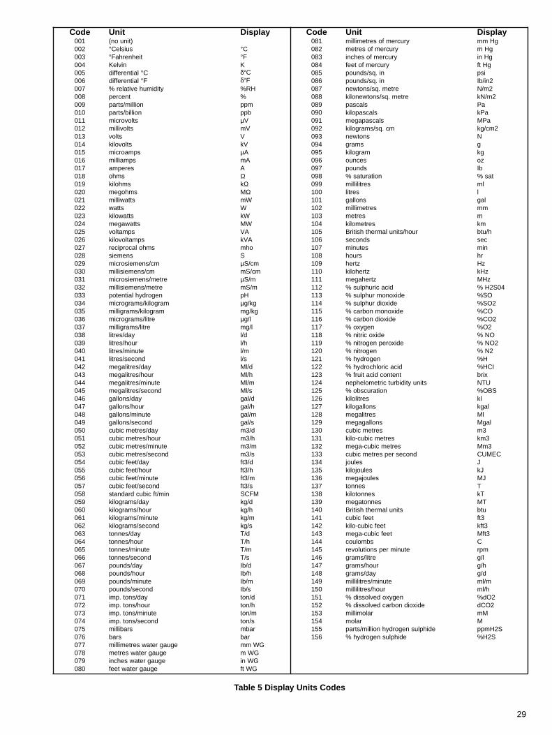
UnitsSet the code number selected from Table 6, corresponding tothe required display units. The actual display units are visually
Character 1Set the code number corresponding to the first character of thecustomised six-digit unit of measurement selected from the
X DISPLAY ZERO XXXX
X UNITS °C 002
SET UP DISPLAY X
X DISPLAY FS XXXX
X CHAR 1 % 063
X SET UNITS
PROGSTD
Advance to next parameter.
Advance to next parameter.
Advance to next parameter.
PROG
Advance to next parameter.
Store.
Store.
Store.
Store.
Store.
Advance to next parameter.
Advance to next parameter.
STD
Continued overleaf
Enter
Enter
Enter
Enter
Enter
(a) (b)
and
8.6 Set Up Display Page

28
Character 2Repeat the previous step for the second character.
Character 6Select characters 3 to 6 by the same method.
X CHAR 2 %N 014
X CHAR 6 %NH4OH 008
Store.
Store.
Return to top of Set Up Display page.
Advance to next parameter.
Continued from previous page
Enter
Enter
(a) (b)
Table 4 Character Set
edoC lobmyS edoC lobmyS edoC lobmyS edoC lobmyS edoC lobmyS
000 ecapS 020 T 040 n 060 7 080 ∑100 A 120 U 140 o 160 8 180 µ200 B 220 V 240 p 260 9 280 ø300 C 320 W 340 q 360 % 380 ö400 D 420 X 440 r 460 & 480 Å500 E 520 Y 540 s 560 , 580 π600 F 620 Z 640 t 660 - 680 θ700 G 720 a 740 u 760 : 780 °800 H 820 b 840 v 860 # 880 2m900 I 920 c 940 w 960 \ 980 3m010 J 030 d 050 x 070 / 090 2S110 K 130 e 150 y 170 . 190 2210 L 230 f 250 z 270 ~ 290 3310 M 330 g 350 0 370 = 390 4410 N 430 h 450 1 470 α 490 5510 0 530 i 550 2 570 ß 590 6610 P 630 j 650 3 670 ∆ 690 2710 Q 730 k 750 4 770 δ 790 3810 R 830 l 850 5 870 Ω 890 4910 S 930 m 950 6 970 ρ 990 ni
29
Table 5 Display Units Codes
edoC tinU yalpsiD edoC tinU yalpsiD100 )tinuon( 180 yrucremfosertemillim gHmm200 ° suisleC °C 280 yrucremfosertem gHm300 ° tiehnerhaF °F 380 yrucremfosehcni gHni400 nivleK K 480 yrucremfoteef gHtf500 laitnereffid °C δ°C 580 ni.qs/sdnuop isp600 laitnereffid °F δ°F 680 ni.qs/sdnuop 2ni/bI700 ytidimuhevitaler% HR% 780 ertem.qs/snotwen 2m/N800 tnecrep % 880 ertem.qs/snotwenolik 2m/Nk900 noillim/strap mpp 980 slacsap aP010 noillib/strap bpp 090 slacsapolik aPk110 stlovorcim µV 190 slacsapagem aPM210 stlovillim Vm 290 mc.qs/smargolik 2mc/gk310 stlov V 390 snotwen N410 stlovolik Vk 490 smarg g510 spmaorcim µA 590 margolik gk610 spmaillim Am 690 secnuo zo710 serepma A 790 sdnuop bI810 smho Ω 890 noitarutas% tas%910 smholik kΩ 990 sertilillim lm020 smhogem MΩ 001 sertil l120 sttawillim Wm 101 snollag lag220 sttaw W 201 sertemillim mm320 sttawolik Wk 301 sertem m420 sttawagem WM 401 sertemolik mk520 spmatlov AV 501 ruoh/stinulamrehthsitirB h/utb620 spmatlovolik AVk 601 sdnoces ces720 smholacorpicer ohm 701 setunim nim820 snemeis S 801 sruoh rh920 mc/snemeisorcim µ mc/S 901 ztreh zH030 mc/snemeisillim mc/Sm 011 ztreholik zHk130 ertem/snemeisorcim µ m/S 111 ztrehagem zHM230 ertem/snemeisillim m/Sm 211 dicaciruhplus% 40S2H%330 negordyhlaitnetop Hp 311 edixonomruhplus% OS%430 margolik/smargorcim µ gk/g 411 edixoidruhplus% 2OS%530 margolik/smargillim gk/gm 511 edixonomnobrac% OC%630 ertil/smargorcim µ l/g 611 edixoidnobrac% 2OC%730 ertil/smargillim l/gm 711 negyxo% 2O%830 yad/sertil d/l 811 edixocirtin% ON%930 ruoh/sertil h/l 911 edixorepnegortin% 2ON%040 etunim/sertil m/l 021 negortin% 2N%140 dnoces/sertil s/l 121 negordyh% H%240 yad/sertilagem d/lM 221 dicacirolhcordyh% ICH%340 ruoh/sertilagem h/lM 321 tnetnocdicatiurf% xirb440 etunim/sertilagem m/lM 421 stinuytidibrutcirtemolehpen UTN540 dnoces/sertilagem s/lM 521 noitarucsbo% SBO%640 yad/snollag d/lag 621 sertilolik lk740 ruoh/snollag h/lag 721 snollagolik lagk840 etunim/snollag m/lag 821 sertilagem lM940 dnoces/snollag s/lag 921 snollagagem lagM050 yad/sertemcibuc d/3m 031 sertemcibuc 3m150 ruoh/sertemcibuc h/3m 131 sertemcibuc-olik 3mk250 etunim/sertemcibuc m/3m 231 sertemcibuc-agem 3mM350 dnoces/sertemcibuc s/3m 331 dnocesrepsertemcibuc CEMUC450 yad/teefcibuc d/3tf 431 seluoj J550 ruoh/teefcibuc h/3tf 531 seluojolik Jk650 etunim/teefcibuc m/3tf 631 seluojagem JM750 dnoces/teefcibuc s/3tf 731 sennot T850 nim/tfcibucdradnats MFCS 831 sennotolik Tk950 yad/smargolik d/gk 931 sennotagem TM060 ruoh/smargolik h/gk 041 stinulamrehthsitirB utb160 etunim/smargolik m/gk 141 teefcibuc 3tf260 dnoces/smargolik s/gk 241 teefcibuc-olik 3tfk360 yad/sennot d/T 341 teefcibuc-agem 3tfM460 ruoh/sennot h/T 441 sbmoluoc C560 etunim/sennot m/T 541 etunimrepsnoitulover mpr660 dnoces/sennot s/T 641 ertil/smarg l/g760 yad/sdnuop d/bI 741 ruoh/smarg h/g860 ruoh/sdnuop h/bI 841 yad/smarg d/g960 etunim/sdnuop m/bI 941 etunim/sertilillim m/lm070 dnoces/sdnuop s/bI 051 ruoh/sertilillim h/lm170 yad/snot.pmi d/not 151 negyxodevlossid% 2Od%270 ruoh/snot.pmi h/not 251 edixoidnobracdevlossid% 2OCd370 etunim/snot.pmi m/not 351 ralomillim Mm470 dnoces/snot.pmi s/not 451 ralom M570 srabillim rabm 551 edihplusnegordyhnoillim/strap S2Hmpp670 srab rab 651 edihplusnegordyh% S2H%770 eguagretawsertemillim GWmm870 eguagretawsertem GWm970 eguagretawsehcni GWni080 eguagretawteef GWtf

30
Alarm Indication page is not displayed when ‘ALARMCONFIG PROG’ in ‘ALARM SET UP’ page on the ‘PROG
High Alarm Set Point AboveSelect the colour of l.e.d. to be illuminated above the high set
High Alarm Set Point BelowSelect the colour of l.e.d. to be illuminated below the high set
Low Alarm Set Point AboveSelect the colour of l.e.d. to be illuminated above the low set
Low Alarm Set Point BelowSelect the colour of l.e.d. to be illuminated below the low set
ALARM INDICATION X
X HI SP ABOVE
RED
GREEN
OFF
RED
X HI SP BELOW
GREEN
OFF
Store.
Advance to next parameter.
Advance to next parameter.
Store.
Store.
Advance to next parameter.
Store.
Advance to next parameter.
Return to top of Alarm Indication page.
Enter
Enter
Enter
Enter
X Lo SP ABOVE
RED
GREEN
OFF
X Lo SP BELOW
RED
GREEN
OFF
8.7 Alarm Indication Page

31
Chart TimeSet the chart speed in hours per revolution selected from the
Rejection FrequencyRejection Frequency eliminates interference at mains
INPUT & RECORD COND
CHART TIME: XXX h/rev
60 Hz
REJECTION FREQ 50 Hz
Advance to next parameter.
Store.
Advance to next parameter.
Store.
Return to top of Input and Recording Conditions page.
Enter
Enter
Alarm ConfigurationIf ‘ALARM CONFIG STD’ on the ‘ALARM SET UP’ page in the‘PROG COMMON SETTINGS’ page is selected then Hi SP /Lo SP for each channel is displayed. If ‘ALARM CONFIGPROG’ is selected then AL1 to AL6 is displayed.
Select STD if a standard alarm configuration of two alarms perchannel is required. Select PROG if more than two alarms per
Alarm 1 Channel Allocation
Select the channel number to which the alarm set point is to be
ALARM SET UP
ALARM CONFIG
PROG
STD
CH2
CH3
CH1
AL1 CHAN ALLOC
PROG
STD
Store.
Advance to next parameter.
Store.
Advance to next parameter.
Continued overleaf
Enter
Enter
(a) (b)
8.8 Calibration PageFor full calibration details refer to Section 10.
8.9 Input and Recording Conditions Page
8.10 Alarm Set Up Page

32
Advance to next parameter.
Alarm 1 Above
Alarm 1 BelowSelect the colour of l.e.d. to be illuminated below the set point.
Repeat the above steps for the remaining five alarm set
Store.
Advance to next parameter.
Store.
Advance to next parameter.
Store.
Advance to next parameter.
Store.
Advance to next parameter.
Store.
Return to top of Alarm Set Up page.
Continued from previous page
Enter
Enter
Enter
Enter
Enter
GREEN
RED
OFF
AL1 ABOVE
GREEN
RED
OFF
AL1 BELOW
AL6 CHAN ALLOC
CH2
CH3
CH1
AL6 ABOVEGREEN
RED
OFF
AL6 BELOW
GREEN
RED
OFF
(a) (b)

33
SET UP MODULE POSNX
or orMODX RL1 ALLOC Al 5+6
Al 1+2
Al 3+4
Set Up Module Position 1,2 and 3.Note. On single pen instruments no modules can be
Module Position 1,2 and 3, TypeSelect the module type fitted in module position1,2 or 3 – see Fig. 4.1.
* This module type is not available for module
Module Position 1,2 and 3, Relay 1 ActionSelect the relay 1 action required:
'3 ST OFF' – 3-state off between set points'3 ST ON' – 3-state on between set points'LAT EB' – latch below setpoints'LAT EA' – latch above setpoints'EB' – energised below setpoint'EA' – energised above setpoint.
See Section 12 for more detailed information onalarm set points.
Store.
Advance to next parameter.
Advance to next parameter.
Module Position 1,2 and 3, Relay 1 Allocation(Standard Alarm Configuration)For 'EA' or 'EB' alarm action:
Allocate the alarm to a high or low setpoint.For '3 ST OFF', '3 ST ON', 'LAT EB' or 'LAT EA':
Module Position 1,2 and 3, Relay 1 Allocation(Programmable Alarm Configuration)For 'EA' or 'EB' alarm action:
Allocate the relay to an alarm point.
For '3 ST OFF', '3 ST ON', 'LAT EB' or 'LAT EA':Allocate the relay to an alarm point pair.
PRESSURETX PSUNONE
1 RELAY2 RELAYS
EBEA LAT EA
LAT EB3 ST ON3 ST OFF
MODX TYPE 2 RELAYS
PRESSURE
TX PSU
NONE
1 RELAY
ISOL I/P
MODX RL1 ACT 3 ST OFF3 ST ON
LAT EA
LAT EB
EA
EB
MODX RL1 ALLOC CH 3
CH 1CH 2
CH 1
Al 1
MODX RL1 ALLOC Al 6
Al 2
Al 3
Al 4
Al 5
MODX RL1 ALLOC Lo 3
Lo 1
Hi 2
Lo 2
Hi 3
Hi 1
Store.
Advance to next parameter.
Store.
Advance to next parameter.
1 RELAY
2 RELAYS
Continued overleaf
Standard Alarm Configuration
Programmable Alarm Configuration
ISOL I/P
Enter
Enter
Enter
*
(a) (b)
8.11 Set Up Module Page8.11.1 Module Positions 1,2 and 3

34
Store.
Advance to next parameter.
MODX RL2 ACT 3 ST OFF
3 ST ON
LAT EB
LAT EAEB
EA
Hi 1
oror
MODX RL2 ALLOC Al 5+6
Al 1+2
Al 3+4
Al 1
Al 2
Al 3
Al 4
Al 5
MODX RL2 ALLOC Al 6
Store.
Return to top of Set Up Module page.
Module Position 1,2,3, Relay 2 ActionRepeat as for Module Position 1,2,3, Relay 1
Module Position 1,2,3, Relay 2 Allocation(Standard Alarm Configuration)Repeat as for Module Position 1,2,3, Relay 1Allocation (Standard Alarm Configuration), on
Module Position 1,2,3, Relay 2 Allocation(Programmable Alarm Configuration)Repeat as for Module Position 1,2,3,Relay 1 Allocation (Programmable Alarm
Continued from previous page
Standard Alarm Configuration
Programmable Alarm Configuration
-
Enter
Enter
or
or
or
or
CH 1CH 2
MODX RL2 ALLOC CH 3
Lo 1
Hi 2
Lo 2
Hi 3
MODX RL2 ALLOC Lo 3
(a) (b)
SET UP MODULE POSNX Set Up Module Position 4,5 and 6.
Module Position 4,5 and 6, TypeSelect the module type fitted in module position
Store.
Advance to next parameter.
TX PSU
NONE
1 RELAY
RTx2 RELAYS
RTx+RLYMODX TYPE
Continued opposite
Enter
(a) (b)
8.11.2 Module Positions 4, 5 and 6

35
RTx
Advance to next parameter.
or or
Module Position 4,5,6, Relay 2 Allocation(Standard Alarm Configuration)For 'EA' or 'EB' alarm action:
Allocate the alarm to a high or low setpoint.
For '3 ST OFF', '3 ST ON', 'LAT EB' or 'LATEA':
Allocate the relay to a channel.
Advance to next parameter.
Module Position 4,5,6, Relay 1 ActionSelect the relay 1 action required:
'3 ST OFF' – 3-state off between set points'3 ST ON' – 3-state on between set points'LAT EB' – latch below setpoints'LAT EA' – latch above setpoints'EB' – energised below setpoint'EA' – energised above setpoint.
Store.
or orMODX RL1 ALLOC Al 5+6
Al 1+2
Al 3+4
MODX RL1 ALLOC CH 3
Al 1
MODX RL1 ALLOC Al 6
Al 2
Al 3
Al 4
Al 5
1 RELAY RTx+RLY
Module Position 4,5,6, Relay 1 Allocation(Standard Alarm Configuration)For 'EA' or 'EB' alarm action:
Allocate the alarm to a high or low setpoint.
For '3 ST OFF', '3 ST ON', 'LAT EB' or 'LATEA':
Allocate the relay to a channel.
Module Position 4,5,6, Relay 1 Allocation(Programmable Alarm Configuration)For 'EA' or 'EB' alarm action:
Allocate the relay to an alarm point.
For '3 ST OFF', '3 ST ON', 'LAT EB' or 'LATEA':
Allocate the relay to an alarm point pair.
Note. Al 1 > Al 2, Al 3 > Al 4 and Al 5 > Al6.
Advance to next parameter.
Store.
Advance to next parameter.
MODX RL2 ACT 3 ST OFF
3 ST ON
LAT EA
LAT EB
EA
EB
2 RELAYs Module Position 4,5,6, Relay 2 ActionSelect the relay 2 action required:
'3 ST OFF' – 3-state off between setpoints'3 ST ON' – 3-state on between setpoints'LAT EB' – latch below setpoints'LAT EA' – latch above setpoints'EB' – energised below setpoint'EA' – energised above setpoint.
Store.
Continued from opposite page
Continued overleaf
Standard Alarm Configuration
Standard Alarm Configuration
Programmable Alarm Configuration
1 RELAY2 RELAYSRTx+RLY
TX PSUNONE
MODX RL1 ACT 3 ST OFF
3 ST ON
LAT EA
LAT EB
EAEB
LAT EALAT EB3 ST ON3 ST OFF
LAT EALAT EB3 ST ON3 ST OFF
EBEA
EBEA
MODX RL1 ALLOC Lo 3
Lo 1
Hi 2
Lo 2
Hi 3
Hi 1
CH 1CH 2
CH 1CH 2
MODX RL2 ALLOC CH 3
Lo 1Hi 2Lo 2Hi 3
Hi 1
Enter
Enter
Enter
(a) (b)
MODX RL2 ALLOC Lo 3
(a)(b)

36
MODX RTx FS 20.0mA10.0
SET UP RTx OUTPUT
MODX RTx ZERO 10.0mA00.0
Store.
Advance to next parameter.
Store.
Advance to next parameter.
Store.
Advance to next parameter.
Store.
Advance to next parameter.
Module Position 4,5,6,Retransmission FullScaleSet the maximum value required for theretransmission signal, adjustable in 0.1mA
Module Position 4,5,6,Retransmission ZeroSet the minimum value required for theretransmission signal, adjustable in 0.1mA
Module Position 4,5,6, RetransmissionAllocationSelect the channel to which the retransmissionsignal is to be allocated. *Control Set Point 1may be selected on recorders with PID facility.This parameter is not displayed for single
Module Position 4,5,6 RetransmissionMinimum OutputConnect a 0 to 20mA milliammeter to theappropriate module output connection andadjust the milliammeter displayed value tocoincide with the retransmission minimum
MODX RL2 ALLOC Al 5+6
Al 1+2Al 3+4
MOD X MIN O/P
Module Position 4,5,6, Relay 2 Allocation(Programmable Alarm Configuration)For 'EA' or 'EB' alarm action:
Allocate the relay to an alarm point.
For '3 ST OFF', '3 ST ON', 'LAT EB' or 'LATEA':
Allocate the relay to an alarm point pair. Note. Al 1 > Al 2, Al 3 > Al 4, Al 5 > Al 6.
Advance to next parameter.
Continued from previous page
Store.
Advance to next parameter.
Set Up Retransmission Output
Programmable Alarm Configuration
MODX RTx ALLOC CH 3
CH 2
CH 1
CSP 1 *
Enter
Enter
Enter
Enter
Enter
Al 1
MODX RL2 ALLOC Al 6
Al 2
Al 3
Al 4
Al 5
Continued opposite
(a) (b)
(a) (b)

37
Store.
Return to top of Set Up Module page.
Module Position 4,5,6, RetransmissionMaximum OutputAdjust the milliammeter displayed value tocoincide with the retransmission maximumsignal specified above.
Enter
Continued from previous page
MOD X MAX O/P
(a) (b)
SET UP MODULE POSN X
MOD X TYPE EVENT
Set up module position 2Set up module position 3
Advance to next parameter
Module 2 TypeModule 3 TypeThis display cannot be changed.
Return to top of Set Up Module page
8.11.4 Event Pen RangesIf a 1492 recorder with an event pen is using a standard chart, i. e. with a writing width of 105mm, the range and display full scalevalues for the variable pens must be set as described below:
Zero-based rangesOn the input page set Range Full Scale and/or Lineariser Full Scale to 96% of the full scale input value.On the Display page, set Display Full Scale to 96% of the variable represented by the full scale signal input.
Offset-zero rangesCalculate the Range Full Scale and Display Full Scale settings by using the actual input or display span values rather than fullscale; i.e. Range Full Scale would be 0.96 (input full scale – input min.) + input min.
Example. For an input of 4 to 20mA corresponding to a temperature range of 100 to 300°C from a type K thermocouple:
Lineariser Full Scale = 0.96 [300 – 100] + 100= 192 + 100= 292
Range Full Scale = mV equivalent of 292 – 100300 – 100 x 16 + 4
= 11.876 – 4.09512.207 – 4.095 x 16 + 4
= 7.7818.112 x 16 + 4
= 0.9592 x 16 + 4
= 15.35 + 4
= 19.35 mA
The above alternative setting procedures for Range Full Scale and Display Full Scale are not necessary if a chart with a writingwidth of 100mm is used.
8.11.3 Module Position 2 or 3 (Event Pen Module)

38
TBL TBR
NC C NO NC C NO
Arc suppression capacitors
Where second relay is fitted
IC2 IC4 IC1 IC3
9 SIMPLE FAULT FINDING
If the recorder does not appear to be working satisfactorily carryout the checks in the following table before contacting theService Organisation.
Are all the connections made correctly?
Is there power to the instrument?
Is there a signal at the input terminals?
Does an external relay fail to de-energise? If so see Section9.1, following.
9.1 Arc Suppression Capacitors – Fig. 9.1Arc suppression capacitors are fitted across the contacts of thealarm/control relays. If these contacts are used to operateexternal relays, the capacitor leakage current may be sufficientto prevent the external relay from de-energising. If so, switch offthe power supply and external alarm circuits. Identify theappropriate relay module – see Figs. 4.14a, 4.14b and 4.15b.Remove the four screws retaining the p.c.b. and carefullyunplug it.
CAUTION.The connection pins at the top of the p.c.b. are very fragile andcare must be taken not to bend or damage them.
Unsolder the appropriate capacitors as shown in Fig. 9.1 andrefit the module.
10 CALIBRATION
The recorder should be calibrated annually or following a changeto instrument operation. The pen arm length must be checked,and adjusted if necessary, before making any electricaladjustments.
10.1 Calibration, GeneralSwitch off the power supply. Connect the instrument to a signalsource or resistance box of known accuracy, suitable forsimulation over the entire input range, to the input terminals –see Section 4.3.
For thermocouple inputs, connect the millivolt sourceusing appropriate compensating cable – see Table 1.
For 2-lead resistance thermometers the resistance boxmay be connected at the sensor end of the leads or the leadresistance added to calibration values – see Section 10.3.
For all other inputs connect using copper wire.
Switch on the power supply.
10.2 Pen Arm Length AdjustmentIf the pen arm length is incorrect the pen does not record thecorrect time at all positions on the chart.
a) With reference to Fig. 8.2, select the Input and RecordingConditions Page, make a note of the Chart Time and thenreset it to 168hr/rev. Store using the 'Enter' switch.
b) Ensure that the pens are touching the chart and that the timeline marker on the chassis indicates the correct time line onthe chart – see Fig. 6.1.
c) Increase the channel 1 input signal from zero to full scale,within a period of 10 seconds, to draw an arc on the chart. Fortemperature inputs apply the equivalent millivolt or resistancevalues obtained from standard tables.
If the trace does not follow the time line the error must becorrected by adjusting the pen arm length as follows:
With reference to Fig. 9.2:1 Slacken the clamp screw.
2 Slide the pen arm in or out of the moulding, as necessary.
3 Retighten the clamp screw on completion.
Make similar adjustments to the green and blue pen arms, asapplicable. Ensure that the green pen records approximately4mm ahead of the red pen and the blue pen records approximately4mm behind the red pen (with respect to time) over the full chartwidth.
Note. Only the red pen can follow precisely the time line on thechart, since the radii of the other pens draw different loci. Oninstruments fitted with event marker the event pen draws on thesame time line as the red pen.
Reprogram the original chart time noted at a), above and storeusing the 'Enter' switch.
Fig. 9.1 Location of Arc Suppression Capacitors

39
1
3
2
CALIBRATE CHANNEL X
X CALIBRATE NO
YES
Advance to next parameter.
Advance to next parameter.
Store.
CalibrationSelect 'YES' to calibrate theinstrument.
NO
YES
Continued overleaf
Calibrate Channel
Enter
(a) (b)
X CALIBRATE AUTO
Enter
Calibration Mode (auto or manual)Select automatic calibration mode. For manual calibrationmode refer to Section 10.4 on page 42.
Advance to next parameter.
Store.
10.3 Calibration Page (Automatic Procedure)
Fig. 9.2 Pen Arm Length Adjustment

40
X APPLY ZERO INPUT
X APPLY ZERO INPUT
+X INPUT OUT OF RANGE
AlternatingDisplay
or
Apply Zero InputThe channel number flashes in this display until the correctinput signal is applied and the 'Enter' switch is operated.
Range Zero Calibration
Electrical Inputs:apply a signal equivalent to Input Range Zero.
Resistance thermometer Inputs:apply a signal input equivalent to Lineariser Zero usingresistance values obtained from standard tables. For 2-leadRTDs, ensure that the resistance source is either connected atthe sensor end of the leads or that the total lead resistance isadded to the value for range zero.
Thermocouple Inputs:measure the ambient temperature at the output terminals ofthe signal source (calibrator). From thermocouple tables obtainthe millivolt equivalent of this temperature (a) and that for theLineariser Zero temperature (b) – see page 26. Subtract (a)from (b) and set the signal source to the resultant value. (Thevoltage is negative if the range zero temperature is below themeasured ambient temperature).
Note. If the applied signal level is outside acceptable zerorange limits, the displayed message alternates between'APPLY ZERO INPUT' and 'INPUT OUT OF RANGE'. If sucha condition occurs check and reset the applied signal level.
Enter
X INPUT OUT OF RANGE
X APPLY FS INPUT
X ZERO ACCEPTED Zero InputThe applied input is within acceptable limits for zero calibration.
Store.
Range Full Scale CalibrationFor instruments with event pen see Section 8.11.4 on page 37.
Electrical Inputs:apply a signal equivalent to Input Range Full Scale.
Resistance thermometer Inputs:apply a signal input equivalent to Lineariser Full Scale usingresistance values obtained from standard tables. For 2-leadRTDs, ensure that the resistance source is either connected atthe sensor end of the leads or that the total lead resistance isadded to the value for range full scale.
Themocouple Inputs:apply an input (c) – (a) where (c) is the millivolt equivalent ofthe Lineariser Full Scale temperature obtained from standardtables.
Note. If the applied signal level is outside acceptable full scalerange limits, the displayed message alternates between'APPLY FS INPUT' and 'INPUT OUT OF RANGE'. If such acondition occurs check and reset the applied signal level.
Range Full Scale calibration, and hence the measured valuedisplayed during normal operation (see Operating Page 1), iscarried out automatically.
X APPLY FS INPUT
+ AlternatingDisplay
or
Continued from previous page
Enter
(a) (b)
Advance to next parameter.
Continued on opposite page
(a) (b)

41
CALIBRATING
CALIBRATED
START AUTOCAL NOYES
NO YES
Store.
Advance to next parameter.
'CALIBRATING' is displayed for a few seconds during theautomatic calibration procedure.
'CALIBRATED' is displayed on completion of the calibrationprocess.
Return to top of Calibration Page.
Automatic CalibrationSelect 'YES' to initiate automatic calibration.
Enter
Continued from previous page(a) (b)
Advance to next parameter.
X CAL PEN FS
Enter
The pen is automatically positioned at full scale. If there is anerror, i.e. pen not at full scale on the chart, ensure that thepen is touching the chart and use the 'Raise and Lower'switches to set pen full scale on the chart. For instrumentsfitted with event pen see Section 8.11.4 on page 37.
Pen Full Scale Calibration
or
Store.
Advance to next parameter.
X CAL PEN ZERO
Enter
The pen is automatically positioned at the zero position. Ifthere is an error, i.e. pen not at zero on the chart, ensure thatthe pen is touching the chart and use the 'Raise and Lower'switches to set pen zero on the chart.
Pen Zero Calibration
or
Store.
X FS ACCEPTED Full Scale InputThe applied input is within acceptable limits for full scalecalibration.
Store.
Advance to next parameter.
Enter

42
CALIBRATE CHANNEL X
X CALIBRATE NO
YES
Advance to next parameter.
Advance to next parameter.
Store.
CalibrationSelect 'YES' to calibrate the instrument
NO
YES
Continued opposite
Calibrate Channel
Enter
(a) (b)
X CALIBRATE MAN
Enter
Calibration Mode (auto or manual)Select manual calibration mode. For automatic calibrationmode refer to Section 10.3 on page 39.
Advance to next parameter.
Store.
Enter
Calibrate Range Zero
apply a signal input equivalent to Input Range Zero.Electrical Inputs:
Resistance Thermometer Inputs:apply a signal input equivalent to Lineariser Zero usingresistance values obtained from standard tables. For 2-leadRTDs, ensure that the resistance source is either connected atthe sensor end of the leads or that the total lead resistance isadded to the value for range zero.
Thermocouple Inputs:measure the ambient temperature at the output terminals ofthee signal source (calibrator). From thermocouple tablesobtain the millivolt equivalent of this temperature (a) and thatfor the Lineariser Zero temperature (b) – see page 26.Subtract (a) from (b) and set the signal source to the resultantvalue. (The voltage is negative if the range zero temperature isbelow the measured ambient temperature).
Note. The displayed units are engineering units.
or Set the value required. The decimal point position is setautomatically.
Advance to next parameter.
Store.
X CAL ZERO
10.4 Calibration Page (Manual Procedure)The procedures detailed in this section are for manual calibration at the normal range zero and full scale limits. However themanual calibration procedure also facilitates calibration of the instrument at selected points within the range other than zeroand full scale.
As a general rule, spot calibration values should be:
<50% of range span value when using Calibrate Range Zero parameters>50% of range span value when using Calibrate Range Full Scale parameters
This facility is particularly useful when optimum accuracy is required at ‘spot’ values within the range, e.g. for eliminatingthermocouple errors by connecting the thermocouple to the instrument and keeping it at a constant temperature for the spotcalibration.
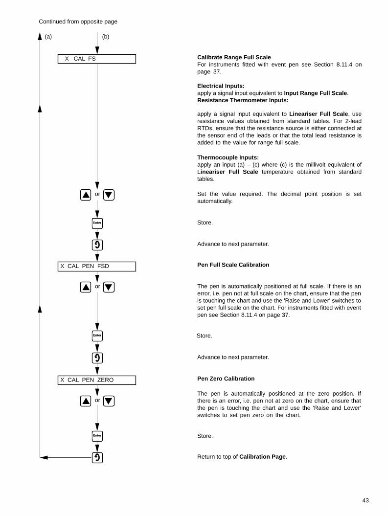
43
X CAL FS
Enter
Calibrate Range Full ScaleFor instruments fitted with event pen see Section 8.11.4 onpage 37.
apply a signal input equivalent to Input Range Full Scale.Electrical Inputs:
Resistance Thermometer Inputs:
apply a signal input equivalent to Lineariser Full Scale, useresistance values obtained from standard tables. For 2-leadRTDs, ensure that the resistance source is either connected atthe sensor end of the leads or that the total lead resistance isadded to the value for range full scale.
Thermocouple Inputs:apply an input (a) – (c) where (c) is the millivolt equivalent ofLineariser Full Scale temperature obtained from standardtables.
or Set the value required. The decimal point position is setautomatically.
Advance to next parameter.
Store.
Continued from opposite page
(a) (b)
Return to top of Calibration Page.
X CAL PEN FSD
Enter
Pen Full Scale Calibration
Store.
Advance to next parameter.
X CAL PEN ZERO
Enter
Pen Zero Calibration
Store.
or
or
The pen is automatically positioned at full scale. If there is anerror, i.e. pen not at full scale on the chart, ensure that the penis touching the chart and use the 'Raise and Lower' switches toset pen full scale on the chart. For instruments fitted with eventpen see Section 8.11.4 on page 37.
The pen is automatically positioned at the zero position. Ifthere is an error, i.e. pen not at zero on the chart, ensure thatthe pen is touching the chart and use the 'Raise and Lower'switches to set pen zero on the chart.

44
Relay Energised AboveSet Point
Relay Energised BelowSet Point
Alarm Setpoint
Measuredvalue
Relay De-energised
Relay EnergisedRelay De-energised
Relay Energised
Higher Alarm Setpoint *
Lower Alarm Setpoint *
Relay Energised
Relay De-energised
Relay Energised
Relay De-energised
Measuredvalue
Latch Energised AboveSet Point
Latch Energised BelowSet Point
Higher Alarm Setpoint
Lower Alarm Setpoint
Relay Energised
Relay De-energised
Relay Energised
Relay De-energised
Measuredvalue
Three-state OffBetween Set Points
Three-state OnBetween Set Points
11 APPENDICES11.1 Alarm Actions
Fig.12.1 On/Off
Fig. 12.2 Latch
Fig. 12.3 Three-State

PRODUCTS & CUSTOMER SUPPORT
ProductsAutomation Systems
• for the following industries:– Chemical & Pharmaceutical– Food & Beverage– Manufacturing– Metals and Minerals– Oil, Gas & Petrochemical– Pulp and Paper
Drives and Motors• AC and DC Drives, AC and DC Machines, AC Motors to 1kV• Drive Systems• Force Measurement• Servo Drives
Controllers & Recorders• Single and Multi-loop Controllers• Circular Chart , Strip Chart and Paperless Recorders• Paperless Recorders• Process Indicators
Flexible Automation• Industrial Robots and Robot Systems
Flow Measurement• Electromagnetic Flowmeters• Mass Flow Meters• Turbine Flowmeters• Flow Elements
Marine Systems & Turbochargers• Electrical Systems• Marine Equipment• Offshore Retrofit and Refurbishment
Process Analytics• Process Gas Analysis• Systems Integration
Transmitters• Pressure• Temperature• Level• Interface Modules
Valves, Actuators and Positioners• Control Valves• Actuators• Positioners
Water, Gas & Industrial Analytics Instrumentation• pH, conductivity, and dissolved oxygen transmitters and
sensors• ammonia, nitrate, phosphate, silica, sodium, chloride,
fluoride, dissolved oxygen and hydrazine analyzers.• Zirconia oxygen analyzers, katharometers, hydrogen purity
and purge-gas monitors, thermal conductivity.
Customer Support
We provide a comprehensive after sales service via a WorldwideService Organization. Contact one of the following offices fordetails on your nearest Service and Repair Centre.
United KingdomABB LimitedTel: +44 (0)1480 475321Fax: +44 (0)1480 217948
United States of AmericaABB Inc.Tel: +1 215 674 6000Fax: +1 215 674 7183
Client Warranty
Prior to installation, the equipment referred to in this manual mustbe stored in a clean, dry environment, in accordance with theCompany's published specification.
Periodic checks must be made on the equipment's condition. Inthe event of a failure under warranty, the following documentationmust be provided as substantiation:
1. A listing evidencing process operation and alarm logs at time offailure.
2. Copies of all storage, installation, operating and maintenancerecords relating to the alleged faulty unit.

IM/1
492
Issu
e 15
The Company’s policy is one of continuous productimprovement and the right is reserved to modify the
information contained herein without notice.
Printed in UK (09.04)
© ABB 2004
ABB LimitedHoward Road, St. NeotsCambridgeshirePE19 8EUUKTel: +44 (0)1480 475321Fax: +44 (0)1480 217948
ABB Inc.125 E. County Line RoadWarminster, PA 18974USA
Tel: +1 215 674 6000Fax: +1 215 674 7183
ABB has Sales & Customer Supportexpertise in over 100 countries worldwide
www.abb.com