operating instructions electronic pressure sensor uk pi209x · 5 uk 4.2 pressure monitoring /...
TRANSCRIPT

Operating instructions Electronic pressure sensor
PI209x
7060
60/0
0 0
6/20
11
UK
2
Contents1 Preliminary note 3
11 Symbols used 32 Safety instructions 33 Functions and features 4
31 Applications 44 Function 4
41 Processing of the measured signals 442 Pressure monitoring / switching function 543 Pressure monitoring/ analogue function 544 Diagnostic function 7
5 Installation86 Electrical connection 107 Operating and display elements 118 Menu 12
81 Menu structure 1282 Menu explanation 13
9 Parameter setting 1491 Parameter setting general 1492 Configuring the display (optional) 1693 Setting the output signal 16
931 Setting the output function 16932 Setting the switching limits 17933 Scaling the analogue value 17
94 User settings (optional) 18941 Zero-point calibration 18942 Setting the delay time for OUT1 18943 Setting the output polarity for OUT1 18944 Setting the damping for the switching signal 18945 Setting the damping for the analogue signal 18
95 Service functions 19951 Reading the min/max values for the system pressure 19952 Reset all parameters to the factory setting 19

3
UK
1 Preliminary note1.1 Symbols used
Instruction> Reaction, result[…] Designation of buttons, switches or indications→ Cross-reference
Important note Non-compliance can result in malfunctions or interference
2 Safety instructions• Read this ducument before installing the unit Ensure that the product is suita-
ble for your application without any restrictions• Non-adherence to the operating instructions or technical data can lead to
personal injury and/or damage to property• Inallapplicationscheckcomplianceoftheproductmaterials(→chapter12
Technical data) with the media to be measured• ForunitswithcULusapprovalandthescopeofvaliditycULus→chapter6
Electrical connection
10 Operation 19101 Read the set parameter values 19102 Fault indication 19103 Cleaning of the filter cover 20
11 Scale drawing 2112 Technical data 21
121 Setting ranges 2313 Factory setting 24

4
3 Functions and featuresThe pressure sensor detects the system pressure of machines and installations
3.1 ApplicationsType of pressure: relative pressure
Order no. Measuring range Permissible overload pressure Bursting pressure
bar PSI bar PSI bar PSIPI2093 -125 -1443627 100 1 450 350 5 070PI2094 -110 -145145 50 725 150 2 175PI2095 -14 -14558 30 435 100 1 450PI2096 -012425 -183624 20 290 50 725
mbar PSI bar PSI bar PSIPI2097 -501 000 -073145 10 145 30 435PI2098 -124250 -018362 10 145 30 435PI2099 -1 0001 000 -145145 10 145 30 435
MPa = bar ÷ 10 / kPa = bar × 100
Static and dynamic overpressures exceeding the indicated overload pres-sure are to be avoided by taking appropriate measuresThe indicated bursting pressure must not be exceeded Even if the bur-sting pressure is exceeded only for a short time, the unit can be destroyed NOTE: Risk of injury!
4 Function4.1 Processing of the measured signals• The unit displays the current system pressure• It generates 2 output signals according to the parameter setting
OUT12 selection options•switching signal for pressure limit values•diagnostic signal (in case of a fault output 1 becomes inactive)
OUT2
4 selection options•analogue signal 420 mA•analogue signal 204 mA•analogue signal 010 V•analogue signal 100 V

5
UK
4.2 Pressure monitoring / switching functionOUT1 changes its switching state if it is above or below the set switching limits (SP1, rP1) The following switching functions can be selected:• Hysteresisfunction/normallyopen:[OU1]=[Hno](→fig.1).• Hysteresisfunction/normallyclosed:[OU1]=[Hnc](→fig.1).
First the set point (SP1) is set, then the reset point (rP1) at the requested distance
• Windowfunction/normallyopen:[OU1]=[Fno](→fig.2).• Windowfunction/normallyclosed:[OU1]=[Fnc](→fig.2).
The width of the window can be set by means of the distance between SP1 and rP1 SP1 = maximum value, rP1 = minimum value
1 2
P = system pressure; HY = hysteresis; FE = window
4.3 Pressure monitoring/ analogue functionThe analogue signal can be set• [OU2] defines whether the set measuring range is provided as a 420 mA
signal ([OU2] = [I]), a 204 mA signal ([OU2] = [InEG]), a 010 V signal ([OU2] = [U]) or a 100 V signal ([OU2] = [UnEG])
Scaling can also be set by means of the teaching process or by entering a value for the ASP and AEP parameters• By teaching the analogue start point (tASP) or setting the parameter ASP you
define the measured value at which the output signal is 4 mA / 0 V (20 mA / 10 V at [InEG] / [UnEG])

6
• By teaching the analogue end point (tAEP) or setting the parameter AEP you define the measured value at which the output signal is 20 mA / 10 V (4 mA / 0 V at [InEG] / [UnEG])
Minimum distance between [ASP] and [AEP] = 25 % of the final value of the mea-suring range (turn down 1:4)Current output
Factory setting Measuring range scaled
P = system pressure, MAW = initial value of the measuring range, MEW = final value of the measuring range1 : [OU2] = [I]; 2 : [OU2] = [InEG]
The output signal is between 4 and 20 mA ([OU2] = [I]) or between 20 and 4 mA ([OU2] = [InEG]) It is also indicated:• System pressure above the measuring range:
- output signal > 20 mA if [OU2] = [I] - output signal between 4 and 38 mA if [OU2] = [InEG]
• System pressure below the measuring range: - output signal between 4 and 3,8 mA if [OU2] = [I] - output signal > 20 mA if [OU2] = [InEG]

7
UK
Voltage outputFactory setting Measuring range scaled
P = system pressure, MAW = initial value of the measuring range, MEW = final value of the measuring range1 : [OU2] = [U]; 2 : [OU2] = [UnEG]
The output signal is between 0 and 10 V ([OU2] = [U]) or between 10 and 0 V ([OU2] = [UnEG]) in the set measuring rangeIt is also indicated:• System pressure above the measuring range:
- output signal > 10 V if [OU2] = [U]• System pressure below the measuring range:
- output signal > 10 V if [OU2] = [UnEG]4.4 Diagnostic functionOutput 1 is used as a diagnostic output according to DESINA specification if OU1 = dESI• If there is no fault, the output is switched and carries UB+ (if P-n = PnP) or UB-
(if P-n = nPn)• In case of malfunctions the output becomes inactive The following malfunc-
tions are detected: - undervoltage (starting with 18V); overvoltage (starting with 33V); - temperature at the process connection too high (> 150°C) / too low (< -30°C); - intrinsic temperature of the unit too high (> 100°C) / too low (< -30°C); - RAM fault
8
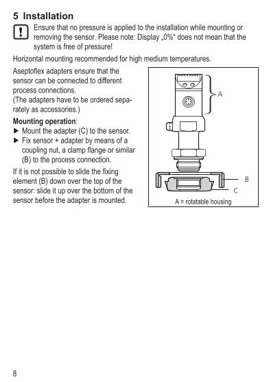
5 InstallationEnsure that no pressure is applied to the installation while mounting or removing the sensor Please note: Display „0%“ does not mean that the system is free of pressure!
Horizontal mounting recommended for high medium temperaturesAseptoflex adapters ensure that the sensor can be connected to different process connections (The adapters have to be ordered sepa-rately as accessories)Mounting operation:
Mount the adapter (C) to the sensor Fix sensor + adapter by means of a coupling nut, a clamp flange or similar (B) to the process connection
If it is not possible to slide the fixing element (B) down over the top of the sensor: slide it up over the bottom of the sensor before the adapter is mounted
A = rotatable housing
9
UK
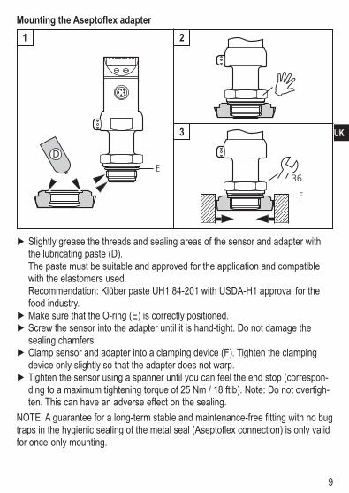
Mounting the Aseptoflex adapter
1 2
3
Slightly grease the threads and sealing areas of the sensor and adapter with the lubricating paste (D)The paste must be suitable and approved for the application and compatible with the elastomers usedRecommendation: Klüber paste UH1 84-201 with USDA-H1 approval for the food industry
Make sure that the O-ring (E) is correctly positioned Screw the sensor into the adapter until it is hand-tight Do not damage the sealing chamfers
Clamp sensor and adapter into a clamping device (F) Tighten the clamping device only slightly so that the adapter does not warp
Tighten the sensor using a spanner until you can feel the end stop (correspon-ding to a maximum tightening torque of 25 Nm / 18 ftlb) Note: Do not overtigh-ten This can have an adverse effect on the sealing
NOTE: A guarantee for a long-term stable and maintenance-free fitting with no bug traps in the hygienic sealing of the metal seal (Aseptoflex connection) is only valid for once-only mounting

10
Welding adapter First weld the adapter, then mount the sensor Follow the instructions included with the adapter
6 Electrical connectionThe unit must be connected by a qualified electricianThe national and international regulations for the installation of electrical equipment must be adhered toVoltage supply to EN50178, SELV, PELV
For units with cULus approval and the scope of validity cULus: The device shall be supplied from an isolating transformer having a secondary Listed fuse rated as noted in the following table
Overcurrent protectionControl-circuit wire size Maximum protective device rating
AmpereAWG (mm2)26 (013) 124 (020) 222 (032) 320 (052) 518 (082) 716 (13) 10
The Sensor shall be connected only by using any R/C (CYJV2) cord, having suitable ratings
Disconnect power Connect the unit as follows:
OUT1 p-switching OUT1 n-switching

11
UK
Pin 1 Ub+Pin 3 Ub-
Pin 4 (OUT1) •binary switching output for pressure monitoring•diagnostic output if [OU1] = [dESI]
Pin 2 (OUT2) •analogue output for system pressureCore colours of ifm sockets:1 = BN (brown), 2 = WH (white), 3 = BU (blue), 4 = BK (black)
7 Operating and display elements
1 to 8: Indicator LEDs - LED 1 to LED 6 = system pressure in unit of measurement as indicated on the label LEDs 5 to 6 not used for units with 3 adjustable units of measurement
- LED 7 not used - LED 8 = switching state of the output (LED lights if output 1 is switched)
9: Alphanumeric display, 4 digits - Indication of the current system pressure - Indication of the parameters and parameter values10: Set pushbutton - Setting of the parameter values (scrolling by holding pressed, incremental by pressing briefly)
11: Mode/Enter pushbutton - Selection of the parameters and acknowledgement of the parameter values

12
8 Menu8.1 Menu structure

13
UK
8.2 Menu explanation SP1/rP1 Maximum / minimum value for system pressure, at which output 1 changes
its switching statusOU1 Output function for OUT1:
•Switching signal for the limit values: hysteresis function [H ] or window function [F ], normally open [ no] or normally closed [ nc] each
•Diagnostic signal [dESI]OU2 Output function for OUT2:
•Analogue signal for the current system pressure: 420 mA [I], 204 mA [InEG], 010 V [U], 100 V [UnEG]
tCOF Teaching zero-point calibrationtASP Teaching analogue start point for the system pressure: set value at which
4 mA / 0 V are output (20 mA / 10 V on [OU2] = [InEG] / [UnEG]) tAEP Teaching analogue end point for the system pressure: set value at which
20 mA / 10 V are output (4 mA / 0 V on [OU2] = [InEG] / [UnEG]) EF Extended functions / Opening menu level 2
Uni Standard unit of measurement for the system pressure
SELdDisplay mode:•Pressure in the unit set in [Uni]•Pressure in % of the set scaling of the analogue output
ASP Analogue start point for the system pressure: measured value at which 4 mA / 0 V are output (20 mA / 10 V on [OU2] = [InEG] / [UnEG])
AEP Analogue end point for the system pressure: measured value at which 20 mA / 10 V are output (4 mA / 0 V on [OU2] = [InEG] / [UnEG])
HI Maximum value memory for the system pressureLO Minimum value memory for the system pressure
COF Zero point calibrationdS1 Switch-on delay for OUT1dr1 Reset delay for OUT1P-n Output polarity for OUT1: pnp or npn
dAP Damping for the switching output (OUT1)dAA Damping for the analogue output (OUT2)diS Update rate and orientation of the displayrES Restore the factory setting

14
9 Parameter settingDuring the parameter setting process the unit remains in the operating mode It continues its monitoring function with the existing parameters until parameter setting has been terminated
9.1 Parameter setting generalEach parameter setting requires 3 steps:
1 Selecting parameter Press [Mode/Enter] until the reque-sted parameter is displayed
2 Setting the parameter value Press [Set] and keep the buton pressed
> Current setting value of the parame-ter bit flashes for 5 s
> After 5 s: Setting value is changed: incremental by pressing briefly or scrolling by holding pressed
The numerical values are incremented continuously If the value is to be reduced: Let the display move to the maximum setting value Then the cycle starts again at the minimum setting value
3 Acknowledge parameter value Press [Mode/Enter] briefly
> The parameter is displayed again The new setting value is stored
Set more parameters Start again with step 1
Finishing parameter setting Press [Mode/Enter] several times until the current measured value is displayed or wait for 15 s
> The unit returns to the operating mode

15
UK
• Changing from menu level 1 to menu level 2: Press [Mode/Enter] until [EF] is displayed.
Press [Set] briefly > The first parameter of the submenu is
displayed (here: [Uni])If menu level 2 is protected by an access code, „Cod1“ flashes in the display
Press [Set] and keep it pressed until the valid code no is displayed
Press [Mode/Enter] brieflyDelivery by ifm electronic: no access restriction
• Locking / unlocking The unit can be locked electronically to prevent unintentional wrong settings
Ensure that the unit is in the normal operating mode
Press [Mode/Enter] + [Set] for 10 s > [Loc] is displayed
During operation: [Loc] is displayed briefly when you try to change parameter valuesFor unlocking:
Press [Mode/Enter] + [Set] for 10 s > [uLoc] is displayed
On delivery: Unlocked
• Timeout:If no button is pressed for 15 s while the parameters are being set, the unit returns to the operating mode with unchanged values
16
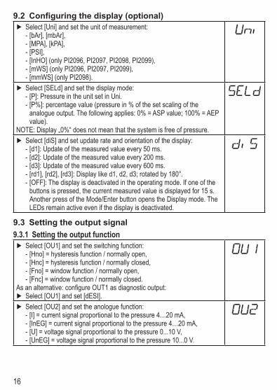
9.2 Configuring the display (optional) Select [Uni] and set the unit of measurement:
- [bAr], [mbAr], - [MPA], [kPA], - [PSI], - [InHO] (only PI2096, PI2097, PI2098, PI2099), - [mWS] (only PI2096, PI2097, PI2099), - [mmWS] (only PI2098)
Select [SELd] and set the display mode: - [P]: Pressure in the unit set in Uni - [P%]: percentage value (pressure in % of the set scaling of the analogue output The following applies: 0% = ASP value; 100% = AEP value)
NOTE: Display „0%“ does not mean that the system is free of pressure Select [diS] and set update rate and orientation of the display:
- [d1]: Update of the measured value every 50 ms - [d2]: Update of the measured value every 200 ms - [d3]: Update of the measured value every 600 ms - [rd1], [rd2], [rd3]: Display like d1, d2, d3; rotated by 180° - [OFF]: The display is deactivated in the operating mode If one of the buttons is pressed, the current measured value is displayed for 15 s Another press of the Mode/Enter button opens the Display mode The LEDs remain active even if the display is deactivated
9.3 Setting the output signal9.3.1 Setting the output function
Select [OU1] and set the switching function: - [Hno] = hysteresis function / normally open, - [Hnc] = hysteresis function / normally closed, - [Fno] = window function / normally open, - [Fnc] = window function / normally closed
As an alternative: configure OUT1 as diagnostic output: Select [OU1] and set [dESI] Select [OU2] and set the anologue function:
- [I] = current signal proportional to the pressure 4…20 mA, - [InEG] = current signal proportional to the pressure 4…20 mA, - [U] = voltage signal proportional to the pressure 010 V, - [UnEG] = voltage signal proportional to the pressure 100 V

17
UK
9.3.2 Setting the switching limits Select [SP1] and set the value at which OUT1 switches
Select [rP1] and set the value at which OUT1 switches backrP1 is always lower than SP1 The unit only accepts values which are lower than SP1
9.3.3 Scaling the analogue value Set the requested minimum pressure in the system Press [Mode/Enter] until [tASP] is displayed Press [Set] and keep the buton pressed
> The currently set value flashes Release [Set] when the display stops flashing
> The new set value is displayed Press [Mode/Enter] briefly
> The current system pressure is defined to be the start value for the analogue signal
Set the requested maximum pressure in the system Press [Mode/Enter] until [tAEP] is displayed Press [Set] and keep the buton pressed
> The currently set value flashes Release [Set] when the display stops flashing
> The new set value is displayed Press [Mode/Enter] briefly
> The current system pressure is defined to be the end value for the analogue signal
ASP/AEPcanonlybetaughtwithindefinedlimits(→12.1settingranges).Iftheteachingprocess is carried out at an invalid pressure, [UL] or [OL] is displayed After acknowledge-ment by [Mode/Enter], [Err] flashes, the ASP value / AEP value is not changedAs an alternative:
Select [ASP] and set measured value at which 4 mA / 0 V are output (20 mA / 10 V at [OU2] = [InEG] / [UnEG])
Select [AEP] and set measured value at which 20 mA / 10 V are output (4 mA / 0 V at [OU2] = [InEG] / [UnEG])
Minimum distance between ASP and AEP = 25 % of the final value of the measuring range (scaling factor 1:4)

18
9.4 User settings (optional)9.4.1 Zero-point calibration
Select [COF] and set a value between -5% and 5% of the final value of the measuring range The internal measured value “0” is shifted by this amount
As an alternative: Automatic adaptation offset (setting range 0 bar ±5%); eg in the event of a deviation of the mounting location of the sensor and the zero point level for level measurement
Make sure that no pressure is applied to the system Press [Mode/Enter] until [tCOF] is displayed Press [Set] and keep the buton pressed
> The current offset value (in %) briefly flashes, then the current system pressure (in the selected display unit) is displayed
Release [Set] Press [Mode/Enter] briefly to confirm the new offset value
9.4.2 Setting the delay time for OUT1[dS1] = switch-on delay / [dr1] = switch-off delay
Select [dS1] or [dr1] and set the value between 01 and 500 s (at 00 the delay time is not active)
9.4.3 Setting the output polarity for OUT1 Select [P-n] and set [PnP] or [nPn]
9.4.4 Setting the damping for the switching signal Select [dAP] and set value between 01 and 1000 s (at 00 = [dAP] is not active)
dAP value = response time between pressure change and change of the switching status in seconds[dAP] influences the switching frequency: fmax = 1 ÷ 2dAP [dAP] also affects the display
9.4.5 Setting the damping for the analogue signal Select [dAA] and set value between 01 and 1000 s (at 00 = [dAA] is not active)
dAA value = response time between pressure change and change of the analogue signal in seconds

19
UK
9.5 Service functions9.5.1 Reading the min./max. values for the system pressure
Select [HI] or [LO], press [Set] briefly[HI] = maximum value, [LO] = minimum value
Delete memory: Select [HI] or [LO] Press [SET] until [----] is displayed Press [MODE/ENTER] briefly
9.5.2 Reset all parameters to the factory setting Select [rES] Press [SET] until [----] is displayed Press [MODE/ENTER] briefly
It makes sense to note down your own settings before executing the func-tion(→13Factorypreset).
10 OperationAfter power on of the supply voltage the unit is in the Run mode (= normal operati-on) It carries out its measurement and evaluation functions and generates output signals according to the set parametersOperatingindicators→chapter7Operatinganddisplayelements.
10.1 Read the set parameter values Press [Mode/Enter] until the requested parameter is displayed Press [Set] briefly
> The unit displays the corresponding parameter value for about 15 s After another 15 s the unit returns to the Run mode
10.2 Fault indication[OL] Overload pressure (measuring range exceeded)[UL] Underpressure range (measuring range below the minimum value)[SC1] Short circuit in OUT1; the output is switched off as long as the short circuit exists[Err] Internal fault, invalid input
The faults SC1 and Err are indicated even if the display is deactivated
20
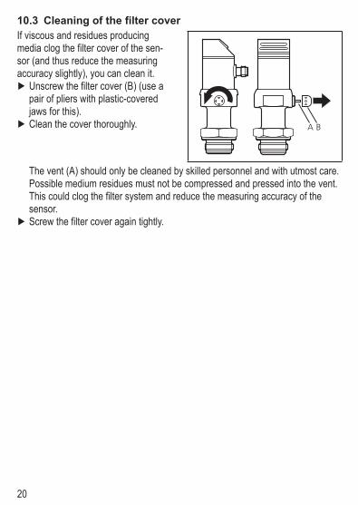
10.3 Cleaning of the filter coverIf viscous and residues producing media clog the filter cover of the sen-sor (and thus reduce the measuring accuracy slightly), you can clean it
Unscrew the filter cover (B) (use a pair of pliers with plastic-covered jaws for this)
Clean the cover thoroughly
The vent (A) should only be cleaned by skilled personnel and with utmost carePossible medium residues must not be compressed and pressed into the vent This could clog the filter system and reduce the measuring accuracy of the sensor
Screw the filter cover again tightly

21
UK
11 Scale drawing
Dimensions are in millimeters1: display2: LED’s3: programming button4: Aseptoflex sealing edge5: Aseptoflex thread
12 Technical dataOperating voltage [V] 1832 DC Current consumption [mA] < 50 Current rating [mA] 250 Short-circuit / reverse polarity / overload protection, integrated watchdogVoltage drop [V] < 2Power-on delay time [s] 05Min response time switching outputs [s] 01Switching frequency [Hz] 6Analogue output 420 mA / 204 mA / 010 V / 100 V Max.loadcurrentoutput[Ω] (Ub - 10) x 50 Min.loadwithvoltageoutput[Ω] 2000 Step response time analogue output [ms] 25

22
Accuracy / deviation (in % of the span)1)
- Characteristics deviation (linearity incl hysteresis and repeatability)2) < ± 02- Linearity < ± 015- Hysteresis < ± 015- Repeatability (with temperature fluctuations < 10 K) < ± 01- Long-term stability (in % of the span per year)< ± 01- Temperature coefficient (TC) in the compensated temperature range 0 70°C (in % of the span per 10 K) - Greatest TC of the zero point < ± 005 - Greatest TC of the span < ± 015Materials (wetted parts) stainless steel 316L / 14435, surface characteristics: Ra < 04 / Rz 4 ceramics (999 % Al2O3); PTFE Housing materials stainless steel 316L / 14404; PC (Makrolon); PBT (Pocan); PEI; FPM (Viton); PTFEProtection IP 67 / IP 69KProtection class IIIInsulationresistance[MΩ] > 100 (500 V DC)Shock resistance [g] 50 (DIN / IEC 68-2-27, 11ms)Vibration resistance [g] 20 (DIN / IEC 68-2-6, 10 - 2000 Hz)Switching cycles min 100 millionOperating temperature [°C] -25 +80Medium temperature [°C] -25125 (145 max 1h)Storage temperature [°C] -40+100EMC EN 61000-4-2 ESD: 4 / 8 KV EN 61000-4-3 HF radiated: 10 V/m EN 61000-4-4 Burst: 2 KV EN 61000-4-5 Surge: 05 / 1 KV EN 61000-4-6 HF conducted: 10 V
1) all indications are referred to a turn down of 1:12) limit value setting to DIN 16086

23
UK
12.1 Setting rangesSP1 rP1 ASP AEP
ΔPmin max min max min max min max
PI20
93 bar -096 2500 -100 2496 -100 1874 524 2500 002PSI -138 3627 -144 3621 -144 2718 762 3627 03MPa -0096 2500 -0100 2496 -0100 1874 0524 2500 0002
PI20
94 bar -098 1000 -100 998 -100 750 150 1000 001PSI -142 1450 -145 1447 -145 1087 218 1450 01MPa 0098 1000 -0100 0998 -0100 0750 0150 1000 0001
PI20
95 bar -0990 4000 -1000 3990 -1000 3000 0000 4000 0005PSI -1435 5800 -1450 5785 -1450 4350 000 5800 005kPa -990 4000 -1000 3990 -1000 3000 00 4000 05
PI20
96
bar -0120 2500 -0124 2496 -0124 1880 0500 2500 0002PSI -174 3627 -180 3621 -180 2727 726 3627 003kPa -120 2500 -124 2496 -124 1880 500 2500 02
inH2O -48 1004 -50 1002 -50 755 201 1004 1mWS -122 2549 -126 2545 -126 1917 510 2549 001
PI20
97
mbar -48 1000 -50 998 -50 750 200 1000 1PSI -070 1450 -073 1447 -073 1088 290 1450 001kPa -48 1000 -50 998 -50 750 200 1000 01
inH2O -192 4016 -200 4008 -200 3012 804 4016 04mWS -049 1020 -051 1018 -051 765 204 1020 001
PI20
98
mbar -120 2500 -124 2496 -124 1874 500 2500 02kPa -120 2500 -124 2496 -124 1874 500 250 002
inH2O -48 1004 -50 1002 -50 753 201 1004 01mmWS -122 2250 -126 2546 -126 1912 510 2250 2
PI20
99
mbar -998 1000 -1000 998 -1000 500 -500 1000 1PSI -1445 1450 -1450 1445 -1450 725 -725 1450 005kPa -998 1000 -1000 998 -1000 500 -500 1000 01
inH2O -400 401 -401 400 -401 201 -201 401 1mWS -1018 1020 -1020 1018 -1020 510 -510 1020 001
ΔP=increments

24
13 Factory settingFactory setting User setting
OU1 HnoOU2 ISP1 25% VMR*rP1 23% VMR*ASP / tASP 0% VMR*AEP / tAEP 100% VMR*COF / tCOF 0.0dS1 0.0dr1 0.0P-n pnpdAP 0.1dAA 0.1Uni bAr / mbArSELd Pdis d2* = the indicated percentage of the final value of the measuring range (VMR) of the corresponding sensor in bar / mbar is set
More information at wwwifmcom