operating instructions -...
TRANSCRIPT
Operating Instructions
Century 3 Vacuum Autoclave
16 & 22 Litre Model Options

- 2 -
English
Contents.
Page 3 - Decals, displays and controls.
Page 4 - Introduction / Types of load & loading.
Page 5 - Operating Symbols, Controls and Displays.
Page 6 - Operation.
Page 7 - Operation continued.
Page 8 - Additional Operations.
Page 9 - Essential Information.
Page 10 - Routine Care & Maintenance.
Page 11 - Troubleshooting.
Page 12 - Recovery sequences.
Page 13 - Additional Information.
Page 14 - Specifications.
Page 15 - Type B Cycle profile.
Page 16 - Rapid Vacuum Cycle profile.
Page 17 - Non Vacuum cycle profile.
- 3 -

- 4 -
Thank you for choosing the Prestige Medical Century 3 Autoclave.
All “Type B” vacuum cycles on this autoclave use the triple pulse fractionated vacuum system and are fitted with an active air leakdetection system.
Non-vacuum cycles use the thermodynamic air displacement system.
Drying cycles employ a “closed door” system.
An “Auto-cycle start” option is included which allows the user to programme the time of day at which the selected cycle should start.
Before unpacking, refer to the “Manual Handling” section on page 13.
Whilst unpacking check the unit for transit damage. If damage is found, please report this to the shipping agent immediately, inwriting and then notify your dealer.
Product contents will contain the following: -• Autoclave with internal furniture.• Handbook and warranty card.• Performance Test Certificate and Certificate of Conformance for pressure vessel (all UK models).• Bowie Dick Test Pack or Test Helix.• Waste water container.
This autoclave has been qualified to sterilize loads as defined by prEN13060.
Cycles C1i & C1ii – Wrapped, pouched, solid, hollow instruments (length to diameter ratio 750:1 Length may be doubled for tubesthat are open at both ends) and porous items.
Cycle C2i – Unwrapped, un-pouched, solid or hollow instruments (length to diameter ratio 110:1 Length may be doubled for tubesthat are open at both ends).
Cycles C2ii – Process Challenge Device cycle (Bowie Dick Test Pack or Helix). To be used for validation of cycles C1i and C1ii.
Cycles C3 & C4 – Unwrapped solid instruments only.
• A “responsible person” must qualify other loads as suitable. Refer to “Additional Information”.• Maximum load per instrument tray is 2 kg. Refer to “Technical Specifications” for the maximum instrument load for the
autoclave.• All instruments must be cleaned prior to sterilizing.• Wrapped or pouched loads should not touch adjacent loads when placed in the rack. Pouches must be used for only one item.• When placing on a tray, ensure items are placed on the ribs of the tray (to aid drainage), they do not touch each other and the
load does not touch the other trays or chamber in any way.• Always use the lifting device when removing trays from the autoclave, as they may be hot. Long trays should be supported at
their rear as they become free of the tray carrier. Do not use an unprotected hand to hold hot trays.
English
Introduction.
Types of load and loading.
WARNING!Refer to the instrument manufacturer about their suitability for autoclaving and the maximum temperature that theinstruments can withstand.
- 5 -
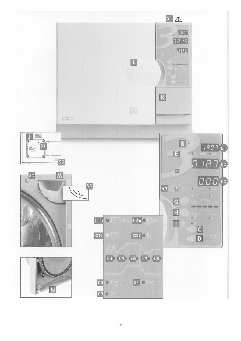
The following descriptions refer to the symbols, controls and displays shown on Page 3 of this manual.
Symbols:S1 IMPORTANT: Read Operating Instructions before use.S2 Do not use tap water.S3 Maximum water fill line.S4 Fill water tank.S5 Hot parts (behind) Do Not Touch. Also behind door (L).
General Controls / Operations:Note: The function is selected when the LED adjacent to the button is illuminated.
A Not applicable. B Standby / Ready button.C Cycle start button. D Door open button.E Select time/date/cycle counter. F Adjust time/date settings (F1/F2)G Select vacuum cycles. H Select Non-vacuum cycles.I Select “Additional drying”. J Fuses (located behind access panel).K Printer door. L Main door.M Water fill. N Fresh water tank drain.
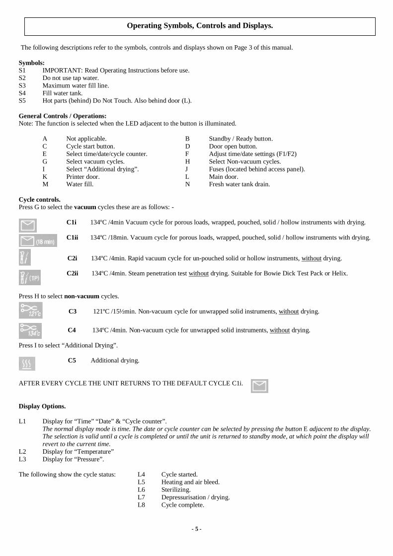
Cycle controls.Press G to select the vacuum cycles these are as follows: -
C1i 134ºC /4min Vacuum cycle for porous loads, wrapped, pouched, solid / hollow instruments with drying.
C1ii 134ºC /18min. Vacuum cycle for porous loads, wrapped, pouched, solid / hollow instruments with drying.
C2i 134ºC /4min. Rapid vacuum cycle for un-pouched solid or hollow instruments, without drying.
C2ii 134ºC /4min. Steam penetration test without drying. Suitable for Bowie Dick Test Pack or Helix.
Press H to select non-vacuum cycles.
C3 121ºC /15½min. Non-vacuum cycle for unwrapped solid instruments, without drying.
C4 134ºC /4min. Non-vacuum cycle for unwrapped solid instruments, without drying.
Press I to select “Additional Drying”.
C5 Additional drying.
AFTER EVERY CYCLE THE UNIT RETURNS TO THE DEFAULT CYCLE C1i.
Display Options.
L1 Display for “Time” “Date” & “Cycle counter”.The normal display mode is time. The date or cycle counter can be selected by pressing the button E adjacent to the display.The selection is valid until a cycle is completed or until the unit is returned to standby mode, at which point the display willrevert to the current time.
L2 Display for “Temperature”L3 Display for “Pressure”.
The following show the cycle status: L4 Cycle started.L5 Heating and air bleed.L6 Sterilizing.L7 Depressurisation / drying.L8 Cycle complete.
Operating Symbols, Controls and Displays.
- 6 -
Please take time to read these instructions before using the autoclave. It is essential that the operator is correctly trainedand a “Responsible Person” has been assigned for the management of the autoclave.By following these simple step-by-step instructions you can ensure your instruments are correctly sterilized every time.
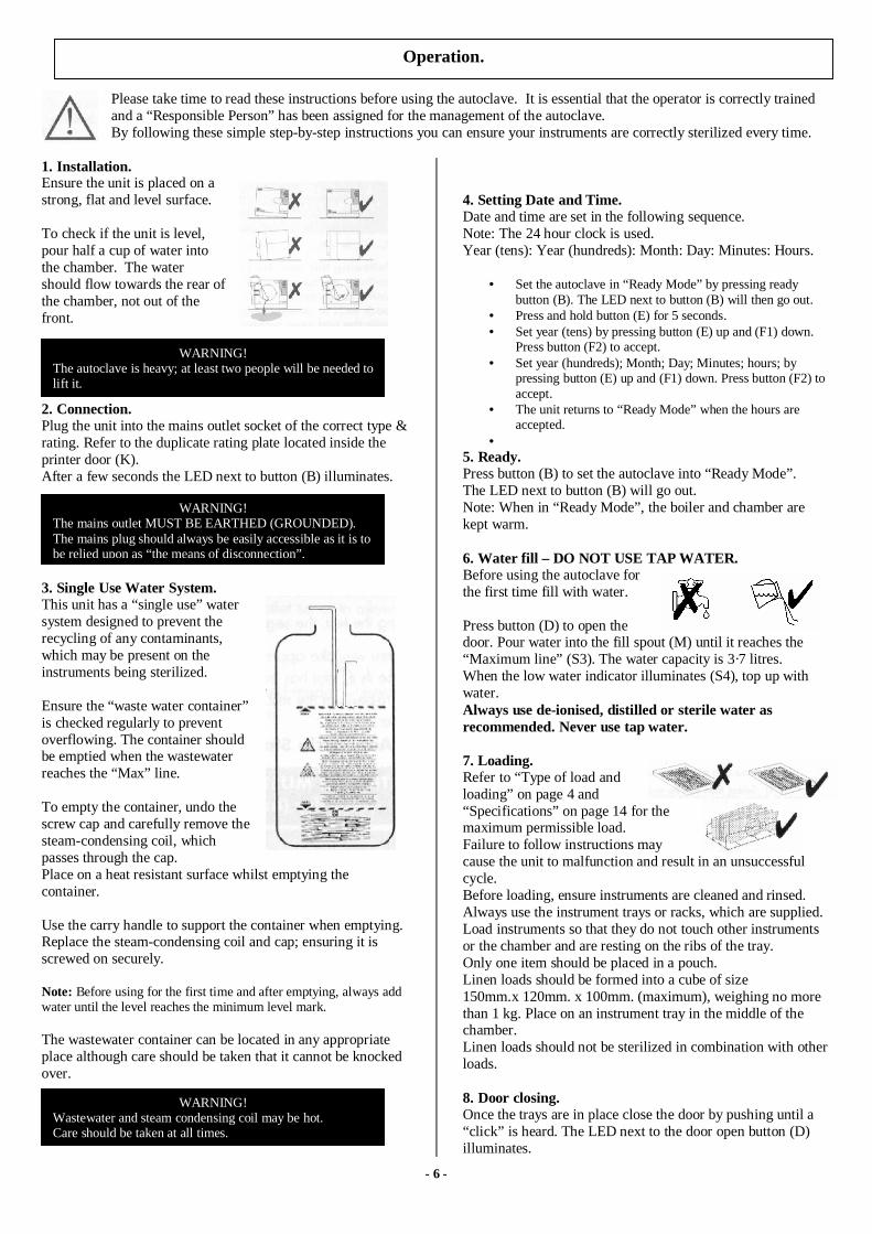
1. Installation.Ensure the unit is placed on astrong, flat and level surface.
To check if the unit is level,pour half a cup of water intothe chamber. The watershould flow towards the rear ofthe chamber, not out of thefront.
2. Connection.Plug the unit into the mains outlet socket of the correct type &rating. Refer to the duplicate rating plate located inside theprinter door (K).After a few seconds the LED next to button (B) illuminates.
3. Single Use Water System.This unit has a “single use” watersystem designed to prevent therecycling of any contaminants,which may be present on theinstruments being sterilized.
Ensure the “waste water container”is checked regularly to preventoverflowing. The container shouldbe emptied when the wastewaterreaches the “Max” line.
To empty the container, undo thescrew cap and carefully remove thesteam-condensing coil, whichpasses through the cap.Place on a heat resistant surface whilst emptying thecontainer.
Use the carry handle to support the container when emptying.Replace the steam-condensing coil and cap; ensuring it isscrewed on securely.
Note: Before using for the first time and after emptying, always addwater until the level reaches the minimum level mark.
The wastewater container can be located in any appropriateplace although care should be taken that it cannot be knockedover.
4. Setting Date and Time.Date and time are set in the following sequence.Note: The 24 hour clock is used.Year (tens): Year (hundreds): Month: Day: Minutes: Hours.
• Set the autoclave in “Ready Mode” by pressing readybutton (B). The LED next to button (B) will then go out.
• Press and hold button (E) for 5 seconds.• Set year (tens) by pressing button (E) up and (F1) down.
Press button (F2) to accept.• Set year (hundreds); Month; Day; Minutes; hours; by
pressing button (E) up and (F1) down. Press button (F2) toaccept.
• The unit returns to “Ready Mode” when the hours areaccepted.
•5. Ready.Press button (B) to set the autoclave into “Ready Mode”.The LED next to button (B) will go out.Note: When in “Ready Mode”, the boiler and chamber arekept warm.
6. Water fill – DO NOT USE TAP WATER.Before using the autoclave forthe first time fill with water.
Press button (D) to open thedoor. Pour water into the fill spout (M) until it reaches the“Maximum line” (S3). The water capacity is 3·7 litres.When the low water indicator illuminates (S4), top up withwater.Always use de-ionised, distilled or sterile water asrecommended. Never use tap water.
7. Loading.Refer to “Type of load andloading” on page 4 and“Specifications” on page 14 for themaximum permissible load.Failure to follow instructions maycause the unit to malfunction and result in an unsuccessfulcycle.Before loading, ensure instruments are cleaned and rinsed.Always use the instrument trays or racks, which are supplied.Load instruments so that they do not touch other instrumentsor the chamber and are resting on the ribs of the tray.Only one item should be placed in a pouch.Linen loads should be formed into a cube of size150mm.x 120mm. x 100mm. (maximum), weighing no morethan 1 kg. Place on an instrument tray in the middle of thechamber.Linen loads should not be sterilized in combination with otherloads.
8. Door closing.Once the trays are in place close the door by pushing until a“click” is heard. The LED next to the door open button (D)illuminates.
Operation.
WARNING!The autoclave is heavy; at least two people will be needed tolift it.
WARNING!The mains outlet MUST BE EARTHED (GROUNDED).The mains plug should always be easily accessible as it is tobe relied upon as “the means of disconnection”.
WARNING!Wastewater and steam condensing coil may be hot.Care should be taken at all times.

- 7 -
9. Cycle Options.After each cycle the unit returns to the default cycle “C1i”134ºC /4min Vacuum cycle for porous loads, wrapped,pouched, solid / hollow instruments with drying.
Cycle options are:
Press G to select the vacuum cycles these are: -
134ºC /4min Vacuum cycle for porous loads,wrapped, pouched, solid / hollow instruments with
drying.
134ºC /18min.Vacuum cycle for porous loads, wrapped, pouched, solid / hollow instruments with
drying.
134ºC /4min. Rapid vacuum cycle for un-pouchedsolid or hollow instruments, without drying.
134ºC /4min. Steam penetration test without drying. Suitable for Bowie Dick Test Pack or Helix.
Press H to select non-vacuum cycles.
121ºC /15½min. Non-vacuum cycle for unwrapped solid instruments, without drying.
134ºC /4min.Non-vacuum cycle for unwrapped solid instruments, without drying.
Press I to select “Additional Drying”.
Additional drying. This option can be added before orafter a cycle.
NB. Although additional drying can be selected for the SteamPenetration Test this does not in fact activate drying on thiscycle. The only way to get drying on this cycle is to adddrying after the cycle has completed.
To select before starting a cycle:(i) Press button (I) once. L4 illuminates to indicate
10 additional minutes.(ii) Press (I) a second time. L4 & L5 illuminate to
indicate 20 additional minutes.(iii) Press (I) a third time. L4 L5 & L6 illuminate to
indicate 30 additional minutes.(iv) Press (I) a fourth time. This cancels additional
drying.(v) Select, then start the required cycle. See “10”.
To select after a cycle has been completed:(i) With the door closed press and hold button (I)
for 10seconds. L7 flashes to indicate 10minutedrying in progress.
(ii) Press button (I) once. L4 illuminates to indicate10 additional minutes. Now press and holdbutton (I) for 10seconds. L4 and L5 areilluminated. Then L7 flashes to indicate20minute drying in progress.
(iii) Press button (I) twice. L4 & L5 illuminated toindicate 20 additional minutes. Now press andhold button (I) for 10seconds. L4 L5 and L6 areilluminated. L7 now flashes to indicate 30minutedrying in progress.
10. Start Cycle.Press button (C) to start a fully automatic cycle. A visualdisplay shows the stages of the cycle:
Stage 1 Cycle started (L4)Stage 2 Heating and air bleed (L5)Stage 3 Sterilizing (L6)Stage 4 Depressurisation / drying (L7)Stage 5 Cycle completed (L8)
11. Opening door.At the end of a cycle a buzzer sounds 3 times. Press button(D) to open the door, allowing access to the load.
Operation (continued).
- 8 -
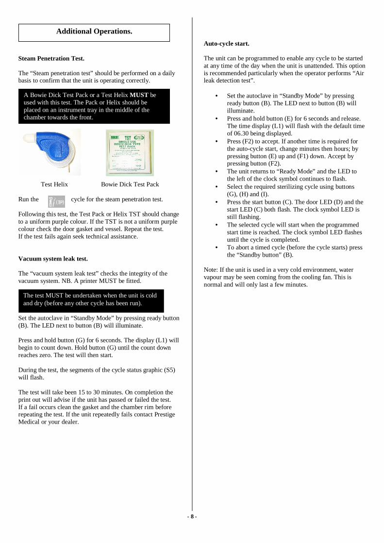
Steam Penetration Test.
The “Steam penetration test” should be performed on a dailybasis to confirm that the unit is operating correctly.
Test Helix Bowie Dick Test Pack
Run the cycle for the steam penetration test.
Following this test, the Test Pack or Helix TST should changeto a uniform purple colour. If the TST is not a uniform purplecolour check the door gasket and vessel. Repeat the test.If the test fails again seek technical assistance.
Vacuum system leak test.
The “vacuum system leak test” checks the integrity of thevacuum system. NB. A printer MUST be fitted.
Set the autoclave in “Standby Mode” by pressing ready button(B). The LED next to button (B) will illuminate.
Press and hold button (G) for 6 seconds. The display (L1) willbegin to count down. Hold button (G) until the count downreaches zero. The test will then start.
During the test, the segments of the cycle status graphic (S5)will flash.
The test will take been 15 to 30 minutes. On completion theprint out will advise if the unit has passed or failed the test.If a fail occurs clean the gasket and the chamber rim beforerepeating the test. If the unit repeatedly fails contact PrestigeMedical or your dealer.
Auto-cycle start.
The unit can be programmed to enable any cycle to be startedat any time of the day when the unit is unattended. This optionis recommended particularly when the operator performs “Airleak detection test”.
• Set the autoclave in “Standby Mode” by pressingready button (B). The LED next to button (B) willilluminate.
• Press and hold button (E) for 6 seconds and release.The time display (L1) will flash with the default timeof 06.30 being displayed.
• Press (F2) to accept. If another time is required forthe auto-cycle start, change minutes then hours; bypressing button (E) up and (F1) down. Accept bypressing button (F2).
• The unit returns to “Ready Mode” and the LED tothe left of the clock symbol continues to flash.
• Select the required sterilizing cycle using buttons(G), (H) and (I).
• Press the start button (C). The door LED (D) and thestart LED (C) both flash. The clock symbol LED isstill flashing.
• The selected cycle will start when the programmedstart time is reached. The clock symbol LED flashesuntil the cycle is completed.
• To abort a timed cycle (before the cycle starts) pressthe “Standby button” (B).
Note: If the unit is used in a very cold environment, watervapour may be seen coming from the cooling fan. This isnormal and will only last a few minutes.
Additional Operations.
A Bowie Dick Test Pack or a Test Helix MUST beused with this test. The Pack or Helix should beplaced on an instrument tray in the middle of thechamber towards the front.
The test MUST be undertaken when the unit is coldand dry (before any other cycle has been run).

- 9 -
To ensure the autoclave continues to operate correctly it isimportant to follow the following points and to carry out thenecessary care and maintenance procedures as specified.
Do ensure that..……you read and follow these operating instructions.
…the load is suitable for sterilizing and the cycle selected.
…the load can be sterilized at the selected temperature.
…the load has been cleaned.
…the load has been rinsed thoroughly in clean water prior to sterilization to avoid any chemical residues left after cleaning contaminating the autoclave.
This product is not a washing / cleaning machine.
…when placing instruments on trays, ensure that they are placed on the ribs of the tray (to help drainage), they must not touch each other and must not interfere with other trays or the chamber above.
…only distilled, de-ionised or sterile water is used (as recommended).
…the autoclave is in a draught free area.
…the autoclave cooling fan outlet is at least 100mm. from any nearby surface. If the nearby surface is cold, then condensation may occur.
…the autoclave is not installed in an enclosed cupboard space.
…all other exterior product panels are 50mm. clear of adjoining surfaces to allow air circulation.
…the door is left ajar when not in use.
…you quote model/serial number (which are located inside the printer door) and date of purchase in all correspondence.…only qualified personnel service the autoclave.
Do not….
…lose this handbook.
…add any chemicals whatsoever to the water.
…attempt to sterilize volatile substances, toxic materials or other unsuitable loads. Refer to your “Responsible Person” for advice.
…place the autoclave in direct sunlight.
…place the autoclave on heat sensitive surfaces.
…use inappropriate cleaning materials.
…drop or abuse the autoclave.
…use in areas of risk associated with flammable materials or gases.
…remove the casing or attempt to service or repair the autoclave.
Essential Information.
It is recommended that a Chemical Indicator strip beused every cycle to verify that the sterilizing cycle iseffective. If the Chemical Indicator strip fails to changecolour repeat the cycle. If it still fails to change colourthen arrange for a service.

- 10 -
Daily Maintenance
Gasket
THE GASKET MUST BE CLEANED ON A DAILY BASIS,BEFORE USING THE AUTOCLAVE.
Wipe exposed surface of the gasket andthe surface of the vessel with warmsoapy water using a lint free dampcloth.
Wipe both the gasket and the vessel again with water using alint free damp cloth to remove any residual soap.
Gasket Replacement.
Should the gasket develop a persistent leak it should beremoved, cleaned thoroughly in warm soapy water and shakendry. Do not wipe with a cloth. The door gasket plate must alsobe cleaned.
If the leak persists you should obtain and fit a new gasket.
To remove the gasket, undo the two dome nuts in the centre ofthe gasket plate. Remove the plate/gasket assembly and thenremove the gasket from the plate.
During re-assembly, place new sealing washers under theheads of the dome nuts.
Ensure that the entry port plug aligns with the hole in the castlid.
DO NOT over-tighten the dome nuts as this may damage thethread.
Every 250 cycles.
Clean the autoclave using Autoclave cleaning kit(Part No. 289138A).
Every 500 cycles.
Change the air filter situated at the front of the autoclave.
Gently pull out the filter, detach fromthe tubing and fit the replacement.
Push the filter and tube back into thehole.
Exterior surfaces (as required).
Exterior surfaces should be cleaned with warm soapy waterusing a damp cloth.
For persistent marks, use a gentle cream cleaner.
Fresh water tank / Wastewater container.
On a monthly basis, fully drain the water tank and leaveovernight (use Autoclave cleaning kit Part No. 289138).Drain, then refill with fresh water. Repeat this operation twicemore to remove any residue.Always use de-ionised, distilled or sterile water asrecommended. NEVER USE TAP WATER.
Routine Maintenance.
Every three months check the calibration – refer to the servicemanual.
Annually replace the water filters.
Routine Care & Maintenance.
WARNING!Disconnect the autoclave from the mains power supplybefore cleaning.
WARNING!Failure to perform these procedures may result in the unitshowing UOD1 on the display (UOD1 indicates that theunit may have been contaminated and could fail to operatecorrectly).
- 11 -
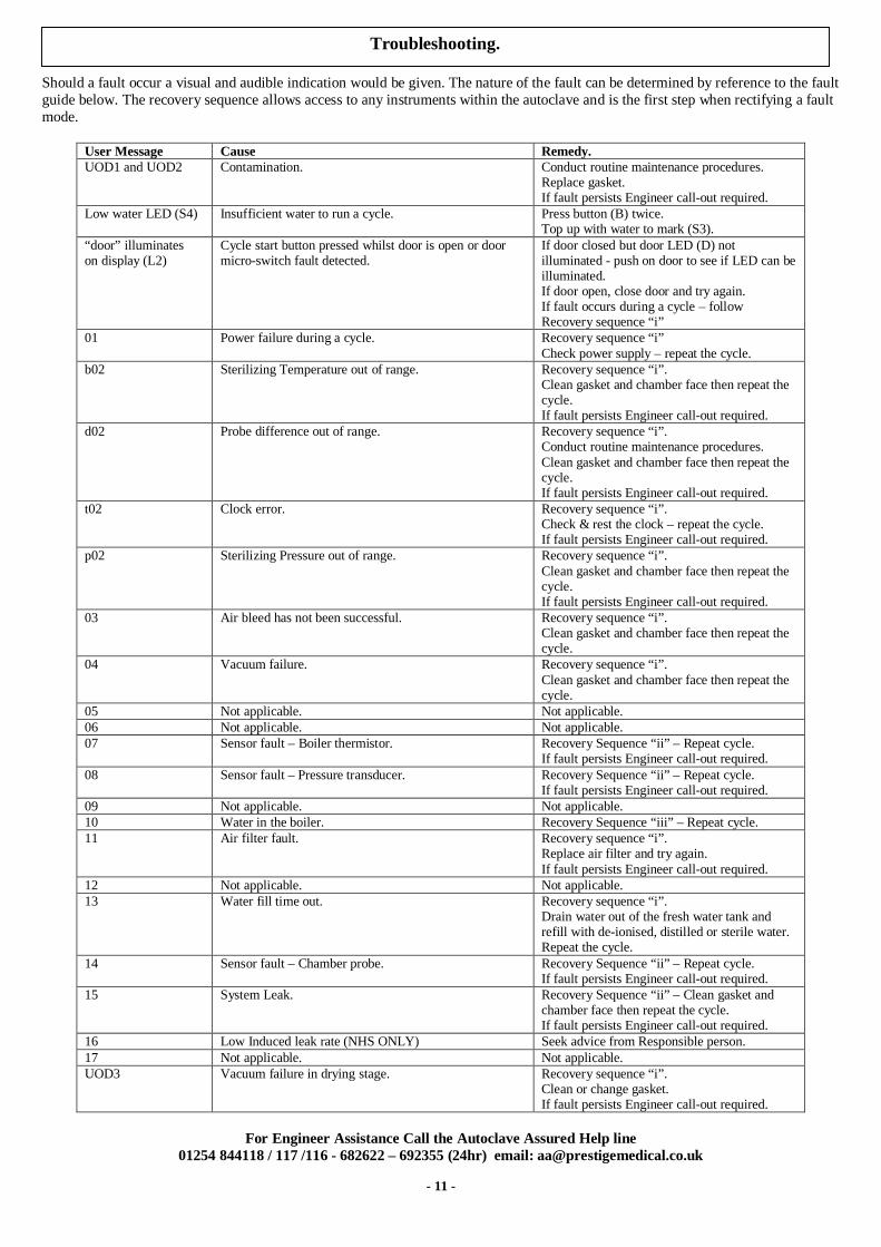
Should a fault occur a visual and audible indication would be given. The nature of the fault can be determined by reference to the faultguide below. The recovery sequence allows access to any instruments within the autoclave and is the first step when rectifying a faultmode.
User Message Cause Remedy.UOD1 and UOD2 Contamination. Conduct routine maintenance procedures.
Replace gasket.If fault persists Engineer call-out required.
Low water LED (S4) Insufficient water to run a cycle. Press button (B) twice.Top up with water to mark (S3).
“door” illuminateson display (L2)
Cycle start button pressed whilst door is open or doormicro-switch fault detected.
If door closed but door LED (D) notilluminated - push on door to see if LED can beilluminated.If door open, close door and try again.If fault occurs during a cycle – followRecovery sequence “i”
01 Power failure during a cycle. Recovery sequence “i”Check power supply – repeat the cycle.
b02 Sterilizing Temperature out of range. Recovery sequence “i”.Clean gasket and chamber face then repeat thecycle.If fault persists Engineer call-out required.
d02 Probe difference out of range. Recovery sequence “i”.Conduct routine maintenance procedures.Clean gasket and chamber face then repeat thecycle.If fault persists Engineer call-out required.
t02 Clock error. Recovery sequence “i”.Check & rest the clock – repeat the cycle.If fault persists Engineer call-out required.
p02 Sterilizing Pressure out of range. Recovery sequence “i”.Clean gasket and chamber face then repeat thecycle.If fault persists Engineer call-out required.
03 Air bleed has not been successful. Recovery sequence “i”.Clean gasket and chamber face then repeat thecycle.
04 Vacuum failure. Recovery sequence “i”.Clean gasket and chamber face then repeat thecycle.
05 Not applicable. Not applicable.06 Not applicable. Not applicable.07 Sensor fault – Boiler thermistor. Recovery Sequence “ii” – Repeat cycle.
If fault persists Engineer call-out required.08 Sensor fault – Pressure transducer. Recovery Sequence “ii” – Repeat cycle.
If fault persists Engineer call-out required.09 Not applicable. Not applicable.10 Water in the boiler. Recovery Sequence “iii” – Repeat cycle.11 Air filter fault. Recovery sequence “i”.
Replace air filter and try again.If fault persists Engineer call-out required.
12 Not applicable. Not applicable.13 Water fill time out. Recovery sequence “i”.
Drain water out of the fresh water tank andrefill with de-ionised, distilled or sterile water.Repeat the cycle.
14 Sensor fault – Chamber probe. Recovery Sequence “ii” – Repeat cycle.If fault persists Engineer call-out required.
15 System Leak. Recovery Sequence “ii” – Clean gasket andchamber face then repeat the cycle.If fault persists Engineer call-out required.
16 Low Induced leak rate (NHS ONLY) Seek advice from Responsible person.17 Not applicable. Not applicable.UOD3 Vacuum failure in drying stage. Recovery sequence “i”.
Clean or change gasket.If fault persists Engineer call-out required.
For Engineer Assistance Call the Autoclave Assured Help line01254 844118 / 117 /116 - 682622 – 692355 (24hr) email: [email protected]
Troubleshooting.

- 12 -
Recovery sequence (allows instruments to be removed from the unit).Recovery Sequence “i”Press button (B)Stabilize (no flashing or bleeping)
Press button (B)“Recover”
Recovery Sequence “ii”Press button (B)Stabilize (no flashing or bleeping)
NB: Cannot proceed. Switch off at mainssupply. Service required.
Recovery Sequence “iii”Press button (B)Stabilize (no flashing or bleeping)
Press button (B) to enter “Ready Mode”
The Recovery Sequence (depending on where the fault occurs) will flush the water from the boiler and eventually complete the cyclewith a continuous bleeping to indicate recovery is completed.
Important.
Before restarting a cycle, check that the mains plug is fully inserted into the mains outlet socket and the outlet is of theearthed/grounded type.
Should all power be lost the door cannot be opened until power is restored.
Should an internal power failure occur, the door cannot be opened until a service has been carried out.
Should it be clear that an indicating device is suspect, a service will be required to correct the condition.
Should a safety feature operate, unplug the unit and call for a service – do not attempt to correct the fault.
Primary safety features:
Two primary features have been fitted – a pressure release valve and a boiler over temperature safety cut out.

- 13 -
Operator: The person assigned to use the autoclave.
Responsible Person:The person who is responsible for the management of theequipment, load assignment, care and maintenance. Thisperson is also responsible for ensuring that all applicableHealth & Safety Regulations are applied including thoserelating to the pressure vessel.This person must verify that only suitably qualified personsundertake repair and maintenance work other than thatdescribed under “Routine Care and Maintenance” within thishandbook.
Qualified Person:A person who is qualified by training or experience to arecognised level in respect of the work to be undertaken.
Service: Calibration and maintenance as required.
Manual Handling:Due to the weight of the unit two people are required whenunpacking or moving the product.
UNPACKING.When lifting the unit out of the box ensure there is one personon either side of the unit. Lift out of the box and place on thework surface.POSITIONING.Start lifting by holding the unit below the printer door. Asclearance is gained, lift at the other corners. Place in position,and release in the reverse order to lifting. NOTE Always drainthe water tank before moving. Before moving always allow 30minutes after use for the unit to cool down.
Cleaning Materials:o Mild washing up liquid.o Non-abrasive cream cleaner.o Disinfectant diluted in water.o Autoclave Cleaning Kit 289138.
Product decontamination.Should the unit require repair, it must be decontaminated inaccordance with a recognised procedure prior to return or on-site repair. A statement of equipment contamination statusmust be available with the product. Details of a suitableprocedure are available on request.
Approvals:Approvals are all model specific. However, the followingstandards apply in whole or part:
o Medical Devices Directive (MDD 93/42/EEC)o Electro Magnetic Compatibility Directive.o European Sterilizer Standard (prEN13060)o Pressure vessel to ASME Section 8 Div 1.o BS EN 61010 Parts 1 / 2o UL/CSA 3101
Spares:Only those spare parts supplied or specified by PrestigeMedical should be used in the maintenance of the autoclave.Use of unauthorised parts will invalidate any warranty andmay adversely affect the performance or safety of the unit.
Accessories:
Printer (Part No.289083):Optional and can be fitted by the user.
Printer roll (Part No.279001):Replacement roll for optional printer.
Instrument Trays:282mm. Tray (Part No.279006).430mm. Tray (Part No.279005).
Pouch Rack (Part No.279238):Three-tray capacity.
Tray / Rack lifter (Part No.279007):For the removal of trays or racks.
Sealing gasket (Part No.279011):Gasket for a 250mm. diameter chamber.
Waste Water Container (Part No.274210)Container for single use water.
Test Pack (Part No.284230):For use when performing test cycles.
Autoclave cleaning kit (Part No.289138):For cleaning the autoclave to ensure continued operation.
Air filter (Part No.294105A):Replacement air filter.
Warranty:Prestige Medical will, in the first twelve months from the dateof purchase, repair or replace free of charge any parts whichprove to be defective in workmanship and / or materials. Theheating element (only) is covered by a lifetime guarantee.
Prestige Medical will not be liable in the event that thepurchaser has failed to adhere to the instructions containedherein or if the autoclave has been abused, interfered with,altered, repaired or serviced by any unauthorised party. Thismay result in the protection provided by the equipment beingimpaired.
This warranty excludes the gasket, all internal furniture andconsumables.
Consumer’s statutory rights are not affected.
The Prestige Medical policy is one of continuous developmentand as such reserves the right to change the specification ofthe models and items illustrated and described herein at anytime.
Additional Information.
- 14 -
Chamber Capacities 16litre 22litre
Overall product width 480mm. 480mm.Overall product height 410mm. 410mm.Overall product length 440mm. 500mm.Unpacked weight 42Kg. (Max) 43Kg. (Max)Chamber Diameter 250mm. 250mm.Chamber lengths 330mm. 430mm.Tray/rack capacity/lengthNB. Configuration ismodel specific
6@282mm. 6@430mm.
Max. Instrument length 300mm. 450mm.Max. load non-vacuumMax. load vacuum
*Pack size150x120x100mm.
6 kilo6 kilo (un-pouched)2 kilo (pouched)1 kilo (porous)*
6 kilo6 kilo (un-pouched)2 kilo (pouched)1 kilo (porous)*
Sterilizing temp/time. 134ºC/4mins.134ºC/18mins.121ºC/15½mins.
134ºC/4mins.134ºC/18mins.121ºC/15½mins.
Operating pressure(Minimum)
2.05bar. 2.05bar.
Voltage/Wattage 230v/240v. /2200W 230v/240v. /2200WFrequency 50 – 60 Hz. 50 – 60 Hz.
NB. The overall cycle time will increase as the mainssupply voltage decreases.
Chamber component materials.
Vessel: Stainless Steel – 304 –S15Boiler: Aluminium – LM25Lid: Aluminium – SB 26 ANSI 356.0 T6Door Plate: Stainless Steel – 304 –S15
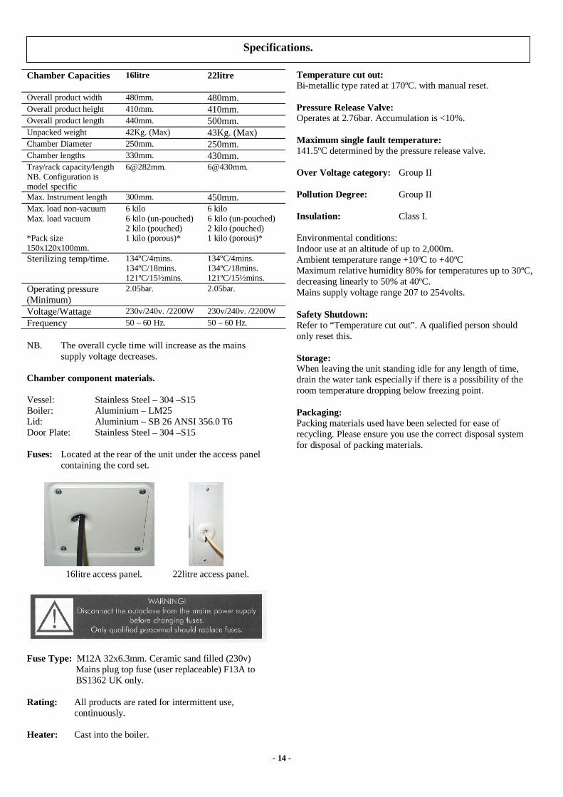
Fuses: Located at the rear of the unit under the access panelcontaining the cord set.
16litre access panel. 22litre access panel.
Fuse Type: M12A 32x6.3mm. Ceramic sand filled (230v)Mains plug top fuse (user replaceable) F13A toBS1362 UK only.
Rating: All products are rated for intermittent use,continuously.
Heater: Cast into the boiler.
Temperature cut out:Bi-metallic type rated at 170ºC. with manual reset.
Pressure Release Valve:Operates at 2.76bar. Accumulation is <10%.
Maximum single fault temperature:141.5ºC determined by the pressure release valve.
Over Voltage category: Group II
Pollution Degree: Group II
Insulation: Class I.
Environmental conditions:Indoor use at an altitude of up to 2,000m.Ambient temperature range +10ºC to +40ºCMaximum relative humidity 80% for temperatures up to 30ºC,decreasing linearly to 50% at 40ºC.Mains supply voltage range 207 to 254volts.
Safety Shutdown:Refer to “Temperature cut out”. A qualified person shouldonly reset this.
Storage:When leaving the unit standing idle for any length of time,drain the water tank especially if there is a possibility of theroom temperature dropping below freezing point.
Packaging:Packing materials used have been selected for ease ofrecycling. Please ensure you use the correct disposal systemfor disposal of packing materials.
Specifications.

- 15 -
The above profile is for the 134ºC /4min Vacuum cycle.
The only difference between this and the 134ºC /18min. Vacuum cycle is the sterilizing hold time. Stage 7 to 8.
The 134ºC /4min. Steam penetration test is identical to the above profile but without the drying (Stage 9 to 10).
ProgrammeStep
Timem:s
Temperature(Measured Value)
Pressure(Measured Value)
Cycle identification.
START 00:001 02:00
TypicalPoint 1340 mbar abs.
1 to 2 02:00Typical
2 to 3 08:00Typical
Point 32·75 bar abs.
3 to 4 07:30Typical
Point 4500 mbar abs.
4 to 5 05:30Typical
Point 52·75 bar abs.
5 to 6 07:30Typical
Point 6500 mbar abs.
6 to 7 05:30Typical
Point 73.04 bar abs.
7 to 8 04:00Fixed
134 to 137ºC. 3·04 bar abs. to 3·32 bar abs.
8 to 9 01:30Typical.
9 to 10 30:00Fixed.
END 73:30Typical
Cycle Profiles.
“Type B” Pressure profile.

- 16 -
The above profile is for the 134ºC /4min. Rapid vacuum cycle.
ProgrammeStep
Timem:s
Temperature(Measured Value)
Pressure(Measured Value)
CycleIdentification.
START 00:00
1 02:00Typical
Point 1340 mbar abs.
1 to 2 08:00Typical
Point 22.7bar abs.
2 to 3 01:00Typical
Point 31.5bar abs.
3 to 4 02:00Typical
Point 43.04 bar abs.
4 to 5 04:00Fixed.
134 to 137ºC. 3·04 bar abs. to 3·32 bar abs.
5 to 6 04:30Typical
END 21:30Typical.
“Type S” Pressure profile.
1
6
P
54
3
2
1.5bar abs.
2.7bar abs.
Sterilizing.

- 17 -
The profile above is for both these cycles the only difference being in sterilizing (Stage 2 to 3).
ProgrammeStep
Timem:s
Temperature(Measured Value)
Pressure(Measured Value)
Cycle Identification.
START 00:00
1 00:30 & 00:30Typical
Point 1750-mbar abs. in both cases.
1 to 2 08:00 & 06:00Typical
Point 23.04 bar abs. & 2.05 bar abs.
2 to 3 04:00 & 15:30Fixed
134·0 to 137·0ºC.121·0 to 124·0ºC.
3·04 bar abs. to 3·32 bar abs.2.05 bar abs. to 2.25 bar abs.
3 to 4 03:30 & 03:30Typical
END 16:00 & 25:30Typical
Figures inbold.
Figures initalics.
NB. THE CYCLE PROFILES SHOWN ON THIS AND EARLIER PAGES ARE FOR THE 16 LITRE AUTOCLAVE.
22 LITRE AUTOCLAVE TIMES WILL BE MARGINALLY LONGER.
0
“Non Vacuum” Pressure profile.
4
32
1
P
Atmospheric pressure.
750mbar abs.
Sterilizing.

- 18 -