operating instructions manual for “cms mf” dosing pump · for “cms mf” dosing pump this...
TRANSCRIPT
1Read Carefully !
ENGLISH Version
R2-01-07
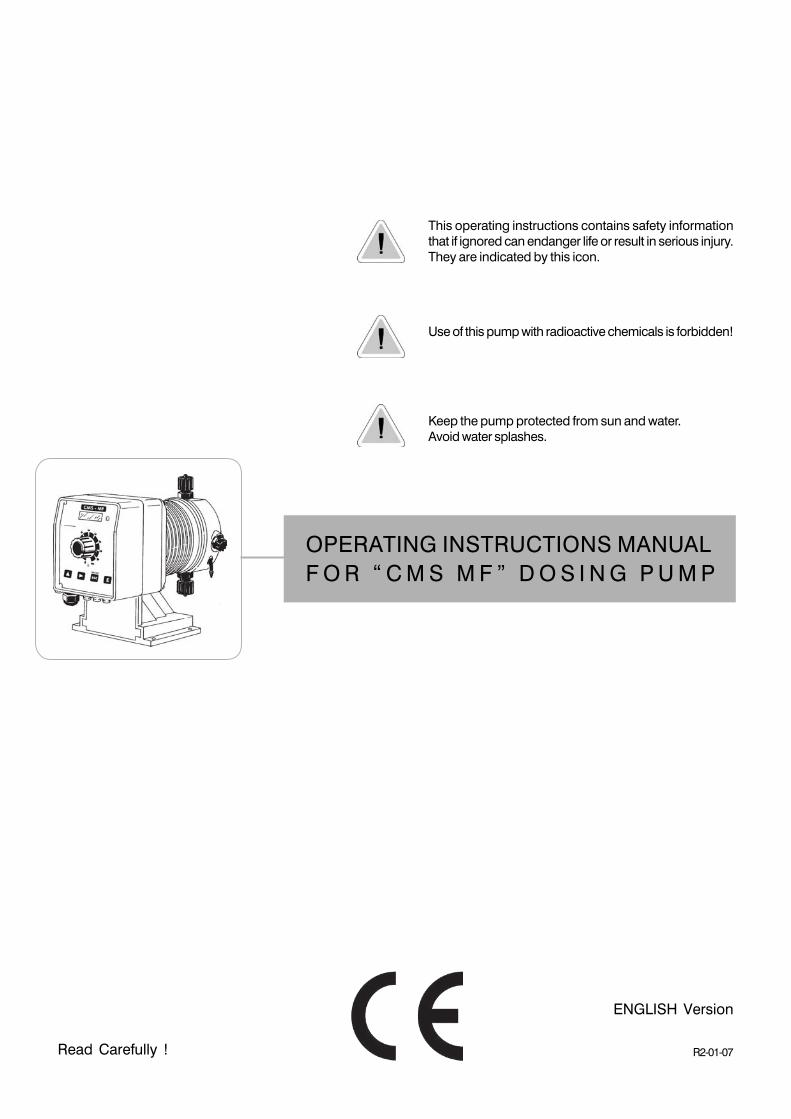
OPERATING INSTRUCTIONS MANUALF O R “ C M S M F ” D O S I N G P U M P
This operating instructions contains safety informationthat if ignored can endanger life or result in serious injury.They are indicated by this icon.
Use of this pump with radioactive chemicals is forbidden!
Keep the pump protected from sun and water.Avoid water splashes.
2
Danger!
GENERAL SAFETY GUIDELINES
In emergencies the pump should be switched off immediately! Disconnect thepower cable from the power supply!
When using pump with aggressive chemicals observe the regulations concerningthe transport and storage of aggressive fluids!
When installing always observe national regulations!
Manufacturer is not liable for any unauthorized use or misuse of this product thatmay cause injury, damage to persons or materials.
Caution!
“CMS MF” series solenoid dosing pumps comply with the following Europeanregulations:
EN60335-1 : 1995, EN55014, EN50081-1/2, EN50082-1/2, EN6055-2, EN60555,3
Based on directive CEE 73/23 c 93/68 (DBT Low voltage directive) and directive 89/336/CEE (EMC Electromagnetic Compatibility)
Pump must be accessible at all times for both operating and servicing. Access mustnot be obstructed in any way!
Feeder should be interlocked with a no-flow protection device.
Pump and accessories must be serviced and repaired by qualified and authorizedpersonnel only!
Always discharge the liquid end before servicing the pump!
Empty and rinse the liquid end before work on a pump which has been used withhazardous or unknown chemicals!
Always read chemical safety datasheet!
Always wear protective clothing when handling hazardous or unknown chemicals!
3
1. Introduction
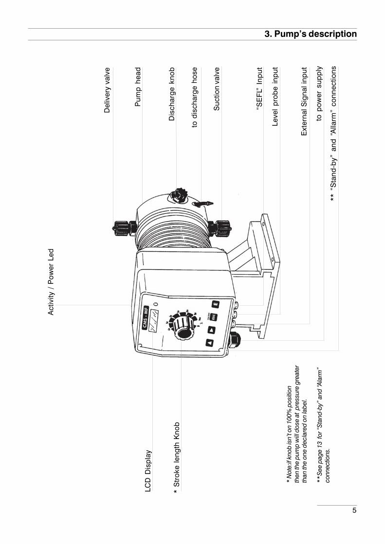
Introduction:Metering Pumps “CMS MF” Series are the ideal solution for low / middle dosing of chemicals. Allcontrol and setup parameters are available through a digital keyboard and they are displayedon a LCD backlit display. Pump has: “Standby” input, “SEFL” input, “LEVEL” input and “Alarm”(contact) output. Note: “SEFL” not included.
Pump’s capacity
Flow rate is determined by the stroke length and by the stroke speed. The stroke length isadjustable from 0 to 100% using the stroke length adjustment knob. However dosing accuracyis guarantee within an adjustment range from 30% to 100%.
Working modes:
Pump can work in differents ways.See related chapters for extended description of each single mode.
CONSTANT mode.Pump doses at a constant rate set in “SPH” (strokes for hour), “SPM” (strokes forminute) or “LPH” (litres per hour) parameters set during program session.
DIVIDE mode.External pulses from a water meter are divided by a value set during program session. The pumpdoses with a rate determined by this parameter.
MULTIPLY mode.External pulses from a water meter are multiplied by a value set during program session. The pumpdoses with a rate determined by this parameter.
PPM mode.Dosing rate is determined by pulses from a water meter on the base of set PPM, chemical productconcentration (%) and quantity for each single stroke set during program session.
PERC modeDosing rate is determined by pulses from a water meter on the base of set PERC (%), chemicalproduct concentration (%) and quantity for each single stroke set during program session.
MLQ modeDosing rate is determined by pulses from a water meter on the base of set MLQ (milliliters perquintal), chemical product concentration (%) and quantity for each single stroke set during programsession.
BATCH mode.Signal from an external contact starts the pump to dose the set quantity.
VOLT mode.Voltage from an external device drives the pump that doses proportionally using a minimum andmaximum of strokes for minute set during program session.
mA mode.Current from an external device drives the pump that doses proportionally using a minimum andmaximum of strokes for minute set during program session.
4
2. Unpacking
Included into package:
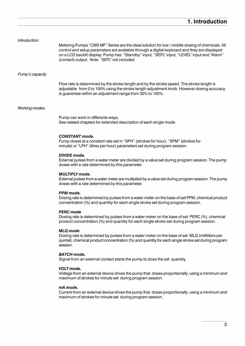
n.4 Dibbles ø6n.4 Self tapping screws 4,5 x 40n.1 Delayed fuse 5 X 20n.1 Foot filter with valven.1 Injection valven.1 Level probem 2 Delivery pipe* (opaque PE)m 2 Suction pipe * (transparent PVC)m 2 Discharge pipe (transparent PVC)m 2,5 Signal cable for “Stand-by” and “Alarm”n.1 This installation manual
* If hose is 6x8 there is only a 4meters long hose.Cut to obtain suction and delivery hoses.
Remove the contents from the box.
PLEASE DO NOT TRASH PACKAGING.IT CAN BE USED TO RETURN THE PUMP.
5
3. Pump’s description
* S
trok
e le
ngth
Kno
b
* N
ote:
if kn
ob is
n’t o
n 10
0% p
ositi
onth
en th
e pu
mp
will
dos
e at
pre
ssur
e gr
eate
rth
an th
e on
e de
clar
ed o
n la
bel.
**Se
e pa
ge 1
3 fo
r “St
and-
by”
and
“Ala
rm”
conn
ectio
ns.
** “
Sta
nd-b
y” a
nd “
Alla
rm”
conn
ectio
ns
Del
iver
y va
lve
Act
ivity
/ P
ower
Led
Suc
tion
valv
e
to d
isch
arg
e ho
se
Dis
char
ge
knob
to p
ower
sup
ply
Ext
erna
l Sig
nal i
nput
Leve
l p
rob
e in
put
Pum
p h
ead
LCD
Dis
pla
y
“SE
FL”
Inp
ut
6
4. Before to Install warnings
Pump’s installation and operativity is made in 4 main steps:
Pump’s installation
Hydraulic Installation (hoses, level probe, injection valve)
Electrical Installation (main power connection, SEFL installation, priming)
Programming the pump.
Before to start, please read carefully the following safety information.
Protective clothes
Wear always protective clothes as masks, gloves, safety glasses andfurther security devices during ALL installation procedure and whilehandling chemicals.
Installation location
Pump must be installed in a safety place and fixed to the table / wall toavoid vibration problems!
Pump must be installed in a easy accessible place!
Pump must be installed in horizontal position!
Avoid water splashes and direct sun!
Hoses and Valves
Suction and delivery hoses must be installed in horizontal position!All hoses connections must be performed using only hands’ force!No tongs required!
Delivery hose must be firmly fixed to avoid suddenly movementsthat could damage near objects!
Suction hose must be shorter as possible and installed in verticalposition to avoid air bubbles suction!
Use only hoses compatibles with product to dose! See chemicalcompatibility table at page 49. If dosing product is not listed pleaseconsult full compatibility table or contact chemical’s manufacturer!
7
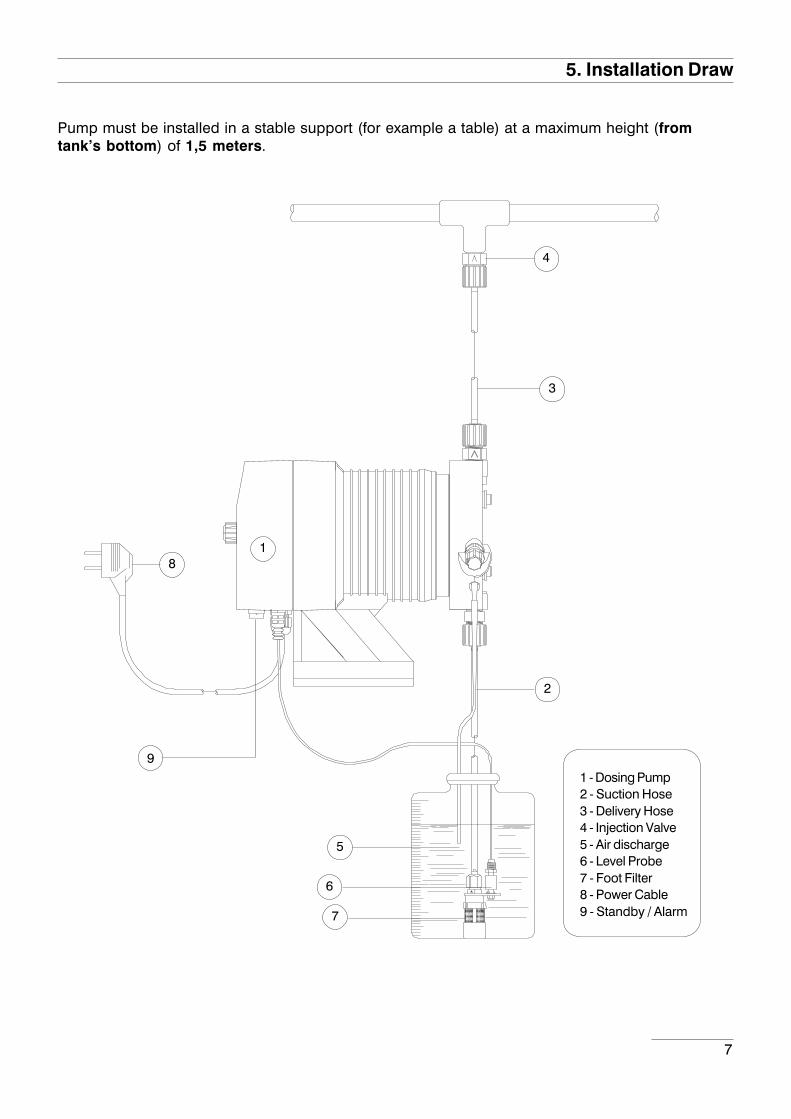
5. Installation Draw
Pump must be installed in a stable support (for example a table) at a maximum height (fromtank’s bottom) of 1,5 meters.
1 - Dosing Pump2 - Suction Hose3 - Delivery Hose4 - Injection Valve5 - Air discharge6 - Level Probe7 - Foot Filter8 - Power Cable9 - Standby / Alarm
1
5
6
7
8
9
2
3
4

8
6. Hydraulic Installation
Suction Hose
Tightening Nut
Holding Ring
Pipe Holder
O-ring
Valve
Hydraulic connections are:
Suction Hose with level probe and foot filterDelivery Hose with injection valve
Discharge Hose
Suction Hose.
Completely unscrew tightening nut from pump’s head and remove assemblingcomponents: tightening nut, holding ring and pipe holder.
Assembly as shown in fig. (A). Insert hose into pipe holder until it reaches thebottom.
Lock hose on pump’s head by screwing down the tightening nut.Use only hands to do it!
Connect other side of the hose to the foot filter using the same procedure.
fig. (A)
9
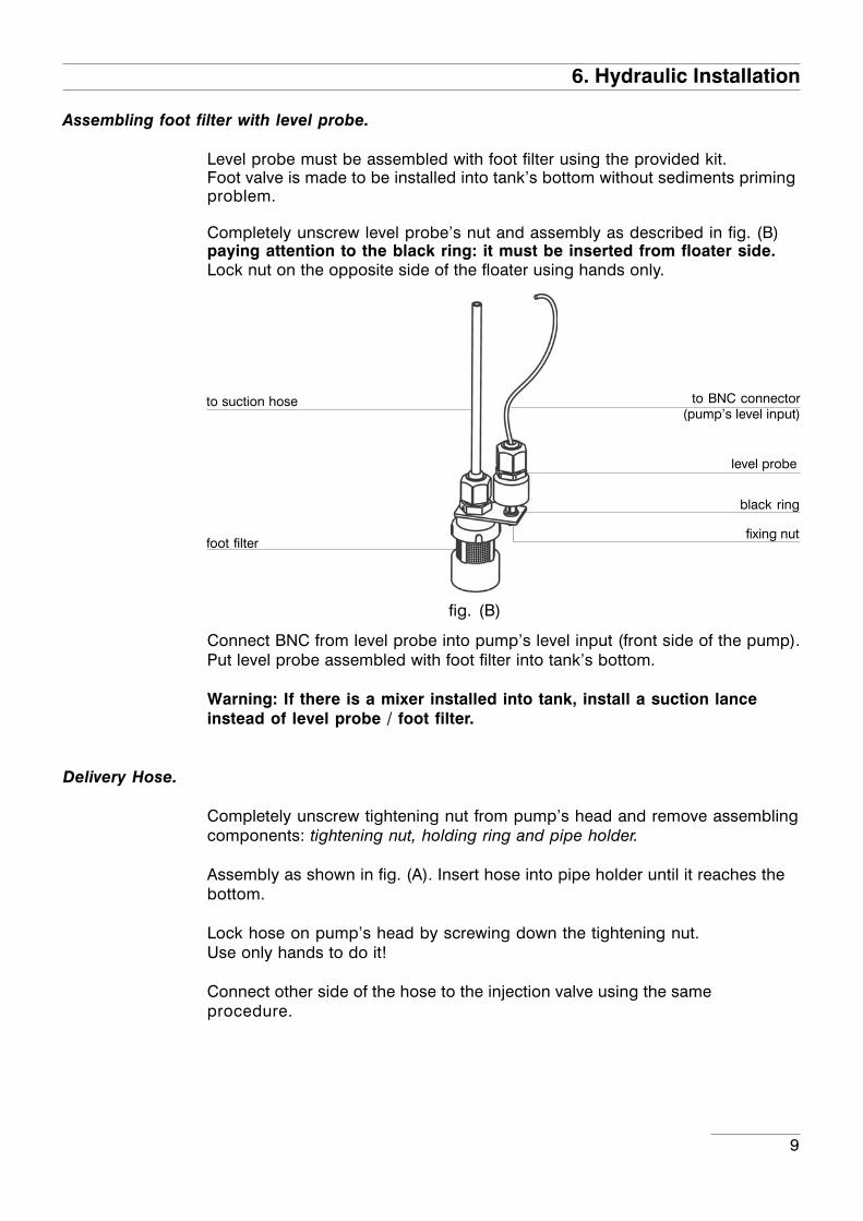
Assembling foot filter with level probe.
Level probe must be assembled with foot filter using the provided kit.Foot valve is made to be installed into tank’s bottom without sediments primingproblem.
Completely unscrew level probe’s nut and assembly as described in fig. (B)paying attention to the black ring: it must be inserted from floater side.Lock nut on the opposite side of the floater using hands only.
Connect BNC from level probe into pump’s level input (front side of the pump).Put level probe assembled with foot filter into tank’s bottom.
Warning: If there is a mixer installed into tank, install a suction lanceinstead of level probe / foot filter.
Delivery Hose.
Completely unscrew tightening nut from pump’s head and remove assemblingcomponents: tightening nut, holding ring and pipe holder.
Assembly as shown in fig. (A). Insert hose into pipe holder until it reaches thebottom.
Lock hose on pump’s head by screwing down the tightening nut.Use only hands to do it!
Connect other side of the hose to the injection valve using the sameprocedure.
fig. (B)
6. Hydraulic Installation
to BNC connector(pump’s level input)
level probe
foot filter
to suction hose
black ring
fixing nut

10
6. Hydraulic Installation
Tubo di spurgo.
Insert one side of discharge hose into discharge connector as shown in fig (C).
Insert other side of discharge hose into product’s tank.During priming procedure product exceeding will flow into tank.
For priming procedure see page 16.
Discharge hose
Discharge Knob
fig (C)
Injection Valve.
Injection valve must be installed on plant from water’s input.Injection valve will open at pressure greater than 0,3bar.

11
6. Hydraulic Installation
Self-venting pump head.
Self-venting pump head must be used when using chemicals that producegas (i.e. hydrogen peroxide, ammonium, sodium hypoclorite at particularconditions).
Hoses assembling procedure (including purge hose) is described in fig. (A).
Notes:
- suction, delivery and purge valves are DIFFERENT! Do not exchange them!
- delivery and purge hoses are made of same material!
- it’s allowed to lightly bend discharge hose!
- during calibration procedure (“TEST”) insert discharge hose into BECKER test-tube!
to bleed hose
to suction hose
to delivery hose
12
7. Electrical Installation
All electrical connections must be performed by AUTHORIZED AND QUALIFIED personnel only.Before to proceed, please, verify the following steps:
- verify that pump’s label values are compatible with main power supply.
- pump must be connected to a plant with a differential switch (0,03Asensitivity) if there isn’t a good ground.
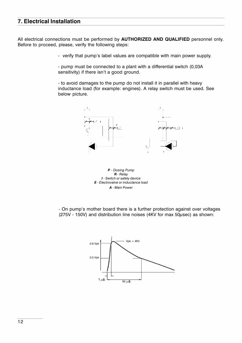
- to avoid damages to the pump do not install it in parallel with heavyinductance load (for example: engines). A relay switch must be used. Seebelow picture.
P - Dosing PumpR - Relay
I - Switch or safety deviceE - Electrovalve or inductance load
A - Main Power
- On pump’s mother board there is a further protection against over voltages(275V - 150V) and distribution line noises (4KV for max 50µsec) as shown:
13
7. Electrical Installation
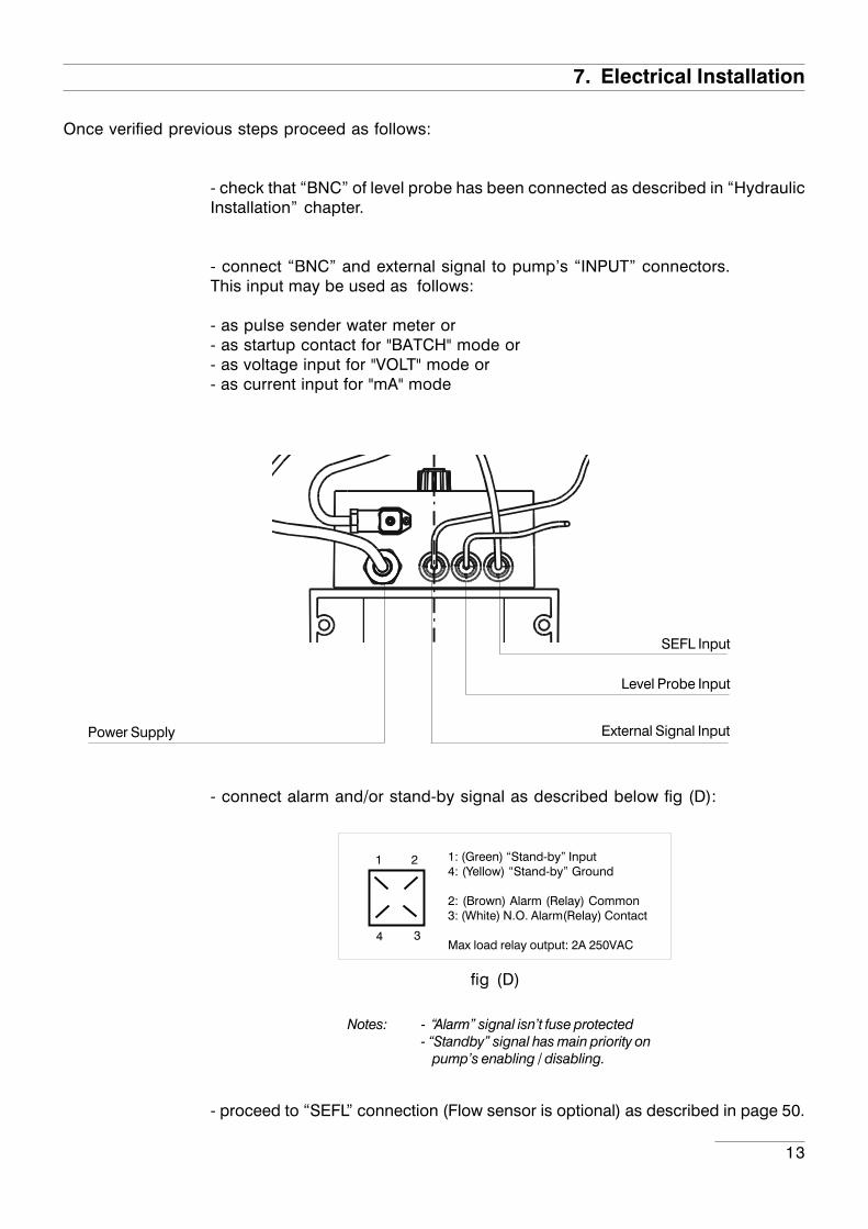
Once verified previous steps proceed as follows:
- check that “BNC” of level probe has been connected as described in “HydraulicInstallation” chapter.
- connect “BNC” and external signal to pump’s “INPUT” connectors.This input may be used as follows:
- as pulse sender water meter or- as startup contact for "BATCH" mode or- as voltage input for "VOLT" mode or- as current input for "mA" mode
- connect alarm and/or stand-by signal as described below fig (D):
- proceed to “SEFL” connection (Flow sensor is optional) as described in page 50.
fig (D)
1
4
1: (Green) “Stand-by” Input4: (Yellow) “Stand-by” Ground
2: (Brown) Alarm (Relay) Common3: (White) N.O. Alarm(Relay) Contact
Max load relay output: 2A 250VAC
2
3
Notes: - “Alarm” signal isn’t fuse protected- “Standby” signal has main priority on pump’s enabling / disabling.
External Signal Input
Level Probe Input
Power Supply
SEFL Input

14
CMS MFCMS MFCMS MFCMS MFCMS MF
8. Basic Settings
LCD backlit display
Storke Lenght Knob
Scroll and increase digit
Turn the pump on or off and exit from setup menu (without saving parameters)
Enter / exit from setup menu (saving parameters)
The “CMS MF” pump is equipped with a keyboard.To avoid any misunderstanding during next chaptersall keys will be described as shown on this legend:
“UP” key “ESC” key
“RIGHT” key “E” key
Menu navigation:
To enter into programming mode press and keep pressed “E” key from main screen (fig.3):
After about 4 seconds the pump will show the password screen (fig.5):
Default password is “0000”. Just press “E” key. Otherwise insert password using “UP” and “RIGHT”keys.
E
ESC
STROKES 100 SPM fig.3
password 0000 fig.5
ON/OFF
15
8. Basic Settings
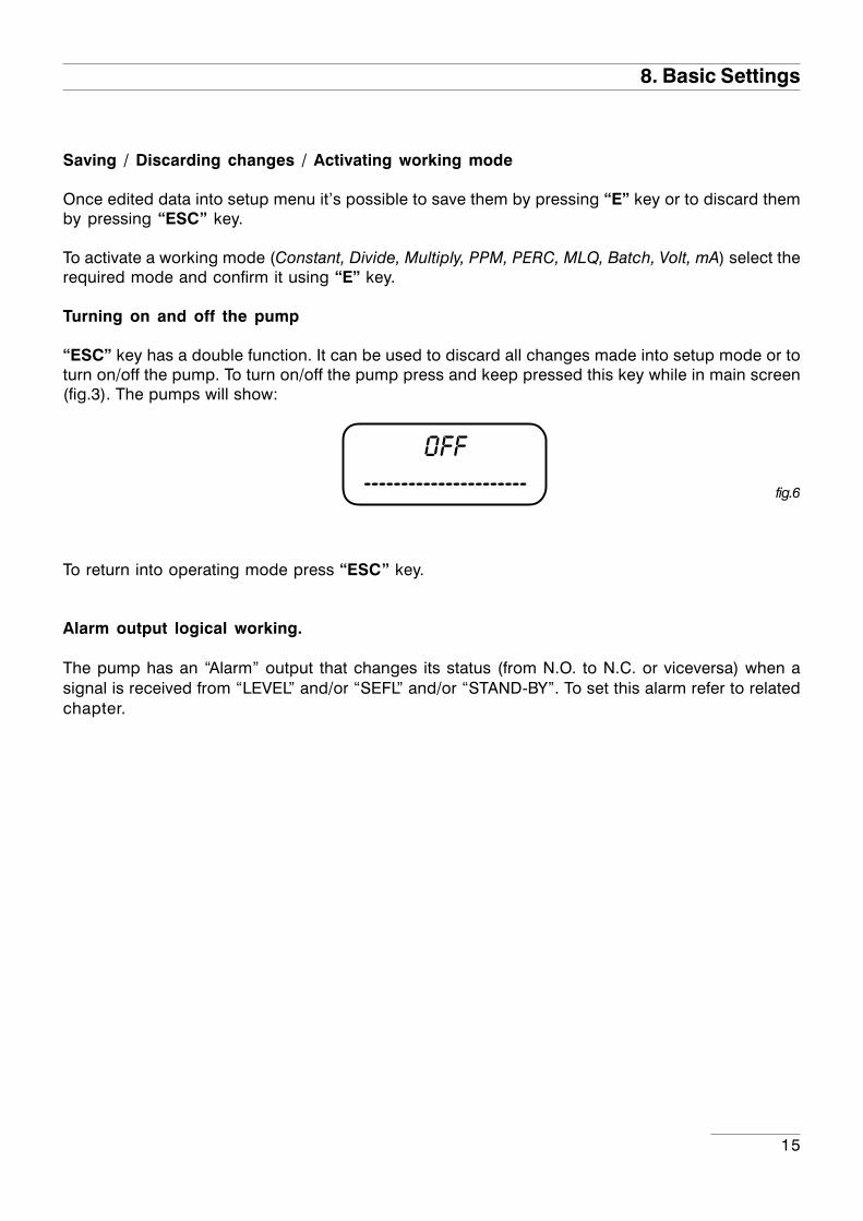
OFF----------------------
Saving / Discarding changes / Activating working mode
Once edited data into setup menu it’s possible to save them by pressing “E” key or to discard themby pressing “ESC” key.
To activate a working mode (Constant, Divide, Multiply, PPM, PERC, MLQ, Batch, Volt, mA) select therequired mode and confirm it using “E” key.
Turning on and off the pump
“ESC” key has a double function. It can be used to discard all changes made into setup mode or toturn on/off the pump. To turn on/off the pump press and keep pressed this key while in main screen(fig.3). The pumps will show:
To return into operating mode press “ESC” key.
Alarm output logical working.
The pump has an “Alarm” output that changes its status (from N.O. to N.C. or viceversa) when asignal is received from “LEVEL” and/or “SEFL” and/or “STAND-BY”. To set this alarm refer to relatedchapter.
fig.6
16
9. Priming
the pump will show the “Delay” (pump’s activation delay) as shown fig.2:
Press any key to skip the “Delay”. Pump will show “Srokes” (actual strokes) as shown in fig.3:
In any working mode, if a SEFL is installed and enabled (see SEFL Setup procedure), the display willshow the icon (asterisk as in fig. 4):- if SEFL works correctly, the asterisk blinks to any pulses given by the solenoid;- if the asterisk does not appear, there is an anomaly (i.e.: hoses and/or valves are obstructed, SEFLin not connected, etc.).
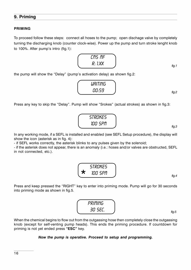
Press and keep pressed the “RIGHT” key to enter into priming mode. Pump will go for 30 secondsinto priming mode as shown in fig.5.
When the chemical begins to flow out from the outgassing hose then completely close the outgassingknob (except for self-venting pump heads). This ends the priming procedure. If countdown forpriming is not yet ended press “ESC” key.
Now the pump is operative. Proceed to setup and programming.
fig.1
fig.2
fig.3
fig.4
PRIMING
To proceed follow these steps: connect all hoses to the pump; open dischage valve by completely
turning the discharging knob (counter clock-wise). Power up the pump and turn stroke lenght knob
to 100%. After pump’s intro (fig.1):
*
cMS MFR: 1.xx
WAITING00:59
STROKES 100 SPM
STROKES 100 SPM
PRIMING 30 Sec. fig.5
17
10. Pump’s functions summary
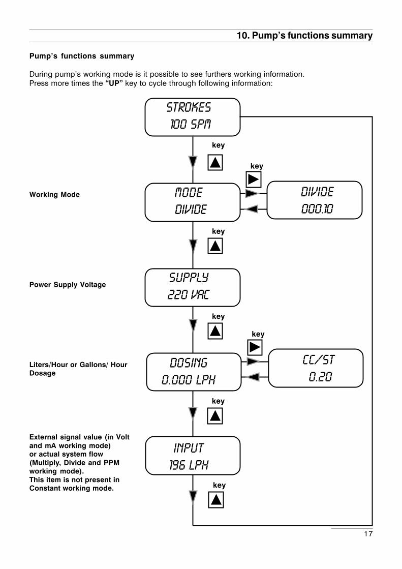
Pump’s functions summary
During pump’s working mode is it possible to see furthers working information.Press more times the “UP” key to cycle through following information:
key
key
key
Working Mode
Power Supply Voltage
key
key
divide000.10
key
cc/st 0.20
External signal value (in Voltand mA working mode)or actual system flow(Multiply, Divide and PPMworking mode).This item is not present inConstant working mode. key
STROKES 100 SPM
MODE divide
SUPPLY220 VAC
DOSING0.000 lph
input196 lph
Liters/Hour or Gallons/ HourDosage

18
This diagram showsall the possible
alarms.
ALARMLEVEL
Key
ALARMSEFL
Key
ALARMSTD-By
Key
overflow
Key
Key
ALARMstroke
ALARMPOWER
Key
10. Pump’s functions summary- ALARMS
If any alarm is active, in the menù “Pump’s functions summary” a general alarm display will showthe number of alarm active at the moment. Enter into this menu with “RIGHT” key.The windows displayed show which alarms are active.
Level alarm: the level probe signals theproduct end.
SEFL alarm signals an anomaly for theSEFL.
Stand-by alarm signals the pump stop.
Over flow alarm (when using “Divide”,“Multiply”, “ppm” working mode): signalsthe working frequency of the pump ishigher than the values on the label.
Power alarm signals the power supply isout of range (from 180 to 260 VAC).
Stroke alarm signals that it has been set acapacity higher than the value on the label.
Key
ALARMbatch
Key
Batch alarm signals that the pumps hasreceived a pulse while in Batch workingmode.
ALARMN° 01
STROKES 100 SPM
SUPPLY220 VAC
DOSING0.000 lph
Key
Key
Key
Key
Key
input196 lph
Key
MODE divide

19
11. Quick Guide - Main Menu (Prog [1] Mode)
Key
PROG [2]SETUP
PROG [3]STAT
Key
EKey
EKey
Seepage 19
EKey
Seepage 20
Key
PROG [1]MODE E
E
E
E
E
E
E
Mode [7]BATCH
Mode [2]DIVIDE
Mode [4]PPM
Mode [8]VOLT
Mode [9]mA
Key
KeySeepage 35
KeySeepage 36
Key
Key
Seepage 40
KeySeepage 41
KeySeepage 42
Key
Key
Key
Key
Key
Key
Key
Mode [1]CONSTANT
Mode [3]MULTIPLY
Seepage 34
Seepage 37
E
E
Mode [5]PERC
Mode [6]MLQ
Key
Seepage 38
KeySeepage 39Key
Key

20
12. Quick Guide - Main Menu (Prog [2] Setup)
EKey
EKey
EKey
Key
Key
Key
PROG [1]MODE
PROG [2]SETUP
PROG [3]STAT
Seepag. 19
See pag. 21
E
E
E
E
E
E
E
E
E
E
E
SET [01]CC/ST
Set [02]test
set [03]level
set [04]Sefl
set [05]Stand-by
set [07]alarms
set [08]wmeter
set [09]timeout
set [10]unit
key
set [12)password
key
key
key
key
key
key
key
keySeepag. 22
keySeepag. 22
keySeepag. 23
key
Seepag. 24
keySeepag. 24
keySeepag. 25
key
Seepag. 25
keySeepag. 26
keySeepag. 27
keySeepag. 27
keySeepag. 28
key
set [11)delay
key
E
set [06]out al
key
keySeepag. 24
key

21
13. Quick Guide - Main Menu (Prog [3] Stat)
See pag. 18
EKey
EKey
See pag. 19
E
See pag. 38
Key
Key
Key
Key
PROG [1]MODE
PROG [3]STAT
PROG [2]SETUP
->TOt dos counter

22
15. Setup
Pump’s initial setupApart of choosen working mode, the pump must be prepared to operate by setting the mainparameters into “SETUP” menu. To enter into this menu please follow the “Quick Guide throughmenu” at page 20.
CC per Stroke.
Enter here the cc/stroke value obtained during “Test” mode(calibration).
Use “UP” key to increase of one unit the blinking digit “_”.
Press “RIGHT” key to skip on next digit.
Press “E” key to save data and “ESC” exit to main menu.Otherwise press “ESC” to discard data and exit to mainmenu.
SET [01]CC/ST
CC/ST10.00
KeyE
SET [02]TEST
Calibration.
This procedure defines the cc quantity (cubical centimeters) thatthe pump feed every single injection. To determine this value thepump must be calibrated.
1) Install the pump on plant and insert the suction hose (with itslevel probe / foot filter) into a BEKER “test-tube”.If pump’s model is self-priming put the discharge hose into the“test-tube“ too.
2) Power up the pump and turn the flow’s knob to required position.
3) Fill up the “test-tube” with the chemical until to reach a knownvalue.
4) From setup menu choose “TEST”, and insert 20”. This value is thestrokes that the pump will produce during the procedure.
6) Press “E”. The pump will begin to produce the 20 strokes and tosuck the chemical from the “test-tube”.
7) At the end of 20 strokes the pump will stop. Read the value ofchemical left into “test-tube”.
8) Substract the initial value to the left value.
9) Divide the result with the ST value (20).
10) Type this value into “CC/ST” (Set [01]) as previously described.
11) If obtained result is too small or too big, please, try to changestrokes value (20).
TEST ONST 020
TEST OFFST 020
KeyE
23
15. Setup
123456789012345678901123456789012345678901123456789012345678901123456789012345678901123456789012345678901123456789012345678901123456789012345678901123456789012345678901123456789012345678901123456789012345678901123456789012345678901123456789012345678901123456789012345678901123456789012345678901123456789012345678901123456789012345678901123456789012345678901
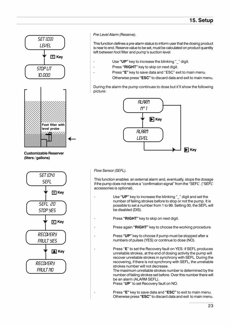
Pre Level Alarm (Reserve).
This function defines a pre-alarm status to inform user that the dosing productis near to end. Reserve value to be set, must be calculated on product quantityleft between foot filter and pump’s suction level.
- Use “UP” key to increase the blinking “_” digit.- Press “RIGHT” key to skip on next digit.- Press “E” key to save data and “ESC” exit to main menu.
Otherwise press “ESC” to discard data and exit to main menu.
During the alarm the pump continues to dose but it’ll show the followingpicture:
SET [03]LEVEL
stop LIT10.000
KeyE
Customizable Reserver(liters / gallons)
1234567890123456789012345678901212345678901234567890123456789012123456789012345678901234567890121234567890123456789012345678901212345678901234567890123456789012123456789012345678901234567890121234567890123456789012345678901212345678901234567890123456789012123456789012345678901234567890121234567890123456789012345678901212345678901234567890123456789012
Foot filter withlevel probe
ALARMN° 1
ALARMLEVEL
Key
Key
Flow Sensor (SEFL).
This function enables an external alarm and, eventually, stops the dosageif the pump does not receive a “confirmation signal” from the “SEFL”. (“SEFL”accessories is optional).
- Use “UP” key to increase the blinking “_” digit and set thenumber of failing strokes before to stop or not the pump. It ispossible to set a number from 1 to 99. Setting 00, the SEFL willbe disabled (DIS).
- Press “RIGHT” key to skip on next digit.
- Press again “RIGHT” key to choose the working procedure.
- Press “UP” key to choose if pump must be stopped after anumbers of pulses (YES) or continue to dose (NO).
- Press “E” to set the Recovery fault on YES: if SEFL producesunreliable strokes, at the end of dosing activity the pump willrecover unreliable strokes in synchrony with SEFL. During therecovering, if there is not synchrony with SEFL, the unreliablestrokes number will not decrease.The maximum unreliable strokes number is determined by thenumber of failing strokes set before. Over this number there willbe an alarm (ALARM SEFL).Press “UP” to set Recovery fault on NO.
- Press “E” key to save data and “ESC” to exit to main menu.Otherwise press “ESC” to discard data and exit to main menu.
Key
SET [04]SEFL
E
E
recoveryfault no
recoveryfault yes
Key
Key
SEFL 20stop yes
24
15. Setup
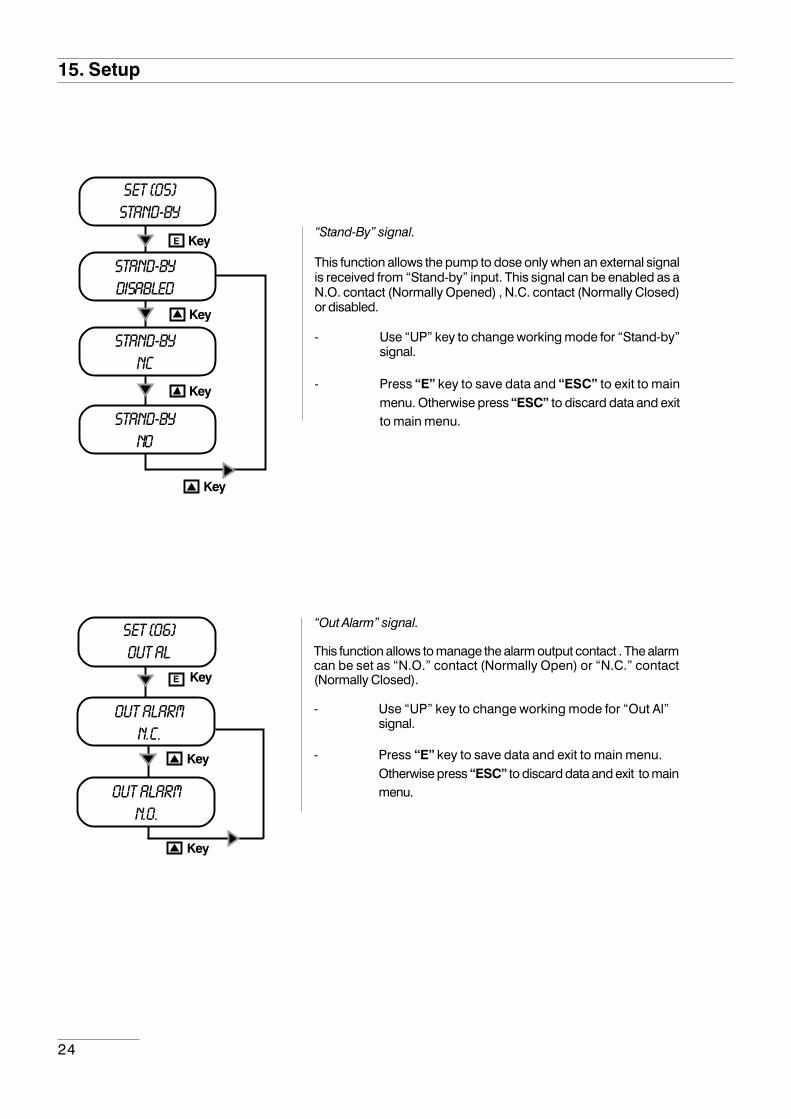
“Stand-By” signal.
This function allows the pump to dose only when an external signalis received from “Stand-by” input. This signal can be enabled as aN.O. contact (Normally Opened) , N.C. contact (Normally Closed)or disabled.
- Use “UP” key to change working mode for “Stand-by”signal.
- Press “E” key to save data and “ESC” to exit to mainmenu. Otherwise press “ESC” to discard data and exitto main menu.
SET [05]Stand-by
STand-bydisabled
Key
STand-byNC
Key
Key
STand-byNO
Key
E
SET [06]out al
out alarmn.c.
E
Key
Key
Key
out alarmn.o.
“Out Alarm” signal.
This function allows to manage the alarm output contact . The alarmcan be set as “N.O.” contact (Normally Open) or “N.C.” contact(Normally Closed).
- Use “UP” key to change working mode for “Out Al”signal.
- Press “E” key to save data and exit to main menu.Otherwise press “ESC” to discard data and exit to mainmenu.

25
15. Setup
Alarms Management.
Use this function to enable/disable the relay output for level alarm(lev) and/or standby (stby) and/or flow sensor (sefl) and/or ppmand/or percentage (PERC) and/or MLQ and/or Batch.
If alarm is activated for one or more events then the output relay willbe enabled, the pump will show the alarm status and it’ll stop or notthe dosing activity.
If alarm is not activated for one or more events then the output relaywill be disabled, the pump will show the alarm status and it’ll stop ornot the dosing activity.
- Use “UP” key to choose the alarm to set.
- Use “RIGHT” key to enable (EN) or disable (DI) the alarm.
- Press “E” key to save data and “ESC” to exit to mainmenu. Otherwise press “ESC” to discard data and exitto main menu.
SET [07]aLARMS
ALARM[1]LEV EN
Key
ALARM[2]stby EN
Key
Key
alarm[3]sefl en
Key
E
Key
alarm[4]ppm en
Key
alarm[5]PERC
Key
alarm[6]MLQ
Key
alarm[7]BATCH
26
15. Setup
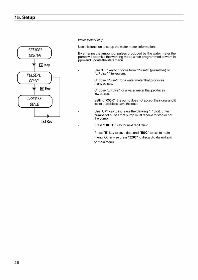
Water Meter Setup.
Use this function to setup the water meter information.
By entering the amount of pulses produced by the water meter thepump will optimize the working mode when programmed to work inppm and update the stats menu.
- Use “UP” key to choose from “Pulse/L” (pulse/liter) or“L/Pulse” (liter/pulse).
Choose “Pulse/L” for a water meter that producesmany pulses.
Choose “L/Pulse” for a water meter that producesfew pulses.
Setting “000.0”, the pump does not accept the signal and itis not possible to save the data.
- Use “UP” key to increase the blinking “_” digit. Enternumber of pulses that pump must receive to stop or notthe pump.
- Press “RIGHT” key for next digit / field.
- Press “E” key to save data and “ESC” to exit to mainmenu. Otherwise press “ESC” to discard data and exitto main menu.
SET [08]wmeter
pulse/l004.0
Key
l/pulse004.0
Key
E
Key

27
15. Setup
Pulses Timeout (only for “Multiply” working mode and “PPM”,“PERC” and “MLQ” working mode when the result is a multiplication).
When the pump receives a pulse from the water meter it starts thedosing activity through an amount of time (from the first pulse tothe following one).At the beginning the pump doesn’t know the time lapse betweenthe first and the second pulse. So it’ll dose the product in the fastestway. From the second pulse, the pump will dose the productcorrectly.
This function set the maximum time between a pulse and thefollowing one. Once that this time is exceeded the pump willreinitialize the dosing activity as the first time that a pulse has beenreceived.
Default value is 120 seconds.To set “Timeout” function, between the minimum (1 sec.) and themaximum (999 sec.), proceed as follow:
- Use “UP” key to increase the blinking “_” digit. Enternumber of pulses that pump must receive to stop or notthe pump.
- Press “RIGHT” key for next digit / field.
- Press “E” key to save data and “ESC” to exit to mainmenu. Otherwise press “ESC” to discard data and exitto main menu.
Pulses Timeout does not take part in “Divide” working mode andin all working modes when the result is a division.
SET [09]timeout
timeout020 sec
KeyE
External Pulses
The first time that the pump receives a pulse itdoesn’t know the the time between this pulse andthe following one. So the pump will run faster aspossible. “Timeout” function forces the pump towork in this way, once a specified amount of timehas been exceeded.
After second pulse the pump will know the timebetween a pulse and the following one.
So it’ll dose optimizing the dosage through thetime.

28
15. Setup
SET [10]unit
UNITlitre
KeyE
Unit Change.
This function allows to choose between liters or gallonsmeasurement unit.
- Use “UP” key to switch between liter or gallonsmeasurement unit.
- Press “E” key to save data and “ESC” to exit to mainmenu. Otherwise press “ESC” to discard data and exitto main menu.
unitusgal
Key
Key
SET [11]delay
power on01 min
KeyE
Startup Delay Setup.
When the pump is powered is it possible to have a delay time (from0 to 10 minutes) before dosing activities.
- Use “UP” key to choose the alarm to set.
- Use “RIGHT” key for next digit.
- Press “E” key to save data and “ESC” to exit to mainmenu. Otherwise press “ESC” to discard data and exitto main menu.
Note: Press any key during delay time to skip it.

29
SET [12]password
password0000
KeyE
Password Setup.
“Setup” menu is password protected. Default value to enter into“setup” menu is “0000” (only numeric units). To change thispassword proceed as follows:
- Use “UP” key to change first digit.
- Press “RIGHT” key to move cursor over next digit.
- Press “E” key to save data and “ESC” to exit to mainmenu. Otherwise press “ESC” to discard data and exitto main menu.
Note: For lost password, please, follow the “Load default”procedure.
15. Setup
30
“LOAD DEFAULT” procedure
This procedure deletes all programming data set. It reloads the default data of the pump.
Follow this instructions:
- unplug power supply;
- pressing both “UP” and “RIGHT” keys, plug in power supply.
For few seconds, the display shows LOAD DEFAULT before start up the pump.
16. “Load default” and “Reset Password” procedure
“RESET PASSWORD” procedure
This procedure resets the password set and reloads the default password of the pump (“0000”).
Follow this instructions:
- unplug power supply;
- pressing both “UP” and “ESC” keys, plug in power supply.
For few seconds, the display shows RESET PASSWORD before start up the pump.
31
17. Working procedure setup
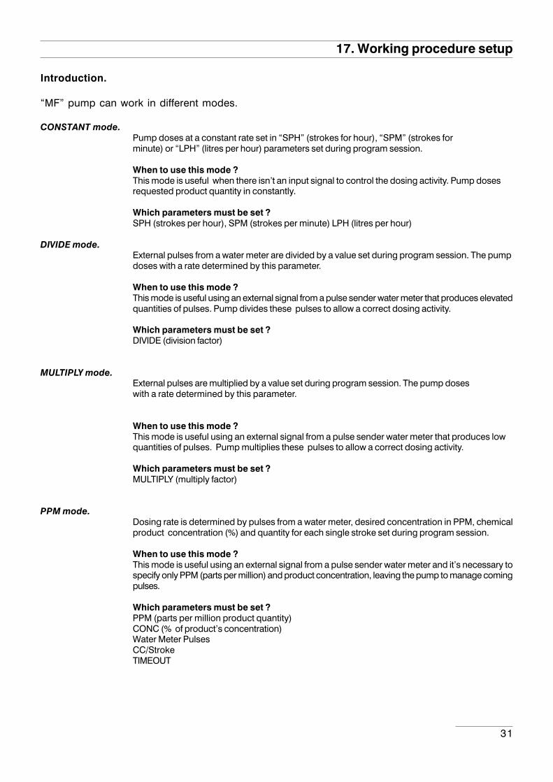
Introduction.
“MF” pump can work in different modes.
CONSTANT mode.Pump doses at a constant rate set in “SPH” (strokes for hour), “SPM” (strokes forminute) or “LPH” (litres per hour) parameters set during program session.
When to use this mode ?This mode is useful when there isn’t an input signal to control the dosing activity. Pump dosesrequested product quantity in constantly.
Which parameters must be set ?SPH (strokes per hour), SPM (strokes per minute) LPH (litres per hour)
DIVIDE mode.External pulses from a water meter are divided by a value set during program session. The pumpdoses with a rate determined by this parameter.
When to use this mode ?This mode is useful using an external signal from a pulse sender water meter that produces elevatedquantities of pulses. Pump divides these pulses to allow a correct dosing activity.
Which parameters must be set ?DIVIDE (division factor)
MULTIPLY mode.External pulses are multiplied by a value set during program session. The pump doseswith a rate determined by this parameter.
When to use this mode ?This mode is useful using an external signal from a pulse sender water meter that produces lowquantities of pulses. Pump multiplies these pulses to allow a correct dosing activity.
Which parameters must be set ?MULTIPLY (multiply factor)
PPM mode.Dosing rate is determined by pulses from a water meter, desired concentration in PPM, chemicalproduct concentration (%) and quantity for each single stroke set during program session.
When to use this mode ?This mode is useful using an external signal from a pulse sender water meter and it’s necessary tospecify only PPM (parts per million) and product concentration, leaving the pump to manage comingpulses.
Which parameters must be set ?PPM (parts per million product quantity)CONC (% of product’s concentration)Water Meter PulsesCC/StrokeTIMEOUT

32
17. Working procedure setupPERC mode.
Dosing rate is determined by pulses from a water meter, percentage (%), chemical product concentrationand quantity for each single stroke set during program session.
When to use this mode ?This mode is useful using an external signal from a pulse sender water meter and it’s necessary tospecify only % , leaving the pump to manage coming pulses.
Which parameters must be set ?% (percentage of product quantity to dose)CONC (% of product’s concentration): set 100% if product is pureWater Meter PulsesCC/Stroke
TIMEOUT
METERING PUMP
PUMP CAPACITY (l/h) = 10 x C (%) x P (m3/h)C: max concentration requiredP: plant capacity at max concentration required
WATER METER
CALIBER: refer to the table
imp/l =72
P (m3/h)
On the table below choose the valueclosest to this result
Pulses per liter table forwater meters
CTFI / CTCI / CTFITCTCIT CTFIG / CTCIG
Water Meter Caliber
15 20 25 30 40 50
Pulses for 1 lt35 - 70
1401 - 2 - 4
22.5 - 4590
1 - 2 - 4
12 - 2448
1 - 2 - 4
12 - 2448
1 - 2 - 4
4,5 - 918
1 - 2 - 41 , 2 , 4
Pulses for 10 lt 1 , 2 , 4 1 , 2 , 4 1 , 2 , 4 1 , 2 , 4 1 , 2 , 4 1 , 2 , 4
Pulses for 100 lt 1 , 2 , 4 1 , 2 , 4 1 , 2 , 4 1 , 2 , 4 1 , 2 , 4 1 , 2 , 4
Pulses for 1000 lt 1 , 2 , 4 1 , 2 , 4 1 , 2 , 4 1 , 2 , 4 1 , 2 , 4 1 , 2 , 4
Gaugemminch
151/2
203/4
251
301.1/4
401.1/2
502
Inertial breaking l/h 10 15 20 20 25 50
Max temporary flow delivery m3/h 3 5 7 10 20 30
Flow delivery with 10m of load loss m3/h 3 5 7 10 20 30
Nominal flow rate m3/h 1.5 2.5 3.5 5 10 15
First precision delivery ±5% l/h 30 50 70 100 200 450
Second precision delivery ±2% l/h 120 200 280 400 800 3000
Max operation pressure bar 16 16 16 16 16 16
Minimum reading l 0.1 0.1 0.1 0.1 0.1 0.5
Maximum reading m3 105 105 105 105 105 106
Turbine revs per liter g/l 34.8 22.5 11.7 11.7 4.5 3.16
33
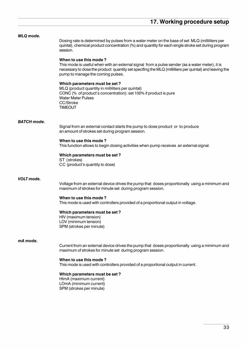
MLQ mode.Dosing rate is determined by pulses from a water meter on the base of set MLQ (milliliters perquintal), chemical product concentration (%) and quantity for each single stroke set during programsession.
When to use this mode ?This mode is useful when with an external signal from a pulse sender (as a water meter), it isnecessary to dose the product quantity set specifing the MLQ (milliliters per quintal) and leaving thepump to manage the coming pulses.
Which parameters must be set ?MLQ (product quantity in milliliters per quintal)CONC (% of product’s concentration): set 100% if product is pureWater Meter PulsesCC/StrokeTIMEOUT
BATCH mode.Signal from an external contact starts the pump to dose product or to producean amount of strokes set during program session.
When to use this mode ?This function allows to begin dosing activities when pump receives an external signal.
Which parameters must be set ?ST (strokes)CC (product’s quantity to dose)
VOLT mode.Voltage from an external device drives the pump that doses proportionally using a minimum andmaximum of strokes for minute set during program session.
When to use this mode ?This mode is used with controllers provided of a proportional output in voltage.
Which parameters must be set ?HIV (maximum tension)LOV (minimum tension)SPM (strokes per minute)
mA mode.Current from an external device drives the pump that doses proportionally using a minimum andmaximum of strokes for minute set during program session.
When to use this mode ?This mode is used with controllers provided of a proportional output in current.
Which parameters must be set ?HImA (maximum current)LOmA (minimum current)SPM (strokes per minute)
17. Working procedure setup
34
18. “CONSTANT” working mode
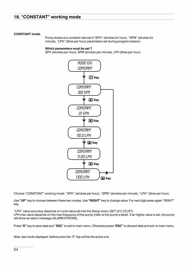
CONSTANT mode.Pump doses at a constant rate set in“SPH” (strokes for hour), “SPM” (strokes forminute), “LPH” (litres per hour) parameters set during program session.
Which parameters must be set ?SPH (strokes per hour), SPM (strokes per minute), LPH (litres per hour).
Choose “CONSTANT” working mode: “SPH” (strokes per hour), “SPM” (strokes per minute), “LPH” (litres per hour).
Use “UP” key to choose between these two modes. Use “RIGHT” key to change value. For next digit press again “RIGHT”key.
“LPH” value accuracy depends on cc/st value set into the Setup menu (SET [01] CC/ST).LPH max value depends on the max frequency of the pump (refer to the pump’s label). If an higher value is set, the pumpwill show an alarm message (ALARM STROKE).
Press “E” key to save data and “ESC” to exit to main menu. Otherwise press “ESC” to discard data and exit to main menu.
Note: last mode displayed before press the “E” key will be the active one.
mode [01]CONSTANT
CONSTANT100 spm
KeyE
CONSTANT01 sph
Key
Key
CONSTANT110.0 lph
Key
CONSTANT11.00 lph
CONSTANT1.100 lph
Key
Key
35
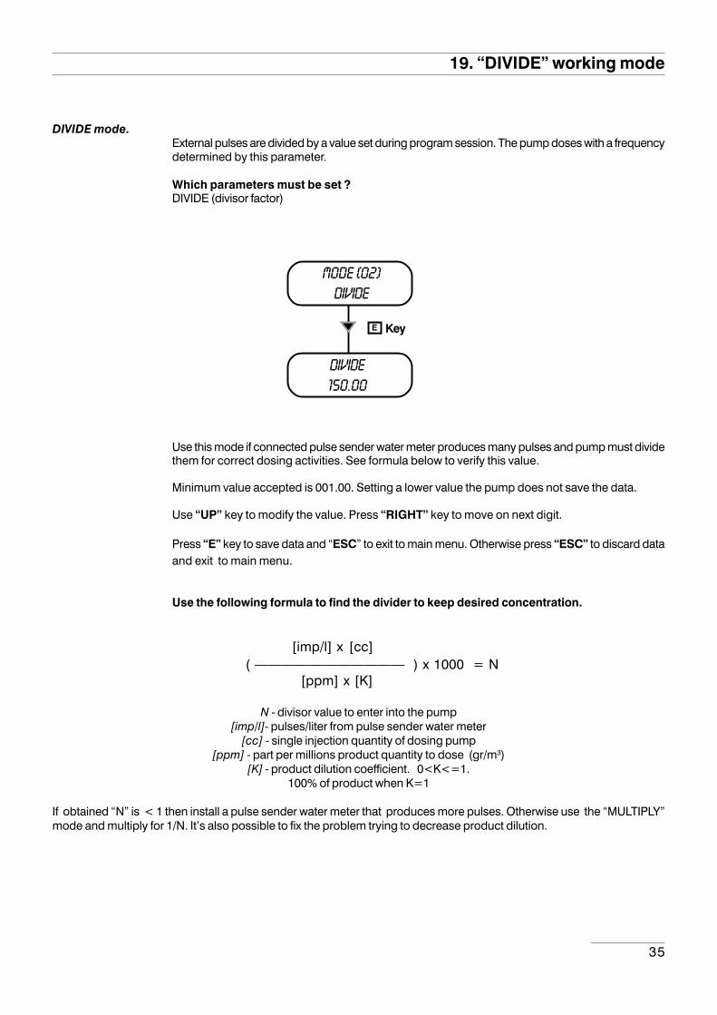
DIVIDE mode.External pulses are divided by a value set during program session. The pump doses with a frequencydetermined by this parameter.
Which parameters must be set ?DIVIDE (divisor factor)
mode [02]divide
DIVIDE150.00
KeyE
Use this mode if connected pulse sender water meter produces many pulses and pump must dividethem for correct dosing activities. See formula below to verify this value.
Minimum value accepted is 001.00. Setting a lower value the pump does not save the data.
Use “UP” key to modify the value. Press “RIGHT” key to move on next digit.
Press “E” key to save data and “ESC” to exit to main menu. Otherwise press “ESC” to discard dataand exit to main menu.
Use the following formula to find the divider to keep desired concentration.
[imp/l] x [cc] ( ——————————— ) x 1000 = N
[ppm] x [K]
N - divisor value to enter into the pump[imp/l]- pulses/liter from pulse sender water meter
[cc] - single injection quantity of dosing pump[ppm] - part per millions product quantity to dose (gr/m3)
[K] - product dilution coefficient. 0<K<=1.100% of product when K=1
If obtained “N” is < 1 then install a pulse sender water meter that produces more pulses. Otherwise use the “MULTIPLY”mode and multiply for 1/N. It’s also possible to fix the problem trying to decrease product dilution.
19. “DIVIDE” working mode
36
20. “MULTIPLY” working mode
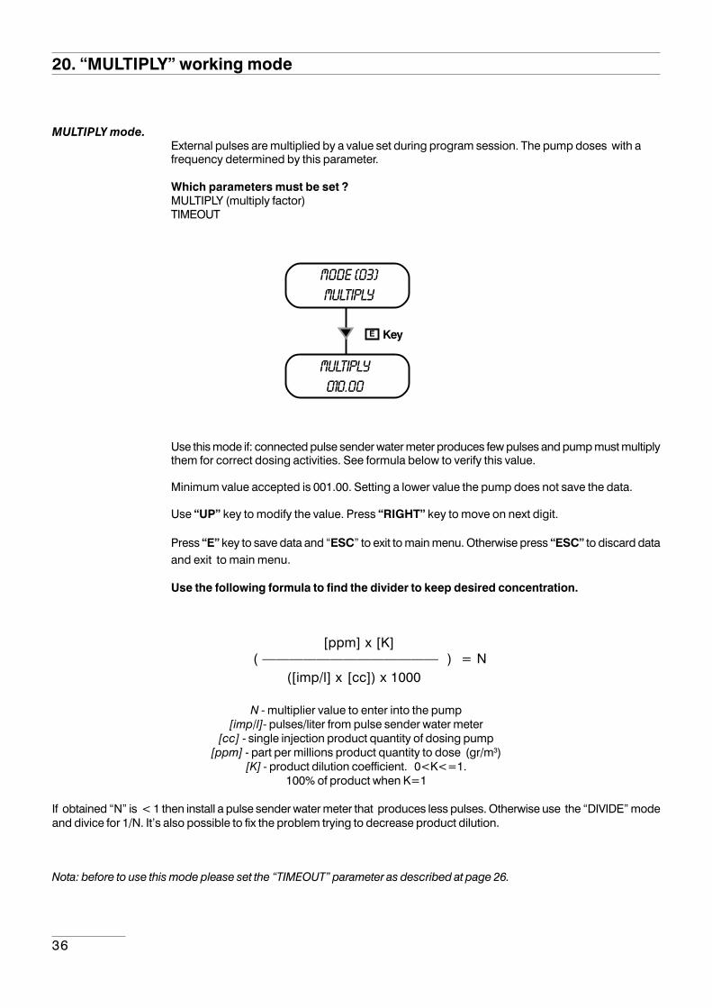
MULTIPLY mode.External pulses are multiplied by a value set during program session. The pump doses with afrequency determined by this parameter.
Which parameters must be set ?MULTIPLY (multiply factor)TIMEOUT
mode [03]multiply
multiply010.00
KeyE
Use this mode if: connected pulse sender water meter produces few pulses and pump must multiplythem for correct dosing activities. See formula below to verify this value.
Minimum value accepted is 001.00. Setting a lower value the pump does not save the data.
Use “UP” key to modify the value. Press “RIGHT” key to move on next digit.
Press “E” key to save data and “ESC” to exit to main menu. Otherwise press “ESC” to discard dataand exit to main menu.
Use the following formula to find the divider to keep desired concentration.
[ppm] x [K] ( ————————————— ) = N ([imp/l] x [cc]) x 1000
N - multiplier value to enter into the pump[imp/l]- pulses/liter from pulse sender water meter
[cc] - single injection product quantity of dosing pump[ppm] - part per millions product quantity to dose (gr/m3)
[K] - product dilution coefficient. 0<K<=1.100% of product when K=1
If obtained “N” is < 1 then install a pulse sender water meter that produces less pulses. Otherwise use the “DIVIDE” modeand divice for 1/N. It’s also possible to fix the problem trying to decrease product dilution.
Nota: before to use this mode please set the “TIMEOUT” parameter as described at page 26.
37
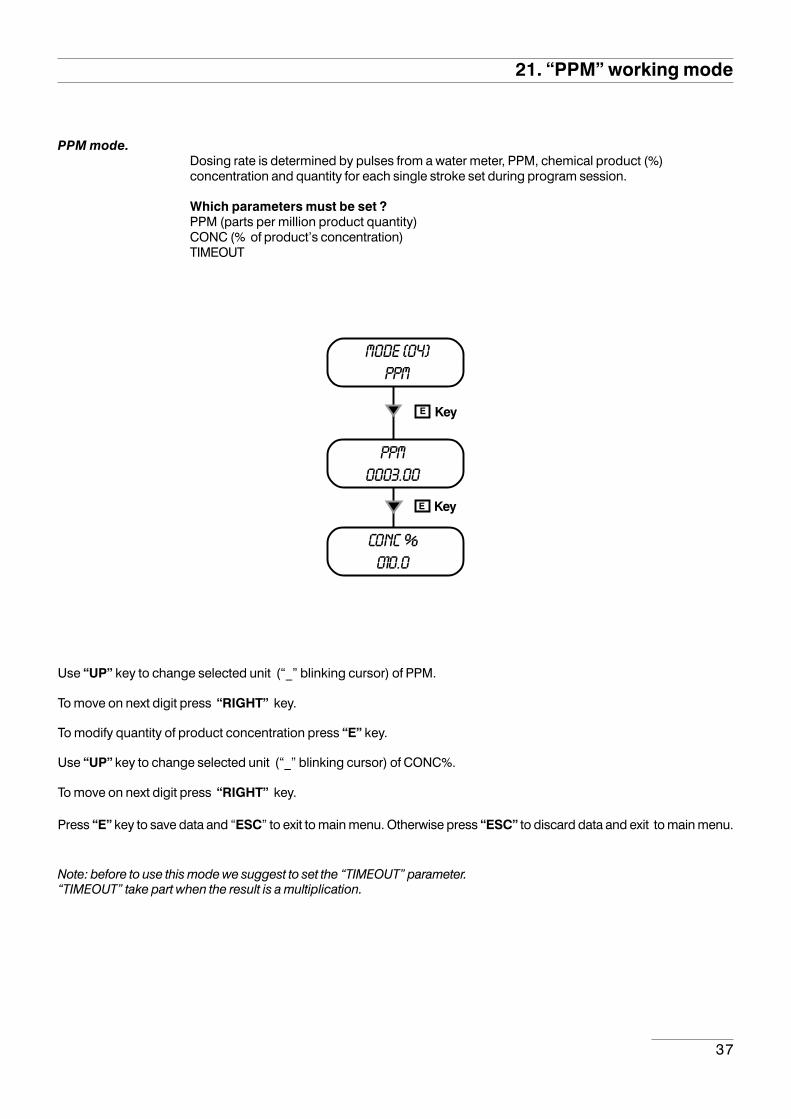
PPM mode.Dosing rate is determined by pulses from a water meter, PPM, chemical product (%)concentration and quantity for each single stroke set during program session.
Which parameters must be set ?PPM (parts per million product quantity)CONC (% of product’s concentration)TIMEOUT
Use “UP” key to change selected unit (“_” blinking cursor) of PPM.
To move on next digit press “RIGHT” key.
To modify quantity of product concentration press “E” key.
Use “UP” key to change selected unit (“_” blinking cursor) of CONC%.
To move on next digit press “RIGHT” key.
Press “E” key to save data and “ESC” to exit to main menu. Otherwise press “ESC” to discard data and exit to main menu.
Note: before to use this mode we suggest to set the “TIMEOUT” parameter.“TIMEOUT” take part when the result is a multiplication.
21. “PPM” working mode
mode [04]PPM
ppm0003.00
KeyE
conc %010.0
KeyE
38
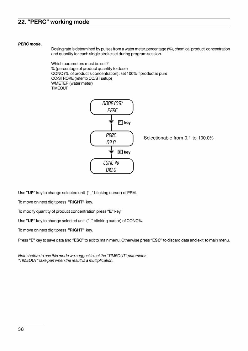
PERC mode.Dosing rate is determined by pulses from a water meter, percentage (%), chemical product concentrationand quantity for each single stroke set during program session.
Which parameters must be set ?% (percentage of product quantity to dose)CONC (% of product’s concentration): set 100% if product is pureCC/STROKE (refer to CC/ST setup)WMETER (water meter)TIMEOUT
22. “PERC” working mode
mode [05]PERC
perc03.0
keyE
conc %010.0
keyE
Selectionable from 0.1 to 100.0%
Use “UP” key to change selected unit (“_” blinking cursor) of PPM.
To move on next digit press “RIGHT” key.
To modify quantity of product concentration press “E” key.
Use “UP” key to change selected unit (“_” blinking cursor) of CONC%.
To move on next digit press “RIGHT” key.
Press “E” key to save data and “ESC” to exit to main menu. Otherwise press “ESC” to discard data and exit to main menu.
Note: before to use this mode we suggest to set the “TIMEOUT” parameter.“TIMEOUT” take part when the result is a multiplication.

39
MLQ mode.Dosing rate is determined by pulses from a water meter on the base of set MLQ (milliliters perquintal), chemical product concentration (%) and quantity for each single stroke set during programsession.
Which parameters must be set ?MLQ (product quantity in milliliters per quintal)CONC (% of product’s concentration): set 100% if product is pureCC/STROKE (refer to CC/ST setup)WMETER (water meter)TIMEOUT
23. “MLQ” working mode
mode [06]MLQ
MLQ03.00
keyE
conc %010.0
keyE
Use “UP” key to change selected unit (“_” blinking cursor) of MLQ.
To move on next digit press “RIGHT” key.
To modify quantity of product concentration press “E” key.
Use “UP” key to change selected unit (“_” blinking cursor) of CONC%.
To move on next digit press “RIGHT” key.
Press “E” key to save data and “ESC” to exit to main menu. Otherwise press “ESC” to discard data and exit to main menu.
Note: before to use this mode we suggest to set the “TIMEOUT” parameter.“TIMEOUT” take part when the result is a multiplication.
40
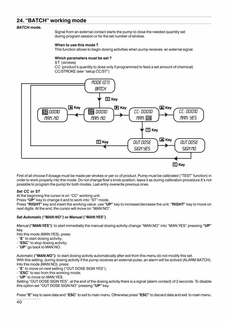
24. “BATCH” working modeBATCH mode.
Signal from an external contact starts the pump to dose the needed quantity setduring program session or for the set number of strokes.
When to use this mode ?This function allows to begin dosing activities when pump receives an external signal.
Which parameters must be set ?ST (strokes)CC (product’s quantity to dose only if programmed to feed a set amount of chemical)CC/STROKE (see “setup CC/ST”)
First of all choose if dosage must be made per strokes or per cc of product. Pump must be calibrated (“TEST” function) inorder to work properly into this mode. Do not change flow’s knob position: leave it as during calibration procedure.It’s notpossible to program the pump for both modes. Last entry overwrite previous ones.
Set CC or STAt the beginning the cursor is on “CC” working unit.Press “UP” key to change it and to work into “ST” mode.Press “RIGHT” key and insert the working value: use “UP” key to increase/decrease the unit; “RIGHT” key to move onnext digits. At the end, the cursor will move on “MAN:NO”.
Set Automatic (“MAN:NO”) or Manual (“MAN:YES”)
Manual (“MAN:YES”): to start immediatly the manual dosing activity change “MAN:NO” into “MAN:YES” pressing “UP”key.Into this mode (MAN:YES), press:- “E” to start dosing activity;- “ESC” to stop dosing activity;- “UP” go back to MAN:NO.
Automatic (“MAN:NO”): to start dosing activity automatically after exit from this menu do not modify this set.With this setting, during dosing activity if the pump receives an external pulse, an alarm will be actived (ALARM BATCH).Into this mode (MAN:NO), press:- “E” to move on next setting (“OUT DOSE SIGN YES”);- “ESC” to esc from this working mode;- “UP” to move on MAN:YES.Setting “OUT DOSE SIGN YES”, at the end of the dosing activity there is a signal (alarm contact) of 2 seconds. To disablethis option set “OUT DOSE SIGN NO” pressing “UP” key.
Press “E” key to save data and “ESC” to exit to main menu. Otherwise press “ESC” to discard data and exit to main menu.
mode [07]batch
KeyE
OUT DOSeSIGN NO
OUT DOSeSIGN YES
KeyE
Key
KeyE
KeyE
cc: 00010man: yes
Keycc: 00010man: no
Keycc: 00010man: no
st: 00010man: no
Key
41
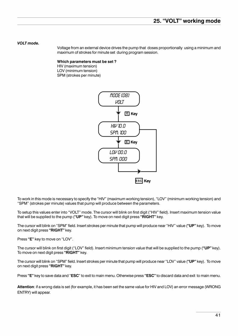
VOLT mode.Voltage from an external device drives the pump that doses proportionally using a minimum andmaximum of strokes for minute set during program session.
Which parameters must be set ?HIV (maximum tension)LOV (minimum tension)SPM (strokes per minute)
25. “VOLT” working mode
mode [08]volt
hiv 10.0spm: 100
KeyE
lov 00.0spm: 000
KeyE
KeyESC
To work in this mode is necessary to specify the “HIV” (maximum working tension), “LOV” (minimum working tension) and“SPM” (strokes per minute) values that pump will produce between the parameters.
To setup this values enter into “VOLT” mode. The cursor will blink on first digit (“HIV” field). Insert maximum tension valuethat will be supplied to the pump (“UP” key). To move on next digit press “RIGHT” key.
The cursor will blink on “SPM” field. Insert strokes per minute that pump will produce near “HIV” value (“UP” key). To moveon next digit press “RIGHT” key.
Press “E” key to move on “LOV”.
The cursor will blink on first digit (“LOV” field). Insert minimum tension value that will be supplied to the pump (“UP” key).To move on next digit press “RIGHT” key.
The cursor will blink on “SPM” field. Insert strokes per minute that pump will produce near “LOV” value (“UP” key). To moveon next digit press “RIGHT” key.
Press “E” key to save data and “ESC” to exit to main menu. Otherwise press “ESC” to discard data and exit to main menu.
Attention: if a wrong data is set (for example, it has been set the same value for HIV and LOV) an error message (WRONGENTRY) will appear.

42
26. “mA” working mode
mA mode.Current from an external device drives the pump that doses proportionally using a minimum andmaximum of strokes for minute set during program session.
Which parameters must be set ?HImA (maximum current)LOmA (minimum current)SPM (strokes per minute)
mode [09]ma
hima 10.0spm: 100
E
loma 00.0spm: 000
KeyE
KeyESC
To work in this mode is necessary to specify the “HImA” (maximum working current), “LOmA” (minimum working current)and “SPM” (strokes per minute) values that pump will produce between the parameters.
To setup this values enter into “mA” mode. The cursor will blink on first digit (“HImA” field). Insert maximum current valuethat will be supplied to the pump (“UP” key). To move on next digit press “RIGHT” key.
The cursor will blink on “SPM” field. Insert strokes per minute that pump will produce near “HImA” value (“UP” key). To moveon next digit press “RIGHT” key.
Press “E” key to move on “LOmA”.
The cursor will blink on first digit (“LOmA” field). Insert minimum current value that will be supplied to the pump (“UP” key).To move on next digit press “RIGHT” key.
The cursor will blink on “SPM” field. Insert strokes per minute that pump will produce near “LOmA” value (“UP” key). Tomove on next digit press “RIGHT” key.
Press “E” key to save data and “ESC” to exit to main menu. Otherwise press “ESC” to discard data and exit to main menu.
Attention: if a wrong data is set (for example, it has been set the same value for HIV and LOV) an error message (WRONGENTRY) will appear.
Key
43
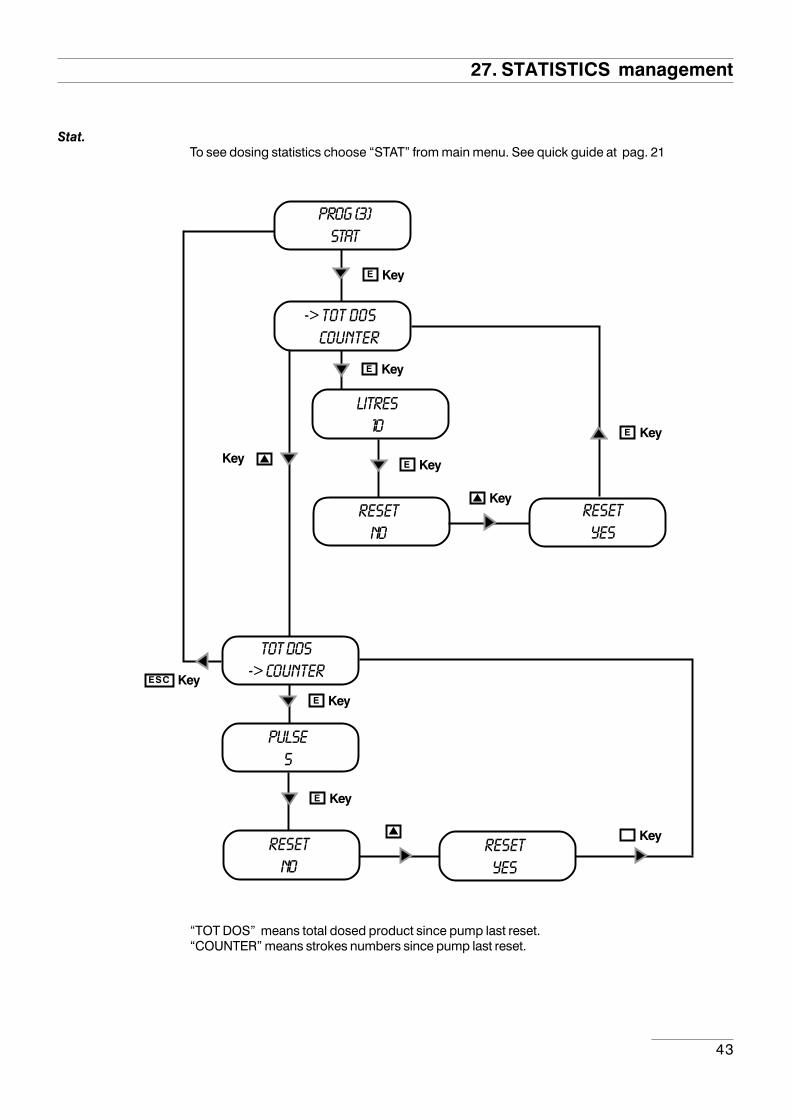
27. STATISTICS management
Stat.To see dosing statistics choose “STAT” from main menu. See quick guide at pag. 21
“TOT DOS” means total dosed product since pump last reset.“COUNTER” means strokes numbers since pump last reset.
prog [3]stat
-> tot dos counter
KeyE
litres10
KeyE
KeyE
resetno
KeyE
Key
pulse5
KeyE
resetno
resetyes
Key
KeyE
resetyes
tot dos-> counter
Key
KeyESC
44
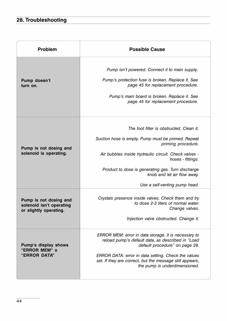
28. Troubleshooting
Problem Possible Cause
Pump doesn’tturn on.
Pump isn’t powered. Connect it to main supply.
Pump’s protection fuse is broken. Replace it. Seepage 45 for replacement procedure.
Pump’s main board is broken. Replace it. Seepage 45 for replacement procedure.
Pump is not dosing andsolenoid is operating.
The foot filter is obstructed. Clean it.
Suction hose is empty. Pump must be primed. Repeatpriming procedure.
Air bubbles inside hydraulic circuit. Check valves -hoses - fittings.
Product to dose is generating gas. Turn dischargeknob and let air flow away.
Use a self-venting pump head.
Pump is not dosing andsolenoid isn’t operatingor slightly operating.
Crystals presence inside valves. Check them and tryto dose 2-3 liters of normal water.
Change valves.
Injection valve obstructed. Change it.
Pump’s display shows“ERROR MEM” o“ERROR DATA”
ERROR MEM: error in data storage. it is necessary toreload pump’s default data, as described in “Load
default procedure” on page 28.
ERROR DATA: error in data setting. Check the valuesset. If they are correct, but the message still appears,
the pump is underdimensioned.
45
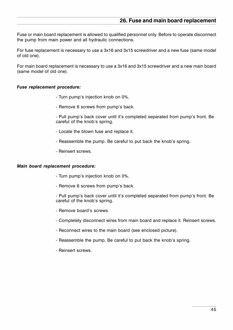
26. Fuse and main board replacement
Fuse or main board replacement is allowed to qualified personnel only. Before to operate disconnectthe pump from main power and all hydraulic connections.
For fuse replacement is necessary to use a 3x16 and 3x15 screwdriver and a new fuse (same modelof old one).
For main board replacement is necessary to use a 3x16 and 3x15 screwdriver and a new main board(same model of old one).
Fuse replacement procedure:
- Turn pump’s injection knob on 0%.
- Remove 6 screws from pump’s back.
- Pull pump’s back cover until it’s completed separated from pump’s front. Becareful of the knob’s spring.
- Locate the blown fuse and replace it.
- Reassemble the pump. Be careful to put back the knob’s spring.
- Reinsert screws.
Main board replacement procedure:
- Turn pump’s injection knob on 0%.
- Remove 6 screws from pump’s back.
- Pull pump’s back cover until it’s completed separated from pump’s front. Becareful of the knob’s spring.
- Remove board’s screws.
- Completely disconnect wires from main board and replace it. Reinsert screws.
- Reconnect wires to the main board (see enclosed picture).
- Reassemble the pump. Be careful to put back the knob’s spring.
- Reinsert screws.

46
27. Main Board
TRANSFORMER
FUSE+ Level
GND
N.C.
C.
N.O.
-+
+ Stand-by
SEFL
- Input
+ Input
Solenoid
Powersupply
47
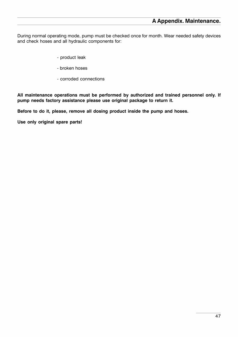
A Appendix. Maintenance.
During normal operating mode, pump must be checked once for month. Wear needed safety devicesand check hoses and all hydraulic components for:
- product leak
- broken hoses
- corroded connections
All maintenance operations must be performed by authorized and trained personnel only. Ifpump needs factory assistance please use original package to return it.
Before to do it, please, remove all dosing product inside the pump and hoses.
Use only original spare parts!
48
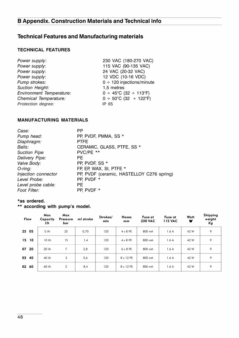
B Appendix. Construction Materials and Technical info
Technical Features and Manufacturing materials
TECHNICAL FEATURES
Power supply: 230 VAC (180-270 VAC)Power supply: 115 VAC (90-135 VAC)Power supply: 24 VAC (20-32 VAC)Power supply: 12 VDC (10-16 VDC)Pump strokes: 0 ÷ 120 injections/minuteSuction Height: 1,5 metresEnvironment Temperature: 0 ÷ 45°C (32 ÷ 113°F)Chemical Temperature: 0 ÷ 50°C (32 ÷ 122°F)Protection degree: IP 65
MANUFACTURING MATERIALS
Case: PPPump head: PP, PVDF, PMMA, SS *Diaphragm: PTFEBalls: CERAMIC, GLASS, PTFE, SS *Suction Pipe PVC/PE **Delivery Pipe: PEValve Body: PP, PVDF, SS *O-ring: FP, EP, WAX, SI, PTFE *Injection connector PP, PVDF (ceramic, HASTELLOY C276 spring)Level Probe: PP, PVDF *Level probe cable: PEFoot Filter: PP, PVDF *
*as ordered.** according with pump’s model.
FlowMax
Capacityl /h
MaxPressure
barml stroke
Strokes/min
Hosesmm
Fuse at230 VAC
Fuse at115 VAC
WattWWWW
Shippingweight
Kg
25 05 5 l/h 25 0,70 120 4 x 8 PE 800 mA 1.6 A 42 W 9
15 10 10 l/h 15 1,4 120 4 x 8 PE 800 mA 1.6 A 42 W 9
07 20 20 l/h 7 2,8 120 6 x 8 PE 800 mA 1.6 A 42 W 9
03 40 40 l/h 3 5,6 120 8 x 12 PE 800 mA 1.6 A 42 W 9
02 60 60 l/h 2 8,4 120 8 x 12 PE 800 mA 1.6 A 42 W 9
49
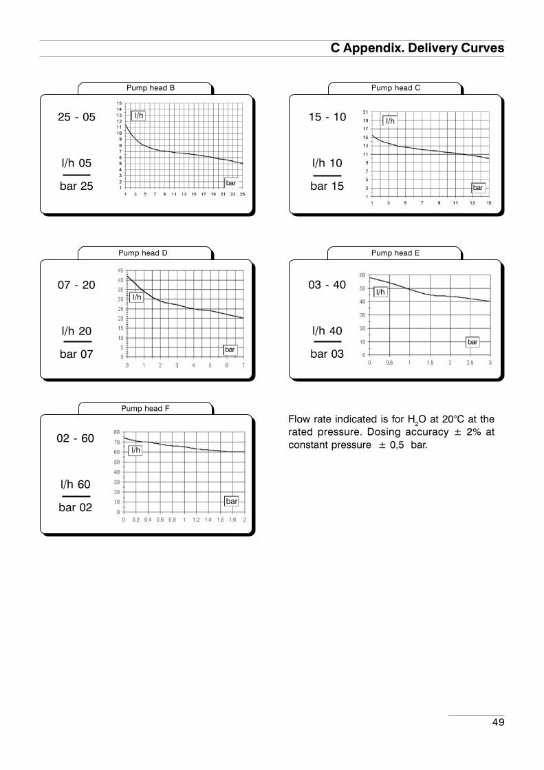
C Appendix. Delivery Curves
07 - 20
l/h 20
bar 07
03 - 40
l/h 40
bar 03
l/hl/h
barbar
02 - 60
l/h 60
bar 02
l/h
bar
25 - 05
l/h 05
bar 25
15 - 10
l/h 10
bar 15
l/hl/h
barbar
Flow rate indicated is for H2O at 20°C at therated pressure. Dosing accuracy ± 2% atconstant pressure ± 0,5 bar.
Pump head EPump head D
Pump head F
Pump head CPump head B
50
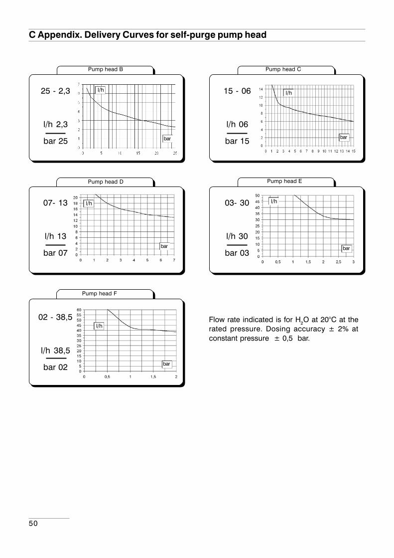
C Appendix. Delivery Curves for self-purge pump head
07- 13
l/h 13
bar 07
03- 30
l/h 30
bar 03
15 - 06
l/h 06
bar 15
Flow rate indicated is for H2O at 20°C at therated pressure. Dosing accuracy ± 2% atconstant pressure ± 0,5 bar.
25 - 2,3
l/h 2,3
bar 25
l/h
bar
l/h
bar
l/h
bar
l/h
bar
02 - 38,5
l/h 38,5
bar 02
l/h
bar
Pump head EPump head D
Pump head F
Pump head CPump head B
51
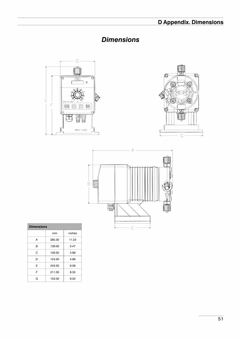
D Appendix. Dimensions
Dimensions
Dimensions
mm inches
A 285.30 11.23
B 139.00 5.47
C 126.50 4.98
D 124.00 4.88
E 243.50 9.58
F 211.00 8.30
G 153.00 6.02
52
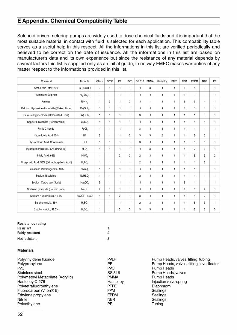
Solenoid driven metering pumps are widely used to dose chemical fluids and it is important that themost suitable material in contact with fluid is selected for each application. This compatibility tableserves as a useful help in this respect. All the informations in this list are verified periodically andbelieved to be correct on the date of issuance. All the informations in this list are based onmanufacturer's data and its own experience but since the resistance of any material depends byseveral factors this list is supplied only as an initial guide, in no way EMEC makes warranties of anymatter respect to the informations provided in this list.
Resistance ratingResistant 1Fairly resistant 2
Not resistant 3
Materials
Polyvinyldene fluoride PVDF Pump Heads, valves, fitting, tubingPolypropylene PP Pump Heads, valves, fitting, level floaterPVC PVC Pump HeadsStainless steel SS 316 Pump Heads, valvesPolymethyl Metacrilate (Acrylic) PMMA Pump HeadsHastelloy C-276 Hastelloy Injection valve springPolytetrafluoroethylene PTFE DiaphragmFluorocarbon (Viton® B) FPM SealingsEthylene propylene EPDM SealingsNitrile NBR SealingsPolyethylene PE Tubing
E Appendix. Chemical Compatibility Table
Chemical Formula Glass PVDF PP PVC SS 316 PMMA Hastelloy PTFE FPM EPDM NBR PE
Acetic Acid, Max 75% CH3COOH 2 1 1 1 1 3 1 1 3 1 3 1
Aluminium Sulphate Al2(SO4)3 1 1 1 1 1 1 1 1 1 1 1 1
Amines R-NH2 1 2 1 3 1 - 1 1 3 2 4 1
Calcium Hydroxide (Lime Milk)(Slaked Lime) Ca(OH)2 1 1 1 1 1 1 1 1 1 1 1 1
Calcium Hypochlorite (Chlorinated Lime) Ca(OCl)2 1 1 1 1 3 1 1 1 1 1 3 1
Copper-II-Sulphate (Roman Vitriol) CuSO4 1 1 1 1 1 1 1 1 1 1 1 1
Ferric Chloride FeCl3 1 1 1 1 3 1 1 1 1 1 1 1
Hydrofluoric Acid 40% HF 3 1 1 2 3 3 2 1 1 3 3 1
Hydrochloric Acid, Concentrate HCl 1 1 1 1 3 1 1 1 1 3 3 1
Hydrogen Peroxide, 30% (Perydrol) H2O2 1 1 1 1 1 3 1 1 1 2 3 1
Nitric Acid, 65% HNO3 1 1 2 3 2 3 1 1 1 3 3 2
Phosphoric Acid, 50% (Orthophosphoric Acid) H3PO4 1 1 1 1 2 1 1 1 1 1 3 1
Potassium Permanganate, 10% KMnO4 1 1 1 1 1 1 1 1 1 1 3 1
Sodium Bisulphite NaHSO3 1 1 1 1 2 1 1 1 1 1 1 1
Sodium Carbonate (Soda) Na2CO3 2 1 1 1 1 1 1 1 2 1 1 1
Sodium Hydroxide (Caustic Soda) NaOH 2 1 1 1 1 1 1 1 2 1 2 1
Sodium Hypochlorite, 12.5% NaOCl + NaCl 1 1 2 1 3 1 1 1 1 1 2 1
Sulphuric Acid, 85% H2SO4 1 1 1 1 2 3 1 1 1 3 3 1
Sulphuric Acid, 98.5% H2SO4 1 1 3 3 3 3 1 1 1 3 3 3
53
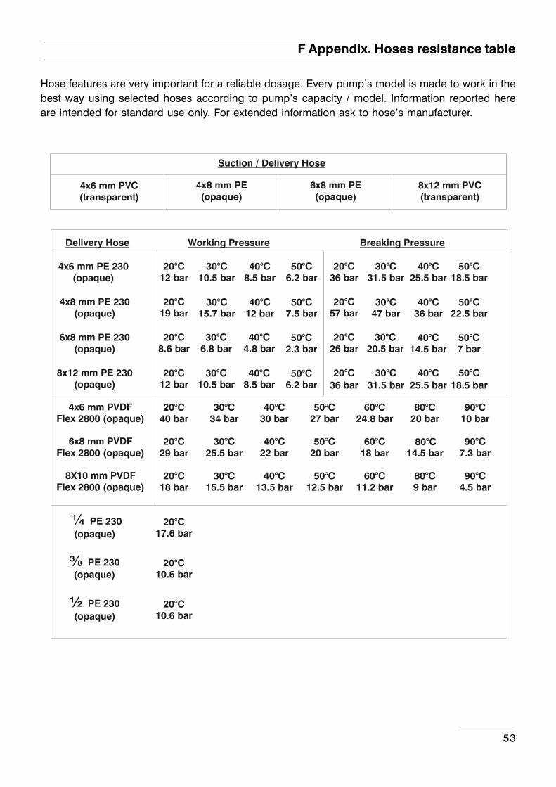
F Appendix. Hoses resistance table
Hose features are very important for a reliable dosage. Every pump’s model is made to work in thebest way using selected hoses according to pump’s capacity / model. Information reported hereare intended for standard use only. For extended information ask to hose’s manufacturer.
54
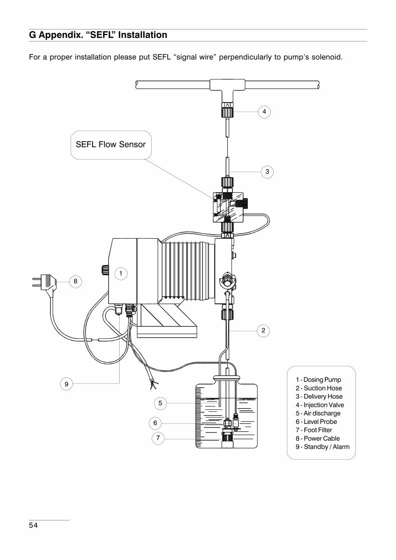
G Appendix. “SEFL” Installation
SEFL Flow Sensor
1 - Dosing Pump2 - Suction Hose3 - Delivery Hose4 - Injection Valve5 - Air discharge6 - Level Probe7 - Foot Filter8 - Power Cable9 - Standby / Alarm
1
5
6
7
8
9
2
3
4
For a proper installation please put SEFL “signal wire” perpendicularly to pump’s solenoid.

55
H Appendix. Summary
Summary
1. Introduction ......................................................................................................................................... 32. Unpacking ........................................................................................................................................... 43. Pump’s description ............................................................................................................................. 54. Before to Install warnings .................................................................................................................... 65. Installation Draw .................................................................................................................................. 76. Hydraulic Installation ........................................................................................................................... 87. Electrical Installation .......................................................................................................................... 128. Basic Settings .................................................................................................................................... 149. Priming .............................................................................................................................................. 1610. Pump’s functions summary ............................................................................................................ 1710. Pump’s functions summary- ALARMS ............................................................................................ 1812. Quick Guide - Main Menu (Prog [2] Setup) ................................................................................. 2015. Setup ............................................................................................................................................... 2216. “Load default” and “Reset Password” procedure ....................................................................... 3017. Working procedure setup .............................................................................................................. 3118. “CONSTANT” working mode ........................................................................................................ 3419. “DIVIDE” working mode ................................................................................................................ 3520. “MULTIPLY” working mode ............................................................................................................ 3621. “PPM” working mode ..................................................................................................................... 3722. “PERC” working mode ................................................................................................................... 3823. “MLQ” working mode .................................................................................................................... 3924. “BATCH” working mode ................................................................................................................ 4025. “VOLT” working mode ................................................................................................................... 4126. “mA” working mode ....................................................................................................................... 4227. STATISTICS management ............................................................................................................. 4328. Troubleshooting ............................................................................................................................... 4426. Fuse and main board replacement ................................................................................................ 4527. Main Board ...................................................................................................................................... 46A Appendix. Maintenance. ................................................................................................................... 47B Appendix. Construction Materials and Technical info ...................................................................... 48Technical Features and Manufacturing materials ................................................................................ 48C Appendix. Delivery Curves ............................................................................................................... 49C Appendix. Delivery Curves for self-purge pump head .................................................................... 50D Appendix. Dimensions ...................................................................................................................... 51E Appendix. Chemical Compatibility Table .......................................................................................... 52 F Appendix. Hoses resistance table .................................................................................................... 53G Appendix. “SEFL” Installation ............................................................................................................ 54H Appendix. Summary ......................................................................................................................... 55

56
When dismantling a pump please separate material types and send them according to local recycling disposal requirements.We appreciate your efforts in supporting your local Recycle Environmental Program.
Working together we’ll form an active union to assure the world’s invaluable resources are conserved.