operating, maintaining & installing your light commercial...
TRANSCRIPT

REVISED April 14, 2008
OOPPEERRAATTIINNGG,, MMAAIINNTTAAIINNIINNGG && IINNSSTTAALLLLIINNGG YYOOUURR LLIIGGHHTT
CCOOMMMMEERRCCIIAALL HHEEAATT RREECCOOVVEERRYY VVEENNTTIILLAATTOORR
* LEAVE THIS DOCUMENT WITH THE BUILDING OWNER
Specifications, dimensions and ratings may change without notice
as a result of ongoing product development and improvements.
NU305, NU500, NU600
(Type 362317, & 423023)
P.O. Box 2758
Windsor, Nova Scotia, B0N 2T0
Ph. 902-798-2261 Fax: 902-798-2557
www.nu-airventilation.com
E-mail: [email protected]

REVISED April 14, 2008
TABLE OF CONTENTS
1 HOW THE NU-AIR SYSTEM WORKS ...........................................................................................................4
2 FEATURES & OPERATION ...........................................................................................................................4
3 CONTROLS.......................................................................................................................................................6
3.1 Standard Dehumidistat (Part#: DSTAT-1) &......................................................................... 6
Internal Dehumidistat (Part#: DSTATK-01) ...................................................................................... 6
3.2 2-Speed Control (Part #: 2X605A) .......................................................................................... 6
3.3 Windsor Dehumidistat Control (Part#: WIN-1)..................................................................... 7
3.4 Windsor 20 Minute High Speed Timer (Part#: WIN-20) ...................................................... 7
3.5 Arctic Defrost Mode .................................................................................................................. 7
4 INSTALLATION INSTRUCTIONS.................................................................................................................7
4.1 Installer’s Responsibilities ........................................................................................................ 7
4.3 Installation Basics...................................................................................................................... 8 4.3.1 Standard Issue Items .........................................................................................................................8 4.3.2 Other Basic Needs.............................................................................................................................8
4.4 Ductwork.................................................................................................................................... 8 4.4.1 Ducting from the Weather Hoods .....................................................................................................9
4.5 Weather Hoods .......................................................................................................................... 9 4.5.1 Locating the Weather Hoods (Commercial) .....................................................................................9 4.5.2 Locating the Weather Hoods (Residential) .......................................................................................9
4.6 Port Configurations................................................................................................................. 10
4.7 Mounting & Noise Control (NU305, NU500) ........................................................................ 11 4.7.1 Mounting & Noise Control NU600 ..............................................................................................11
4.8 Drain Connections ................................................................................................................... 12
5 CONNECTING TO OTHER EQUIPMENT..................................................................................................12
6 EXTERNAL CONNECTIONS .......................................................................................................................13
6.1 Furnace Interlock .................................................................................................................... 13
6.2 Windsor Control (Part#: WIN-1)........................................................................................... 13
6.3 Standard Dehumidistat (Part#: DSTAT-1) ........................................................................... 14
6.4 Internal Dehumidistat (Part#: DSTATK01) ......................................................................... 14 6.4.1 Field Installed – Models NU305, NU500 .......................................................................................14 6.4.2 Factory Installed – Models NU600 .................................................................................................14
6.5 Windsor 20 Minute High Speed Timer (Part #: WIN-20) ................................................... 14
6.6 Spring Wound Timers............................................................................................................. 14
6.7 Remote On/Off Switching....................................................................................................... 15
7 BALANCING THE SYSTEM .........................................................................................................................15
8 MAINTENANCE.............................................................................................................................................17
8.1 Filters ........................................................................................................................................ 17

REVISED April 14, 2008
8.2 Fans........................................................................................................................................... 17
8.3 Condensate Drain .................................................................................................................... 17
8.4 Core........................................................................................................................................... 17
8.5 Exterior Hoods......................................................................................................................... 18
8.6 Diffusers and Ductwork .......................................................................................................... 18
9 ANNUAL SERVICING...................................................................................................................................18
10 TROUBLE SHOOTING..................................................................................................................................19
10.1 Electronic Self-Resetting Fuse:............................................................................................... 20
10.2 Troubleshooting using the PCB light: ................................................................................... 20
11 ELECTRICAL SCHEMATICS.......................................................................................................................21
11.1 NU305, NU500 and NU600 Fan Shut Down Defrost ............................................................ 21
11.2 NU305, NU500 and NU600 Damper Defrost......................................................................... 22
12 WARRANTY ....................................................................................................................................................23

REVISED April 14, 2008 Page 4 of 23
1 HOW THE NU-AIR SYSTEM WORKS
This heat recovery ventilator (HRV) provides fresh air to a conditioned space
while exhausting an equal amount of stale air. Heat energy is transferred from one
air stream to the other within a non-contact cross flow heat exchanger.
A. Two forward curve blowers work to bring fresh air into the space and exhaust
an equal amount of stale air.
B. Incoming fresh air is filtered before flowing through the heat exchange core.
C. Stale, humid air flows through the cross-flow heat exchanger and transfers the
heat to the incoming fresh air.
D. Warm fresh air is distributed through an independent ductwork system or an
existing air distribution system.
2 FEATURES & OPERATION
NU305, NU500, and NU600 light commercial HRV
models use microprocessor based control technology.
The standard control configurations of these HRV’s
consist of two speed settings selectable from a remote
control. Connection between the HRV and control is
achieved through low voltage wiring.
Features include:
• Powerful transformer – up to six (6) WIN-20 Timers can be connected in
parallel.
• Field selectable defrost cycle for northern applications.
• Self-resetting fuse to protect the board against mis-wiring.
• Variable low speed control – HRV low speed can be adjusted between a
minimum of 40% and a maximum of 70% of high speed. See below
explanation.
• Optional setting for 220V/50Hz geographic areas.
REVISED April 14, 2008 Page 5 of 23
The following sections outline the features and explain the PC board in greater
detail. Settings for speed control, defrost, electrical service and fan/motor type
are factory set for normal operation and do not require changing.
A qualified technician must do any service work done within the electrical panel of
the HRV.
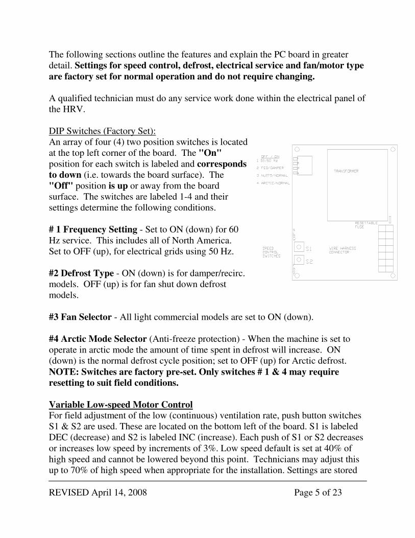
DIP Switches (Factory Set):
An array of four (4) two position switches is located
at the top left corner of the board. The "On"
position for each switch is labeled and corresponds
to down (i.e. towards the board surface). The
"Off" position is up or away from the board
surface. The switches are labeled 1-4 and their
settings determine the following conditions.
# 1 Frequency Setting - Set to ON (down) for 60
Hz service. This includes all of North America.
Set to OFF (up), for electrical grids using 50 Hz.
#2 Defrost Type - ON (down) is for damper/recirc.
models. OFF (up) is for fan shut down defrost
models.
#3 Fan Selector - All light commercial models are set to ON (down).
#4 Arctic Mode Selector (Anti-freeze protection) - When the machine is set to
operate in arctic mode the amount of time spent in defrost will increase. ON
(down) is the normal defrost cycle position; set to OFF (up) for Arctic defrost.
NOTE: Switches are factory pre-set. Only switches # 1 & 4 may require
resetting to suit field conditions.
Variable Low-speed Motor Control For field adjustment of the low (continuous) ventilation rate, push button switches
S1 & S2 are used. These are located on the bottom left of the board. S1 is labeled
DEC (decrease) and S2 is labeled INC (increase). Each push of S1 or S2 decreases
or increases low speed by increments of 3%. Low speed default is set at 40% of
high speed and cannot be lowered beyond this point. Technicians may adjust this
up to 70% of high speed when appropriate for the installation. Settings are stored

REVISED April 14, 2008 Page 6 of 23
in the board’s memory, eliminating the need to reset the speed after a power
failure..
Defrost Cycles:
Fan Shutdown Defrost – On FSD machines, the temperature sensor is located in
the fresh air stream before the core. When this air is measured to be below
freezing, a timed defrost cycle is initiated. The fresh air fan motor is stopped for 4
minutes (both normal and arctic modes). The exhaust fan motor continues to
operate, drawing warm air from the building through the core. After 4 minutes, the
fresh air fan motor is started again and runs for 20 (normal mode) or 12 (arctic
mode) minutes. This cycle is repeated until the temperature of the outdoor air
stream is measured to be above freezing.
Damper Defrost – On dampered models, the temperature sensor is located in the
fresh air stream before the core. When the outdoor air temperature is measured to
be below freezing, a timed defrost cycle is initiated. The machine runs normally for
36 (normal mode) or 20 (arctic mode) minutes and then shuts off the fresh air by
closing a damper for 4 (normal mode) or 5 (arctic mode) minutes. This timed cycle
repeats until the temperature of the outdoor air is measured to be above 0 C. Note:
When the machine has power but is not turned on, the damper automatically closes
off the fresh air port to prevent unwanted drafts while the machine is not in
operation.
3 CONTROLS This system is designed to operate on a low speed for continuous ventilation with
intermittent high speed for moisture or air quality control. Various means of
controlling the system are described below.
3.1 Standard Dehumidistat (Part#: DSTAT-1) &
Internal Dehumidistat (Part#: DSTATK-01) The dehumidistat will switch the HRV to high speed when the relative humidity of
the air around it exceeds its set point. When the humidity falls below the set point,
the machine drops out of high speed.
3.2 2-Speed Control (Part #: 2X605A)
The Standard Commercial Control, 2X605A, allows the operator the ability to
choose Hi/Low/Off from a conveniently located switch.

REVISED April 14, 2008 Page 7 of 23
3.3 Windsor Dehumidistat Control (Part#: WIN-1) The Windsor Control incorporates a 3-position switch from which the operator can
select three operating modes.
1. OFF - disables all functions.
2. STANDBY – HRV operates intermittently in high speed ventilation on
demand from the dehumidistat, timers, or other remote control. HRV
returns to STANDBY (auto – off) when remote is satisfied.
3. CONTINUOUS - continuous low speed ventilation. HRV cycles to high
speed on demand from the dehumidistat, timers, or other remote sensors.
4. HIGH SPEED VENTILATION
From the 2-position switch the HRV (ERV) can be locked into high speed
STANDARD – Normal High/Low operation
CONSTANT – Locks high speed
3.4 Windsor 20 Minute High Speed Timer (Part#: WIN-20) Install in bathrooms, kitchens, workstations or other locations where high-speed
ventilation control is needed. The machine will run at high speed for twenty (20)
minutes and then return to its normal operating condition.
3.5 Arctic Defrost Mode A field selectable Arctic Defrost Mode is available on all models and can be used
for temperatures below -20 0C (-4 F) for fan shutdown defrost models and areas
with temperatures reaching below -30 0C (-22
0F) for damper defrost models.
Consult Nu-Air Ventilation Systems Inc. or your nearest wholesaler for more
information.
4 INSTALLATION INSTRUCTIONS
4.1 Installer’s Responsibilities
Installers are responsible for the performance of the ventilation system and for
ensuring that all codes and standards are met.
• Do not mount the fresh air supply near a source of contaminated air such as
automotive exhaust, gas or propane exhaust or oil tanks.
• Combustion appliances such as furnaces and hot water heaters must not draw
combustion air directly from an HRV.

REVISED April 14, 2008 Page 8 of 23
4.3 Installation Basics
Before installing a Nu-Air Light Commercial HRV for the first time, please read
these instructions.
4.3.1 Standard Issue Items
The HRV comes equipped with:
� Filters
� Anti-vibration Springs, chain & hanging brackets (NU600)
� Heat Recovery Core
� Drain Kit
� Anti-Vibration straps (NU305, NU500)
4.3.2 Other Basic Needs
� Control Package: Standard d-stat, WIN-1, timers or other 24V controls
� Galvanized Duct
� Flexible Duct Connector
� Outside Hoods (2)
� Duct Fittings
� Duct Sealer or Tape
� Screws
� Diffusers
� Duct Hanger
� Balancing dampers
� Air flow measuring device for balancing
4.4 Ductwork
Duct runs should be straight with minimum bends and elbows. Joints should be
tight fitting and sealed with high velocity, fiber reinforced duct sealant or good
quality duct tape.
RECOMMENDATION: An engineer or other qualified person should design the
duct system
Ducting must be supported according to the designers’ specified hanger system and
intervals.
REVISED April 14, 2008 Page 9 of 23
4.4.1 Ducting from the Weather Hoods
Between the weather hoods and the HRV it is recommended to use rigid
rectangular ducting equal to or larger than the collar size of the machine. These
ducts should be wrapped with an insulating duct wrap. The minimum RSI value of
insulation should equal that of the local building codes.
4.5 Weather Hoods
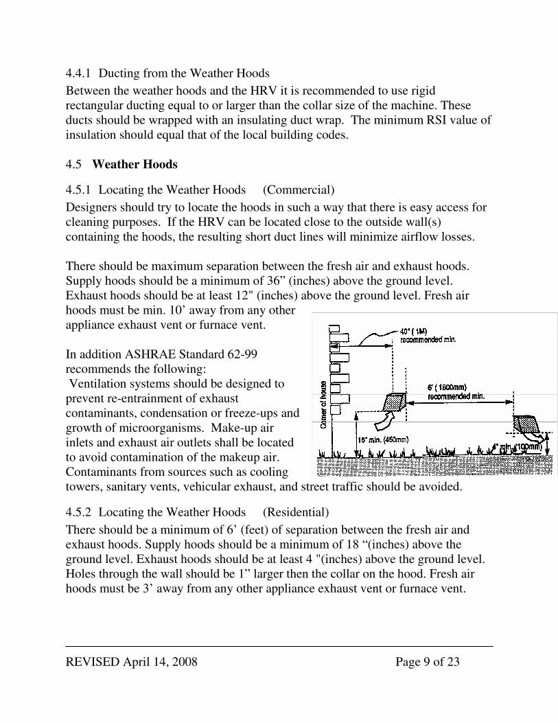
4.5.1 Locating the Weather Hoods (Commercial)
Designers should try to locate the hoods in such a way that there is easy access for
cleaning purposes. If the HRV can be located close to the outside wall(s)
containing the hoods, the resulting short duct lines will minimize airflow losses.
There should be maximum separation between the fresh air and exhaust hoods.
Supply hoods should be a minimum of 36” (inches) above the ground level.
Exhaust hoods should be at least 12" (inches) above the ground level. Fresh air
hoods must be min. 10’ away from any other
appliance exhaust vent or furnace vent.
In addition ASHRAE Standard 62-99
recommends the following:
Ventilation systems should be designed to
prevent re-entrainment of exhaust
contaminants, condensation or freeze-ups and
growth of microorganisms. Make-up air
inlets and exhaust air outlets shall be located
to avoid contamination of the makeup air.
Contaminants from sources such as cooling
towers, sanitary vents, vehicular exhaust, and street traffic should be avoided.
4.5.2 Locating the Weather Hoods (Residential)
There should be a minimum of 6’ (feet) of separation between the fresh air and
exhaust hoods. Supply hoods should be a minimum of 18 “(inches) above the
ground level. Exhaust hoods should be at least 4 "(inches) above the ground level.
Holes through the wall should be 1” larger then the collar on the hood. Fresh air
hoods must be 3’ away from any other appliance exhaust vent or furnace vent.

REVISED April 14, 2008 Page 10 of 23
4.6 Port Configurations
1 - FROM OUTSIDE 2 - TO SPACE 3 - FROM SPACE 4 - TO OUTSIDE
1 & 4 Insulated 2 & 3 Non-Insulated
Collar Sizes (inches)
NU305 8 DIA
NU500 10X6
NU600 14X8
NU305, NU500
NU600

REVISED April 14, 2008 Page 11 of 23
4.7 Mounting & Noise Control (NU305, NU500)
For maximum efficiency, the HRV should be installed in a heated area. The HRV
is designed to be hung from the ceiling by way of the anti-vibration straps
supplied. Attach rubberized anti-vibration straps with machine screws provided to
the threaded brass insert in the top corners of the cabinet. Avoid hanging the HRV
directly below a bedroom or other quiet area.
4.7.1 Mounting & Noise Control NU600
The HRV is designed to be hung from the ceiling by way of the
anti-vibration springs and chain supplied. You will also need
bolt cutters or snips and self-tapping screws. The following
items are included with the HRV:
• Galvanized suspension bracket (4)
• #10-24 x 1/2" machine screw, socket drive {Robertson}
(16)
• Suspension Springs (4)
• Double loop suspension chain (20')
1. Securely fasten the bracket to the HRV with the
machine screws supplied. (A)
2. Cut the suspension chain into four equal lengths (5' max)
3. Use a self-tapping screw to fasten the first complete link of chain to the pre-
drilled hole in the bracket. (B)
4. Hook the chain into the grab slot of the bracket. Note that the tension of the
chain must pull toward the middle of the bracket. Use the appropriate slot for
this effect. ( C )
5. Attach the free end of the chain to a structurally sound member overhead. This
will vary from site to site.
6. Form a 5" loop in the chain and hook the vibration isolation spring between the
slack. (D)
7. IMPORTANT: A. Do not rely on the spring to hold up the HRV without
chain back up. B. Flexible duct connector (PRO flex or other) should be used at
all four collars of the HRV to isolate vibration.

REVISED April 14, 2008 Page 12 of 23
4.8 Drain Connections
Access to a drain is required to handle the HRV condensate. Care should be taken to
run the condensate tube where it will not freeze.
For best results, Nu-Air recommends the following steps be followed when installing
drain kits.
1. Apply the O-ring supplied to the flange of each drain spout. (A)
2. Insert the drain spouts through the holes in the drain pan. (B)
3. Use the speed nut to tightly secure the drain spout.
4. Cut two lengths of drain hose long enough to avoid kinking. (E)
5. Attach the hose to the drain spout by sliding it over the spout until it is tight to the
bottom of the speed nut. Repeat for the
other side.
6. Secure the hose to the spout with the plastic
tie wraps. (D)
7. Install the tee fitting as shown in the drawing
below. (F)
8. Attach the free end of the hose to the left
fitting. Repeat for the other side.
9. Use the remaining hose to form a "P" trap
and terminate at the top of the tee.
10. Pour water into the drain assembly to form
an air seal. This prevents gasses from being
drawn into the HRV.
5 CONNECTING TO OTHER EQUIPMENT In general the HRV is not intended to be connected to other equipment or
appliances. Connection with a forced air furnace or air handler is common practice
but additional controls must be in place.
If the HRV is used upstream of an air handler or similar equipment (e.g. fresh air
into economizer section), the start up sequence must be HRV first followed by
the air handler. If the air handler is started first, the HRV's fresh air fan will
rotate backward and the motor may not be able to overcome the extra load, causing
an over amp situation.

REVISED April 14, 2008 Page 13 of 23
6 EXTERNAL CONNECTIONS
For electrical hook-up, the HRV should be
connected to its own circuit using electrical wire
and conduit in accordance with code requirements.
These Machines are equipped for remote controls.
Options include humidity sensing,
off/on/intermittent-on switching and high speed for
twenty minutes. You can also interlock the
furnace blower to the HRV.
6.1 Furnace Interlock To interlock the furnace blower with the HRV, supply 24 V in and
out from the furnace controls R and G lines to HRV terminals
labeled FURNACE INTERLOCK. 24 V supply ONLY. Furnace
interlock engages any time the machine is running (high or low speed) but
disengages during a defrost cycle.
NOTE - For a furnace connected to a cooling system: When using the built-in furnace interlock
relay on the HRV in conjunction with certain older
mercury bulb thermostats, energizing the R and G
terminals will also cause 24 volts to be sent through
the Y terminal which will initiate the outdoor
condenser. If this is the case, there are two possible
solutions. Either upgrade the thermostat to a digital
type which does not have Y connected to G internally,
or install the isolation relay as shown in the wiring
diagram.
6.2 Windsor Control (Part#: WIN-1)
Enables remote switching of continuous low speed ("||" CONT), all off (0 OFF) or
intermittent high speed only ("|" INT) as well as automatic humidity control. Lead
wires from the control are colour coded as follows. Black/HUM, green/INT,
HUM
INT"|"
CONT"||" 24 V
COM COM
SWITCH
LED
IN (R) OUT (G)
FURNACE INTERLOCK

REVISED April 14, 2008 Page 14 of 23
yellow/CONT, red/24V COM. Remove factory installed jumper wire at CONT
and 24 V COM. Four-conductor wire is needed.
6.3 Standard Dehumidistat (Part#: DSTAT-1)
Connection may be made at points "HUM" & "24 V COM" to automatically
control humidity. For continuous operation (low/high) use the factory installed
jumper wire between CONT"||" & COM. For intermittent operation (off/high)
reposition the jumper wire between INT "|" and COM. Two-conductor wire is
needed.
6.4 Internal Dehumidistat (Part#: DSTATK01)
6.4.1 Field Installed – Models NU305, NU500
These HRV's are pre-wired for internal dehumidistat control. Use with an internal
dehumidistat kit, accessory p/n DSTATK01. No remote wiring is needed. For
continuous operation (low/high) use a wire between CONT"||" & COM. For
intermittent operation (off/high) use a jumper wire between INT "|" and COM.
6.4.2 Factory Installed – Models NU600
This option must be specified at the time of ordering. No outside wiring is needed.
Set the Internal Dehumidistat to the desired level (refer to section 3). For
continuous operation (low/high) use a wire between CONT"II" & COM. For
intermittent operation (off/high) use a jumper wire between INT "I" and COM.
6.5 Windsor 20 Minute High Speed Timer (Part #: WIN-20) Up to six (6) timers can be connected to terminals "SWICH", "LED" and "24V
COM". When engaged, the HRV will run in high speed for twenty minutes. If the
button is pushed during defrost, the HRV will complete it’s defrost cycle and
follow with 20 minutes of high speed. Three-conductor wire is needed.
6.6 Spring Wound Timers Connect to "HUM" and "24 V COM" using two-conductor wire. To select
between continuous low speed operation or intermittent high speed when no other
control is being used, use a jumper wire connection as described in section 6.7
below.

REVISED April 14, 2008 Page 15 of 23
6.7 Remote On/Off Switching Basic, RNC type control can be achieved using a standard light switch. Connect to
24 V COM and CONT for manually switched low speed. For manually switched
high speed, add a jumper between HUM and 24 V COM.
For continuous low speed ventilation with high speed on call from an internal
dehumidistat, or mechanical timer connect an on/off switch to "CONT" and "24V
COM". See figure 1.
For intermittent high speed based on automatic
humidity sensing, or mechanical timer connect to
"INT" and "24V COM". Figure 3
7 BALANCING THE SYSTEM
Balanced airflow between the supply and exhaust air streams is essential to the
performance of an HRV.
Once the HRV system is installed, do the following:
� Close all windows and doors.
� Turn off any exhaust only systems.
� To balance the HRV, set the machine on high speed.
� Make a small hole in the supply duct at least 2 feet down stream of the motor.
Insert a Pitot tube in the cross sectional center of the duct.
� Measure the velocity pressure with a digital manometer or magnehelic gauge.
� Record the value and repeat the procedure for the exhaust air stream.
� Install a balancing damper in the air stream with the greater flow and damper
back until the velocity pressure equals that of the opposite air stream.
To balance the HRV, you will need a device to measure air flow. It is
recommended to use either a magnehelic gauge or a pitot tube air meter, both of
which are available from Nu-Air. Depending on the device you are using, follow
one of the two procedures below:

REVISED April 14, 2008 Page 16 of 23
Digital Manometer & Pitot Tube (Supplied by Others)
Magnehelic Gauge: (Part # 2000-00 – not shown) 1. Disengage one end of the exhaust flexible duct connector in the main duct
before any branch ducts and push the duct back into itself. Insert the flow grid
and tape the joint between the flow grid and ductwork.
2. Set the HRV on high speed. Mount the magnehelic gauge level and plumb.
Join the hoses from the flow grid to the magnehelic gauge. The needle of the
magnehelic gauge should read positively. Switch hose connections if the
needle falls below zero.
3. Ensure again that the balancing dampers are fully open. Record reading
from gauge. Repeat the procedure for the supply duct.
4. Go back to the duct with the higher reading and adjust the balancing
damper until the supply air is equal to the exhaust air reading.
460 air meter: 1. Drill a ¼” hole in both the supply and exhaust ducts on the warm-side of
the machine at least 12” away from the HRV and any elbows, tees, etc.
2. Set the HRV on high speed and ensure once again that both balancing
dampers are set in the fully open position with a set-screw.
3. Take a pressure reading in each duct and record the results.
4. Go back to the duct having the higher reading, and damper the airflow
down until the pressure reads to within 10% of the other air flow.
5. Use tape to reseal the holes.
6. To convert pressure readings to airflow (cfm or L/s) refer to the
instructions and table included with the air meter.
460 Air Meter available from Nu-Air wholesalers. (Part #100460)

REVISED April 14, 2008 Page 17 of 23
For residential applications you should have a minimum ventilation capacity of 10
cfm (5 L/s) per room. (Refer to local building code requirements for your area).
Refer to ASHRAE Standard 62 for acceptable ventilation rates in commercial
buildings.
8 MAINTENANCE
Note: The following are minimal service guidelines. More frequent
maintenance will be required depending on service application and conditions.
CAUTION: Disconnect power before servicing.
8.1 Filters
Dirty filters can reduce ventilation efficiency, result in unbalanced airflow and
damage or shorten the life of the motors. Clean at least every three months.
Polyester filters should be vacuumed, not washed, and replaced annually. Filters
remove easily by opening the front cover.
8.2 Fans
When cleaning the filters, take the opportunity to vacuum any interior surfaces
including the fan blades.
8.3 Condensate Drain
Twice per year wipe clean the condensate drain pan. Check the condensate drain
and tubing to ensure they are free flowing. The tubing must have an "S" or loop
that traps a quantity of water to prevent air from entering the HRV via this tubing.
8.4 Core
The core (heat exchanger) should be removed and cleaned at least once a year
using a non-corrosive enzyme detergent in cold water (i.e. Arctic Power). To
remove the cover of the machine, unlatch and slide the door to the right to release
from the hinges. Slide the core forward to remove it from the HRV.
REVISED April 14, 2008 Page 18 of 23
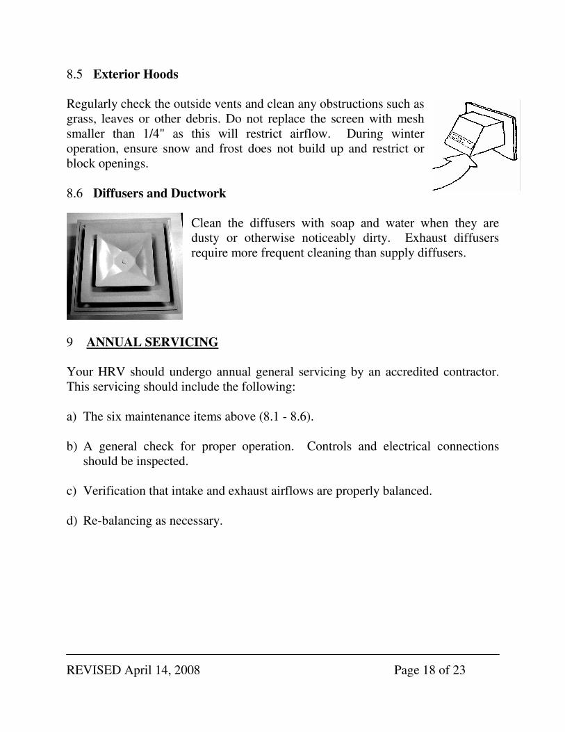
8.5 Exterior Hoods
Regularly check the outside vents and clean any obstructions such as
grass, leaves or other debris. Do not replace the screen with mesh
smaller than 1/4" as this will restrict airflow. During winter
operation, ensure snow and frost does not build up and restrict or
block openings.
8.6 Diffusers and Ductwork
Clean the diffusers with soap and water when they are
dusty or otherwise noticeably dirty. Exhaust diffusers
require more frequent cleaning than supply diffusers.
9 ANNUAL SERVICING
Your HRV should undergo annual general servicing by an accredited contractor.
This servicing should include the following:
a) The six maintenance items above (8.1 - 8.6).
b) A general check for proper operation. Controls and electrical connections
should be inspected.
c) Verification that intake and exhaust airflows are properly balanced.
d) Re-balancing as necessary.

REVISED April 14, 2008 Page 19 of 23
10 TROUBLE SHOOTING SYMPTOM EXPLANATION ANSWER
Frosting up of HRV and/or
Duct(s). •••• HRV air flows incorrectly
balanced.
•••• HRV defrost system is not
working.
•••• Balance HRV.
•••• Install dampers.
•••• Check defrost system.
•••• Note minimal frost build up is
expected on cores before unit
initiates defrost cycle function.
Supply air feels cool. •••• HRV air flows incorrectly
balanced.
•••• Improper location of supply grills.
•••• Velocity of air is too high.
•••• Extremely cold outside
temperatures.
•••• Heating coil is not working.
•••• Balance HRV.
•••• Locate grills high on walls or in
ceiling.
•••• Adjust diffusers, resize duct.
•••• Add a duct heater.
•••• Call your service contractor.
Outside duct has ice build up or
condensation. •••• Improperly installed vapour barrier
around insulated duct.
•••• Tape all joints.
•••• Ensure the vapour barrier is
completely sealed and insulated.
Water in the bottom of HRV. •••• Drain pans are plugged.
•••• Incorrect connections of HRV
drain lines.
•••• HRV is not level.
•••• Drain lines plugged.
•••• HRV heat exchange core
improperly installed.
•••• Look for kinks in the line.
•••• Check water drain connections.
•••• Ensure that water drains from pan.
Poor air flow(s). •••• HRV incorrectly balanced.
•••• Filters need to be cleaned.
•••• Hoods needs to be cleaned.
•••• Grills are closed.
•••• Inline dampers are closed.
•••• Low power supply.
•••• Wrong size ducting.
•••• Under-sized HRV.
•••• HRV is not working.
•••• Tape all joints.
•••• Use proper airflow measuring
equipment.
•••• Open grills.
•••• Remove obstructions in duct(s),
hoods(s), and grill(s).
•••• Balance airflow.
•••• Clean filter.
•••• Have a professional look at the
system.
Humidity levels too low. •••• HRV air flows incorrectly
balanced.
•••• Dehumidistat control set too low.
•••• Balance Air Flow(s).
•••• Increase Dehumidistat.
•••• Humidifiers may need to be added.
Humidity levels too high. •••• HRV air flows incorrectly
balanced.
•••• HRV undersized.
•••• High humidity areas not ventilated
properly.
•••• Dehumidistat is not working.
•••• Balance airflow.
•••• Set dehumidistat.
Dehumidistat is not working. •••• Incorrect connection of outside low
voltage wiring between HRV and
Dehumidistat.
•••• Check outside wiring for short.
•••• Check wall switch for correct
connection.
•••• Check wires are connected to
proper terminals at the HRV.
IMPORTANT! QUALIFIED TECHNICIANS SHOULD DO ALL OTHER SERVICING.

REVISED April 14, 2008 Page 20 of 23
10.1 Electronic Self-Resetting Fuse:
Field mis-wiring of timers or dehumidistats may cause the fuse to trip. If this
happens, remove the control wires and allow the fuse to reset. This may take a few
minutes. Check your manual for proper wiring connections.
10.2 Troubleshooting using the PCB light:
There is a small green light on the board located just below the DIP switches. This
light will either be solid or pulsing and is an indicator of machine status. It can be
used to assist in troubleshooting.
Machine State Light Status
Machine has no power Off
Power to the board, but main power switch
is off or the door switch is tripped
Two short pulses approximately every 5
seconds
Machine running normally in low speed Pulsing – on for one second, off for one
second
Machine running in high speed due to a
call from dehumidistat, timer, or defrost
cycle
Solid
REVISED April 14, 2008 Page 21 of 23
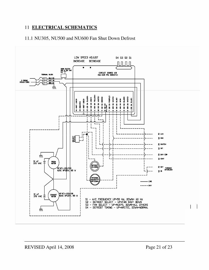
11 ELECTRICAL SCHEMATICS
11.1 NU305, NU500 and NU600 Fan Shut Down Defrost

REVISED April 14, 2008 Page 22 of 23
11.2 NU305, NU500 and NU600 Damper Defrost

REVISED April 14, 2008 Page 23 of 23
12 WARRANTY
NU-AIR LIGHT COMMERCIAL HRV/ERV
NU305, NU500, NU600
WARRANTY
Nu-Air warrants its Light Commercial HRV/ERV to be free from defects on all
components including motors, circuit boards, transformers, and switches when
subject to normal and proper use for a period of two (2) years from the date of
purchase. Nu-Air warrants its aluminum and polypropylene Light Commercial
HRV cores to be free from defects for a period of fifteen (15) years. Latent cores
carry a one (1) year warranty.
Should a manufacturing defect occur during the warranty period, Nu-Air will
supply replacement parts FOB our plant at no charge. Labour costs to remove and
reinstall these parts are not covered under this warranty.
This warranty is expressly in lieu of all other warranties or obligations and in no
event shall Nu-Air be liable for consequential or incidental damages of any kind,
including damage to the building, its contents or any person therein.
Earl Caldwell
President
P.O. Box 2758, Windsor, Nova
Scotia, Canada, B0N 2T0
Phone: (902) 798 2261 Fax: (902) 798 2557
Email: [email protected] Website: www.nu-airventilation.com