operating, maintaining & installing your...
TRANSCRIPT
Rev 2.0 July 15, 2103 1
OPERATING, MAINTAINING & INSTALLING YOUR LIGHT
COMMERCIAL HEAT RECOVERY VENTILATOR
IMPORTANT – READ AND SAVE THESE INSTRUCTIONS
* LEAVE THIS DOCUMENT WITH THE BUILDING OWNER
Specifications, dimensions and ratings may change without notice
due to ongoing product development and improvements.
For products using controller NU-HRV Rev F manufactured April 2013 or later
NU0103, NU0305, NU0406, NU0508, NU0912, NU1316
NU305, NU500, NU600, NU800, NU1200, NU1600
INSTALLATION AND WIRING MUST BE IN ACCORDANCE WITH CEC, NEC AND
LOCAL ELECTRICAL CODES.
P.O. Box 2758
Windsor, Nova Scotia, B0N 2T0
Ph. 902-798-2261 Fax: 902-798-2557
www.nu-airventilation.com
E-mail: [email protected]
Rev 2.0 July 15, 2103 2
NOTE
Prior to integrating this unit with any other piece of mechanical equipment, i.e. furnace, air handler,
combustion heating appliance, careful consideration must be given to system design and integration to
ensure compatibility and proper operation of both appliances. Do not connect the duct system of your
H/ERV to any clothes dryer or kitchen exhaust fan duct system.
Whether installing this unit as part of an independent system or to integrate it with a central
heating/cooling system, use the procedure in this manual to ensure that the air flows of the H/ERV are
balanced. Only a properly balanced H/ERV will deliver maximum performance and energy efficiency.
Although this document contains guidelines for proper HRV sizing and installation, your ventilation
system should be installed in conformance to the appropriate provincial or state building regulations or
National Building Code and/or ASHRAE “Good Engineering Practices”.
IMPORTANT
PLEASE READ THIS MANUAL BEFORE YOU INSTALL OR SERVICE UNIT
AVOID RISK OF INJURY, ELECTRIC SHOCK AND FIRE HAZARD
DO NOT install this product in an unconditioned space—15º C/59º F ambient temperature is recommended—or in a
space/manner where maintenance and service might a pose risk of personal injury or damage to this product.
For indoor installations only.
If your H/ERV is equipped with a 3-prong plug which will fit an A/C electrical outlet in just one orientation. Do not alter this
plug or its cord in any way. Grip the plug firmly when removing it from an electrical outlet—NEVER unplug this product by
pulling or twisting its power cord.
ALWAYS unplug an H/ERV before you open or remove its cover (door) to clean the inside of the unit or for any other
servicing or repairs.
The cover to this H/ERV is removable to ensure ease of access to internal components during cleaning and servicing.
USE CAUTION when opening or removing the cover of this H/ERV to avoid risk of personal injury or damage to the cover.
NEVER attempt to clean the interior of this H/ERV or its components while the unit is plugged in or running.
ONLY qualified persons should attempt repair or service of any electrical/internal component of this product.
NEVER attempt to repair or service any internal component of this H/ERV while the unit is plugged in or running.
DO NOT use your ventilation system to exhaust flammable fumes or gasses.
ALWAYS contact your Nu-Air representative if you have any questions or comments about the operation or maintenance
of your Nu-Air H/ERV—we are here to help you!
ALWAYS contact your Nu-Air representative if you have any questions or comments about the operation or maintenance
of your Nu-Air H/ERV—we are here to help you!
Rev 2.0 July 15, 2103 3
Contents 1 How the NU-AIR System Works ............................................................................................................ 4
2 Features and Operation ........................................................................................................................ 4
3 Installation Instructions ........................................................................................................................ 4
3.1 Installer’s Responsibilities ............................................................................................................. 4
3.2 Installation Basics .......................................................................................................................... 5
3.3 Ductwork ....................................................................................................................................... 5
3.4 Weather Hoods ............................................................................................................................. 6
3.5 Port Configurations ....................................................................................................................... 7
3.6 Mounting and Noise Control ......................................................................................................... 7
3.7 Drain Connections ......................................................................................................................... 8
4 Connecting to Other Equipment ........................................................................................................... 9
5 External Connections ............................................................................................................................ 9
6 Unit Controls: Operation and Wiring .................................................................................................... 9
6.1 ES Series Controls (12 VDC)........................................................................................................... 9
6.1.1 ES Control Wiring ................................................................................................................ 11
6.2 Winsor Series & Other 24 VAC Control Options ......................................................................... 12
6.2.1 Standard Dehumidistat (Part # DSTAT-1) & 2-wire switches .............................................. 12
6.2.2 Windsor Control (Part # WIN-1) .......................................................................................... 12
6.2.3 Windsor Timer (WIN-20) ..................................................................................................... 13
7 Control Board Status LEDs .................................................................................................................. 13
8 Selectable Furnace/Air Handler Interlock ........................................................................................... 14
8.1 Furnace/Air Handler Interlock Wiring ......................................................................................... 14
9 Defrost Operation ............................................................................................................................... 15
10 Balancing the System ...................................................................................................................... 15
10.1 Balancing Procedure: NU0103/NU305, NU0305/NU500, NU0406/NU600 ................................ 16
10.2 Balancing Procedure: NU0508/NU800, NU0912/NU1200, NU1316/NU1600 ............................ 17
11 Maintenance ................................................................................................................................... 18
12 Troubleshooting .............................................................................................................................. 19
13 Electrical Schematics ....................................................................................................................... 20
14 Warranty ......................................................................................................................................... 37
Rev 2.0 July 15, 2103 4
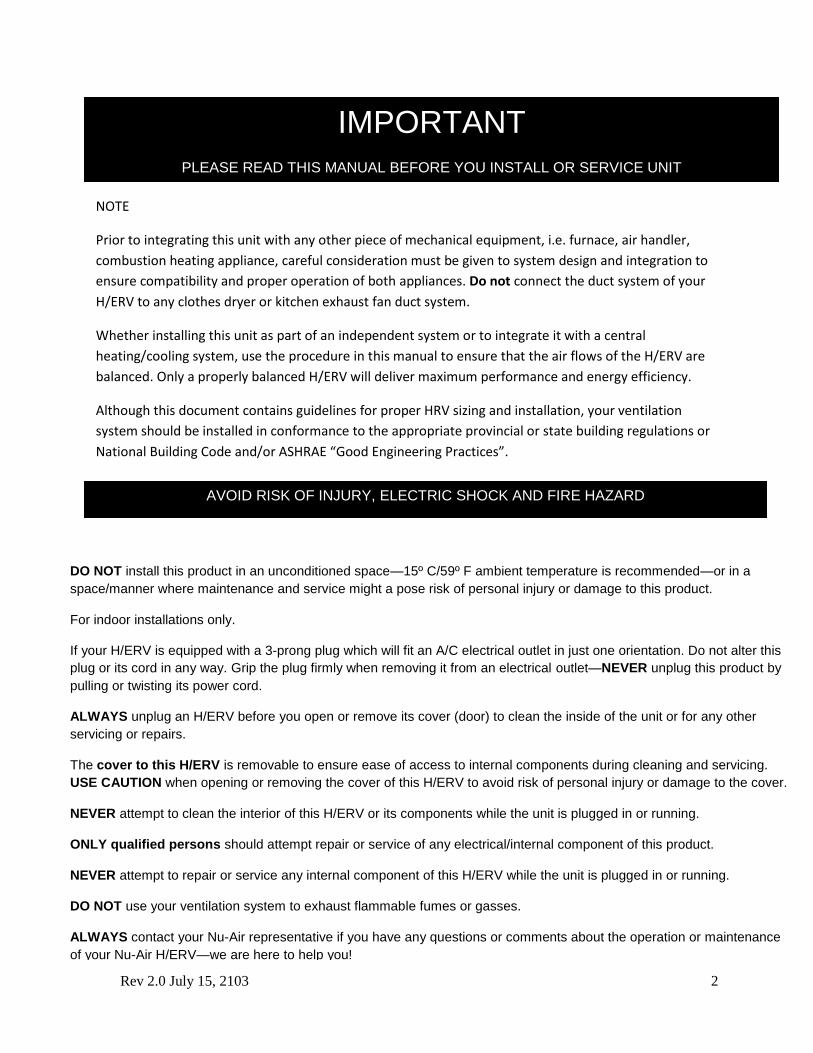
1 How the NU-AIR System Works
This heat recovery ventilator (HRV) provides fresh air to a conditioned space while exhausting
an equal amount of stale air. Heat energy is transferred from one air stream to the other within a
non-contact cross flow heat exchanger.
Two forward curve blowers work to bring fresh air into the space and exhaust an equal
amount of stale air.
Incoming fresh air is filtered before flowing through the heat exchange core.
Stale, humid air flows through the cross-flow heat exchanger and transfers the heat to the
incoming fresh air.
Warm fresh air is distributed through an independent ductwork system or an existing air
distribution system.
2 Features and Operation
These models use microprocessor based control technology.
The standard control configurations of these HRV’s consist of two speed settings selectable from
a remote control. Connection between the HRV and control is achieved through low voltage
wiring.
Features include:
Powerful transformer
Intelligent defrost.
Self-resetting fuse to protect the board against mis-wiring.
Motor speed control (NU0103, NU0305, NU0406 only) – Motors can be independently
adjusted in HRV high and low speeds. Optional setting for 220V/50Hz geographic areas.
Fan interlock
3 Installation Instructions
3.1 Installer’s Responsibilities
Installers are responsible for the performance of the ventilation system and for ensuring that all
codes and standards are met.
Do not mount the fresh air supply near a source of contaminated air such as automotive exhaust,
gas or propane exhaust or oil tanks.
Combustion appliances such as furnaces and hot water heaters must not draw combustion air
directly from an H/ERV.
Rev 2.0 July 15, 2103 5
3.2 Installation Basics
Before installing a Nu-Air Light Commercial H/ERV for the first time, please read these
instructions.
1. Standard Issue Items
The HRV comes equipped with:
Filters
Heat/Energy Recovery Core
Drain Kit
Anti-Vibration straps (NU0103, NU0305)
Anti-vibration Springs, chain & hanging brackets
(NU0406)
2. Other Basic Needs
Control Package
Galvanized Duct
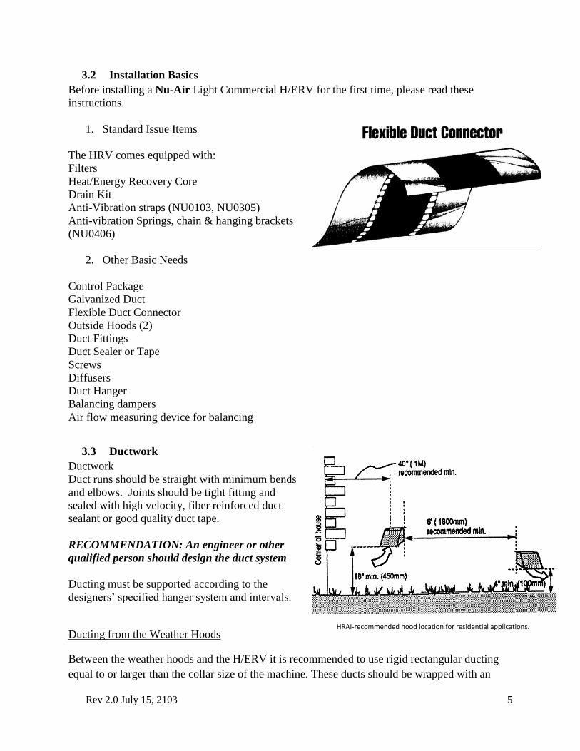
Flexible Duct Connector
Outside Hoods (2)
Duct Fittings
Duct Sealer or Tape
Screws
Diffusers
Duct Hanger
Balancing dampers
Air flow measuring device for balancing
3.3 Ductwork
Ductwork
Duct runs should be straight with minimum bends
and elbows. Joints should be tight fitting and
sealed with high velocity, fiber reinforced duct
sealant or good quality duct tape.
RECOMMENDATION: An engineer or other
qualified person should design the duct system
Ducting must be supported according to the
designers’ specified hanger system and intervals.
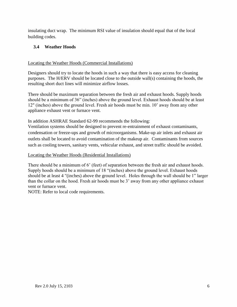
Ducting from the Weather Hoods
Between the weather hoods and the H/ERV it is recommended to use rigid rectangular ducting
equal to or larger than the collar size of the machine. These ducts should be wrapped with an
HRAI-recommended hood location for residential applications.
Rev 2.0 July 15, 2103 6
insulating duct wrap. The minimum RSI value of insulation should equal that of the local
building codes.
3.4 Weather Hoods
Locating the Weather Hoods (Commercial Installations)
Designers should try to locate the hoods in such a way that there is easy access for cleaning
purposes. The H/ERV should be located close to the outside wall(s) containing the hoods, the
resulting short duct lines will minimize airflow losses.
There should be maximum separation between the fresh air and exhaust hoods. Supply hoods
should be a minimum of 36” (inches) above the ground level. Exhaust hoods should be at least
12" (inches) above the ground level. Fresh air hoods must be min. 10’ away from any other
appliance exhaust vent or furnace vent.
In addition ASHRAE Standard 62-99 recommends the following:
Ventilation systems should be designed to prevent re-entrainment of exhaust contaminants,
condensation or freeze-ups and growth of microorganisms. Make-up air inlets and exhaust air
outlets shall be located to avoid contamination of the makeup air. Contaminants from sources
such as cooling towers, sanitary vents, vehicular exhaust, and street traffic should be avoided.
Locating the Weather Hoods (Residential Installations)
There should be a minimum of 6’ (feet) of separation between the fresh air and exhaust hoods.
Supply hoods should be a minimum of 18 “(inches) above the ground level. Exhaust hoods
should be at least 4 "(inches) above the ground level. Holes through the wall should be 1” larger
than the collar on the hood. Fresh air hoods must be 3’ away from any other appliance exhaust
vent or furnace vent.
NOTE: Refer to local code requirements.
Rev 2.0 July 15, 2103 7
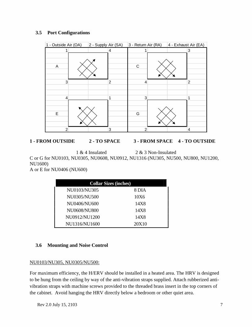
3.5 Port Configurations
1 - FROM OUTSIDE 2 - TO SPACE 3 - FROM SPACE 4 - TO OUTSIDE
1 & 4 Insulated 2 & 3 Non-Insulated
C or G for NU0103, NU0305, NU0608, NU0912, NU1316 (NU305, NU500, NU800, NU1200,
NU1600)
A or E for NU0406 (NU600)
3.6 Mounting and Noise Control
NU0103/NU305, NU0305/NU500:
For maximum efficiency, the H/ERV should be installed in a heated area. The HRV is designed
to be hung from the ceiling by way of the anti-vibration straps supplied. Attach rubberized anti-
vibration straps with machine screws provided to the threaded brass insert in the top corners of
the cabinet. Avoid hanging the HRV directly below a bedroom or other quiet area.
1 - Outside Air (OA) 2 - Supply Air (SA) 3 - Return Air (RA) 4 - Exhaust Air (EA)
1 4 1 3
A C
3 2 4 2
4 1 3 1
E G
2 3 2 4
Collar Sizes (inches)
NU0103/NU305 8 DIA
NU0305/NU500 10X6
NU0406/NU600 14X8
NU0608/NU800 14X8
NU0912/NU1200 14X8
NU1316/NU1600 20X10
Rev 2.0 July 15, 2103 8
NU0406 – NU1316 & NU600-NU1600:
The H/ERV is designed to be hung from the ceiling by way of
the anti-vibration springs and chain supplied. You will also need
bolt cutters or snips and self-tapping screws. The following
items are included with the H/ERV:
Galvanized suspension bracket (4)
#10-24 x 1/2" machine screw, Robertson socket drive
(16)
Suspension Springs (4)
Double loop suspension chain (20')
Securely fasten the bracket to the HRV with the machine screws
supplied. (A)
Cut the suspension chain into four equal lengths (5' max).
Use a self-tapping screw to fasten the first complete link of
chain to the pre-drilled hole in the bracket. (B)
Hook the chain into the grab slot of the bracket. Note that the
tension of the chain must pull toward the middle of the bracket.
Use the appropriate slot for this effect. ( C )
Attach the free end of the chain to a structurally sound member overhead. This will vary from
site to site.
Form a 5" loop in the chain and hook the vibration isolation spring between the slack. (D)
IMPORTANT: A. Do not rely on the spring to hold up the HRV without chain back up. B.
Flexible duct connector (PRO flex or other) should be used at all four collars of the H/ERV to
isolate vibration.
3.7 Drain Connections
Access to a drain is required to handle the HRV
condensate. Care should be taken to run the condensate
tube where it will not freeze.
For best results, Nu-Air recommends the following steps
be followed when installing drain kits.
1. Apply the O-ring supplied to the flange of each
drain spout. (A)
2. Insert the drain spouts through the holes in the
drain pan. (B)
3. Use the speed nut to tightly secure the drain
spout.
4. Cut two lengths of drain hose long enough to
avoid kinking. (E)
5. Attach the hose to the drain spout by sliding it over the spout until it is tight to the bottom
of the speed nut.
Rev 2.0 July 15, 2103 9
6. Secure the hose to the spout with the plastic tie wraps. (D)
7. Install the tee fitting as shown in the drawing below. (F)
8. Attach the free end of the hose to the left fitting. Repeat for the other side.
9. Use the remaining hose to form a "P" trap and terminate at the top of the tee.
10. Pour water into the drain assembly to form an air seal. This prevents gasses from being
drawn into the HRV.
4 Connecting to Other Equipment
In general the H/ERV is not intended to be connected to other equipment or appliances.
Connection with a forced air furnace or air handler is common practice but additional controls
must be in place.
If the H/ERV is used upstream of an air handler or similar equipment (e.g. fresh air into
economizer section), the start-up sequence must be H/ERV first followed by the air handler.
Starting the air handler first, will rotate the H/ERV's fresh air fan backward. If the motor is
unable to overcome the extra load an over amp situation will result.
5 External Connections
For electrical hook-up, the H/ERV should be connected to its own circuit using electrical wire
and conduit in accordance with code requirements.
Nu-Air H/ERVs are equipped for remote controls. Options include occupancy, humidity and gas
sensors, timers, off/on/intermittent-on, and low-high switching.
6 Unit Controls: Operation and Wiring
Your unit is equipped with 12 VDC and 24 VAC removable terminal blocks. The control logic of the unit
circuit board is such that the most recently used remote control will control the unit. If desired, 12 VDC
and 24 VAC controls may be used in the same installation. Use a 3 mm flat-head screwdriver to connect
wires to the terminal blocks.
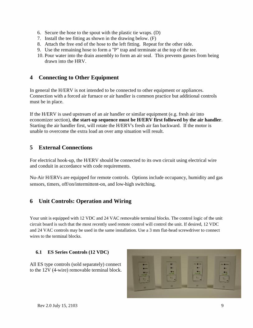
6.1 ES Series Controls (12 VDC)
All ES type controls (sold separately) connect
to the 12V (4-wire) removable terminal block.
Rev 2.0 July 15, 2103 10
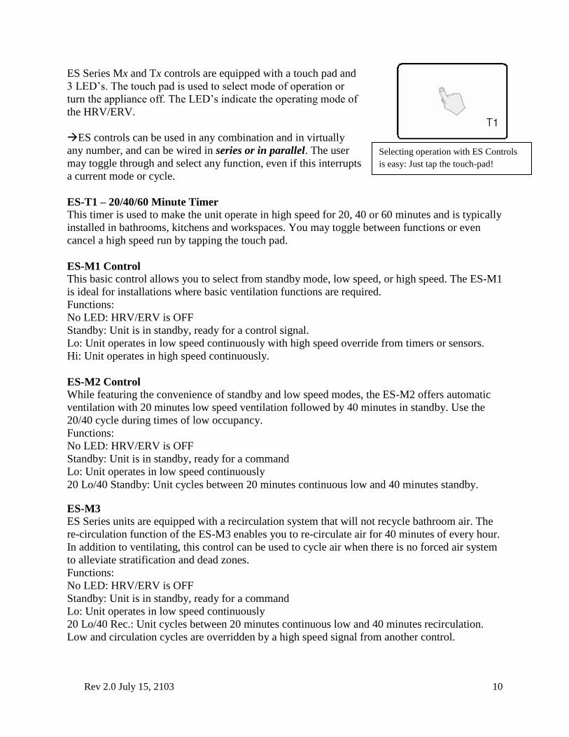
ES Series Mx and Tx controls are equipped with a touch pad and
3 LED’s. The touch pad is used to select mode of operation or
turn the appliance off. The LED’s indicate the operating mode of
the HRV/ERV.
ES controls can be used in any combination and in virtually
any number, and can be wired in series or in parallel. The user
may toggle through and select any function, even if this interrupts
a current mode or cycle.
ES-T1 – 20/40/60 Minute Timer
This timer is used to make the unit operate in high speed for 20, 40 or 60 minutes and is typically
installed in bathrooms, kitchens and workspaces. You may toggle between functions or even
cancel a high speed run by tapping the touch pad.
ES-M1 Control
This basic control allows you to select from standby mode, low speed, or high speed. The ES-M1
is ideal for installations where basic ventilation functions are required.
Functions:
No LED: HRV/ERV is OFF
Standby: Unit is in standby, ready for a control signal.
Lo: Unit operates in low speed continuously with high speed override from timers or sensors.
Hi: Unit operates in high speed continuously.
ES-M2 Control
While featuring the convenience of standby and low speed modes, the ES-M2 offers automatic
ventilation with 20 minutes low speed ventilation followed by 40 minutes in standby. Use the
20/40 cycle during times of low occupancy.
Functions:
No LED: HRV/ERV is OFF
Standby: Unit is in standby, ready for a command
Lo: Unit operates in low speed continuously
20 Lo/40 Standby: Unit cycles between 20 minutes continuous low and 40 minutes standby.
ES-M3
ES Series units are equipped with a recirculation system that will not recycle bathroom air. The
re-circulation function of the ES-M3 enables you to re-circulate air for 40 minutes of every hour.
In addition to ventilating, this control can be used to cycle air when there is no forced air system
to alleviate stratification and dead zones.
Functions:
No LED: HRV/ERV is OFF
Standby: Unit is in standby, ready for a command
Lo: Unit operates in low speed continuously
20 Lo/40 Rec.: Unit cycles between 20 minutes continuous low and 40 minutes recirculation.
Low and circulation cycles are overridden by a high speed signal from another control.
Selecting operation with ES Controls
is easy: Just tap the touch-pad!
Rev 2.0 July 15, 2103 11
G
A
B
12
UN
IT 12
VD
C R
EMO
VA
BLE
TERM
INA
L BLO
CK
ES SERIES CONTROL
+12
B
A
G
ES-M4
The ES-M4 control offers the simplicity of the ES-M1, with the added convenience of full-time
recirculation mode.
Functions:
No LED: HRV/ERV is OFF
Standby: Unit is in standby, ready for a command
Lo: Unit operates in low speed continuously
Rec.: Unit operates in full-time recirculation with no outdoor air exchange.4
Low and circulation cycles are overridden by a high speed signal from another control.
M4 can only be used with HRV equipped with recirculation capability: NU0103, NU0305, NU0406, NU0508, NU0912, NU1316
with circulation defrost.
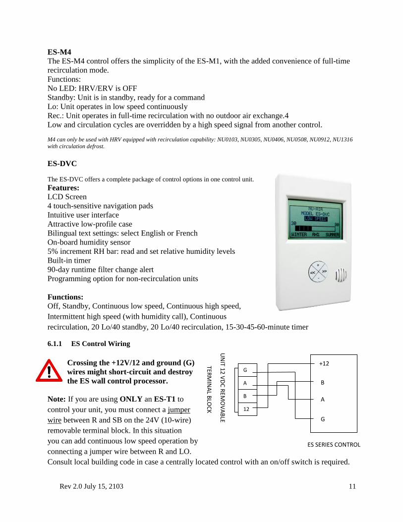
ES-DVC
The ES-DVC offers a complete package of control options in one control unit.
Features:
LCD Screen
4 touch-sensitive navigation pads
Intuitive user interface
Attractive low-profile case
Bilingual text settings: select English or French
On-board humidity sensor
5% increment RH bar: read and set relative humidity levels
Built-in timer
90-day runtime filter change alert
Programming option for non-recirculation units
Functions:
Off, Standby, Continuous low speed, Continuous high speed,
Intermittent high speed (with humidity call), Continuous
recirculation, 20 Lo/40 standby, 20 Lo/40 recirculation, 15-30-45-60-minute timer
6.1.1 ES Control Wiring
Crossing the +12V/12 and ground (G)
wires might short-circuit and destroy
the ES wall control processor.
Note: If you are using ONLY an ES-T1 to
control your unit, you must connect a jumper
wire between R and SB on the 24V (10-wire)
removable terminal block. In this situation
you can add continuous low speed operation by
connecting a jumper wire between R and LO.
Consult local building code in case a centrally located control with an on/off switch is required.
Rev 2.0 July 15, 2103 12
UN
IT 24
VA
C R
EMO
VA
BLE TER
MIN
AL B
LOC
K
NC
I
NO
R
C
TL
TS
SB
Hi
LO
JUM
PER
WIR
E
JUM
PER
WIR
E
PURPLE
PURPLE
DSTAT-1
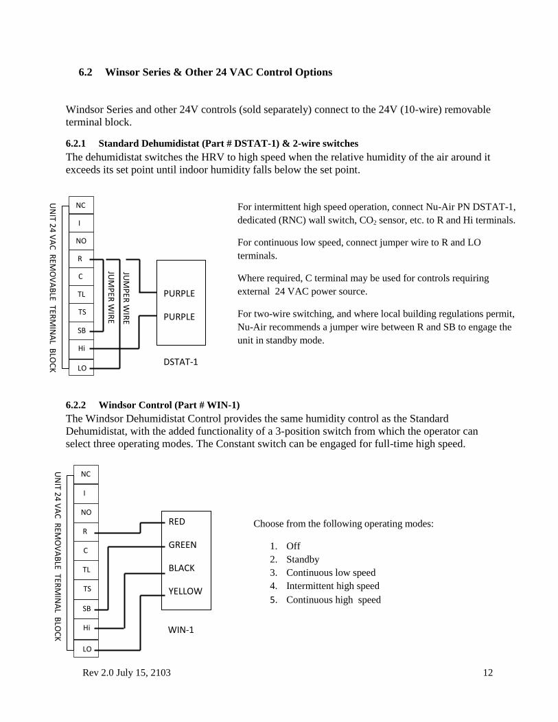
For intermittent high speed operation, connect Nu-Air PN DSTAT-1,
dedicated (RNC) wall switch, CO2 sensor, etc. to R and Hi terminals.
For continuous low speed, connect jumper wire to R and LO
terminals.
Where required, C terminal may be used for controls requiring
external 24 VAC power source.
For two-wire switching, and where local building regulations permit,
Nu-Air recommends a jumper wire between R and SB to engage the
unit in standby mode.
UN
IT 24
VA
C R
EMO
VA
BLE TER
MIN
AL B
LOC
K
NC
I
NO
R
C
TL
TS
SB
Hi
LO
RED
GREEN
BLACK
YELLOW
WIN-1
Choose from the following operating modes:
1. Off
2. Standby
3. Continuous low speed
4. Intermittent high speed
5. Continuous high speed
6.2 Winsor Series & Other 24 VAC Control Options
Windsor Series and other 24V controls (sold separately) connect to the 24V (10-wire) removable
terminal block.
6.2.1 Standard Dehumidistat (Part # DSTAT-1) & 2-wire switches
The dehumidistat switches the HRV to high speed when the relative humidity of the air around it
exceeds its set point until indoor humidity falls below the set point.
6.2.2 Windsor Control (Part # WIN-1)
The Windsor Dehumidistat Control provides the same humidity control as the Standard
Dehumidistat, with the added functionality of a 3-position switch from which the operator can
select three operating modes. The Constant switch can be engaged for full-time high speed.
Rev 2.0 July 15, 2103 13
UN
IT 24
VA
C R
EMO
VA
BLE TER
MIN
AL B
LOC
K
NC
I
NO
R
C
TL
TS
SB
Hi
LO
PWR (red)
LED (yellow)
SWITCH (black)
WIN-20
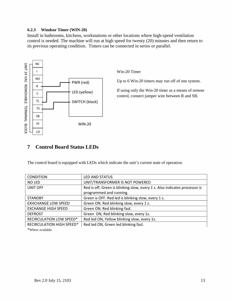
Win-20 Timer
Up to 6 Win-20 timers may run off of one system.
If using only the Win-20 timer as a means of remote
control, connect jumper wire between R and SB.
6.2.3 Windsor Timer (WIN-20)
Install in bathrooms, kitchens, workstations or other locations where high-speed ventilation
control is needed. The machine will run at high speed for twenty (20) minutes and then return to
its previous operating condition. Timers can be connected in series or parallel.
7 Control Board Status LEDs
The control board is equipped with LEDs which indicate the unit’s current state of operation.
*Where available
CONDITION LED AND STATUS
NO LED UNIT/TRANSFORMER IS NOT POWERED
UNIT OFF Red is off, Green is blinking slow, every 1 s. Also indicates processor is programmed and running.
STANDBY Green is OFF. Red led is blinking slow, every 1 s.
EXHCHANGE LOW SPEED Green ON. Red blinking slow, every 1 s.
EXCHANGE HIGH SPEED Green ON. Red blinking fast.
DEFROST Green ON, Red blinking slow, every 1s.
RECIRCULATION LOW SPEED* Red led ON, Yellow blinking slow, every 1s.
RECIRCULATION HIGH SPEED* Red led ON, Green led blinking fast.
Rev 2.0 July 15, 2103 14
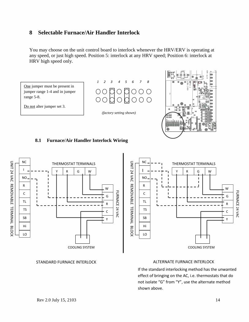
8 Selectable Furnace/Air Handler Interlock
You may choose on the unit control board to interlock whenever the HRV/ERV is operating at
any speed, or just high speed. Position 5: interlock at any HRV speed; Position 6: interlock at
HRV high speed only.
8.1 Furnace/Air Handler Interlock Wiring
One jumper must be present in
jumper range 1-4 and in jumper
range 5-8.
Do not alter jumper set 3.
1 2 3 4 5 6 7 8
(factory setting shown)
NC
I
NO
R
C
TL
TS
SB
Hi
LO
UN
IT 24
VA
C R
EMO
VA
BLE TER
MIN
AL B
LOC
K
THERMOSTAT TERMINALS
Y R G W
W
G
R
C
Y
COOLING SYSTEM
FUR
NA
CE
24
VA
C
NC
I
NO
R
C
TL
TS
SB
Hi
LO U
NIT 2
4 V
AC
REM
OV
AB
LE TERM
INA
L BLO
CK
THERMOSTAT TERMINALS
Y R G W
W
G
R
C
Y
COOLING SYSTEM
FUR
NA
CE
24
VA
C
STANDARD FURNACE INTERLOCK ALTERNATE FURNACE INTERLOCK
If the standard interlocking method has the unwanted
effect of bringing on the AC, i.e. thermostats that do
not isolate “G” from “Y”, use the alternate method
shown above.
Rev 2.0 July 15, 2103 15
9 Defrost Operation
Proportional Defrost Cycles
Your unit will adjust defrost frequency and duration, based on outdoor temperature: -5º C (23º F)
-15º C (5º F), -20º C (-4º F) and -27º C (-17º F).
Circulation Defrost:
When outdoor temperature is below -5º C (23º F), a defrost cycle is initiated for a fixed duration.
The fresh air motor will run and the exhaust air motor will shut down. A damper will shut off the
cold supply port, directing ambient air through the core for defrosting. The unit will resume
normal operation for a fixed duration, then the processor will read outdoor temperature and
initiate defrost as necessary. Defrost times and intervals will vary according to temperature
below -5º C (23º F).
Timed Fan Shut-Down Defrost:
The outside air before the core is monitored. When below freezing, a timed defrost cycle is
activated. The supply fan shuts down while the exhaust fan continues to move warm air through
the core. After a predefined temperature based time cycle, the HRV reverts to exchange mode.
NOTE: In circulation defrost mode, this unit will not induce indoor negative pressure nor recycle
exhaust air; rather it will redistribute ambient room air.
10 Balancing the System
Once the H/ERV system is installed, do the following:
1. Close all windows and doors.
2. Turn off any exhaust only systems.
3. To balance the H/ERV, set the machine on high speed.
4. Make a small hole in the supply duct at least 2 feet down stream of the motor. Insert a
Pitot tube in the cross sectional center of the duct.
5. Measure the velocity pressure with a digital manometer or magnehelic gauge.
6. Record the value and repeat the procedure for the exhaust air stream.
7. Use the motor speed control buttons on the side of the unit to reduce airflow until the
velocity pressure equals that of the opposite air stream, unless otherwise described below.
To balance the H/ERV, you will need a device to measure air flow. It is recommended to use
either a magnehelic gauge or a pitot tube air meter (discussed here). Depending on the device
you are using, follow one of the two procedures below:
Rev 2.0 July 15, 2103 16
Digital Manometer & Pitot Tube (Supplied by Others)
Magnehelic Gauge: (Part # 2000-00 – not shown)
1. Disengage one end of the exhaust flexible duct connector in the main duct before any branch
ducts and push the duct back into itself. Insert the flow grid and tape the joint between the
flow grid and ductwork.
2. Set the HRV on high speed. Mount the magnehelic gauge level and plumb. Join the hoses
from the flow grid to the magnehelic gauge. The needle of the magnehelic gauge should read
positively. Switch hose connections if the needle falls below zero.
3. Record reading from gauge. Repeat the procedure for the supply duct.
4. Go back to the duct with the higher reading and adjust the motor speed until the supply air is
equal to the exhaust air reading.
460 Air Meter: (Nu-Air Part #100460).
1. Drill a ¼” hole in both the supply and exhaust ducts on the warm-side of the
machine at least 12” away from the HRV and any elbows, tees, etc.
2. Set the H/ERV on high speed.
3. Take a pressure reading in each duct and record the results.
4. Go back to the duct having the higher reading, and using the motor speed
control buttons reduce the airflow down until the pressure reads to within 10%
of the other air flow.
5. Use tape to reseal the holes.
6. To convert pressure readings to airflow (cfm or L/s) refer to the instructions
and table included with the air meter.
10.1 Balancing Procedure: NU0103/NU305, NU0305/NU500, NU0406/NU600
Balanced air flow between the supply and exhaust air streams is essential to the performance of
an HRV or ERV. Changing motor speeds or balancing is quick and simple with two buttons
recessed slightly into the unit’s cabinet. NO BALANCING DAMPERS ARE REQUIRED. Be
Rev 2.0 July 15, 2103 17
sure to close windows and doors, and turn off all exhaust fans/appliances during the balancing
procedure.
High-Speed Adjustment/Balancing:
1. Use any means to initiate high speed (e.g. ES-M1 control, R—H jumper wire, or 24V
R—H control) may be used. Remove the jumper wires after balancing.
2. Press and hold either the FRESH air or EXHAUST air pushbuttons (not both) for 3
Seconds. Releasing the push-button places the unit in SPEED ADJUST MODE.
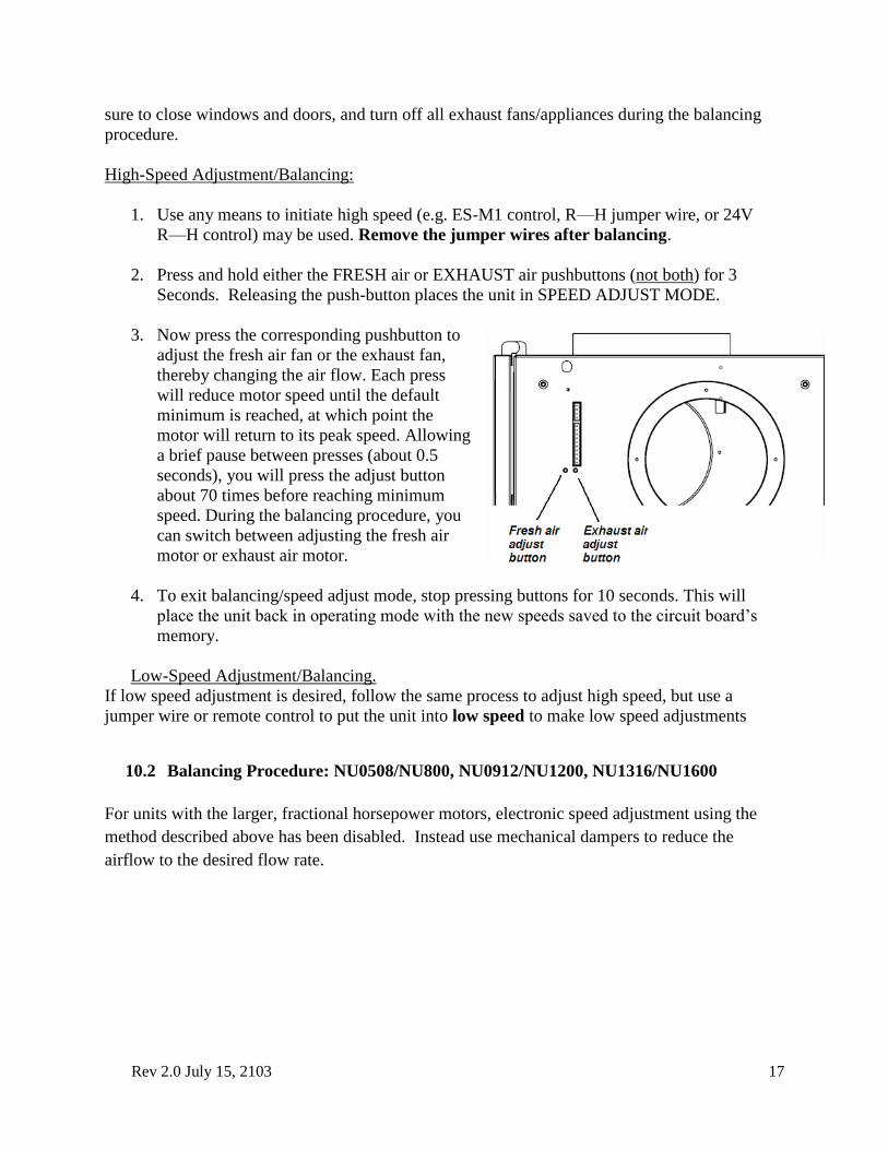
3. Now press the corresponding pushbutton to
adjust the fresh air fan or the exhaust fan,
thereby changing the air flow. Each press
will reduce motor speed until the default
minimum is reached, at which point the
motor will return to its peak speed. Allowing
a brief pause between presses (about 0.5
seconds), you will press the adjust button
about 70 times before reaching minimum
speed. During the balancing procedure, you
can switch between adjusting the fresh air
motor or exhaust air motor.
4. To exit balancing/speed adjust mode, stop pressing buttons for 10 seconds. This will
place the unit back in operating mode with the new speeds saved to the circuit board’s
memory.
Low-Speed Adjustment/Balancing.
If low speed adjustment is desired, follow the same process to adjust high speed, but use a
jumper wire or remote control to put the unit into low speed to make low speed adjustments
10.2 Balancing Procedure: NU0508/NU800, NU0912/NU1200, NU1316/NU1600
For units with the larger, fractional horsepower motors, electronic speed adjustment using the
method described above has been disabled. Instead use mechanical dampers to reduce the
airflow to the desired flow rate.
Rev 2.0 July 15, 2103 18
11 Maintenance
Note: The following are minimal service guidelines. More frequent maintenance will be
required depending on service application and conditions. CAUTION: Disconnect power before
servicing.
Filters
Dirty filters can reduce ventilation efficiency, result in unbalanced airflow and damage or
shorten the life of the motors. Clean at least every three months. Polyester filters should be
vacuumed, not washed, and replaced annually. Filters remove easily by opening the front cover.
Fans
When cleaning the filters, take the opportunity to vacuum any interior surfaces including the fan
blades.
Condensate Drain
Twice per year wipe clean the condensate drain pan. Check the condensate drain and tubing to
ensure they are free flowing. The tubing must have an "S" or loop that traps a quantity of water
to prevent air from entering the HRV via this tubing.
Core
The core (heat/energy exchanger) should be removed and cleaned at least once a year. Use a
non-corrosive enzyme detergent in cold water (i.e. Arctic Power). To remove the cover of the
machine, unlatch and slide the door to the right to release from the hinges. Slide the core
forward to remove it from the HRV.
Exterior Hoods
Regularly check the outside vents and clean any obstructions such as grass, leaves or other
debris. Do not replace the screen with mesh smaller than 1/4" as this will restrict airflow. During
winter operation, ensure snow and frost does not build up and restrict or block openings.
Diffusers and Ductwork
Clean the diffusers with soap and water when they are dusty or otherwise noticeably dirty.
Exhaust diffusers require more frequent cleaning than supply diffusers.
ANNUAL SERVICING
Your H/ERV should undergo annual general servicing by an accredited contractor. This
servicing should include the following:
The six maintenance items above.
A general check for proper operation. Controls and electrical connections should be
inspected.
Verification that intake and exhaust airflows are properly balanced.
Re-balancing as necessary.
Rev 2.0 July 15, 2103 19
12 Troubleshooting
SYMPTOM EXPLANATION ANSWER Frosting up of HRV and/or
Duct(s).
HRV air flows incorrectly balanced.
HRV defrost system is not working.
Balance HRV.
Install dampers.
Check defrost system.
Note minimal frost build up is expected
on cores before unit initiates defrost
cycle function.
Supply air feels cool.
HRV air flows incorrectly balanced.
Improper location of supply grills.
Velocity of air is too high.
Extremely cold outside temperatures.
Heating coil is not working.
Balance HRV.
Locate grills high on walls or in ceiling.
Adjust diffusers, resize duct.
Add a duct heater.
Call your service contractor.
Outside duct has ice build-up or
condensation.
Improperly installed vapour barrier
around insulated duct.
Tape all joints.
Ensure the vapour barrier is completely
sealed and insulated.
Water in the bottom of HRV. Drain pans are plugged.
Incorrect connections of HRV drain
lines.
HRV is not level.
Drain lines plugged.
HRV heat exchange core improperly
installed.
Look for kinks in the line.
Check water drain connections.
Ensure that water drains from pan.
Poor air flow(s). HRV incorrectly balanced.
Filters need to be cleaned.
Hoods needs to be cleaned.
Grills are closed.
Inline dampers are closed.
Low power supply.
Wrong size ducting.
Under-sized HRV.
HRV is not working.
Tape all joints.
Use proper airflow measuring
equipment.
Open grills.
Remove obstructions in duct(s),
hoods(s), and grill(s).
Balance airflow.
Clean filter.
Have a professional look at the system.
Humidity levels too low. HRV air flows incorrectly balanced.
Dehumidistat control set too low.
Balance Air Flow(s).
Increase Dehumidistat.
Humidifiers may need to be added.
Humidity levels too high. HRV air flows
incorrectly balanced.
HRV undersized.
High humidity areas not ventilated
properly.
Dehumidistat is not working.
Balance airflow.
Set dehumidistat.
Dehumidistat is not working. Incorrect connection of outside low
voltage wiring between HRV and
Dehumidistat.
Check outside wiring for short.
Check wall switch for correct
connection.
Check wires are connected to proper
terminals at the HRV.
Rev 2.0 July 15, 2103 20
13 Electrical Schematics
There are a number of configurations and options available for these products. The schematic
specific to your unit was supplied with the equipment. The following pages illustrate typical,
generic, schematics. Your equipment may vary.
Rev 2.0 July 15, 2103 21
Rev 2.0 July 15, 2103 22
Rev 2.0 July 15, 2103 23
Rev 2.0 July 15, 2103 24
Rev 2.0 July 15, 2103 25
Rev 2.0 July 15, 2103 26
Rev 2.0 July 15, 2103 27
Rev 2.0 July 15, 2103 28
Rev 2.0 July 15, 2103 29
Rev 2.0 July 15, 2103 30
Rev 2.0 July 15, 2103 31
Rev 2.0 July 15, 2103 32
Rev 2.0 July 15, 2103 33
Rev 2.0 July 15, 2103 34
Rev 2.0 July 15, 2103 35
Rev 2.0 July 15, 2103 36
Rev 2.0 July 15, 2103 37
14 Warranty
NU-AIR Heat/Energy Recovery Ventilator Transferable Warranty
For Canada and United States
Models: NU305, NU500, NU600, NU800, NU1200, NU0103, NU0305, NU0406, NU0508,
NU0912, NU1316
Should your NU-AIR ES Series Heat Recovery Ventilator (HRV) cease to function within two
(2) years of the date of original purchase (effective May 1st
,2012) due to defective material or
workmanship of the product, NU-AIR Ventilation Systems Inc. will supply a new or rebuilt part
FOB Factory to replace the defective part. Delivery, installation, and labour cost are not covered
by this warranty.
Core Warranties
If the polypropylene core in your NU-AIR Heat Recovery Ventilator (HRV) fails due to a defect
in material or workmanship within fifteen (15) years NU-AIR Ventilation Systems Inc. will
supply a new core FOB Factory to replace the defective part. Delivery and labour costs are
customers responsibility.
Nu-Air warrants its Energy Recovery (ERV) core to be free from manufacturing defects for a
period of five (5) years. Delivery and labour costs are customers responsibility.
Warranty Limitations
The above warranty does not cover damage to the unit while in your possession (other than
damages caused by defective parts or material) due to the following: 1) improper installation or
unreasonable use of unit: 2) failure to provide reasonable and necessary maintenance.
P.O. Box 2758 Windsor, Nova Scotia
Canada B0N 2T0
Phone: 902 798 2261 Fax: 902 798 2557
Email: [email protected]
Website: www.nu-airventilation.com
Rev 2.0 July 15, 2103 38
Windsor, Nova Scotia
16 Nelson St.
P.O Box 2758
B0N 2T0 Canada
Ph: 902-798-2261
Fax: 902-798-2557
Email: [email protected] Web: www.nu-airventilation.com
Email: [email protected] Website: www.nu-airventilation.com