operating manual and maintenance instructions · tightening propeller-retaining nuts and engine...
TRANSCRIPT

2010 Clermont Street, Antigo, WI, 54409 •••• Phone: 715-627-5500 or 800-448-2524 •••• Fax: 715-627-5554 Web: http://www.hydratight.com/
Operating Instruction8000-OM
Page 1 of 33
REV: B
Operating Manual and Maintenance Instructions
Propeller & Engine Thrust Nut Tools For use with the SWE8200 Torque Multiplier

2010 Clermont Street, Antigo, WI, 54409 •••• Phone: 715-627-5500 or 800-448-2524 •••• Fax: 715-627-5554 Web: http://www.hydratight.com/
Operating Instruction8000-OM
Page 2 of 33
REV: B
TABLE OF CONTENTS
Section Page Section Page
I. Introduction and Description
1 Introduction 1
1-2 Purpose 1
1-4 Description 1
1-7 Torque Multiplier SWE8200 1
1-12 Torque Multiplier SWE8202A 4
1-16 Torque Wrench SWE54D 4
1-20 Work Handle SWE63B 5
1-22 Ratchet Adapter SWE67C 5
1-24 Base Plate Assemblies 5
1-26 Sleeve Sockets 5
1-28 Lift Assemblies 5
1-32 Retainer Nuts 5
1-34 Spanner Wrenches 5
1-36 Hub Adapters 6
1-37 Chests 6
1-40 Anchor Plates 6
1-42 Thrust Nut Socket Assemblies 6
1-44 Multiplier Components 6
for Engine Applications
1-47 Torque Multiplier Sets for 6 Propeller Applications
II. Operation Instructions
2 Introduction 2-2 Propellers, General 2-6 Propeller Removal 2-12 Propeller Installation 2-14 Engines, General
III. Periodic Inspection,
Maintenance, and Lubrication 5 Introduction 5-2 Inspection 5-5 Torque Multipliers 5-7 Lift Assemblies 5-9 Torque Wrench 5-11 Maintenance, Disassembly 5-17 Maintenance, Assembly 5-20 Lubrication
IV. Trouble Shooting 6 Introduction 6-2 Trouble Shooting 6-3 Calibration and Repair

2010 Clermont Street, Antigo, WI, 54409 •••• Phone: 715-627-5500 or 800-448-2524 •••• Fax: 715-627-5554 Web: http://www.hydratight.com/
Operating Instruction8000-OM
Page 3 of 33
REV: B
SECTION 1 INTRODUCTION AND DESCRIPTION
1. INTRODUCTION 1-1. This manual contains operation and
service instructions for Torque Multiplier and lift sets manufactured by SWEENEY a HYDRATIGHT company.
1-2. PURPOSE 1-3. Torque Multiplier sets are used for
loosening, tightening and applying the correct torque to propeller shaft retaining nuts and engine thrust bearing nuts. A lift assembly, included in Torque Multiplier sets for propellers, provides an easy and safe method for handling propellers during removal and installation.
1-4. DESCRIPTION (See Figs. 1-1 and 1-2.) 1-5. Each Torque Multiplier set consist of a
basic group of components, Torque Multiplier, torque wrench, ratchet adapter, and work handle and an accessory group of components which adapt the basic group for use on a specific model propeller or engine. A typical accessory group for application to a propeller consists of a lift assembly, base plate assembly and sleeve socket. (See Fig. 1-1.) A typical accessory group for application to an engine consists of an anchor plate assembly and a thrust nut socket assembly. (See Fig. 1-2.) The basic group of components may be used interchangeably with most of the accessory groups.
1-6. Torque Multiplier sets consist of the
following components:
A. Torque Multipliers SWE 8200-Input ¾” sq. female, both front and rear; output 8/16 pitch, 43 tooth, internal splined drive in 5-1/2” hollow shaft; output power ratio 11.1:1; proof tested to 12,000 ft-lbs. Output Used for all propeller and most engine applications. (See Figs. 1-1 and 1-2. and 8200-OM for complete description.)
B. Torque Multiplier SWE8202A – Air
motor driven input, output ¾” sq. male, output ratio 6.5:1, maximum output 1225 ft-lbs. (See 8202A-OM for complete description.)
C. Torque Wrench SWE 54D Rigid case
with indicating dial, 0 to 500 ft-lbs., ¾” sq. drive. These wrenches are interchangeable and may be used with all Torque Multipliers. (See Figs. 1-1 and 1-2.)
D. Work Handle SWE 63B - Length telescopes from 18” to 30”, ¾ sq. drive. (See Figs. 1-1 and 1-2.)
E. Ratchet Adapter SWE 67C-Drive, ¾”
male and female. (See Figs. 1-1 and 1-2.)

2010 Clermont Street, Antigo, WI, 54409 •••• Phone: 715-627-5500 or 800-448-2524 •••• Fax: 715-627-5554 Web: http://www.hydratight.com/
Operating Instruction8000-OM
Page 4 of 33
REV: B
SWE 8200
Fig. 1-1. Typical torque multiplier and lift
set fot propeller application.

2010 Clermont Street, Antigo, WI, 54409 •••• Phone: 715-627-5500 or 800-448-2524 •••• Fax: 715-627-5554 Web: http://www.hydratight.com/
Operating Instruction8000-OM
Page 5 of 33
REV: B
Fig 1-2. Typical torque multiplier set for engine applications.
SWE 8200

2010 Clermont Street, Antigo, WI, 54409 •••• Phone: 715-627-5500 or 800-448-2524 •••• Fax: 715-627-5554 Web: http://www.hydratight.com/
Operating Instruction8000-OM
Page 6 of 33
REV: B
F. Base plate Assemblies- Attach to propeller and support Torque Multiplier and lift assembly. (See Fig. 1-1.)
G. Sleeve Sockets-Connect Torque
Multiplier output to propeller retaining nut. (See Fig. 1-1.)
H. Lift Assemblies-Provide a method of
handling propellers. These include C-hooks, yoke assembly, spreader bar, lock mechanism, release cable and safety cable. (See Fig. 1-1.)
I. Retainer Nuts and Spanner Wrenches
Attach base plate assembly to Hamilton-Standard Propeller (See Fig. 1-4.)
J. Hub Adapters-Used with some base
plate assemblies for Aeroproducts propellers. (See Fig. 1-5.)
K. Chests – Storage of Torque Multiplier set components. (See Fig. 1-6.)
L. AnchorPlate Assemblies – Adapt Torque Multipliers to engine shaft for torquing thrust bearing nut. (See Fig. 1-7.)
M. Thrust Nut Socket Assemblies-Connect Torque Multipliers to engine thrust bearing nut. (See Fig. 1-2.)
1-7. TORQUE MULTIPLIER SWE 8200 (See Fig. 1-8.)
1-8. Torque Multiplier SWE8200 is a double reduction gear mechanism providing a power multiplication for loosening and
tightening propeller-retaining nuts and engine thrust bearing nuts. The Torque Multiplier is quickly attached or detached from the base plate assembly by means of two short anchor pins in the rear of the Torque Multiplier which engage in mating holes in the base plate retainer. A handle on the Torque Multiplier permits easy carrying and handling.
1-9. The housing of the Torque Multiplier carries one end of the output gear and shaft assembly in a large roller bearing. The other end of the output gear and shaft assembly is carried in an identical bearing supported by the housing cover. The inside of the output gear and shaft assembly is splined to fit the splines on the sleeve socket
1-10. An intermediate cluster gear, mounted on a shaft supported in roller bearings, transmits to torque applied to the input pinion shaft to the output gear and shaft assembly, providing an 11.1:1 power ratio. The input pinion shaft is also supported on roller bearings and all shafts are sealed to prevent the leakage of the lubricant contained in the housing. A knurled collar facilitates turning the input pinion shaft for positioning when no load is being applied.
1-11. An identification plate, attached to the top of the Torque Multiplier, has a table for converting applied input torque (as indicated by the torque wrench) to the actual torque applied at the Torque Multiplier output. The table may have also be used to determine required input torque to obtain a specific output torque.

2010 Clermont Street, Antigo, WI, 54409 •••• Phone: 715-627-5500 or 800-448-2524 •••• Fax: 715-627-5554 Web: http://www.hydratight.com/
Operating Instruction8000-OM
Page 7 of 33
REV: B
1-12. Torque Multiplier SWE 8202A (Fig. 1-3.)
Fig. 1-3. 8202A
1-13. Torque Multiplier SWE8202A is an
auxiliary-geared wrench which provides an increase in the power multiplication available, when used with the Torque Multiplier SWE8200. Torque Multiplier SWE8202A is a single reduction gear mechanism, the output of which directly engages to the input of Torque Multiplier SWE8200. An extended lip on the housing prevents rotation of the SWE8202A when in use.
Fig. 1-4. 8202-290A
1-14. The model SWE 8202-290A is a manual
drive piggy back style multiplier that provides the same increase in force as the 8202A but with a manual input. The power ratio is 6.5:1 on the high torque output and 1:1 on the high speed output. It has ¾” male output squares and a ½” female input square with an anti-backlash ratchet. For complete information on this tool please refer to 8202-290A-OM
1-15. The housing of the Torque Multiplier
carries one end of the output gear in a roller bearing. The opposite end of the output gear is carried in a similar bearing in the cover. One end of the output gear shaft has a ¾” male drive.
1-16. The Air Motor Drive is equipped with
forward/reverse control, and an Air Regulator for torque control. (See 8202A-OM for complete description.)
2010 Clermont Street, Antigo, WI, 54409 •••• Phone: 715-627-5500 or 800-448-2524 •••• Fax: 715-627-5554 Web: http://www.hydratight.com/
Operating Instruction8000-OM
Page 8 of 33
REV: B
1-17. TORQUE WRENCH SWE 54D ( Fig. 1-1.) 1-18. The torque wrench is a precision
instrument designed to register accurately the torque applied, up to its 500 ft-lb. capacity. It is used for final tightening only, or for loosening if it is desired to know the torque required in this operation. It should never be used as a work handle for loosening nuts. A separate work handle having a ¾” sq. drive, 30” long, is provided with the Torque Multiplier set.
1-19. The torque wrench has a ¾” sq. male drive
mating to the ratchet adaptor or the input shaft on the torque multipliers. It provides an accurate torque reading in either clockwise or counterclockwise directions and has a stay set dial which will remain at the highest reading after each pull. It is not necessary to set the dial to zero after each pull as long as it is set to a value lower than the next torque to be applied.
1-20. An extension is provided with the torque
wrench and is secured with a thumb screw. Some handles may be threaded on one end. The handle may be removed from the torque wrench, and inserted into the sleeve socket and used as a T-handle for rapid removal of the nut after it has been loosened.
1-21. WORK HANDLE SWE 63B (See Fig. 1-1.)
1-22. The work handle is a telescoping steel
handle with a ¾” sq. male drive used for loosening nuts or for running them out. The handle should be pulled out to it’s full length for breaking nuts loose, it can be shortened or used as a T-handle for running out nuts.
1-23. RATCHET ADAPTOR SWE 67C (Fig. 1-1.) 1-24. The ratchet adapter permits reversing or
locking the drive applied to the torque multipliers. A positioner (collar) on the adapter is provided for selecting the desired direction of drive or locking the adapter. It has a ¾” square female input and a ¾” square male output drive.
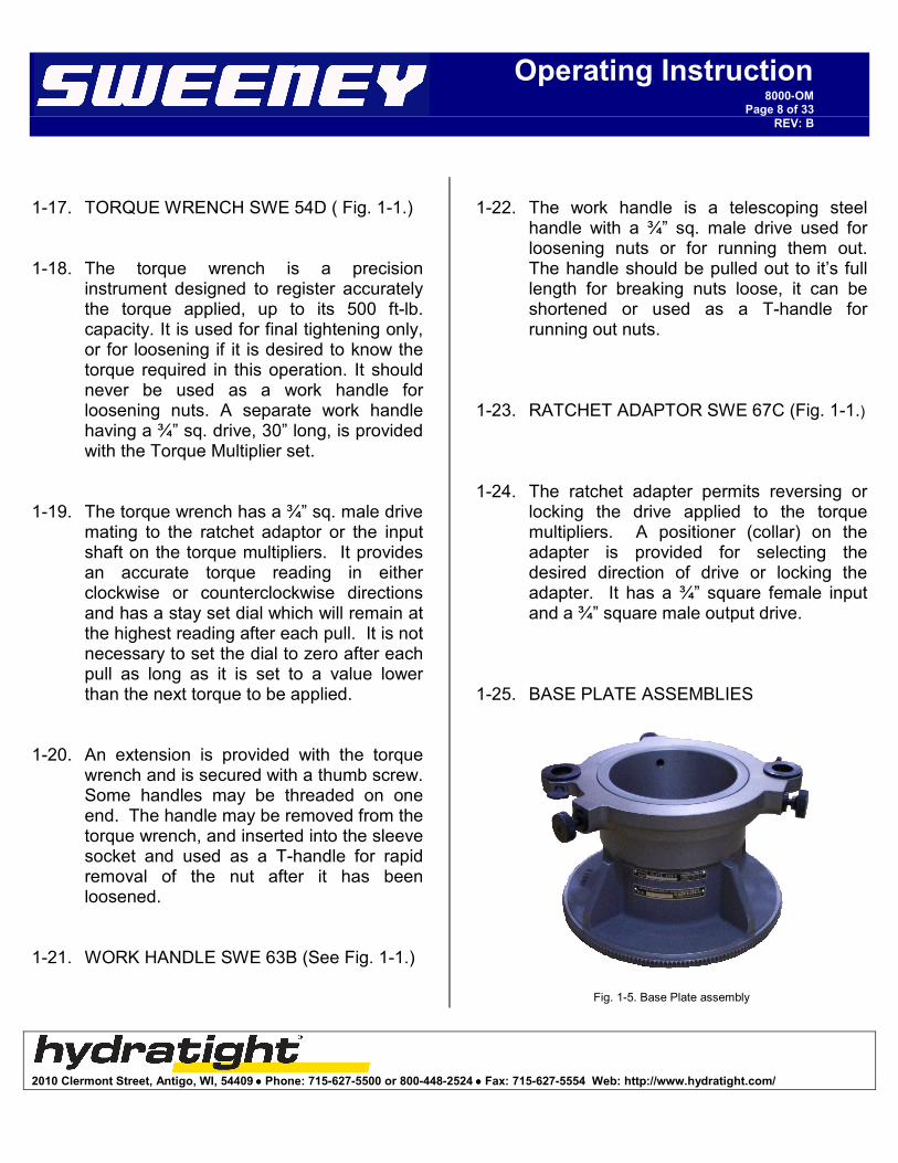
1-25. BASE PLATE ASSEMBLIES
Fig. 1-5. Base Plate assembly

2010 Clermont Street, Antigo, WI, 54409 •••• Phone: 715-627-5500 or 800-448-2524 •••• Fax: 715-627-5554 Web: http://www.hydratight.com/
Operating Instruction8000-OM
Page 9 of 33
REV: B
1-26. The base plate assemblies consist of a
base plate and retainer. Fig. 1-1 illustrates a typical base plate and retainer assembled to a lift assembly. The base plates are heat treated aluminum alloy castings specifically designed for attachment to a particular model propeller. The retainer locks the lift assembly to the base plate with two spring loaded plungers and one threaded plunger.
1-27. SLEEVE SOCKETS (See Fig. 1-1.)
1-28. The sleeve sockets are long steel tubes
adapted on one end to engage the propeller-retaining nut and externally splined on the other end to mesh with the Torque Multiplier output gear spline. A handle is provided inside the socket as an aid in inserting the socket into the Torque Multiplier. After insertion, the handle may be folded to permit visual alignment of the socket with the propeller-retaining nut. Holes provided in the outer end of the socket permit the insertion of the torque wrench handle for rapid removal of the nut after loosening.
1-29. LIFT ASSEMBLIES (See Fig. 1-1.)
1-30. The lift assemblies consist of a yoke
assembly, two C-hooks, a spreader bar and a safety cable, and provide a method for lifting and handling propellers during
removal or installation. 1-31. The lower ends of the C-hooks are
attached to the outer ends of the yoke assembly with a pivot connection and are secured at the upper ends to the spreader bar with pins, which are free to turn in the C-hooks. A spring loaded lock plunger in the right-hand C-hook is provided to release the lock plunger so that the propeller may be swung into another position. A safety cable is attached between the spreader bar and yoke assembly as an extra safety precaution.
1-32. The yoke assembly is so designed that a line between the pivot points at their outer ends passes near the center of gravity of the propeller. Thus, when the propeller is lifted with a crane hooked to the spreader bar, and the lock plunger is released, one man can easily tip the propeller to the most convenient position. The three positions in which the mechanism will lock are: propeller vertical and one blade down, propeller horizontal for carrying or installing on a vertical stub shaft, and one blade up for installing the propeller on a dolly.
1-33. RETAINER NUTS (See Fig. 1-5.)
1-34. The retainer nuts are threaded steel rings with holes provided for a spanner wrench. They are used for attaching base plates to the propeller hub on Hamilton Standard Propellers.

2010 Clermont Street, Antigo, WI, 54409 •••• Phone: 715-627-5500 or 800-448-2524 •••• Fax: 715-627-5554 Web: http://www.hydratight.com/
Operating Instruction8000-OM
Page 10 of 33
REV: B
1-35. SPANNER WRENCHES (See Fig. 1-6.)
Fig. 1-6. retainer nut, hub adapter, and spanner wrench.
1-36. The spanner wrenches are pin-type wrenches designed for use with the retainer nuts.
1-37. HUB ADAPTERS (See Fig. 1-6)
1-38. The hub adapters are steel rings designed to thread into the base plate and fit into the bore on Aeroproducts propellers.
1-39. CHESTS (See Fig. 1-7.)
Fig. 1-7. Storage chests.
1-40. The chests are of heavy gage steel for holding the various components of propeller or engine Torque Multiplier sets. For propeller sets the (-1) chest holds the lift assembly, and the (-2) chest holds all of the components necessary for torquing the propeller retaining nut. The engine chest holds all of the components necessary for torquing the engine thrust nut.
1-41. ANCHOR PLATES (See Fig. 1-2.)
1-42. The anchor plates are designed to support the Torque Multiplier on various model engine shafts when removing or installing engine thrust bearing nuts. Anchor plates are provided in two lengths, short and long. Short anchor plates are used on engines when the brush housing is removed and long anchor plates are used when it is installed. The anchor plates are internally splined to mate with the engine shaft. The torque multiplier is secured to the anchor plate with two thumbscrews. The torque wrench handle may be inserted at one end of the anchor plate to provide additional support when removing especially tight nuts.
1-43. THRUST NUT ASSEMBLY (See Fig. 1-2.)
1-44. The thrust nut socket assemblies are adapted on one end to engage the engine thrust bearing nut and externally splined on the other end to mesh with the torque multiplier output gear spline. Thrust nut sockets are provided in two lengths, short and long. Short sockets are used on engines when the brush housing is removed and long sockets are used when it is installed.

2010 Clermont Street, Antigo, WI, 54409 •••• Phone: 715-627-5500 or 800-448-2524 •••• Fax: 715-627-5554 Web: http://www.hydratight.com/
Operating Instruction8000-OM
Page 11 of 33
REV: B
1-45. TORQUE MULTIPLIER SET PROPELLER APPLICATIONS
1-46. Table 1 identifies the applicable torque multiplier set to be used with various model propellers. Propeller models are listed by manufacturer and part number.
1-47. Table 2 identifies the components, which comprise the various Torque Multiplier sets.
1-48. TORQUE MULTIPLIER COMPONENTS FOR ENGINE APPLICATIONS
1-49. Table 3 identifies the applicable torque multiplier components to be used with various model engines. The thrust bearing nut sockets are useable only with a particular design nut, which is identified by part number in the figure.
Fig. 1-8. SWE 8200 on retainer.
2010 Clermont Street, Antigo, WI, 54409 •••• Phone: 715-627-5500 or 800-448-2524 •••• Fax: 715-627-5554 Web: http://www.hydratight.com/
Operating Instruction8000-OM
Page 12 of 33
REV: B
SECTION II OPERATION INSTRUCTIONS
2. INTRODUCTION
2-1. This section contains instructions for propeller removal and installation using the applicable Torque Multiplier set. Instructions are also included for removal and installation of engine thrust bearing nuts. Procedures for removal and installation of propeller or thrust bearing nuts are almost identical with only minor differences. These differences are covered as applicable in the following paragraphs. Refer to tables 1 through 4 to determine the correct Torque Multiplier set and/or components for use with a particular model propeller or engine.
2-2. PROPELLERS, GENERAL
2-3. The Torque Multiplier set for propellers may be used on Curtiss, Hamilton-Standard, Aeroproducts, DeHavilland, and Rotol propellers. Each type of propeller may be removed or installed using the applicable lift assembly, base plate assembly, and adapters.
2-4. Remove all components of the Torque Multiplier set from the chest(s) in which they are stored. Ensure all parts and components required are included (see table 2) and are not damaged to the point where they are unusable or are not safe to use.
2-5. Assemble the lift assembly as follows:
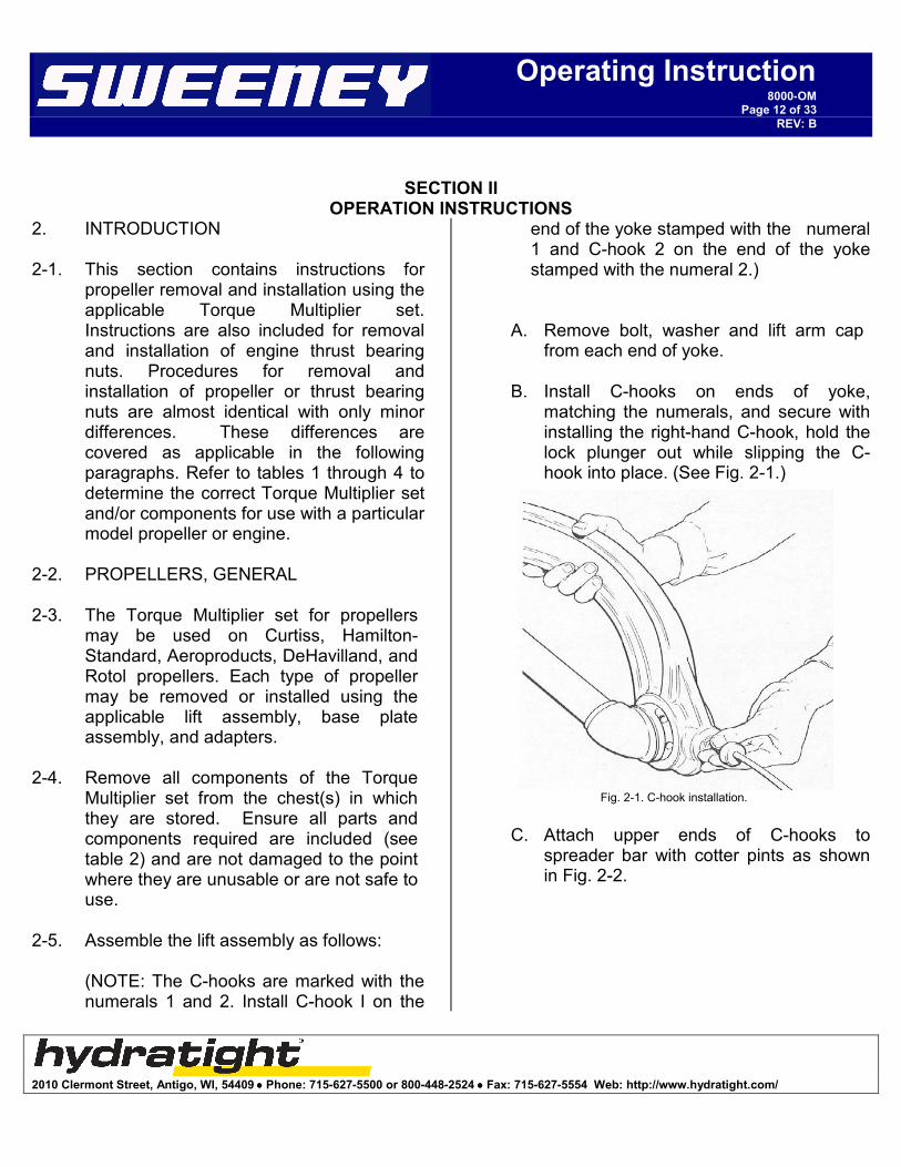
(NOTE: The C-hooks are marked with the numerals 1 and 2. Install C-hook I on the
end of the yoke stamped with the numeral 1 and C-hook 2 on the end of the yoke stamped with the numeral 2.)
A. Remove bolt, washer and lift arm cap from each end of yoke.
B. Install C-hooks on ends of yoke, matching the numerals, and secure with installing the right-hand C-hook, hold the lock plunger out while slipping the C-hook into place. (See Fig. 2-1.)
Fig. 2-1. C-hook installation.
C. Attach upper ends of C-hooks to
spreader bar with cotter pints as shown in Fig. 2-2.

2010 Clermont Street, Antigo, WI, 54409 •••• Phone: 715-627-5500 or 800-448-2524 •••• Fax: 715-627-5554 Web: http://www.hydratight.com/
Operating Instruction8000-OM
Page 13 of 33
REV: B
Fig. 2-2. spreader bar installation.
D. Attach snap end of safety cable to
eye bolt in yoke. Secure other end of cable to spreader bar using bolt, nut, and cotter pin.
2-6. PROPELLER REMOVAL 2-7. Perform the following steps preparatory to
removing a propeller.
A. Rotate three-blade propeller so that one blade is down in a vertical position. Rotate four-blade propellers so that blades are 45 degrees from vertical.
B. Remove propeller spinner nose,
power dome, and air inlets and outlets as necessary to expose the retaining nut.
C. Remove any locking assemblies on
the retaining nut.
2-8. BASE PLATE INSTALLATION 2-9. Install base plates on propellers as follows:
A. Curtiss Propellers- Remove bolts corresponding to mounting holes in base plate and any other protruding bolts which would prevent proper seating of the base plate on the propeller hub. The base plate for C-735SP propellers is installed using nine AN75-15 bolts and AN960-516 washers. The base plates for other Curtiss propellers are installed using the power dome bolts.
B. Hamilton-Standard and DeHavilland
Propellers- Remove dome retaining nuts and dome if not previously accomplished. Install base plate over locating dowels in propeller hub. Secure base plate to hub with retainer nut and tighten using spanner wrench.
C. Aeroproducts Propellers Base
plates for these propellers together with the applicable hub adapters and lift assemblies are useable on all Aeroproducts Propellers. The base plates are yoke shaped to fit over the blade hubs and are clamped in place. Install these base plates as follows: Select the applicable hub adapter, install in base plate from the rear and tighten with spanner wrench. Back knurled lock screws out of jaws rearward into slots in base plate arms. Place base plate over hub so that adapter enters hub bore and the arms fit

2010 Clermont Street, Antigo, WI, 54409 •••• Phone: 715-627-5500 or 800-448-2524 •••• Fax: 715-627-5554 Web: http://www.hydratight.com/
Operating Instruction8000-OM
Page 14 of 33
REV: B
over two of the blade sockets. Push the jaws forward to engage the blade sockets and tighten the lower knurled lock screws.
(CAUTION: The jaws are not engaged unless the detent plunger knobs are bottomed against the jaw.)
Base plate SWE 8431D may be used as an alternate for SWE 8451B on A642 series propellers. Remove the 12 bolts attaching the front cover.
(CAUTION: Do not disturb the position of the master gear retaining plate when removing the cover. Attach base plate to hub using all (12) AN74-10A bolts provided with the base plate.)
D. Rotol Propellers- Similar to Hamilton
Standard and DeHavilland except a foot on base plate takes the torque reaction against a blade hub. A lift assembly is not provided for use with Rotol propellers.
E. Some propellers do not have a snap
ring behind the retaining nut in the hub, which normally breaks the propeller loose from the rear cone seat as the nut is loosened. In these cases, a special sleeve socket with a ring around one end is used to break the propeller loose. Install the socket in place, then install a special spanner nut into base plate and run-in until seated against ring on socket. Proceed with normal operation. As the retaining nut is loosened, it will bear against the ring and break the propeller loose.
(CAUTION: Secure the base plate firmly in position, as it carries he full weight of the propeller during lifting or moving operations.)
F. Remove the retainer from the base plate, if installed, by turning the threaded plunger out as far as possible, then pulling the spring loaded plungers outward and lifting the retainer simultaneously.
(NOTE: If the spring loaded plungers do not pull out readily, turn the knobs to break them loose from their tapered seats.)
2-10. LIFT ASSEMBLY INSTALLATION
2-11. Install lift assembly on base plate as follows:
(CAUTION: The yoke and base plate are machined to close tolerances and should be squared to avoid cocking when the yoke is being installed on the base plate.)
A. Attach crane hook to center of lift assembly spreader bar and pick up the lift assembly. Align the yoke of the lift assembly with the base plate, slide yoke over base plate and seat firmly against shoulder of base plate. (See Fig. 2-3.)

2010 Clermont Street, Antigo, WI, 54409 •••• Phone: 715-627-5500 or 800-448-2524 •••• Fax: 715-627-5554 Web: http://www.hydratight.com/
Operating Instruction8000-OM
Page 15 of 33
REV: B
Fig. 2-3 attaching base plate to lift.
B. Pull spring-loaded plungers outward
and install retainer on base plate. Secure in place by tightening threaded plunger. (See Fig. 2-4.) Fig. 2-5 illustrates a typical base plate lift assembly installed on a propeller.
2-12. PROPELLER RETAINING NUT REMOVAL
2-13. Remove the propeller retaining nut as follows:
A. Install the Torque Multiplier in place on the base plate retainer, engaging the pins on rear of Torque Multiplier housing in corresponding holes in retainer. Secure the Torque Multiplier in place on the retainer with the thumbscrews. (See Fig. 2-6.)
Fig. 2-4 installing retainer on base plate.
Fig. 2-5. propeller supported by lift assembly
B. Select the applicable sleeve socket and insert through the Torque Multiplier output gear splines as shown in Fig. 2-7. If necessary, rotate the Torque Multiplier output gear using the knurled collar on the input drive to align the

2010 Clermont Street, Antigo, WI, 54409 •••• Phone: 715-627-5500 or 800-448-2524 •••• Fax: 715-627-5554 Web: http://www.hydratight.com/
Operating Instruction8000-OM
Page 16 of 33
REV: B
socket with the propeller-retaining nut. Ensure that the socket properly engages the retaining nut to the maximum extent.
(NOTE: On some propellers it may be necessary to install the sleeve socket before installing the Torque Multiplier)
C. Engage ratchet adapter on Torque Multiplier input drive (shown in place in Fig. 2-8). Engage work handle in ratchet adapter.
(CAUTION: Do not use torque wrench for loosening nuts.)
D. Break the retaining nut loose in a counterclockwise direction as shown in Fig. 2-9. Run nut out several turns and unseat propeller hub from rear cone.
(NOTE: If the retaining nut is especially tight and cannot be broken loose as described above, Torque Multiplier SWE 8202A may be used in conjunction with Torque Multiplier SWE 8200 to provide the necessary increase in torque output. Perform applicable steps of paragraph 2-19.)
Fig. 2-6. Installing torque multiplier.
Fig. 2-7. Installing sleeve socket
E. Remove work handle and insert handle from torque wrench through holes in sleeve socket and complete the removal of retaining nut. (See Fig. 2-9.)
F. Remove sleeve socket and Torque Multiplier.
G. Take up weight of propeller with crane and carefully swing the propeller free of the propeller shaft. (See Fig. 2-10.)

2010 Clermont Street, Antigo, WI, 54409 •••• Phone: 715-627-5500 or 800-448-2524 •••• Fax: 715-627-5554 Web: http://www.hydratight.com/
Operating Instruction8000-OM
Page 17 of 33
REV: B
2-14. PROPELLER TRANSPORTATION
2-15. Transport the propeller or install on dolly as follows:
A. If the propeller is to be transported by the crane for any appreciable distance, it should be carried in a vertical position.
B. To place the propeller in a horizontal position, pull the release cable to unlock the yoke and rotate the down blade upwards to the horizontal position. (See Fig. 2-11.) At this point the yoke will lock in place. This same procedure is used for installing the propeller on a vertical shaft for overhaul.
Fig. 2-8. Breaking nut loose with 63B
Fig. 2-9. Use of handle to run nut out
(NOTE: It may be necessary to wiggle the blade while pulling on the release cable to effect release of the lock plunger when it is under load.)
C. To install the propeller on its transporting dolly, release the lock, lift the down blade as the propeller is lowered by the crane and continue past the horizontal position, rotating the propeller about the lift arm pivots until it is in the position shown in Fig. 2-12. The yoke will lock at the proper angle with one blade up for propeller installation on the dolly

2010 Clermont Street, Antigo, WI, 54409 •••• Phone: 715-627-5500 or 800-448-2524 •••• Fax: 715-627-5554 Web: http://www.hydratight.com/
Operating Instruction8000-OM
Page 18 of 33
REV: B
Fig. 2-10. Propeller in vertical position
Fig. 2-11. Carrying Propeller in Horizontal Position
D. Remove lift assembly and base plate from propeller hub.
2-16. PROPELLER INSTALLATION
2-17. Procedures for propeller installation are essentially the reverse of those for removal. The following steps describe the normal method of propeller installation.
A. If required, remove all components of the Torque Multiplier set from the storage chest. Ensure no parts are missing or damaged.
B. Assemble the lift assembly in accordance with paragraph 2-5, if required.
C. Install the applicable base plate on the propeller in accordance with paragraph 2-8.
D. Install the lift assembly on the base plate in accordance with paragraph 2-10. If the propeller is on the transporting dolly, make certain the safety cable eye bolt on the yoke is on the opposite side from the up blade and that the open side of the C-hooks face away from the up blade. (See Fig. 2-12.)
Fig. 2-12.

2010 Clermont Street, Antigo, WI, 54409 •••• Phone: 715-627-5500 or 800-448-2524 •••• Fax: 715-627-5554 Web: http://www.hydratight.com/
Operating Instruction8000-OM
Page 19 of 33
REV: B
E. Attach crane hook to spreader bar and lift propeller. Unlock the yoke and rotate the propeller about the lift arm pivots until it is in a vertical position with one blade down. (See Fig. 2-10.)
F. Ensure all necessary preparations have been made on propeller shaft and related parts. Carefully install the propeller on the shaft, ensuring that the part of the hub which is free to rotate is properly aligned with the shaft and related parts.
G. Look into the space around the propeller shaft and ensure all parts are properly aligned and that the threads on the shaft can be engaged by the retaining nut.
H. Install Torque Multiplier, inserting pins in rear of housing into mating holes in base plate retainer and secure in place with thumbscrews.
I. Insert the applicable sleeve socket through the Torque Multiplier, engaging the retaining nut and Torque Multiplier output gear using knurled collar on input with retaining nut and output gear splines.
J. Insert handle from torque wrench in sleeve socket and tighten retaining nut until it is snug.
(NOTE: If the maximum input torque of Torque Multiplier SWE 8200 is marginal or less than that required for the particular installation, Torque Multiplier SWE 8202 may be used in conjunction with SWE 8200 to provide the necessary increase in torque output. Perform applicable steps of paragraph 1-12 and steps N and O of this paragraph.)
K. Engage ratchet adapter on Torque Multiplier input drive and torque wrench on adapter. Insert handle in torque wrench. (See Fig. 2-13.)
Fig. 2-13. Torquing nut with 54D
L. When tightening right-hand or
loosening left-hand nuts, rotate knob in center or dial cover on torque wrench in a counterclockwise direction until dial rests against stop. Then rotate dial cover, positioning red line over 0 on dial scale. When tightening left-hand or loosening right-hand nuts, rotate knob in a clockwise direction until dial rests against stop, then rotate dial cover until red line is over 0 on scale.
M. Refer to torque conversion table on top of Torque Multiplier housing and using the rated torque value for the nut, determine the torque which must be applied to the input drive of the Torque Multiplier to obtain that rated torque at the Torque Multiplier output. Observing

2010 Clermont Street, Antigo, WI, 54409 •••• Phone: 715-627-5500 or 800-448-2524 •••• Fax: 715-627-5554 Web: http://www.hydratight.com/
Operating Instruction8000-OM
Page 20 of 33
REV: B
the dial on the torque wrench, pull the torque wrench until the input torque (as determined from table) is applied at the Torque Multiplier input as indicated on the dial scale.
(NOTE: When installing propellers using a retaining nut with internal threads and external splines, look into the sleeve socket while the nut is being tightened and not when one of the locking holes in the propeller shaft aligns with a slot in the nut. Then install the spring-loaded lock and turn down very slowly until the snap of the lock engaging in place is heard. The torque at this point should not be less than the specified minimum value.)
N. Remove lift assembly, base plate and accessories from hub.
O. Reinstall power dome or spinner nose and any other parts previously removed.
2-18. ENGINES, GENERAL
2-19. The Torque Multiplier components for engines may be used on the R-985, R-1300, R-1340, R-1820, R-1830, R2000, R-2600, R-2800, R-3350, R4360, 501D13, T-53, T-55 and T-56 model engines.
2-20. Refer to Table 3 to determine the correct torque multiplier components for use with the particular model engine. Remove all components of the torque multiplier set from the chest in which they are stored. Ensure all parts and components are included and are not damaged to the
point where they are unusable.
2-21. Thrust Bearing Nut Removal
2-22. Remove engine thrust bearing nuts as follows:
A. Install the thrust nut socket over the engine shaft and engage the thrust nut as shown in Fig. 2-14.
Fig. 2-14. Engine shaft with thrust nut socket installed.
B. Assemble anchor plate to torque
multiplier and secure in place with thumbscrews.
C. Install assembled Torque Multiplier and anchor plate on shaft with torque multiplier toward engine. Engage Torque Multiplier output gear splines with splines on socket and splines on anchor plate with splines on shaft. If necessary, use the knurled collar on the torque multiplier input drive (cover side) and rotate the output gear to align the socket and output gear splines.

2010 Clermont Street, Antigo, WI, 54409 •••• Phone: 715-627-5500 or 800-448-2524 •••• Fax: 715-627-5554 Web: http://www.hydratight.com/
Operating Instruction8000-OM
Page 21 of 33
REV: B
D. Engage ratchet adapter and work handle on torque multiplier input drive. (See Fig. 4-15.) If it is desirable to determine loosening torque, the torque wrench may be used in place of the work handle. Set dial of torque wrench for loosening right-hand or left-hand nuts in accordance with paragraph 4-13, step L. Refer to conversion table on Torque Multiplier to convert indicated breakaway torque to actual torque at nut.
(NOTE: When removing a tight thrust nut, the torque wrench handle may be inserted in one end of anchor plate. The handle is then used to prevent the engine shaft from turning while the nut is loosened. See Fig. 2-15.
2-15. Removing Tight Thrust Nut
If the thrust bearing nut is especially tight and cannot be broken loose as described above, Torque Multiplier SWE 8202 may be used in conjunction with Torque Multiplier SWE 8200 to provide the necessary increase on torque output. Perform applicable steps of paragraph 1-12.)
E. Break nut loose, remove work handle or torque wrench, ratchet adapter, anchor plate, Torque Multiplier and socket. Remove nut.
2-23. Thrust Bearing Nut Installation 2-24. Install engine thrust bearing nuts as
follows: A. Install nut on engine shaft and tighten
finger tight.
B. Install thrust nut socket, Torque Multiplier and anchor plate in accordance with steps A through D, paragraph 4-17.
(NOTE: If the maximum output torque of Torque Multiplier SWE 8200 is marginal or less than that required for the particular installation, Torque Multiplier SWE 8202 may be used in conjunction with SWE 8200 to provide the necessary increase in torque output. Perform applicable steps of paragraph 2-21 and step F or this paragraph.)
C. Engage ratchet adapter and torque wrench on Torque Multiplier input drive. (See Fig. 2-16.)
D. Set dial of torque wrench for tightening right-hand or left-hand nuts in accordance with step A, paragraph 1-17.

2010 Clermont Street, Antigo, WI, 54409 •••• Phone: 715-627-5500 or 800-448-2524 •••• Fax: 715-627-5554 Web: http://www.hydratight.com/
Operating Instruction8000-OM
Page 22 of 33
REV: B
Fig. 2-16. Torquing thrust nut.
E. Torque thrust nut in accordance with
step M, paragraph 4-13.
F. Remove torque wrench, ratchet, adapter, anchor plate, Torque Multiplier and socket. Multiplier input drive. (See Fig. 4-16.)
2-25. Tight Propeller Retaining or Engine Thrust Bearing Nut Removal or Installation. Excessively tight or seized propeller retaining nuts or engine thrust bearing nuts
may be removed as described below. These procedures may also be used for installation of nuts where the output torque or Torque Multipliers SWE 8200 is marginal or less than required.
A. Install Torque Multiplier SWE 8202 on
Torque Multiplier SWE 8200 as shown in Fig, 1-3, engaging the output drive of SWE 8202 with the input of SWE 8200. The anchoring slot in SWE 8202 must fit over the boss between the input and output of SWE 8200.
B. Set Air Pressure Valve at 90-psi (50 cfm) and directional control to counterclockwise. Hold air control down until nut breaks loose, then continue to operate to back nut off shaft.
C. For tightening nut on shaft, set Air Pressure Valve at recommended psi for torque required (see OI-8202 for complete description). Use SWE 54D for final torque input reading.

2010 Clermont Street, Antigo, WI, 54409 •••• Phone: 715-627-5500 or 800-448-2524 •••• Fax: 715-627-5554 Web: http://www.hydratight.com/
Operating Instruction8000-OM
Page 23 of 33
REV: B
SECTION III. PERIODIC INSPECTION, MAINTENANCE AND LUBRICATION
3. INTRODUCTION E. Fraying- Replace cables if strands are 3-1. This section provides instructions for periodic inspection, maintenance and 3-2. INSPECTION 3-3. Carefully inspect the Torque Multiplier set
components each time they are used. Check each component as it is removed from its storage chest and before it is replaced.
3-4. Inspect work handle, ratchet adapter,
slings, base plate assemblies, retainer nuts, spanner wrenches, hub adapters, sleeve sockets, anchor plates and thrust nut sockets for the following and repair to the extent indicated.
A. Cracks - Do not attempt repair of
cracks. Replace the part. B. Scratches - Remove sharp edges with stone or fine cut file.
C. Burrs - Remove with stone or fine cut file.
D. Galling or Cross Threading – Dress
cross-threaded or galled threads with fine file, thread chaser or appropriate size tap or die. Dress galling or other damage to splines with stone or fine cut file. If damaged threads or splines cannot be made to engage freely, replace the part.
E. Fraying – Replace cables if strands are frayed or broken.
3-5. TORQUE MULTIPLIERS 3-6. Inspect housing and cover for cracks or
other damage, evidence of leaking lubricant, or damage to output gear spline. Rotate knurled collar on input drive of SWE 8200 Torque Multiplier and check gear train for freedom of movement. Return the torque multiplier for overhaul when there is evidence of leakage from dust seals, damaged splines which cannot be repaired with a fine cut file, evidence of binding in the gear train, or cracks in cover or housing. Inspect the gear train for wear, galling, chipped or broken gear teeth, each time the cover is removed for lubrication.
3-7. LIFT ASSEMBLY 3-8. Inspect the spreader bar, C-hooks and
yoke assembly for cracks or other damage. Check that lock plunger moves freely and that there is no binding at the pivot points. Inspect safety cable.
3-9. TORQUE WRENCH 3-10. Rotate dial and cover of torque wrench and
check for freedom of movement. 3-11. MAINTENANCE, DISASSEMBLY 3-12. Lift Assembly. Disassemble the lift

2010 Clermont Street, Antigo, WI, 54409 •••• Phone: 715-627-5500 or 800-448-2524 •••• Fax: 715-627-5554 Web: http://www.hydratight.com/
Operating Instruction8000-OM
Page 24 of 33
REV: B
assembly as follows: A. Unsnap safety cable from eye bolt in yoke; remove cotter pin, nut and bolt securing cable to spreader bar. Remove cable.
B. Remove Cotter pins from spreader bar pins, remove spreader bar pins from C-hooks, and remove spreader bar.
C. Remove bolt, lock washer and cap securing C-hooks to yoke. Remove left-hand C-hook. Pull lock cap outward to release lock plunger and remove right-hand C-hook from yoke.
3-13. Torque Multipliers
3-14. Torque Multipliers must not be disassembled except as required for lubrication (see paragraph 5-22).
3-15. Cleaning. Clean all parts in solvent (Military Specification MIL-S-18718 or equivalent) as required.
3-16. Repair
3-17. Repair of most Torque Multiplier set components is limited to removal of sharp edges caused by minor scratches, nicks, burrs or other damage. As most components are subject to a high degree of stress when in use, no attempt should be made to repair cracks or any damage, which has seriously weakened the structural integrity of the part. Minor damage to threads or splines may be repaired but the part should be replaced if difficulty is encountered in engaging mating
parts after such repair.
3-18. Lift Assembly Lock Release Cable. To replace a broken or damaged lock release cable, loosen lock nut and remove lock assembly from right-hand C-hook. Pull cap out of recess in lock nut and drive out brass pin securing plunger in cap. Unscrew plunger from cap and remove spring. Insert new cable (3/32” diameter, 7x7 aircraft cable, 42-1/2” long) through rubber sheath, install cap on one end and ball on the other. Swage a single shank ball-type cable terminal on each end of the cable. Reassemble the lock assembly using a new brass pin. Rivet each end of the pin and grind or file flush. Install lock assembly in right-hand C-hook.
3-19. MAINTENANCE, ASSEMBLY
3-20. Lift Assembly. The parts of the lift assembly may be placed in their storage chest or assembled in accordance with paragraph 4-5 as desired. If parts are to be stored, temporarily secure spreader bar pins in spreader bar using new cotter pins, assemble safety cable bolt and nut to spreader bar or cable end using new cotter pin, and install C-hook bolts, lock washers and cap in place on yoke to prevent loss. At time of assembly, place a few drops of light oil on spreader bar pins and on yoke pivots.
3-21. Testing. Testing after re-assembly is not required.
3-22. LUBRICATION 3-23. Lift Assembly. Apply a light oil to the lock

2010 Clermont Street, Antigo, WI, 54409 •••• Phone: 715-627-5500 or 800-448-2524 •••• Fax: 715-627-5554 Web: http://www.hydratight.com/
Operating Instruction8000-OM
Page 25 of 33
REV: B
plunger and the pivot points of the lift assembly if there is evidence of binding.
3-24. Care should be exercised when using the
tool to protect it from external damage and corrosive environments. Inspect the torque multiplier and related tools at each use for cracks in the housing castings. These parts are subject to a high degree of stress when in use; no attempt should be made to repair cracks or any damage that has seriously weakened the structural integrity of the part. Contact the factory for
replacement parts. A fine cut file or stone may remove minor scratches, burrs, or nicks. Disassembly and inspection of internal parts is recommended once a year. Worn or damaged parts should be replaced with original factory parts only. Lubricate with Premium #2 Lithium Base, Ball and Roller Bearing Grease. Each unit is certified for accuracy at the factory before shipment. Recertification is advised after disassembly and inspection or parts replacement (if required).
SECTION IV.
TROUBLE SHOOTING
4. INTRODUCTION 4-1. This section provides instructions for
trouble shooting the torque multiplier sets. 4-2. TROUBLE SHOOTING 4-3. The following issues are ones commonly
encountered with lift sets and multipliers. 4-4. Binding in the multiplier or multiplier will not
turn freely. The gear train is most likely damaged and the tool needs to be returned to a service center for overhaul.
4-5. Sleeve socket will not fit torque multiplier;
in this case the splines most likely have burrs on them. In this case the burrs can be removed with a file. If the socket still does not fit, the socket and tool should be returned to a service center for overhaul.
4-6. lift assembly will not pivot properly, or
binds. This is caused by a lack of lubrication, lubricate pivots and lock assembly with light machine oil.
4-7 lift will not lock in position. Check the lock
pin assembly for damage and a bent lock pin. If the pin is bent no attempt to straighten it should be made. A replacement pin should be purchased.

2010 Clermont Street, Antigo, WI, 54409 •••• Phone: 715-627-5500 or 800-448-2524 •••• Fax: 715-627-5554 Web: http://www.hydratight.com/
Operating Instruction8000-OM
Page 26 of 33
REV: B
CALIBRATION NOTE The maximum recommended calibration period for all torque multipliers is twelve (12) months. However, depending on the amount the tools is used the calibration period should be reduced to a shorter interval to insure the accuracy of the tool. Please contact us if you have other questions or concerns.

2010 Clermont Street, Antigo, WI, 54409 •••• Phone: 715-627-5500 or 800-448-2524 •••• Fax: 715-627-5554 Web: http://www.hydratight.com/
Operating Instruction8000-OM
Page 27 of 33
REV: B

2010 Clermont Street, Antigo, WI, 54409 •••• Phone: 715-627-5500 or 800-448-2524 •••• Fax: 715-627-5554 Web: http://www.hydratight.com/
Operating Instruction8000-OM
Page 28 of 33
REV: B

2010 Clermont Street, Antigo, WI, 54409 •••• Phone: 715-627-5500 or 800-448-2524 •••• Fax: 715-627-5554 Web: http://www.hydratight.com/
Operating Instruction8000-OM
Page 29 of 33
REV: B

2010 Clermont Street, Antigo, WI, 54409 •••• Phone: 715-627-5500 or 800-448-2524 •••• Fax: 715-627-5554 Web: http://www.hydratight.com/
Operating Instruction8000-OM
Page 30 of 33
REV: B

2010 Clermont Street, Antigo, WI, 54409 •••• Phone: 715-627-5500 or 800-448-2524 •••• Fax: 715-627-5554 Web: http://www.hydratight.com/
Operating Instruction8000-OM
Page 31 of 33
REV: B

2010 Clermont Street, Antigo, WI, 54409 •••• Phone: 715-627
627-5500 or 800-448-2524 •••• Fax: 715-627-5554 Web: http://www.hydratight.com/
Operating Instruction
http://www.hydratight.com/
Operating Instruction8000-OM
Page 32 of 33
REV: B

2010 Clermont Street, Antigo, WI, 54409 •••• Phone: 715-627
627-5500 or 800-448-2524 •••• Fax: 715-627-5554 Web: http://www.hydratight.com/
Operating Instruction
http://www.hydratight.com/
Operating Instruction8000-OM
Page 33 of 33
REV: B