operating manual - cbs products
TRANSCRIPT

CBS Products (KT), Ltd, Pillings Road, Oakham, Rutland, LE15 6QF, Tel: +44(0) 1572 723 665 Fax: +44(0) 1572 756 009 E-mail: [email protected] Website: www.cbsproducts.com
OPERATING MANUAL
C–1300–05-T (BREEZE)
Serial Numbers 0377 Onwards
CABLE BLOWING MACHINE
Copyright 2018 by CBS Products (KT), Limited All rights reserved. No part of this publication may be copied, reproduced or transmitted in any form whatsoever without the written permission of CBS Products (KT), Ltd.

Page 2 of 42
REVISION HISTORY:
Rev.no Date Details Author
01 25.01.18 Original issue A. Sibun

Page 3 of 42
CONTENTS
1.0 Safety Instructions
2.0 Critical Points
3.0 General Description
4.0 Specification
5.0 Operating procedures
6.0 Maintenance
7.0 Procedure for changing inserts in the tube clamp
8.0 Procedure for changing inserts in the air box
9.0 Procedure for changing inserts in the infeed guide
10.0 Procedure for re-positioning the measuring system fixed roller
11.0 Procedure for replacing the air box housing seal
12.0 Procedure for changing the air box infeed guide
13.0 Procedure for changing the drive rollers
14.0 Monthly Service – check list
15.0 Service History Record
16.0 Tube integrity and Lubrication
17.0 Recommended Spares List
APPENDICES
Appendix 1 Cable and tube insert selection chart. Appendix 2 Recommended torque control potentiometer settings Appendix 3 Counter/Ratemeter Programming Instructions

Page 4 of 42
1.0 SAFETY INSTRUCTIONS
THIS EQUIPMENT SHOULD BE USED ONLY BY PERSONNEL WHO HAVE BEEN GIVEN THE APPROPRIATE TRAINING, AND WHO ARE COMPETENT
TO USE IT. THESE INSTRUCTIONS ARE TO BE MADE AVAILABLE TO OPERATORS OF THIS EQUIPMENT AT ALL TIMES, FAILURE TO OBSERVE THESE SAFETY INSTRUCTIONS COULD RESULT IN SERIOUS PERSONAL INJURY AND/OR
PROPERTY DAMAGE.
WORK AREA AND GENERAL SAFETY 1. Read and understand the operation and maintenance manual supplied with this
equipment. Keep it in a convenient place for future reference.
2. Keep children and untrained personnel away from this equipment whilst in operation.
3. Keep all guards and safety devices in place. Do not operate this equipment with
guards removed or damaged.
4. Keep hands, feet and loose clothing away from moving parts, especially at cable entry
points.
5. Always stop the machine and isolate compressed air and electrical services to carry
out lubrication and servicing.
6. Check machine before starting for worn or damaged parts. Check for signs of loose
nuts and bolts etc.
7. If machine is left unattended, ensure that unauthorised use is prevented.
8. Never leave the machine unattended whilst in use.
9. Consider the use of safety barriers, especially when used in public places, observe all
statutory requirements for working environments.
10. Beware of pinch points involved with rotating components,
11. Beware of hot surfaces, machine uses compressed air.
12. When operating machine always wear appropriate safety clothing, ear defenders, eye
protection, hard hat, safety shoes and leather gloves, machine operates with
compressed air at up to 15 Bar.
13. Prior to installation ensure the tube route is connected properly.
14. Beware of exposed electrical contacts. Do not touch, or allow metal objects to come
into contact.
15. Machine may cause additional fire hazard if involved in an existing fire due to
compressed air.

Page 5 of 42
16. No personnel are to be in manholes or ducts when the Cable Blowing Machine is
being operated.
17. The machine must be operated on firm ground.
18. Stay clear of cables or lines under tension.
19. Stay clear of pressurised air line and tube.
20. Only use the machine for its intended purpose, do not use the roller drive without the
air chamber to push or to retrieve cable, blow air in the far end to help cable recovery.
21. Do not place cable drum too close to the Cable Blowing Machine.
22. Do not tamper with pressure relief valves or pressure reducing valves.
23. The compressed air supply must not be allowed to enter the air chamber or tube
before the rollers have been closed on to the cable. Do not turn the air on until a
reasonable length of cable (50m) has been installed into the tube.
24. Ensure the cable drum rotates freely on its stand, the cable should leave from the top
of the drum.
25. The cable should enter the machine in a clean and dry condition. In damp, dusty
atmospheres, the cable should be cleaned continuously as it enters the machine.
FAILURE TO DO SO MAY RESULT IN PERSONAL INJURY, AS THE CABLE COULD BE EJECTED FROM THE CABLE BLOWING MACHINE WITH HIGH FORCE AND VELOCITY. If the connecting plug on the power lead to the generator / (or supply) supplied with the Breeze machine is unsuitable and requires replacement, the new plug must be correctly connected observing the colour codes as below. IT IS THE RESPONSIBILITY OF THE USER TO ENSURE THAT THE CONNECTIONS MEET THE ELECTRICAL REGULATIONS FOR THE RELEVANT COUNTRY.
BROWN (LIVE)
BLUE (NEUTRAL)
YELLOW AND GREEN (EARTH)

Page 6 of 42
GENERAL PNEUMATIC SAFETY INSTRUCTIONS The CBS Fibre Optical Cable Blowing Machine is a pneumatic device, using pressurised air to project cable at high velocities. Please observe the following precautions when operating the Cable Blowing Machine:- Compressed air can cause flying debris. This could cause personal injury. Always wear personal protective equipment. Ensure no personnel are in the manhole at the far end of the cable run. Severe personal injury may result. Never open the air chamber when pressurised. Only authorised, fully trained personnel should operate the air compressor.
GENERAL ELECTRICAL SAFETY INSTRUCTIONS The machine has electronic and electrical power and control circuits. Electric shock hazards exist that could result in severe personal injury. Observe the following precautions to avoid electrical hazards: Do not operate in water. Do not expose the machine to rain. Do not remove cover of electronic control assembly. There are no user serviceable parts inside. Refer servicing to qualified service personnel.

Page 7 of 42
2.0 CRITICAL POINTS THAT DRAMATICALLY AFFECT THE OPERATION OF THE CABLE BLOWING MACHINE
• PRESSURE ON THE CABLE (POSITION OF THE CLOSE ARM ASSY) SHOULD BE SET AS PER THE INSTRUCTIONS
• ROLLERS TO BE CLOSED AT ALL TIMES WHEN CABLE IS INSTALLED INTO MACHINE.
• CORD SEALS IN AIR CHAMBER CORRECTLY FITTED TO PROVIDE GOOD SEALING.
• CORRECT CABLE SEAL FITTED.
• TUBE FULLY CONNECTED AND PRESSURE-TESTED.
• TUBE CONNECTING FITTINGS ARE SUITABLE FOR OPERATING AT 15 BAR AIR PRESSURE.
• TUBE CLAMP SECURELY TIGHTENED.
• COMPRESSOR CAPACITY 15 BAR AND SUITABLE FOR SIZE OF TUBE BEING USED.
• CABLE DRUM MUST BE LOCATED DIRECTLY BEHIND AND IN LINE WITH THE BLOWING MACHINE.
• AIR CHAMBER, DRIVE ROLLERS, CABLE GUIDES, MUST BE CLEAN AND FREE FROM DEBRIS, SLUDGE, DIRT, WATER AND LUBRICANT.
• THE CABLE MUST BE HAND GUIDED INTO THE BLOWING MACHINE THROUGH A DRY CLEAN CLOTH BY THE OPERATOR WEARING WORK GLOVES.
• ENSURE THE COMPRESSED AIR SUPPLY IS NOT APPLIED TO THE CABLE UNTIL APPROXIMATELY 50 METRES OF CABLE HAVE BEEN INSTALLED OR THE MOTOR BEGINS TO LABOUR.

Page 8 of 42
DISCLAIMER
CBS Products (KT), Ltd takes care in the design of its products to ensure that the cable is protected during installation. Due to the variety and different methods of cable manufacture the responsibility of checking the cable compatibility with the equipment lies with the operator. Therefore, CBS Products (KT), cannot accept liability for any damage to the cable.

Page 9 of 42
3.0 GENERAL DESCRIPTION The CBS Breeze machine is designed to install small diameter cable into underground tubes. The machine uses a DC motor and reduction gearing to drive a pair of compliant rollers (both rollers are driven). The rollers are covered with a compliant coating to prevent damage to the cable. A range of different coatings is available depending on the surface texture of the cable being installed. The rollers may be changed quickly using one simple tool. The pressure the rollers apply to the cable may be set between zero and maximum. During installation, the torque applied to the cable by the rollers can be adjusted to prevent the cable buckling and to prevent damage to the cable. A full range of accessories is available to allow the machine to handle a wide range of cables and tubes. This machine has the added function of high/low torque selection; this has been developed to give greater sensitivity when operating in the low torque region aiding the
installation of small cables (Ø<2.5mm, 0.01”). As pictured above, the machine may be placed on the ground or on a support to bring the cable to a suitable height. A separate reinforced transit housing is available, this will protect the machine from damage during transit and can be used as a support for the machine when being used to install cable.

Page 10 of 42
4.0 SPECIFICATION
Cable size: 1.5 to 8.0 0.06” to 0.315”
Tube size: (OD) 5 to 16 0.197” to 0.630”
Cable speed: 0-50m/min. 0-164 ft/min
Maximum pushing force: 16 Kg. 35 lb.
Maximum air pressure: 15 bar. 210 psi.
Power requirements: 115 or 230V ac 50/60 Hz Factory Set
Gripping force, (rollers onto cable): 1-40 Kg 1-88 lb.
Weight 23Kg approx. 50 lbs. approx.
Dimensions (ht x length x width) 250mmx390mmx270mm 10”x15 3/8” x10 5/8”

Page 11 of 42
5.0 OPERATING PROCEDURE
IT IS IMPERATIVE THAT ALL PERSONS USING, OPERATING OR MAINTAINING THIS CABLE BLOWING MACHINE:
• HAVE RECEIVED COMPREHENSIVE TRAINING IN THE USE OF THIS MACHINE.
• ARE COMPETENT TO USE IT,
• AUTHORISED TO USE IT AND
• HAVE READ AND UNDERSTOOD THIS MANUAL
• CBS PRODUCTS (KT) LTD. CANNOT BE HELD RESPONSIBLE FOR MISUSE OF THIS EQUIPMENT.
Set up for installing cable with the machine mounted above ground: Position the machine in line with the route of the duct. Position the cable drum behind the machine and in line with the machine. See sketch below (this shows a plan view of the recommended set up).
Ensure the machine is secure (either on its own stand or a separate suitable stand). Ensure the machine is fitted with the appropriate guides and collets to suit the cable being installed and tubes into which the cable is to be installed. (See Appendix 1 for details of interchangeable parts). To set the machine up to install cable it will be necessary to: Select the appropriate Torque setting for the cable being installed, if in doubt start with the low torque setting. Fit the tube into which the cable is to be installed into the air box and tube clamp. Fit the cable through the machine. Connect the air supply to the machine.
Breeze machine
Tube route
Cable drum

Page 12 of 42
Connect the electrical power input to the machine.
NOTE: DO NOT PRESS RST ON THE COUNTER WHILE POWERING UP THE MACHINE.
Fit the tube into which the cable is to be installed into the air box and tube clamp. It is recommended that a length of tube similar in size to the tube into which the cable is to be installed be fitted in the tube clamp. This length of tube may then be connected to the installed tube (the length of tube underground into which the cable is to be installed). Using a suitable connector. Slide a suitable size O ring over the end of the tube. Fit the tube into the end of the air box housing so that it protrudes approx. half way into the housing as shown in the sketch, position the O ring so that it sits against the seal face, as shown in the sketch.
Once the tube has been positioned, the tube clamp may be closed, the swing bolt swung down and the thumb nut tightened, the tube is now secure.
Cut and split a short length of tube to use as an infeed guide. This should be clamped in the infeed guide assembly 2. This short length of tube will act as a guide to feed the incoming cable into the measuring system and on into the infeed guide.

Page 13 of 42
Fit the cable through the machine.
Hold back the measuring wheel, so
that the pressure spring is compressed.
Raise the clear cover to expose the roller drive.
Move the close assembly. to the far right to fully open the rollers
Loosen the thumb nuts and retract the cable guide top plate.
Loosen the thumb nut and open the seal housing

Page 14 of 42
It is now possible to insert the cable in the machine. Pass the cable through the infeed guide assembly 2, on through the infeed guide assembly, through the gap between the drive rollers. Place the cable in the groove in the cable guide assembly (outfeed). Select the appropriate split cable seal (See Appendix 1) and position it around the cable, press the cable seal into the groove in the seal housing, simultaneously placing the cable in the cable seal guide and inserting the cable in the tube entry. The cable is now positioned in the machine.
Close the airbox. Reposition the cable guide outfeed top cover. Release the measuring wheel and allow it to rest on the cable. Close the transparent cover over the feed rollers. Close the drive roller assembly onto the cable as follows: The sketch shows the drive roller close thumbscrew slightly loosened. (The assembly is free to move). This thumbscrew is fixed to the clamp arm lever. The clamp arm lever controls the position of the roller assembly. As the clamp arm is moved around the quadrant the rollers move together and apart. When the clamp arm is furthest to the right, the gap between the rollers is at a maximum. And vice versa. When preparing the machine to insert the cable, the clamp arm is positioned at its furthest point to the right (rollers open). Once the cable has been positioned in the machine the rollers must be closed on the cable in order to drive the cable. (And to stop the cable being dragged back out of the machine by any tension in the cable).
Measuring wheel
Infeed guide assembly 2
Infeed guide assembly
Close assembly clamp lever

Page 15 of 42

Page 16 of 42
The amount of pressure on the cable can be varied simply by loosening the thumb nut, moving the clamp arm lever to the right or left; as required, and tightening the thumbscrew. As more experience is gained using the machine, the amount of compression required will become clear.
Note: An alternative method of setting the compression force is detailed in the note at the end of Appendix 2.
Connect the air supply to the machine.
The air inlet to the machine is male fitting for a quick release coupling. The air inlet to the machine must terminate in a suitable connector.
Connect the electrical supply to the machine. The electrical supply must terminate in an RS type 3-way cable connector. Adaptors are available to suit any required existing connector, speak to our sales department for full details and specification of connector. If the power supply lead supplied with the Breeze Cable Blowing Machine is unsuitable and requires to be changed refer to the safety instructions for further details.
NOTE: DO NOT PRESS RST ON THE COUNTER WHILE POWERING UP THE MACHINE. IT IS THE RESPONSIBILITY OF THE USER TO ENSURE THAT THE CONNECTIONS MEETS THE ELECTRICAL REGULATIONS FOR THE RELEVANT COUNTRY.

Page 17 of 42
The machine is now ready to start the cable installation.

Page 18 of 42
Set up for installing cable with the machine mounted below ground: The set up is similar to the set up for installing cable above ground, (described above) typically this type of installation is demanded for “series blowing” i.e. when a length of cable is already installed, and the limit of installation distance is reached. In such cases it is customary to couple a “series machine” sited down a manhole some distance from the point of main installation. This machine operates in conjunction with the machine sited at the main point of installation. The CBS Breeze machine is ideally suited to this type of operation, it may be coupled with a second machine to increase the distance a single cable can be installed without joins. The only difference between this set up, and the set up for installing cable with the machine above ground, is that there will be no drum stand carrying the cable drum. The cable will be exiting from one side of the manhole and blown into the tube at the other side of the manhole. The machine should be aligned with both the incoming cable and the outgoing tube path, both side to side and up and down.
NOTE: THE MACHINE MUST NOT BE SUBMERGED IN WATER.
If the hole is full of water it must be pumped out before placing the machine on the bottom of the hole.

Page 19 of 42
Installing cable. The machine is fitted with a range of controls to help the operator to install cable in the minimum time with the least risk of causing damage to the cable or tube. These controls are identified and their function is described below.
Torque control: This potentiometer controls the motor torque, turn this clockwise to increase the torque (pushing force) applied to the cable by the rollers. Turn counter clockwise to reduce the amount of torque (pushing force) applied to the cable by the rollers.
Speed control: This potentiometer controls the motor speed, turn this clockwise to increase the speed of the rollers (and the cable). Turn counter clockwise to reduce the speed.
Emergency stop: Pushing this red knob downwards will stop the rollers feeding the cable. This knob may be used to switch the machine off, whether or not there is a need to stop in an emergency. To release; twist the red knob counter-clockwise.
Speed / Distance Indicator
High/Low Torque Selector
Torque Control
Speed Control
Emergency Stop
Start

Page 20 of 42
Start: This switch “arms” the emergency stop circuit. If the emergency stop button is used to stop the machine (whether in an emergency or not) it will be necessary to depress this switch before the machine will run again. Whenever the power to the machine is disconnected and reconnected, it will be necessary to depress this switch before the machine will run.
Speed Distance indicator: This device will measure and display the distance travelled by the cable and also the speed at which the cable is travelling. To toggle between speed and distance press the SEL button. An R on the left side of the screen designates speed is being displayed. To reset the distance to zero press the RST button. Note: It is possible to reset the distance to zero even if speed is being displayed on the screen. Should it be necessary to replace the speed distance-measuring device please contact CBS Products.
High/Low Torque Selector: This allows the selection of the torque range the breeze operates in. For smaller cables the low torque setting will give finer adjustment over low end torque for the machine. Positions are UP for high torque and DOWN for low torque.
To install cable: For the first time. i.e. installing a cable type that has not been installed before and whose characteristics are unknown. Connect the power to the machine. The power supply should be nominally 115 volts single phase ac 50 or 60 Hz. This may be derived from an IC engine driven generator, domestic or industrial electrical supply, rotary converter or similar. The power source should be fitted with a suitable connector, see “Connect the electrical supply to the machine”. Page 15 of this manual. Select the high/low torque switch position, in general, low torque should be used for cable diameters less than 2.5mm or 0.01”. If in doubt initially use the low torque setting. It is also recommended for small cables with low friction coatings that softer, black drive wheels are used to improve blowing performance. DO NOT SWITCH BETWEEN LOW AND HIGH TORQUE WHILE INSTALLING CABLE – THIS COULD RESULT IN DAMAGE TO THE CABLE. Turn the torque control and speed control potentiometers anti clockwise to the minimum position. Press “start” button. The machine will try to push the cable, with the torque control set to a minimum the rollers will not turn or only very slowly. It is now necessary to set the torque control to a position appropriate to the stiffness of the cable and the characteristics of the cable insulation. See Appendix 2 for recommendations. If the cable type has been installed before, the settings will be available; the torque control potentiometer may be set at the previously determined position. Set the torque control potentiometer to the position determined above and turn the speed control. The rollers will now start to turn and the cable will feed through the air box (increase speed setting to max. if required). When the cable has travelled a reasonable distance, (say 100metres) turn on the air feed, this will help the machine to feed the cable. The tube route, through which the cable is to be fed, should be configured in such a way that the cable can feed all the way along the tube and out the other end. It will be necessary to be able to determine when the cable has emerged at the other end of the

Page 21 of 42
tube route. A typical way of achieving this aim is to have a colleague positioned at the end of the tube run; in contact with the main installer using a radio transmitter/receiver of some description. In this way the main installer may be advised when the cable has completed the run, he can then stop the machine. If there is an unexpected obstruction in the tube route the rollers will see this as an increase in torque demand, assuming the torque control has been set at an appropriate level, the rollers will stop turning before they push the cable so hard as to cause it to buckle. If (due to lack of previous knowledge of the cable characteristics) the torque control has been set at a figure which is too small to push the cable the setting may be increased. Bear in mind that this will increase the risk of the cable being damaged by buckling.
6.0 Maintenance The CBS Cable Blowing Machine has been designed to give reliable, trouble free service over long periods. The machine requires no sophisticated maintenance procedures, simple common sense checks and precautions are all that are needed. The main source of breakdown and/or malfunction of a machine being used outdoors is contamination by the elements, this contamination may be introduced into the machine in a number of different ways. There may be mud, dust or other contaminants carried into the machine on the cable or tube (there may be surface coatings of lubricants or other release type agents on the outer surfaces of the cable and tube, this could build up on the rollers and make them slip). The machine may be set down on a muddy surface, or be splashed by road going vehicles when it is being used by the roadside. It is convenient to consider each function of the machine in turn.

Page 22 of 42
Infeed guide assy 2: this should be kept clean. Build up of dirt etc on the faces will cause the cable to catch on the guide. Clean with any workshop solvent.
Infeed guide assy: this should be kept clean. Build up of dirt etc on the faces will cause the cable to catch on the guide. Clean with any workshop solvent. Pay particular attention to the joint faces of the inserts and the housing.
Meas. system fixed roller: this should be kept clean. Build up of dirt etc on the faces will cause faulty readings of speed and/or distance. Clean with warm soapy water, wash off and allow to dry. (For stubborn marks and build up M.E.K. (methyl ethyl ketone) may be used, this is a solvent; the safety precautions outlined on the COSHH document supplied with the chemical must be observed.
Measuring roller: this should be kept clean. Build up of dirt etc on the faces will cause faulty readings of speed and/or distance. Clean with warm soapy water, wash off and allow to dry. (For stubborn marks and build up M.E.K. (methyl ethyl ketone) may be used, this is a solvent; the safety precautions outlined on the COSHH document supplied with the chemical must be observed.
Drive rollers: these should be kept clean. Build up of dirt etc on the faces will cause slip and/or jerky feeding of the cable. Clean with warm soapy water, wash off and allow to dry. (For stubborn marks and build up M.E.K. (methyl ethyl ketone) may be used, this is a solvent; the safety precautions outlined on the COSHH document supplied with the chemical must be observed.

Page 23 of 42
The
machine should be returned to the manufacturers (or an approved
service agent) after
every 1000 hours use (or at intervals of 12 months) for a major service. The service will include the following.
• Strip down the machine.
• Clean and inspect all parts for damage, replace as necessary.
• Check all screws and fixings for damage, replace as necessary.
• Check all bearings for smooth running, replace as necessary.
• Check all electrical connections for continuity and damage, remake connections and/or replace connectors as necessary.
• Check all air box connections and insert settings. Replace any badly damaged parts which compromise sealing integrity as necessary.
• Replace the motor brushes (if necessary).
• Check / Replace lower housing seals.
• Check / Replace the drive shaft seal housing “O” rings.
• Rebuild the machine, to current build standard.
• Test.
As a general rule, every time an interchangeable part is removed and replaced by a part of a different size, shape etc. the part being removed should be thoroughly cleaned before being returned to its box. Similarly the cavity from which it was removed can also be cleaned prior to the assembly of the replacement part.
Airbox parts: keep clean, build up of moisture and dust will prevent the joint faces from mating, prevent the housing seal from sealing etc. Use any traditional workshop cleaning agent.
Tube clamp inserts: keep clean, build up of moisture and dust, particularly in the grooves, will reduce the clamping effect. Use any traditional workshop cleaning agent.
Cable guide parts: keep clean, build up of moisture and dust may nip the cable. This could cause the machine to stop feeding. Loosen the thumb nuts and slide back the top plate to expose the guide groove. Use any traditional workshop cleaning agent.

Page 24 of 42
7.0 Procedure for changing inserts in the tube clamp
8.0 Procedure for changing inserts in the air box
Loosen and remove the (2) m2.5 fixing screws. (Do not lose these screws, they will be needed for the replacement insert).
Loosen the thumb nut, rotate the swing bolt to open the tube clamp housing.
Remove the insert
To fit the new inserts, reverse the disassembly procedure.
Repeat the process for the insert in the other housing half
Loosen the thumb nut, rotate the swing bolt to open the air box Loosen and remove the m4
fixing screw. (Do not lose this screw, it will be needed for the replacement insert)
Remove the insert
Repeat the process for the insert in the other box half
To fit the new inserts, reverse the disassembly procedure.

Page 25 of 42
9.0 Procedure for changing inserts in the infeed guide
10.0 Procedure for re-positioning the measuring system fixed roller
(It will be necessary to adjust the position of the roller. This roller provides support for the measuring wheel. It should be positioned so that the measuring wheel does not deflect the cable.
Loosen and remove the (2) m3 screws securing the upper housing onto the lower housing
Loosen and remove the m2.5 screw securing the insert into the upper housing
Remove the insert
Repeat the procedure for the insert in the lower housing
To fit the new inserts, reverse the disassembly procedure
Loosen the m4 screw holding the roller support bracket in position
Position the bracket so that the roller is in light contact with the new cable. Tighten the screw.
Page 26 of 42
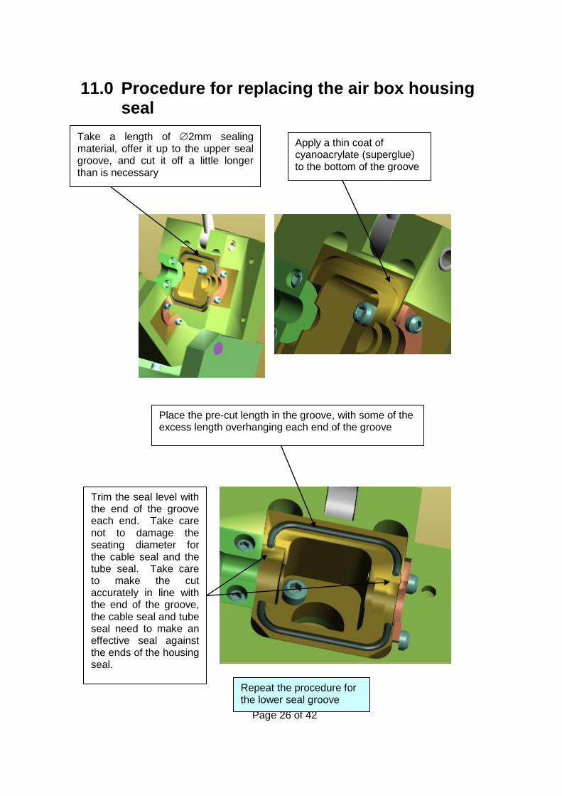
Take a length of 2mm sealing material, offer it up to the upper seal groove, and cut it off a little longer than is necessary
11.0 Procedure for replacing the air box housing seal
Apply a thin coat of cyanoacrylate (superglue) to the bottom of the groove
Place the pre-cut length in the groove, with some of the excess length overhanging each end of the groove
Trim the seal level with the end of the groove each end. Take care not to damage the seating diameter for the cable seal and the tube seal. Take care to make the cut accurately in line with the end of the groove, the cable seal and tube seal need to make an effective seal against the ends of the housing seal.
Repeat the procedure for the lower seal groove

Page 27 of 42
12.0 Procedure for changing the airbox infeed guide
13.0 Procedure for changing the drive rollers The machine is fitted with standard rollers, tests have shown that these rollers give a good compromise of life and grip. There may be circumstances when a roller with much higher grip will be needed. If, for instance it is necessary to install a cable, which will sustain crushing damage when light compression forces are applied to it. It will be necessary to use a roller with a surface coating with high friction characteristics. This will allow the cable to be pushed with high torque whilst being compressed lightly. If this type of roller is needed the CBS Products Ltd sales office will be able to advise on part numbers etc. To fit this roller it will be necessary to remove the standard roller, the procedure is as follows.
Remove the airbox infeed guide
Loosen and remove the (2) m3 fixing screws. (Do not mislay these screws, they will be needed to fix the new infeed guide.
Repeat the procedure for the infeed guide insert in the other hosing half
To fit the new guides, reverse the disassembly procedure
Loosen and remove the fixing screw and washer
Remove the roller
Repeat the procedure for the other roller
To fit the new rollers, reverse the assembly
procedure

Page 28 of 42
14.0 Monthly service – check list This section is included in the manual for your convenience, there follows a list of suggested checks, it is recommended that these checks be carried out on a regular basis, depending on use. Monthly checks are convenient; a few minutes can be set aside on the same day of each month to complete these simple checks. The next section of this manual is an empty table, the dates when these checks and all other service and repair jobs are completed can be entered into the spaces provided in this table. This will give the user a record of what service has been carried out and when.
1. Check the tool box, ensure all tools and interchangeable parts are present, clean and
ready for use. 2. Clean the outside of the machine, take care not to damage the rollers or springs. 3. Check the measuring wheel, ensure it runs freely, and that the speed/distance
functions respond when the wheel is rotated. 4. Check the measuring wheel fixed roller, make sure it rotates freely. 5. Loosen the thumb nuts locking the top plate of the cable guide (outfeed) in position,
ensure the plate is free to move backwards and forwards. 6. Clean the exposed threads on the swing bolts that hold the air box and tube clamp
assembly together. Add a smear of grease/oil to prevent build up of surface corrosion and to ensure smooth operation of the thumb nuts.

Page 29 of 42
15.0 SERVICE HISTORY RECORD
Service no Date Carried out
by Record of service/repair

Page 30 of 42

Page 31 of 42
16.0 Tube integrity and Lubrication
This is entirely the responsibility of the operator. To be sure that the tube into which the cable is to be inserted is installed appropriately, it is recommended that its integrity and lubrication be checked.
i.e. check that the tube is: 1. Not blocked 2. Not squashed 3. Continuous (i.e. it has not been fractured somewhere along its route and the fractured
ends separated) 4. Also check that any joins are pressure tight 5. Finally check that the tube is appropriately lubricated. The easiest and most straightforward way to complete these checks is to set the machine up for a normal cable insertion but fit a seal in place of the cable. The tube can then be pressurised without running the roller drive.
CAUTION: ANY OBJECT INADVERTENTLY LEFT IN THE TUBE
DURING THE TUBE LAYING MAY BE EXPELLED FROM THE END
OF THE TUBE WITH HIGH FORCE AND VELOCITY. IT IS
IMPERATIVE THAT NO PERSONNEL BE IN THE VICINITY OF THE
END OF THE TUBE OR THAT A SUITABLE DEVICE IS FITTED TO
THE END OF TH E TUBE TO ARREST ANY EXPELLED OBJECT.
The checks listed at 1-4 (inclusive) above may all be carried out at the same time using one check. The procedure is outlined below. Set up the air box and tube clamp as shown right.
When the air box has been set up as shown in the sketch. The air box and tube clamp should be closed as for usual cable installation.
Fit the appropriate plug as shown (see Appendix for plug number)
Fit the air box seal, tube and tube seal in position as for normal cable installation

Page 32 of 42
The air box and tube clamp are now set up to blow air through the tube. Connect the air as for normal blowing. Make sure there are personnel at the other end of the tube run, and that they are aware that the air is to be turned on. Make sure that a suitable device is fitted (a catcher is available from CBS Products (KT), Ltd; speak to our sales department for details) to obviate injury should any object be expelled from the far end of the tube. The far end of the tube run should be monitored, air should be leaving the tube under reasonable pressure. The minimum pressure required will vary with the length of tube in the run, the friction characteristics of the tube and the cable and the lubrication being used. However, as a starting point the air leaving the far end of the tube should be (at least) similar to a light breeze. Bear in mind that if the tube run is of considerable distance, it may take a few minutes for the air to reach the far end of the tube. If after waiting a suitable time there is no air leaving the far end of the tube, this would indicate that there is a blockage or similar obstruction in the tube run, or, that the tube is fractured. In either case the fault should be corrected before any attempt is made to blow cable down the tube. Once the tube integrity has been confirmed by the method outlined above. The tube may be lubricated. Open the air box and tube clamp assembly, as shown in the sketch above, withdraw the tube and raise it so that the lubricant will pour into it easily and not overflow from the top. Pour lubricant of recommended quality and quantity down the tube (A recommended quantity is 100ml per 1km of tube length). Insert a suitable foam plug into the tube and put the tube back into the air box and tube clamp as shown in the sketch above. The air box and tube clamp assembly are now set up to blow the foam plug through the tube, the foam plug will help to deposit an even coating of lubricant to the inside walls of the tube. Connect the air as for normal blowing. Make sure there are personnel at the other end of the tube run, and that they are aware that the air is to be turned on. Make sure that a suitable device is fitted (a catcher is available from CBS Products(KT) Ltd; speak to our sales department for details) to obviate injury should any object be expelled from the far end of the tube. When the foam plug has been expelled from the far end of the tube run, cable can be installed into the tube. Note: when the air is turned off, after checking the tube integrity and sending the foam plug down the tube to spread the lubricant. It may take some time for the pressure in the tube to dissipate, time must be allowed for the pressure to fall back to low levels.

Page 33 of 42
17.0 Recommended spares list
1. Tube –‘O’ Rings 2. Cable Seal
3. Drive Rollers
4. Cable end tips
5. Lubricant
6. 2.4 mm cord seal
7. 5 AMP & 315 mAMP fuses
For spare parts always quote the machine type and serial number and contact:
CBS Products (KT), Ltd Pillings Road
OAKHAM Rutland
LE15 6QF
TEL: 01572 723665 FAX 01572 756009
E-MAIL: [email protected]
Website: www.cbsproducts.com

Page 34 of 42
1.0 APPENDIX 1 This section lists the appropriate inserts collets etc required for a given cable/tube combination.
TUBE COLLET AND CLAMP ASSEMBLIES
C-1300-TBC-16-01 TUBE COLLET AND CLAMP ASSEMBLY 16 mm O.D.
C-1300-TBC-14 TUBE COLLET AND CLAMP ASSEMBLY 14 mm O.D.
C-1300-TBC-12 TUBE COLLET AND CLAMP ASSEMBLY 12 mm O.D.
C-1300-TBC-10 TUBE COLLET AND CLAMP ASSEMBLY 10 mm O.D.
C-1300-TBC-08 TUBE COLLET AND CLAMP ASSEMBLY 08 mm O.D.
C-1300-TBC-07 TUBE COLLET AND CLAMP ASSEMBLY 07 mm O.D.
C-1300-TBC-05 TUBE COLLET AND CLAMP ASSEMBLY 05 mm O.D.
CABLE GUIDE ASSEMBLIES
C-1300-AS1041-2538 CABLE GUIDE ASSEMBLY 2.5 TO 3.8 mm DIAMETER CABLE
C-1300-AS1041-3855 CABLE GUIDE ASSEMBLY 3.8 TO 5.5 mm DIAMETER CABLE
C-1300-AS1041 CABLE GUIDE ASSEMBLY 5.5 TO 8.0 mm DIAMETER CABLE
C-1300-AS1041-2548 CABLE GUIDE ASSEMBLY 2.5 TO 4.8 mm DIAMETER CABLE
CABLE SEAL COLLET ASSEMBLY
C-1300-CBL-2530 CABLE SEAL COLLET ASSEMBLY 2.5 TO 3.0 mm DIAMETER
C-1300-CBL-3038 CABLE SEAL COLLET ASSEMBLY 3.0 TO 3.8 mm DIAMETER
C-1300-CBL-3850 CABLE SEAL COLLET ASSEMBLY 3.8 TO 5.0 mm DIAMETER
C-1300-CBL-5064 CABLE SEAL COLLET ASSEMBLY 5.0 TO 6.4 mm DIAMETER
C-1300-CBL-6480 CABLE SEAL COLLET ASSEMBLY 6.4 TO 8.0 mm DIAMETER
CABLE SEAL
C-1300-CS-1.4 CABLE SEAL 1.4 mm
C-1300-CS-1.6 CABLE SEAL 1.6 mm
C-1300-CS-2530-5 CABLE SEAL 2.5 TO 3.0 mm (PACK OF 5)
C-1300-CS-3038-5 CABLE SEAL 3.0 TO 3.8 mm (PACK OF 5)
C-1300-CS-3850-5 CABLE SEAL 3.8 TO 5.0 mm (PACK OF 5)
C-1300-CS-5064-5 CABLE SEAL 5.0 TO 6.4 mm (PACK OF 5)
C-1300-CS-6480-5 CABLE SEAL 6.4 TO 8.0 mm (PACK OF 5)
SPARES
TUBE SEAL O RING
C-1300-TS-05-5 TUBE SEAL O RING 05 MM DIAMETER (PACK OF 5)
C-1300-TS-07-5 TUBE SEAL O RING 07 MM DIAMETER (PACK OF 5)
C-1300-TS-08-5 TUBE SEAL O RING 08 MM DIAMETER (PACK OF 5)
C-1300-TS-10-5 TUBE SEAL O RING 10 MM DIAMETER (PACK OF 5)
C-1300-TS-12-5 TUBE SEAL O RING 12 MM DIAMETER (PACK OF 5)
C-1300-TS-14-5 TUBE SEAL O RING 14 MM DIAMETER (PACK OF 5)
C-1300-TS-16-5 TUBE SEAL O RING 16 MM DIAMETER (PACK OF 5)
CHORD SEAL
C-1300-SC-1 SEAL CORD 2.4 mm DIAMETER X 1 METRE LONG

Page 35 of 42
2.0 APPENDIX 2 This section makes recommendations for the initial setting of the torque control potentiometer when installing a cable which has not been installed before, and, whose characteristics are unknown. Generally speaking the torque selector switch should be set to low if the cable diameter is less than 2.5mm or 0.01”. Additionally, softer, black drive wheels are available for cables with low friction coatings.
The sketch to the left shows the torque and speed control potentiometers set in the maximum counter-clockwise position. In this position both torque and speed will be minimum. (Zero)
The sketch to the right shows the torque and speed control potentiometers set in the maximum clockwise position. In this position both torque and speed will be maximum (see specification for details).
The torque control setting will allow the cable to be installed efficiently and without damage. It is of vital importance that the torque setting is made with great care, a little time spent understanding the way to arrive at the optimum settings will save time and frustration during the installation. There are two stages to arriving at the correct torque setting they are described below.
Torque control Speed control

Page 36 of 42
1 Establish the stiffness coefficient from the table below: the stiffness coefficient is a
figure used to represent the diameter and the stiffness of a cable. This figure is only relevant in the context of setting the torque, it has no other relevance. The higher the U figure the stiffer the cable. There is a degree of subjectivity about determining the cable stiffness. What is low stiffness? What is high stiffness? Determining this (the stiffness) relies upon the user having some familiarity with bundled optical fibre cables, this will give the experience to assess whether the cable has low, medium or high stiffness. For instance a small diameter cable with high stiffness may be less stiff than a large cable with medium stiffness. The table reflects this. If there is any doubt, in the first instance err on the low side, i.e. select a lower U figure.
Cable dia (mm)
Cable stiffness Stiffness coefficient (U)
2.0 - 3.5
Low U1
Medium U1
High U2
3.5 - 5.0
Low U1
Medium U2
High U3
5.0 - 6.5
Low U2
Medium U3
High U5
6.5 - 8.0
Low U2
Medium U4
High U6
2 Assess the coefficient of friction of the cable insulation (the outer coating). Is it low
or high. Once again this relies on the user having some experience with bundled optical fibre cables. As a guide, if the surface feels smooth and dry the coefficient of friction will be low, if you slide your hand over the surface does it snatch your flesh? If it does the coefficient of friction will be high. As above, if there is any doubt, err on the low side i.e. select a lower coefficient of friction.

Page 37 of 42
3 Referring to the chart below. The “x” axis (the bottom line) represents the
coefficient of friction; 1 is very low: 10 is very high. Look along this line from left to right. Pick a vertical line that is approximately the value of the coefficient of friction. Look vertically upward along this line. It crosses a series of angled lines, these lines are numbered U1, U2 etc. where the vertical line crosses the angled line with the U figure determined from step 1 make a mark on the chart. Draw a horizontal line (parallel with the other horizontal lines on the chart) from the marked point. Where this line crosses the “y” axis (the vertical line at the extreme left hand of the chart), make a second mark on the chart. The height of this line represents the % of maximum clockwise rotation of the torque control. If this line is very close to the figure 0.5 marked on the “y” axis, set the torque control potentiometer approximately one half of the way around its maximum travel etc.
There is an alternative way of arriving at the appropriate setting for the torque control potentiometer. Do the following. Select a sample of the cable to be used. Pass the cable through the machine as described in the manual. Feed the cable into the beginning of a length of sample tube (say 5 metres long). Seal the open end of the tube. Position the torque control potentiometer at the position determined by the recommendations in this Appendix, Start the machine. Drive the cable hard into the sealed end of the sample length of tube. The rollers will stop turning, this is because the torque limit has been reached. Repeat this procedure, each time turning the torque potentiometer a little further clockwise. Eventually, the cable will buckle. The setting of the torque control potentiometer is now a little too far clockwise. Turn it back (counter clockwise) a little. This is the optimum setting.
Torque potentiometer setting
0
0.25
0.5
0.75
1
1 10
Coeff of friction
% o
f m
ax
imu
m r
ota
tio
n (
clo
ck
wis
e)
U1
U2
U3
U4
U5
U6

Page 38 of 42
Note: This method may also be used to set the clamping force of the rollers on the cable. Initially, the clamp arm lever should be set so that the rollers press very lightly onto the cable. Carry out the test outlined above (drive the cable into the closed end of a sample tube). The rollers will slip. Repeat this procedure, each time increasing slightly, the pressure the rollers apply to the cable. Eventually the rollers will stop turning because the torque limit has been reached. It is worth noting at this stage that this approach may result in a great deal of force being applied to the cable. More than the cable can withstand without sustaining damage, sometimes it may be that the cable may be protected from buckling by a combination of torque control setting and slip. The main purpose of the exercise is to install the cable as far as possible without causing damage to the outer sheath, in some circumstances a compromise may be found that uses a degree of torque control and slip.

Page 39 of 42
3.0 APPENDIX 3 Programming Parameters for CUB5B counter/rate meter fitted to Breeze machines – Breeze Serial Numbers 0121 Onwards
The device must be wired and installed into the machine prior to programming.
Breeze is fitted with C-M-DEV-CUB5B, backlight version The DIP switch positions are as follows: 1 OFF 2 OFF 3 OFF 4 OFF Please see the attached CUB5 Programming Overview attached to this document.
• Press and hold SEL for 2 seconds to enter programming mode
• Enter the Pro-Code – 111 by pressing RST to change numbers and SEL to skip to the next number.
• Once correct Press and Hold SEL for 2 seconds
• Pro-no should now be flashing, press RST
• Press RST to move through the various sections 1-input, 2-rate 3-dsplay, sections 4 and 5 will be unavailable, see the next page of instructions for the parameters required.
• Press SEL to enter that section
• To change the value of a parameter press RST
• Press SEL to move to the next parameter (You will have to hold for 2 seconds on certain parameters).
• When all the parameters in the section have been scrolled through you will return to the Pro-no display, press RST to scroll to another section else press SEL to exit programming mode.

Page 40 of 42
First reset the current settings to Factory Settings on the counter: Scroll to 3-DSPLAY
Skip through the parameters until FACT SET is displayed. Change this to YES by pressing RST PRO NO should be displayed, Press SEL.
Continue to re-program the Counter by pressing and holding SEL to re-enter programming mode. Pro-no will be displayed, press RST to move through the relevant sections. The following parameters are required for the Tornado counter: Press RST Once: Counter Parameters (1-INPUT) INPA-B = Cnt ud – if correct press SEL. CNT A DP = 0 - if correct press SEL. CNT A SCF = 0.0102 (Metric, m) or 0.0335 (Imperial, ft) – once correct press & Hold SEL. CNT A RST = TO ZERO - if correct press SEL. CNT A DIR = NOR - if correct press SEL. CNT A LD = 0 – once correct press & Hold SEL. CNT B BAT = NO - if correct press SEL. RST P-UP = NO - if correct press SEL. USER INP = NO - if correct press SEL. Press RST Twice: Rate Parameters (2-RATE) RATE ENB = YES - if correct press SEL. RATE DP = 0 - if correct press SEL. RATE DSP = 60 - once correct press & Hold SEL. RATE INP = 97.9 (Metric, m/min) or 29.8 (Imperial, ft/min) – once correct press & Hold SEL. LO-UDT = 1.0 - if correct press SEL. HI-UDT = 2.0 - if correct press SEL. Press RST Three times: DISPLAY (3-DSPLAY) SEL ENB = YES - if correct press SEL. RST ENB = YES - if correct press SEL. D-SCROLL = NO - if correct press SEL. D-COLOR = RED – if correct press SEL. D-LEVEL = 5 - if correct press SEL. PRO CODE = 111 – CODE REQUIRED TO RE-PROGRAM - once correct press & Hold SEL. CODE VER = NO - if correct press SEL. FACT SET = NO – Press SEL Twice

Page 41 of 42

Registered in England No: 10774860. VAT No: GB 269 8426 50. Registered Office: Westgate House, Royland Road, Loughborough, LE11 2EH
EC Declaration of Conformity In accordance with EN ISO 17050-1:2004
We CBS Products (KT) Ltd
Of Pillings Road, Oakham, Rutland, LE15 6QF
In accordance with the following Directive(s):
2006/42/EC The Machinery Directive
2014/35/EU The Low Voltage Directive
2014/30/EU The Electromagnetic Compatibility Directive
Hereby declare that
Equipment Breeze
Model Number C-1300-05-T
Serial Number
has been designed and manufactured to the relevant parts of the following standards
Ref No.
BS EN ISO
12100:2010
BS EN 61000-6-
1:2007
BS EN 61000-6-
3:2007+A1:2011
Title
Safety of machinery – General principles for design – Risk assessment
and risk reduction
Electromagnetic Compatibility (EMC) – Generic Standards –
Immunity for residential, commercial and light-industrial
environments.
Electromagnetic Compatibility (EMC) – Generic Standards –
Emission standard for residential, commercial and light-industrial
environments.
Edition/Date
2010
2011
2010
I hereby declare that the equipment named above has been designed to comply with the relevant sections of the
above referenced specifications and is in accordance with the requirements of the Directive(s)
Signed by……………………………………………………………………………….
Name: Mr Andrew Sibun
Position: Technical Manager
Done at: Oakham, United Kingdom Document Ref No.
On: 25 January 2018 C-1300-05-T/CE
The documentation for the machinery is available from:
Name: CBS Products (KT), Ltd
Address: Pillings Road, Oakham, Rutland, LE15 6QF