operating manual - craft beer bottling filling machine ... · pdf file4 on/off: main power to...
TRANSCRIPT

M4 & M6 BOTTLE FILLING MACHINE
OPERATING MANUAL
“Q” SERIES
12/14/13
(Rev. 6/26/14)

2
TABLE OF CONTENTS
GENERAL .......................................................................................................................................3
CONTROL PANEL .........................................................................................................................3
SAFE OPERATION OF THE BOTTLING MACHINE .................................................................5
PROCEDURE FOR CLEANING AND SANITIZING ...................................................................5
OPERATING SUMMARY .............................................................................................................6
SANITIZING .......................................................................................................................7
BOTTLING ..........................................................................................................................8
AUTO FILLING ..................................................................................................................9
AUTO CLEANING ...........................................................................................................12
CLEANING .......................................................................................................................14
MANUAL OVERRIDE .................................................................................................................15
RUN LEAK TEST .............................................................................................................16
ADJUSTMENTS OF THE MACHINE .........................................................................................17
BOTTLE INDEXING & FILL HEAD ALIGNMENT ......................................................17
CAP FEED .........................................................................................................................17
COMPUTER .................................................................................................................................18
TROUBLESHOOTING .................................................................................................................19
PRESSURE SENSOR CHECK .....................................................................................................21
LUBRICATION & MAINTENANCE ..........................................................................................21
FILL MANIFOLD & TUBING MAINTENANCE .......................................................................22
BOTTLE DETECTION SYSTEM/INDEX PLATE ADJUSTMENT ..........................................24
BOTTLE DETECTION BY-PASS ................................................................................................25
BOTTLE INDEXING SPEED ADJUSTMENT............................................................................25
WARNING
AS WITH ALL MECHANICAL EQUIPMENT, CARE MUST BE TAKEN
TO AVOID INJURY FROM MOVING PARTS WHICH OPERATE WITH
CONSIDERABLE FORCE AND WITHOUT WARNING. MEHEEN
MANUFACTURING SHALL NOT BE HELD LIABLE FOR INJURY OR
DAMAGE RESULTING FROM THE INAPPROPRIATE USE OF THIS
MACHINE OR FROM NORMAL OPERATION WITHOUT REGARD TO
NORMAL SAFETY CONSIDERATIONS. MEHEEN MANUFACTURING
SHALL BE HELD HARMLESS IN THE CASE OF INJURY RELATED TO
THE USE OF THIS MACHINE REGARDLESS OF THE
CIRCUMSTANCES AND OPERATING PROCEDURES USED.

3
GENERAL
The M4 & M6 automated bottling machines are designed with quality and portability in mind.
An onboard computer controls all automated functions including bottle fill levels and pressures.
Standard automated features include sanitizing, cleaning, filling and crowning.
The M4 & M6 are specifically designed for bottling carbonated beverages, under cold counter
pressure conditions, directly from the bottling tank. Generally optimum bottling conditions are
cold (30-340F) and 2.0-3.0 volumes dissolved CO2.
A compressed air source that can provide 100psi + is required to operate the M4 and M6, as well
as 110 volt AC electrical power and a regulated CO2 source. Meheen Manufacturing suggests
the use of an oil sump, reciprocating type air compressor with a min of 15scfm@90psi rating.
DO NOT use a home-style, direct drive oil-less compressor. Regulated air pressure on the
machine itself needs to be 95-100psi. Minimum air hose size is 3/8” inside diameter for a 50’
hose or less and larger for longer runs. Also all devices restricting air flow, such as regulators
and moisture traps should be removed between the air compressor and the bottling machine.
CONTROL PANEL
The control panel of the M4 and M6 bottling machines consist of the operator interface shown
above and a large red mushroom switch which is located near the bottom center of the panel.
The opening screen gives information about the M4 and M6 machines, such as Brewery Name,
Serial#, interface and computer program version. This screen appears each time the machine is
turned on. To access the main operating screen, simply touch the wizard and the screen will
change to the main operating screen.

4
On/Off: Main power to the machine is turned on by pulling the red mushroom button out, and
turned off by pushing it in.
Main Screen: The main operating screen shown below allows you to choose the function
needed. You may return to the main operating screen from any of the operating screens by
pressing the Reset key and then the main button with the wizard pictured on it.
Auto Filling, Clean, Sanitize and Manual Override: These operations are entered
from the Main screen shown above by pressing the desired button. When any of these buttons
are pressed the screen will change to that operation. Note: The Reset key must be pressed before
starting any operational mode except the manual override functions.
Reset: The Reset button is used any time the machine has been stopped, paused, or about to be
started in a new mode. The Reset always returns the machine to its starting conditions for each
mode. Reset must be used each time the machine enters a new operation before the machine will
start any program functions and before pressing the Main screen button.
CAUTION: If the bottling machine is paused and rapidly Reset during a time when the
machine has pressure in the bottle (i.e., filling), pressure in the bottles will be released
rapidly without warning. Rapid release of pressure can be hazardous due to glass
breakage and liquid spray.

5
SAFE OPERATION OF THE BOTTLING MACHINE
During normal operation of the M4 and M6 several very powerful moving parts are utilized that
could cause serious injury if proper precautions are not taken. Even though bottles are designed
for much higher pressures than utilized by the bottling machine, manufacturing defects can exist
which can cause bottle failure resulting in breakage and potentially flying glass. Meheen
Manufacturing recommends the following safety precautions be observed while operating the M4
and M6:
1. Always wear safety glasses or other eye protection.
2. Avoid loose fitting clothing which could become caught in moving parts of the
machine.
3. Keep hands and face away from moving parts of the machine at all times when air
pressure is connected to the machine.
4. Do not exceed 40 psi CO2 to the machine at any time, damage to the pressure sensor
will occur.
5. Avoid direct water spray on the control panel and electrical parts.
6. Components located inside the control panel operate on 24VDC, high voltage (100-
220 Volts AC) energy is converted by a power supply located on the cord. DO NOT
open the control panel or power supply when plugged in.
7. Service of electrical components should be referred to qualified personnel only.
PROCEDURE FOR CLEANING AND SANITIZING
Even though the products mentioned in this procedure are supplied by Birko Corporation any
brand can be used. Birko products can be purchased from:
1. Dissolve four ounces (one-half cup or about 125 grams) of Birko CELL-R-MASTR™ in
5 gallons of 120-1300F water.
2. For light-duty cleaning, circulate the CELL-R-MASTR™ solution through the machine
for a minimum of 2-4 minutes. For heavily soiled machines, circulate the solution
through the machine until clean. Do this by operating the machine in the Sanitize mode
as many times as needed.
3. Drain CELL-R-MASTR™ solution, and then rinse the machine with ambient or warm
water until the pH of the rinse water is the same as the pH of the tap water. For final
rinse, operate the machine in the Clean mode to blow out the tubing before storing the
machine.
Birko Corporation 9152 Yosemite Street Henderson, CO 80640-8027 (800) 525-0476
6
4. Prior to bottling, sanitize using an appropriate no-rinse sanitizer such as Chlorine Dioxide
(ClO2) or Peracetic Acid (PAA). Operate the machine in the Sanitize mode.
To remove beer stone (Calcium Oxalate) deposits, the use of an acid product such as Acid Brite
No.2 (Phosphoric/Nitric blend) is recommended. Run 1 ounce (30ml) of acid per gallon of warm
(1200F) water for a minimum of 2-4 minutes prior to CELL-R-MASTR™.
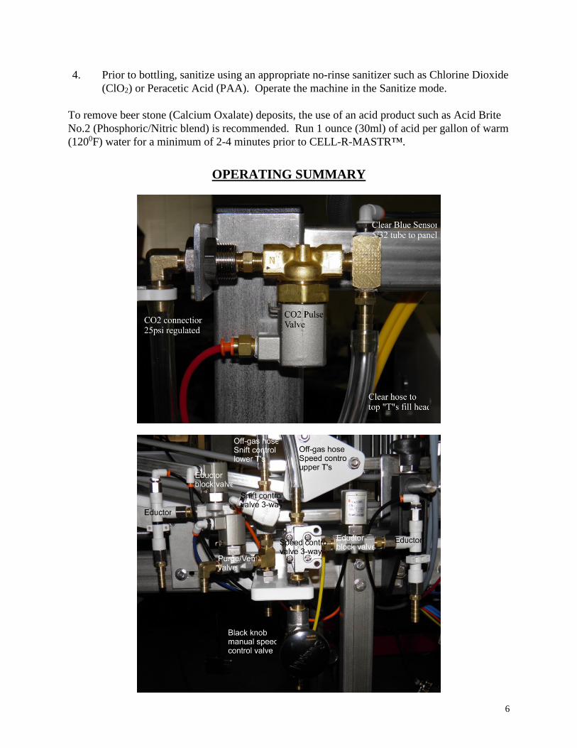
OPERATING SUMMARY

7
Sanitizing:
1. Mix a sufficient amount of sanitizing solution (about 5 gallons) to keep the pump
submersed during sanitation. Most sanitizing solutions which require less than 2 minutes
of contact time to be effective can be used.
2. Connect air pressure to the bottling machine before loading caps or connecting the
sanitizing pump to the machine.
3. Fill cap feed ramps with caps, seal side down.
4. Connect the hose to be used for bottling between the sanitizing pump and the beer
distribution manifold on the bottling machine. Be sure to clamp both ends of the hose
securely.
5. Disconnect the 5/32" liquid line pressure sensor hose (small tubing) from the pressure
sensor located in the bottom of the control panel. To disconnect the hose, depress the
collar of the tube fitting and pull the hose out. Place the end of the hose you just
disconnected below the machine into a bucket or drain. Sanitizing solution will flow
through this line when the pump is started.

8
6. Place three rows of bottles on the bottle runway at the base of the bottle feed ramp.
When the bottling machine is started it will automatically index the bottles to the filling
and crowning stations.
7. Press the Reset button on the interface and the “System is Reset” message will appear at
the bottom of the screen.
8. Place the sanitizing pump into the bucket of sanitizing solution and plug it in.
9. Press the Sanitize Off/On button to begin the sanitizing cycle. The button will change
color from red to green and the green RUN light will illuminate at the top of the screen.
A message in the bottom message bar will have the word “Sanitizing” displayed. The
machine will automatically perform two 1 minute sanitizing cycles then stop Illuminating
the PAUSE light and display in the message box “Sanitizing Complete”.
CAUTION: The bottle filling head will come up without warning to index the next row
of bottles. Keep hands and face away from moving parts at all times.
10. Bottle caps in the cap feed ramps will automatically feed into the capping head each time
the capping head cycles to the up position. The cap feed ramps hold enough caps for 2-3
cases of bottles. More caps can be added to the cap feed ramps at any time.
11. The machine automatically stops at the end of the second sanitizing cycle with the filling
heads down. The amber PAUSE light in the center of the interface will be lit when the
cycle is complete and the message display will read “Sanitizing Complete”. Press the
Sanitize button to turn the program off. The button will turn red and the message display
will show “System is Reset”. Do not remove bottles filled with sanitizing solution from
the bottling machine as they will be needed for weight to provide proper bottle feeding
when starting the automatic bottling cycle. When the Sanitize cycle is complete, unplug
the pump to stop solution still being pumped through the liquid pressure sensor hose.
You may now press the “Main” button with the wizard’s image to return to the Main
Operation Menu.
12. Allow the liquid pressure sensor hose from the beer distribution to drain before
connecting to the control panel. After the pressure sensor hose is drained, reinstall it on
the bottling machine by pushing the hose firmly into the fittings on the sensor and beer
manifold. Note: The tubing is often difficult to push into the fittings. You should feel
the tube slide into the fitting and seat when it is installed properly.
Bottling:
1. Connect the hose used for the sanitizing cycle from the distribution manifold of the
machine to the product dispensing tank. Be sure to clamp both ends of the hose securely.
Open the dispensing tank valve very slowly when first charging the line. If the tank valve
is opened too fast, severe damage may occur to the beer line pressure sensor.

9
2. Connect the CO2 supply to the CO2 inlet on the top of the bottling machine and adjust the
pressure to 25psi. This CO2 source is used to purge the bottles, bring them to counter
pressure and pulse the full bottles. DO NOT EXCEED 40 psi to avoid damage to
pressure sensors on the machine.
3. Adjust the CO2 pressure applied to the head space of the dispensing tank 1-2 psi above
the tank equilibrium pressure or an adequate level to dispense the product into the bottles.
4. Place 4-5 rows of bottles on the sloped bottle feed ramp to begin the bottling process.
The full bottles from the sanitizing cycle should remain on the machine until enough full
bottles have accumulated on the machine to keep the bottle feeding system operating
properly. As full bottles accumulate on the exit portion of the machine, more bottles can
be added to the bottle feed ramp. The full bottles provide the needed friction for the
bottle gravity feed system to operate properly, and keep the bottles being indexed from
sliding too far and misfeeding. Once the machine is operating in the bottling mode, at
least 6 rows of full bottles must be maintained on the exit portion of the machine.
Auto Filling:

10
5. The Auto Filling screen is shown above and consists of three slide bars, two pressure
meters, manifold temperature display and Auto Off/On, Reset, Pulse, Evac/Purge, Liquid
psi Control buttons and Liquid psi arrow key adjustment with pressure display. The first
time the machine is turned on, leveling will be at 0.0 which indicates no leveling time
after bottles have been detected full. To add leveling time, slide the leveling slide bar up
to the desired time. The Fill Sensor will be in the Auto mode and the slide for the
Manual mode will always default to “10”. This is quite sensitive for fill detection at low
filling speeds. When the Fill Sensor is in the Auto mode, it will automatically adjust to
changing pouring conditions and is not adjustable by the operator. Should the Auto Fill
Detection fail to work properly, it may be changed to Manual adjustment by pressing the
selector button at the top of the Fill Sensor. The color of the button will change from
green to blue and the text will change to Manual indicating the mode change for Fill
Detection. As filling speeds are increased in the Manual mode, the Fill Sensor will need
to be raised to a higher number to ensure the bottles are completely filled. The “Low
Pressure” slide is used to adjust how much pressure is in the bottles when the filling
heads are raised, or the pressure at which the Pulse will occur. It is generally
recommended to operate the Low Pressure as low as possible and still maintain a 1
second or less time from when the filling valve closes until the filling heads are raised
from the bottles. If the filling heads remain in the bottle more than 1 second after the
filling valve has closed, you need to raise the Low Pressure until the 1 second has been
met. The two pressure bars simply display incoming product pressure to the machine and
the pressure in the bottle. It can be used for adjustments to the machine or trouble
shooting any problems such as “counter pressure fail” or fill detection issues.
6. The M4 and M6 control panels also display temperature in the product manifold located
at the top of the machine. This temperature display simply lets the operator observe the
incoming temperature of the product and can be used to help with determining proper
pressures in the liquid tank.
7. A button labeled “Liquid psi Control” (LpC) is located in the upper right hand portion of
the display. This button turns on and off the controls to adjust CO2 dispensing pressure in
the head space of the tank based on liquid manifold pressure at the machine. This
function is optional and intended to help resolve dispensing pressure drops that can occur
when using manual style regulators. To utilize this feature, an independent CO2 source,
different from the one used for the bottling
machine, is connected to the control valve inlet
(see photo). The inlet pressure should be set at 30-
35 psi from the CO2 source. A hose will need to
be connected between the control valve and head
space of the dispensing tank.
How LpC works, is when connected to a CO2
source and the head space of the dispensing tank
and the system is activated by pressing the “Liquid
psi Control” button. The computer initially
records the static liquid pressure at the manifold
and displays that pressure as the set point above

11
the adjusting arrow keys. Using the arrow keys you can adjust this set point up or down
as needed. Each cycle, before the product valve opens the computer, will sample the
manifold pressure and turn the CO2 control valve on or off as needed.
NOTE: This system is limited to a maximum control pressure of 14.9 psi and only operates
when the filling process is running. It does not function when the machine is paused.
8. Press the Reset button on the operator interface and the message display should read
“System is Reset”. Press Auto Filling to start the machine in its automatic filling and
capping mode. The message display will display “Automatic Filling”, the Run light will
be illuminated and the Auto Filling button will change from red to green. To adjust the
Low Pressure and Fill Sensor simply move the slide bars to the desired amount.
Adjusting the Fill Sensor to a higher value makes it less sensitive and a lower value
makes it more sensitive.
Pre-Purge is the default operation of the machine, where the atmosphere in the
bottles is purged with CO2 before counter pressure and filling. Additional purge time can
be programmed using the arrow keys at the bottom of the screen. Press this button again
and the operation changes to Evac/Purge, drawing the atmosphere from the bottles then
purging before counter pressure and filling. Press this button again and the machine
performs a double evacuation of the bottles, then counter pressures for filling.
Pulse (Optional): Generally it is recommended to operate M4 and M6 in the Auto
Filling program with the Pulse button off. When the Pulse button is on, a rapid pulse of
CO2 is blown into the bottles after they are filled. This pulse creates seed bubbles in the
beer and causes foaming prior to capping the bottles. The Low Pressure adjustment
described above is the amount of pressure left in the bottles when the pulse takes place.
The intensity of the pulse is controlled using the horizontal slide bar labeled “Pulse
Intensity”. The pulse intensity is adjustable from 3-12, with 12 being the highest level
available. If the Pulse is turned off, the machine uses the Low Pressure setting as the
pressure in the bottles when the filling heads will be raised. The Pulse can be turned off
and on during the automatic fill program as needed.
NOTE: The first bottles off the bottling machine will contain sanitizing solution. Be
sure to set those bottles aside so they don't get mixed up with bottles containing
beer.
9. The bottle fill rate is adjusted by using the off-gas flow regulator valve located just below
and to the left of the control panel. Closing this valve slows the flow of liquid into the
bottle, while opening the regulator increases the rate of fill. The fill rate should be slow
enough that the liquid does not foam while the bottles are filling.
10. Once the machine is operating, you can adjust the fill sensitivity as needed to get
consistent fills, and the Low Pressure as needed to control foaming along with turning the
Pulse on or off.

12
11. To PAUSE the machine at any time during automatic filling, press the Auto Filling
button and the machine will stop in the safe shut down configuration, releasing pressure
from the bottles with the filling head down. When the Reset button is pressed the
machine will reset and the filling heads will go up. Once the machine has been reset you
can start another Auto Filling operation by pressing that button or press the “Main”
button with the wizards image to go to the main menu.
Auto Cleaning:
1. Make sure the air and power are still connected to the machine and enough filled rows of
bottles remain on the machine for proper feeding. Also leave at least 3 rows of empty
bottles on the bottle feed ramp.
2. Connect the product hose to the sanitizing pump ensuring the other end is connected to
the product manifold on the bottling machine.
3. Immerse the sanitizing pump in an adequate volume of clean water or cleaning solution.
Most cleaning solutions are acceptable with the exception of acid based materials that can
damage the internal parts of valves used in the off-gas system. Remember you will be
filling 2 rows of bottles and washing through the off-gas system.

13
4. Disconnect the 5/32" liquid pressure sensor hose (small tubing) from the pressure sensor
located in the bottom of the control panel. To disconnect the hose, depress the collar of
the tube fitting and pull the hose out. Place the end of the hose you just disconnected
below the machine into a bucket or drain. Cleaning solution will flow through this line
when the pump is started in the next step.
5. Disconnect the CO2 purge/pulse hose from the top of the machine and place the ends in a
bucket or to a drain. Cleaning solution or water will flow through this hose when the
sanitizing pump is plugged in.
6. Plug in the sanitizing pump.
7. Be certain you have at least 3 rows of empty bottles on the machine and press the Clean
button. The machine will begin the program and “Cleaning” will appear in the message
display and the Clean button will change from red to green. The RUN light will also be
illuminated.
8. During the cleaning cycle it is acceptable to hose off the machine and bottling area. Care
should be taken to keep water from splashing on the control panel and electrical devices.
9. The cleaning cycle will fill 2 rows of bottles with solution flowing through the CO2
purge/pulse hose removed in step 5 as well as from the valves under the machine. At the
end of the second cycle the machine will stop with the filling and capping heads down
and the operator interface will display the following instruction: “Reconnect hoses
and/Reset to continue”. Reconnect the CO2 purge/pulse hose and press the Blow Out
button. The machine will index one more row of bottles, the filling and capping heads
will come down and CO2 will flow from the system for 15 seconds to complete the
cleaning. When cleaning is complete the fill head and capping head will remain down
and “Cleaning Complete” will be displayed in the message display. The filling heads can
be raised by pressing the Clean button to turn off the cycle and pressing the Reset button.
10. When the cleaning cycle is complete, unplug the pump, as cleaning liquid will continue to
flow through the pressure sensor hose until the pump is unplugged. Leave the beer line
pressure sensor hose disconnected from the pressure sensor and hang vertically to
promote draining.
11. During the cleaning cycle the off-gas regulating system is flushed and blown out with
CO2 and should be clean. No other cleaning of this system should be required.
12. When the cleaning cycle is complete, be sure to remove all bottle caps from the cap
feeding ramps before disconnecting the air supply. If caps are not removed from the
machine when the air source is disconnected, they will all fall into the capping head and
jam the cap feeding mechanism. Also pull rubber bottle seals down or remove them and
clean behind them so that no moisture remains behind the seals.
13. After the cleaning cycle is complete, it is recommended that excess moisture and debris
be blown off the machine using compressed air. The bottler is now ready to be stored for

14
the next use. Never use high pressure air, gas or city water to blow out the fill
manifold while the 5/32” pressure sensor hose is connected to the bottom of the
control panel. Damage to the pressure sensor due to over pressurization is not
warranted by Meheen Manufacturing.
Cleaning:
Auto cleaning does a good job of rinsing the internal parts of the bottling machine and leaves it
relatively clean; however, we recommend extra cleaning be performed on a regular basis to
ensure good quality of your beverages and to avoid contamination. For this cleaning the filling
head, distribution manifold and fill tubes should be removed from the machine and washed in a
warm caustic or PBW solution which will remove protein and other contaminates from internal
surfaces. The frequency of this type of cleaning will depend on the beverages and amount of use,
as well as the cleaning requirements of your facility.
1. With the machine turned off, and all product lines, air, CO2 and electricity disconnected,
disconnect the pressure sensor hose and the clamps and hoses connected to the bottom of
the manifold. Remove the liquid manifold by removing the two bolts that secure it to the
frame.
2. Loosen or remove the screws for the tubing support clamps on the front of the filling head
carriage. Then, disconnect the tubing from the front of the filling head by pressing in on
the fitting collar while pulling the tubes out. Remove the filling head from the carriage
by removing the two bolts that secure it to the carriage.
3. Remove the silicone filling tubes from the stainless steel filling tubes and discard them.
Remove the filling tubes from the filling head carefully to avoid bending them. Remove
rubber bottle seals.
4. Place the manifold, filling head and filling tubes in a container with the cleaning solution.
Cleaning solution may be circulated with the sanitizing pump provided the operating
temperatures and cleaning solution used is compatible with the pump specifications. If
the sanitizing pump is used to circulate cleaners, be cautious and take all safety
precautions to avoid being splashed by hot cleaners.
5. After cleaning is complete, rinse all parts thoroughly with water to remove all cleaner and
reassemble the machine. Always flush the inner surface of the crowning heads
thoroughly with water to remove any residual beverage deposits which may cause
contamination.

15
MANUAL OVERRIDE
A Manual Override system is incorporated into the control systems of the M4 and M6 bottling
machines, which allows you to operate any function on the machines without operating an
automated cycle. Manual overrides are very useful for adjusting the machines for new bottles,
trouble shooting components and verifying the operation of sensors. The overrides are accessed
from the Main Menu by pressing the Manual Override button.
From the Manual Override screen shown above you can actuate any of the items on the machines
by simply pressing the labeled buttons. The activated button will turn green while pressed
indicating it is activated. The corresponding item on the machines should respond while
activated. The “Bottle Detection Controls” button will load that page on the screen, see page 24.
Bottle and Liquid pressure meters at the right side of the screen will indicate the pressure applied
to each of the sensors in the control panel. These displays are very useful to verify proper
operation of each of the sensors which are critical for proper operation of the bottling machine.
At the bottom of the screen the “Rows of 10,000” and” Rows of bottles” are displayed. By
multiplying the number displayed in the left counter by 10,000 and adding it to the counter on the
right you can determine the total rows of bottles filled.

16
Run Leak Test:
From the Manual Override screen press the Run Leak Test button and the following screen will
be displayed.
Place bottles on the machine so that empty bottles will be indexed under the filling head when
the machine is started. Have compressed air and CO2 connected to the machine as you normally
would and press the Start Leak Test button to begin the leak test. Bottles will be indexed under
the filling heads and pressurized with CO2 and you will see the pressure rise at the right of the
screen. A leak test is performed by bringing the bottles up to a certain pressure and monitoring if
pressure is lost or gained over time. If pressure is lost or gained at such a rate that a leak is
detected the leak test will be terminated, the red FAIL light will flash and a text message will be
displayed at the bottom of the screen to identify the problem. This test can determine if a CO2
valve or other valve is leaking into the system causing the pressure to increase as well as pressure
leaking out of the system. Pressure increasing can be CO2 leaking past one of the valves or
possibly compressed air entering the system through a failed off-gas valve. Pressure leaking out
of the system can be any mechanical connection, seal or valve and is the most common type of
leak.

17
[To return the machine to normal operation, press the Start Leak Test button to turn it off and
press Reset, then the Main button to return to the main menu. Once a leak test is stopped, it
cannot be restarted except from the Manual Override screen.]
ADJUSTMENTS TO THE MACHINE
Bottle Indexing & Fill Head Alignment:
This adjustment is made only if it is determined that the bottles are not indexed far enough or are
indexed too far in relation to the capping head. To determine if this adjustment is correct, place
bottles under the capping head then place two rows of bottles under the fill head and lower the
crowner head completely to locate bottles. (NOTE: Make sure the power and air are
disconnected.) Reach under the bottle feed ramp of the machine and push the bottle indexing
bar forward until it is fully extended and push the three rows of bottles on the machine back
against the pushing bar, being careful not to move the pushing bar. Manually lower the capping
head. The holes in the head should be centered with the tops of the bottles directly below them.
The bottles directly under the filling head should also line up with the holes in the bottle locating
guide. If the bottles are not centered, and adjustment is necessary, follow these steps:
1. To adjust the travel of the bottle indexing, remove the end caps from the box tube under
the bottle feed ramp which holds the air cylinder and loosen the two bolts located inside
the box tube. The air cylinder can now be slid forward or backward to adjust the travel of
the bottles so they are centered under the capping head, and the bottles under the filling
head are centered in the bottle locator with the air cylinder fully extended. When the
required location of the air cylinder has been found, tighten the two bolts for the air
cylinder.
Cap Feed:
The cap feeding mechanism should not require adjustment unless a bottle size change is made
which may require new riser blocks be installed. Contact Meheen Manufacturing regarding any
bottle size changes.
NOTE 1: For crowns to feed properly, the crown feed shoots must be kept dry during
operation and the crowning head must be fully in the up position when crowns are
dropped. If the crown shoots become wet they may feed two crowns rather than one,
resulting in a crown jam.
NOTE 2: The bottom face of the bottle ejection plunger should be flush with the bottom
of the stainless steel crowning bar to locate the crown and keep it in the proper
orientation. The location of the plunger is set by the ejection air cylinders located on top
of the capping bar and are not adjustable.

18
COMPUTER
The bottling machine computer program is designed to perform the bottling process based on
certain events taking place in a certain fashion. Items of primary concern to the computer are the
detection of filled bottles and proper bottle pressures. When the computer detects a pressure or
fill problem, it performs a predetermined response to identify the problem and stop the machine
safely. When the machine experiences no or low counter pressure, or it takes in excess of 40
seconds to fill a row of bottles, the machine performs a safe shut down routine. This means any
items which make pressure are shut off and the Snift valve opens to relieve pressure from the
bottles. During a safe shut down the filling heads will remain in the down position until the
machine is reset, at which time the fill heads will return to the up position. It should also be
noted that any time the machine is changed from running a program to a paused condition the
computer performs the safe shut down routine.
The following is a list of outputs to the computer. Pressure sensors are analog and do not show
on this list. Outputs are listed from left to right; the first module is 0-17 (12-17 are not used).
OUTPUT FUNCTION TUBING SIZE AND COLOR ON MACHINE
0 Speed Valve 5/32" Yellow
1 Snift Valve 5/32" Orange
2 Purge/Vent Valve 5/32" Blue
3 CO2 Pulse 5/32" Red
4 Cap Drop 1/4" Green
5 Bottle Index 1/4" Blue
6 Fill Head 1/4" Grey
7 Fill Valve 1/4" Yellow
10 Crowner 3/8" Red
11 Eductor 5/32" Black
12 Tank Head Space/COs Valve
Mounted to right side of control panel
Product Sensor 5/32” Natural
Bottle Sensor 5/32” Blue
Temperature RTD Located in product manifold, uses wire connection
The following are descriptions of possible problems with the pressure or fill detection and the
resulting actions by the computer. This section should be very useful for determining which
parameters need to be adjusted and for troubleshooting the machine when a part failure is
suspected. The description of the problem is given, and then a possible resolution to the problem
is suggested.
1. Fill detection is not set sensitive enough to trip, indicating to the computer that the bottles
are not full. The machine starts normally by indexing bottles, indexing caps into the
capping head, capping head puts caps on bottles, the fill head stays down, and the fill
valve remains open until the computer times out (about 40 seconds). When time out
occurs, the computer performs a safe shut down and displays the “Filling Time Out”
message.

19
Corrective Action: Increase the sensitivity of the fill detector by decreasing its numeric
value.
2. Fill detection is set so sensitive that it trips early, indicating to the computer that the
bottles are full even when they are only partially filled. The machine starts normally by
indexing bottles, capping head puts caps on bottles, fill head remains down. The fill
valve opens, and then closes, as the fill valve closes the Snift valve opens and releases the
pressure from the bottles. The fill head pulls up quickly and a new row of bottles are
indexed.
Corrective Action: Reduce the sensitivity of the fill detector by increasing its value.
TROUBLESHOOTING
1. BOTTLES FILL UNEVENLY:
A) CO2 pressure on tank dispensing product is too low.
B) Product flow rate into bottles is too fast for the condition of the product.
C) Off-gas or fill tubes restricted or damaged.
D) Fill tubes are too close to bottom of the bottles. Fill tubes should always clear the
bottom of the bottles by at least 3/8" with fill head down.
2. EXCESSIVE FOAMING IN THE BOTTLE WHEN FILLING:
A) CO2 pressure on tank dispensing product is too low.
B) Product flow rate into bottles is too fast for the condition of the product.
C) Product is too warm for bottling in relation to dissolved CO2 levels.
D) Snift or CO2 valve on machine have worn or broken tubing.
F) Liquid in bottle sensor and line. Drain liquid from line and wick liquid
from sensor using a paper towel with the tube fitting removed. (DO
NOT USE COMPRESSED AIR FOR CLEANING).
3. PRODUCT FLOWS BACKWARDS UP FILL TUBES FROM BOTTLES:
A) CO2 valve is leaking into the off-gas tubing of the filling head and the valve
should be cleaned or replaced.
B) Liquid pressure sensor has been damaged by over pressurization. Check pressure
sensor values using a separate gauge and regulator and the manual override
feature to compare the sensor value against the gauge. (See sensor check section
of this manual.)
C) Liquid in bottle sensor and line. Drain liquid from line and wick liquid from
sensor using a paper towel with the tube fitting removed. (DO NOT USE
COMPRESSED AIR FOR CLEANING).

20
4. BOTTLES ARE FULL BUT EXCESSIVE TIME FOR FILL HEAD TO
RETRACT:
A) Low pressure needs adjustment to a higher value.
B) Product temperature is too high for bottling.
C) Pressure sensor failure. (See sensor check section of this manual.)
5. BOTTLES ARE BROKEN DURING CROWNING, OR FILL TUBES ARE
FREQUENTLY PUSHED UP WHEN FILL HEAD PLUNGES:
A) Check bottle indexing and fill head alignment per instructions in this manual.
B) Check with bottle manufacture for possible changes in bottle dimensions or
Bottles improperly tempered.
6. BOTTLES START TO FILL, AND THEN MACHINE INDEXES A NEW
ROW OF BOTTLES AND PARTIALLY FILLS THOSE, REPEATEDLY:
A) Pressure on dispensing tank is too low. Increase dispensing pressure.
B) Fill sensor is set too low, increase fill sensor value.
7. BOTTLES DO NOT FILL AND PRODUCT VALVE DOES NOT OPEN:
A) CO2 pressure to the bottling machine is low or flow is restricted. CO2 pressure
at the machine should always be set at 25 psi and liquid line pressure should be
less than 20 psi while operating. When this failure occurs, the “Counter Pressure
Fail” message will be displayed on the operator interface.
8. COMPUTER REGISTERS A CPU FAULT:
A) The most common cause of this problem is a power surge of the electrical circuit
where the bottling machine is plugged. If you experience a CPU fault, shut off the
machine for 1 minute, and then turn the power back on. The computer will
automatically reboot the program. Repeated power surges can cause permanent
damage to the computer and should be corrected. NOTE: If electrical surges are
experienced, Meheen Manufacturing recommends installing a good quality surge
suppresser.
9. BOTTLING MACHINE STOPS OR WORKS OUT OF SEQUENCE:
A) CPU fault on the computer or an outside influence altering the program in the
processor.
B) Solenoid valves or air components are sticking and need lubrication or
replacement.

21
PRESSURE SENSOR CHECK
To check the sensor, disconnect the small sensor tubing from the bottom of the control panel.
Attach a regulator, with a good gauge, directly to the fitting for the sensor to be tested (1/4” ID
tubing slips over this fitting nicely). With the gauge reading 0 psi, use the Manual Override
mode to monitor pressures. It should read 0 psi and match the gauge. Repeat this procedure at
10 and 15 psi and note any differences in pressure readings. If the gauge reads 0 psi and the
sensor shows any pressure above 0.2 psi, it is very likely that the sensor has been over
pressurized and needs to be replaced. If the gauge shows 10 or 15 psi and the sensor continues to
read 0 psi, this indicates that the sensor is plugged or has failed. The sensor should be carefully
rinsed out with warm water and allowed to air dry before checking again. If you have any
questions or suspect that a pressure sensor has failed, contact Meheen Manufacturing.
LUBRICATION & MAINTENANCE
1. The only item which can be lubricated with grease on the machine is the fill head carriage
cylinders. These cylinders act as slides for the fill head carriage. The carriage slide
blocks have grease fittings on the outside of each block. These cylinders should be
lubricated on a regular schedule; approximately every 20,000 cases produced or sooner.
Caution should be exercised to avoid over greasing of the slides.
2. The moisture collection bowl under the machine should be drained at least once per day if
it is not equipped with automatic draining. This prevents moisture from being carried
through the pneumatic systems, causing damage or faulty operation of the machine. After
each use, the bottling machine should be thoroughly cleaned, removing beer and foreign
material.
3. Even though all the air valves and cylinders on the bottling machine are permanently
lubricated, we still recommend occasional lubrication. Disconnect the air line from the
moisture separation bowl located under the machine and place a few drops of light
machine oil or air tool oil in the line and reassemble the connection. When air is
connected to the machine, the oil will be carried throughout the valves and cylinders.
NOTE: Occasionally spray the in-feed ramp and bottle indexer along with the portion of the
main deck immediately at the bottom of the in-feed ramp with a high quality 100% pure silicon
spray lubricant. This will help keep the bottles feeding properly.

22
FILL MANIFOLD & TUBING MAINTENANCE
To replace or service the silicone fill tubing the filling manifold must removed from the tubing
pinch valve.
1. With the compressed air disconnected from the machine, remove the tubing clamps and
tubing from the filling tubes at the top of the filling head. Disconnect the small sensor
tube from the top of the liquid manifold.
2. Lift while wiggling the liquid manifold back and forth. The manifold tubes with silicone
come up out of the tubing pinch valve. Once the manifold has been removed from the
machine pull the silicone tubing off of the manifold tubes.
3. Cut new silicone tubing to the proper length and thread the new tubing through the pinch
valve. The trick to this is twisting the tubing as you push it through the guide holes of the
pinch valve from the bottom.

23
4. Place the end of the tubing protruding from the top of the pinch valve tube guide fully on
the tubes of the manifold. Grasp the silicone tubes from below the pinch valve and pull
them down while pushing the liquid manifold down using a back and forth motion.
When fully down you may still have a small gap between the manifold and pinch valve,
this is normal.
Above, round style manifold with RTD temperature probe. Machines are shipped with the
control panel removed and the temperature probe removed from the manifold. The probe is
spring loaded and simply pushes in to connect to the manifold similar to the pneumatic tubing

24
connections on the machine. The tip of the RTD probe must be in firm contact with the SS in the
manifold to provide accurate readings. Uses nylon ties to secure the manifold to the tube guide
as shown.
BOTTLE DETECTION SYSTEM/ INDEX PLATE ADJUSTMENT
From this screen the automatic bottle detection system can be disabled using a security code
(3124) and the speed of the bottle indexing plate can be adjusted for optimum performance.
Each time the bottling machine is turned on, the automatic bottle detection system defaults to on.
This means if bottles are not present, miss feed, or do not move forward it will be detected and
the bottling machine will automatically stop the system before the capping and filling heads
move. The text box at the bottom of the Auto filling screen will display the cause of the fault
and the machine will be in safe shut down mode.
Warning: Bottle detection is not activated during the automated Leak Test.

25
BOTTLE DETECTION BY-PASS
By-Passing the bottle detection feature is possible using a code entered into the system. In the
screen above where the green “Push to turn Bottle Detection ON” button is will normally be a
red/black button to access the numeric key pad for entering the by-pass code. The by-pass code
is 3124. Once the correct by-pass code has been entered the bottle detection system is disabled
and the green button appears. Pressing this button will turn the bottle detection system back on.
BOTTLE INDEXING SPEED ADJUSTMENT
Instructions to perform this adjustment are on the screen. Start by pressing the Reset key and
then the yellow “Bottle Index” key once. The indexing plate will move forward and the speed
indicating bar at the bottom of the screen will change from Green to Red and stop when the
bottles are detected at the filling station. As long as the button remains on, air will continue to
flow and the bar will indicate the time it took to locate the bottles. When you push the button to
off, the indexing plate will retract and the bar will turn back to green. You can repeat the process
by simply pushing the button again. Repeat this process until a reading of 1.3-1.7 is achieved.