operating manual - irob agv automatic guided...
TRANSCRIPT

Revision 1.1
Operating Manual Portable milling devices for spot welding electrodes similar to DIN 5821
Type series M2 / M2ac / M2plus
© Lutz Technik GmbH 2006

Product Description
1 Product Description
1.1 Conformance with Intended Usage
Electrode cap milling devices are intended solely for machining electrodes similar to ISO 5821 (CuCrZr). A pair of electrodes will be dressed to optimum condition by closing the weld gun onto the machine’s rotating cutter tool.
The machine is not intended for any other purpose or use - these would be considered to be non-conformance use. In particular, we would like to point out that no other components or materials, apart from spot-welding electrodes according to ISO 5821 (CuCrZr, CuZr, CuCr, CuAlO2) may be used.
Conformance with intended use also includes reading these operating instructions as well as adherence to all the instructions that it specifies, especially the safety instructions. Furthermore, this also includes carrying out all of the inspection and maintenance work at the specified time intervals.
We do not accept any liability for damage to property and persons
that results from improper, non-conformance use of our equipment or from faulty installation or improper maintenance.
4 © Lutz Technik GmbH 2006
Product Description
1.2 Construction
Our portable electrode dressers have a modular construction so they can be easily adapted to different areas of application. Our portable electrode dresser may be used in two ways:
dressing both electrodes simultaneously by closing the weld gun onto the cutter tool (model M2)
dressing one electrode after the other while having the weld gun opened. The dresser’s cutter tool will be pushed onto the electrode utilizing a clamping unit (model M2plus)
The M2 model consist of the subassemblies
milling gearbox,
pneumatic drive
media installation unit / low pressure system (optional)
The M2plus model consist of the subassemblies
milling gearbox,
pneumatic drive
media installation unit
clamping unit
By means of a bayonet quick lock system various cutter tools for all electrodes according to ISO5821 can be used with the same portable electrode dresser.
5 © Lutz Technik GmbH 2006

Product Description
1.3 Function Description
"In the case of spot-welding, the necessary heat for melting the welded parts is determined by the magnitude of the electrical current, the time for which the current flows and the closing force of the weld gun electrodes. Owing to the continuous interplay of heat, pressure and atmospheric pollution, the working surface geometry of the electrode cap changes. The working surface enlarges. There is also a burr formation on the periphery of the working surface. The result of this is that as the working surface becomes larger, with a constant current, the specific current density per mm2 working surface is reduced, which results in degradation of the weld quality.
Further degradation of welding quality occurs due to the affinity of copper and zinc in the presence of heat. Thus, e.g. in the automobile industry, galvanized steel plates are being increasingly used in the automobile industry for corrosion protection reasons. The zinc has a strong tendency to alloy with the copper and its alloys, which are combined in the welding electrode. Owing to the external layer formation (formation of zinc layers) on the working surfaces of the electrodes, the contact resistance increases, because of this energy is lost on the electrode working surface, thus affecting the reproducibility of the welding result.
To achieve a reproducible weld, a stepper function can be used to adjust the specific current density proportionally to the working surface enlargement and the loss resistance“ (see Handbook AEG SVS 2000, Pg. 8)
Electrode cap milling devices are used to restore worn spot-welding electrodes (ISO 5821). For this purpose, the welding robot closes the welding electrode into the rotating tool of the electrode-milling cutter. Both electrodes are simultaneously brought into a suitable shape. Impurities and deformed material are removed within seconds during this process.
6 © Lutz Technik GmbH 2006

Product Description
F i g . 02 - Po r t ab l e D r e s s e r , Pneumat i c M2ac
8 © Lutz Technik GmbH 2006

EC Declaration of Conformance
2 EC Declaration of Conformance
According to Annex II A of the EC Machine Directive (89/392/EWG)
The manufacturer: PST Lutz Technik GmbH
Hildachstrasse 12-14, D- 81245 München
hereby declares that the machines described below:
Electrode cap milling machine on pedestals or swiveling device with electrical or pneumatic drive
Models:
M2, M2ac, M2plus
meet the safety and health requirements of the following EC Directives:
Constructional changes that have any effect on the technical data given in the operating manual and on the conformant usage, i.e. which significantly modify the machine, render this declaration of conformance invalid.
Peter Lutz, Managing Director
Munich, 4th of January 2006 PST Lutz Technik GmbH
10 © Lutz Technik GmbH 2006

Technical Data
3 Technical Data
Device item no.
0.17
.00.
02
0.17
.00.
02A
0.17
.00.
03
0.17
.00.
03A
0.17
.00.
13A
Denomination M2plus M2plus M2 M2 M2ac
Rated Power [kW] 0.7 0.7 0.7 0.7 0.7
Rpm at the tool [rpm] at rated
power (about 50 % idle speed) 160 160 160 160 160
Torque at rated power [Nm] (Maximum torque is higher!)
41 41 41 41 41
Rated Air Pressure
(flow pressure) [bar] 6.3 6.3 6.3 6.3 6.3
Air consumption [liters/second] 10 10 10 10 10
Weight [kg] 1,9 1,9 2.5 2.5 3.0
Noise intensity level [dB (A)] <87 <87 <87 <87 <87
Bayonet holder Lutz AEG Lutz AEG AEG
11 © Lutz Technik GmbH 2006
Selection of the Suitable Machine Configuration
5 Selection of the Suitable Machine Configuration
5.1 General Notes on the Machine Configuration
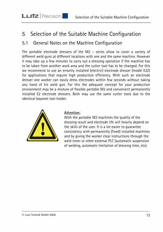
The portable electrode dressers of the M2 – series allow to cover a variety of different weld guns at different locations with one and the same machine. However it may take up a few minutes to carry out a dressing operation if the machine has to be taken from another work area and the cutter tool has to be changed. For this we recommend to use an errantly installed (electric) electrode dresser (model E2Z) for applications that require high production efficiency. With such an electrode dresser one worker can easily dress electrodes within few seconds without taking any hand of his weld gun. For this the adequate concept for your production environment may be a mixture of flexible portable M2 and convenient permanently installed E2 electrode dressers. Both may use the same cutter tools due to the identical bayonet tool holder.
Attention: With the portable M2 machines the quality of the dressing result and electrode life will heavily depend on the skills of the user. It is a lot easier to guarantee consistency with permanently (fixed) installed machines and by giving the worker clear instructions through the weld timer or other external PLC (automatic suspension of welding, automatic limitation of dressing time, etc).
13 © Lutz Technik GmbH 2006

Selection of the Suitable Machine Configuration
F i g . 04 – Po r t ab l e D r e s s e r M2
14 © Lutz Technik GmbH 2006
Selection of the Suitable Machine Configuration
5.2 Cutter Tools
The selection of the tools depends on
the specified electrode pairing (e.g. F16/F16).
the electrodes wear that result from the welding application.
The following are available
Tools with ONE exchangeable blade for the machining (Y-Blade). Deformations and contamination on the surface of the electrode are removed. However, owing to the extensive material removal, the electrode life is generally shorter than in the case of roughing tools.
Tools with FOUR cutting surfaces arranged at 90 degrees (Quattro-Blade). Deformation and the surface contamination are removed by RASPING. Maximum life of the electrodes can be achieved by the fine-tuning the removal of material. In case of increased electrode contamination, the removal capacity of the tool can be too low.
The milling cutter should be specified separately from the machine.
Please check our sales catalogue for information on available models, cutters and other accessories.
Order Example:
Portable dresser ref. 0.17.00.02A with cutter type Q5,8/4-5,8/4-30-A
15 © Lutz Technik GmbH 2006

Selection of the Suitable Machine Configuration
16 © Lutz Technik GmbH 2006

Selection of the Suitable Machine Configuration
F i g . 05 – S i ng l e -B l a de Cu t t e r T oo l
17 © Lutz Technik GmbH 2006

Selection of the Suitable Machine Configuration
18 © Lutz Technik GmbH 2006

Selection of the Suitable Machine Configuration
F i g . 06 – “Qua t t r o -B l a de ” Cu t t e r T oo l
19 © Lutz Technik GmbH 2006

Installation
6 Installation
6.1 General Instructions for Installation
Our devices are supplied in cardboard boxes and/or on palettes in such a way that there can be no damage and that transportation capacity and costs are exploited to an optimum extent. Therefore, generally, at the time of installation only the air supply has to be connected and the cutter tool has to be mounted.
6.2 Preparation of the Working Area
When preparing the working area make sure that
the cutters match the profiles of all electrode pairs that are going to be dressed.
the air supply is long enough to allow free movement during dressing operation.
The air hose must not inflict with other components such as weld guns, jigs and fixtures. All machine connections -cable, hoses and piping- should be laid in such a manner that they do not result in any stumbling points.
when laying cables and hoses, the specified bending radii must be adhered to. Abrasions can result in leaks. Twists in compressed air pipes reduce the performance of the electrode dresser.
20 © Lutz Technik GmbH 2006

Installation
6.3 Air Supply
The power characteristics and hence the milling result of pneumatic devices depend directly on the applied air pressure. Please note that
for safe operation, a flow pressure of at least 6 bar (higher air pressures should be throttled to maximum 10 bar) and an air volume of at least 10 liters/second are maintained.
only purified air is used (filter of 5µ!).
in all the feed pipes, a clear width of 10 mm may not be reduced. All pneumatic components such as filter regulators or shut off valves should be equipped with an air connection of at least G1/4”.
when using dirty or excessively small exhaust air silencers, there can be a back draft and hence, reduction in the performance.
6.4 Use with Several Guns
When using the portable electrode dresser for several weld guns we strongly recommend using a pneumatic QUICK CONNECTOR directly at the air inlet of the pneumatic motor. The air hose with the counter plug should be in a specially assigned pick up point close to the working area.
6.5 Low Pressure System
In the case a proportional valve is not available or a separate dressing program may not be implemented a Low Pressure System can added to the guns air supply.
The Lutz Low Pressure System (ref. 4.17.00.01) allows a safe selection of the correct gun force by the weld timer or the worker. The integrated pressure switch prevents weld failures because the worker may have forgotten to switch back to weld force after dressing.
21 © Lutz Technik GmbH 2006

Installation
F i g . 07 – Low P r e s su r e S y s t em ( r e f . 4 . 17 . 00 . 01 )
22 © Lutz Technik GmbH 2006

Installation
F i g . 08 – LPS Pneumat i c D i ag r am
23 © Lutz Technik GmbH 2006

Commissioning
7 Commissioning
7.1 Preparing the Welding Equipment (Model M2)
Similar to robotic applications an additional dressing program has to be implemented into the weld timer. The dressing program
may be chosen automatically by the welding timer after a certain number of welds have been done. Then a clear visual and/or caustic indication has to be given to the worker to dress the electrodes
or chosen manually by the worker
In both scenarios while in dressing mode
the weld current has to be switched off. Failure to do so will damage the portable dresser.
the gun force has to be reduced to a minimum that allows safe opening and closing of the gun.
Attention: To high gun force during dressing operation may cause damage and injuries! Current flow while dressing will destroy the cutter tool.
Dressing electrodes under too high closing force is physically difficult to achieve. Weld gun component such as the adapter’s internally tapered profile may be damaged.
24 © Lutz Technik GmbH 2006

Commissioning
7.2 Preparing the Welding Equipment (Model M2plus)
Prepare the welding equipment as described in 7.1. When dressing electrodes on an opened gun there is no need to reduce the closing force of the weld gun. It has to be assured the weld gun may not close accidentally.
7.3 Optimizing Welding Parameters
The maximum number of welds between each dressing operation is depended on the wear rate of the electrodes during welding. This figure will mostly be between 50 and 500 welds. Welding parameters and the use of electrode dressing has to be well balanced by a weld engineer. Not resetting a stepper curve after dressing may lead to holes burned into the panels or the electrodes being stuck to the panels. Leaving out a dressing operation will cause cold welding at some stage.
25 © Lutz Technik GmbH 2006

Usage
8 Usage Ensure that the electrode milling cutter has been installed and commissioned according to section 6 and 7.
Check if the electrodes are aligned collinearly to one another. Both electrodes have to be safely seated onto the taper. Leakage of water between the electrodes and the shanks indicate poor taper lock.
For adequate dressing results work according to the procedures stated thereafter. Certainly several routines such as
- initiating the dressing mode after maximum of welds is reached
- shut off weld current in dressing mode
- close weld gun at low force when weld gun’s fire button is activated
- open gun in dressing mode after few seconds thereafter
have to be implemented into the weld timers PLC. The use of the Low Pressure System may avoid the retrofit of a proportional valve and several of these software routines.
26 © Lutz Technik GmbH 2006
Usage
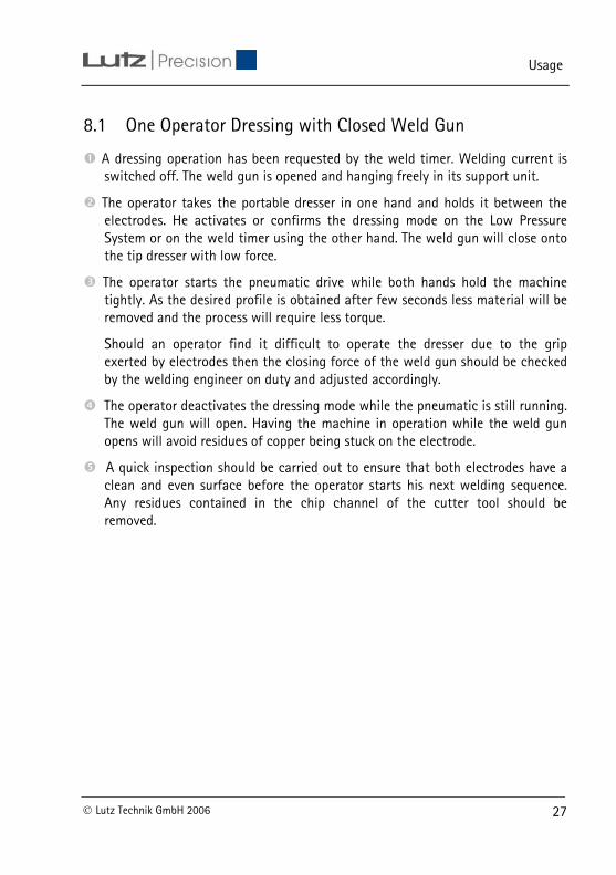
8.1 One Operator Dressing with Closed Weld Gun
A dressing operation has been requested by the weld timer. Welding current is switched off. The weld gun is opened and hanging freely in its support unit.
The operator takes the portable dresser in one hand and holds it between the electrodes. He activates or confirms the dressing mode on the Low Pressure System or on the weld timer using the other hand. The weld gun will close onto the tip dresser with low force.
The operator starts the pneumatic drive while both hands hold the machine tightly. As the desired profile is obtained after few seconds less material will be removed and the process will require less torque.
Should an operator find it difficult to operate the dresser due to the grip exerted by electrodes then the closing force of the weld gun should be checked by the welding engineer on duty and adjusted accordingly.
The operator deactivates the dressing mode while the pneumatic is still running. The weld gun will open. Having the machine in operation while the weld gun opens will avoid residues of copper being stuck on the electrode.
A quick inspection should be carried out to ensure that both electrodes have a clean and even surface before the operator starts his next welding sequence. Any residues contained in the chip channel of the cutter tool should be removed.
27 © Lutz Technik GmbH 2006
Usage
8.2 Two Operators Dressing with Closed Weld Gun
A dressing operation has been requested by the weld timer. Welding current is switched off. The weld gun is opened automatically while held by the operator.
A second (specialized tip-dress-) operater holds the portable dresser between the electrodes. The dressing mode will be activated / confirmed by the first operater using one of the triggers on the weld gun or a switch on the Low Pressure System. The weld gun will close onto the tip dresser with low force.
The tip-dress-operator activates the pneumatic drive while both hands hold the machine tightly. As the desired profile is obtained after few seconds less material will be removed and the process will require less torque.
The weld gun will open and the dressing mode is deactivated by the weld timer after a preset time while the pneumatic is still running. Having the machine in operation while the weld gun opens will avoid residues of copper being stuck on the electrode.
The tip-dress-operator does a quick inspection to ensure that both electrodes have a clean and even surface before the operator starts his next welding sequence.
The tip-dress-operator will then proceed to the next weld gun that requires his service.
28 © Lutz Technik GmbH 2006

Usage
8.3 One Operator Dressing with Open Weld Gun
A dressing operation has been requested by the weld timer. Welding current is switched off. The weld gun is opened and hanging freely in its support unit.
The operator takes the portable dresser M2plus with both hands. He docks the clamping mechanism into the small gap between the shank and the electrode. Then he pushes the dresser’s cutter firmly against one electrode by moving the clamps lever. The pneumatic drive will be started automatically as the lever is being pushed down further.
As the desired profile is obtained after few seconds less material will be removed and the process will require less torque. Releasing the clamps lever will stop the pneumatic drive.
The whole procedure has to be repeated for the second electrode.
A quick inspection should be carried out to ensure that both electrodes have a clean and even surface before the operator starts his next welding sequence. Any residues contained in the chip channel of the cutter tool should be removed.
29 © Lutz Technik GmbH 2006

Optimization
9 Optimization
9.1 Usage Parameters
Ensure that the electrode milling cutter has been installed and commissioned according to Section 6 and 7.
In the course of optimization, what is involved is that there should be a milling image of adequate quality for the respective welding job and that the life of the electrode must be increased by reduced material usage.
Satisfactory results can generally be obtained in the following value ranges
Tool Type Y-Blade Quattro-Blade
(1) Closing force during dressing [kN] 0.5 – 0.8 0.7 – 1.0
(2) Milling rotations in case of a new electrode or "start milling“
5 9
(3) Milling rotations in case of already milled electrode
5 6
* Values referred to electrode ø16mm, type F16 (ISO5821) and may vary with other profiles!
Parameters deviating from this are possible in exception cases, but there can be significant limitations in the milling results, the electrode life as well as increased wear of the tools and the equipment. In order to not endanger the warranty cover, in such special cases, you should consult us. To the extent possible, we will be happy to provide a corresponding written approval.
The starting value for the optimization can be assumed to be the average of the aforementioned settings:
Particularly when welding galvanized, high-strength plates, the electrodes are stressed to a great extent. Frequent electrode milling with minimized material
30 © Lutz Technik GmbH 2006

Optimization
removal increases the process safety over a constant electrode shape. At the same time, there are fewer welding expulsions, and reworking is reduced. Stepping of the welding current can often be done away with, and makes it possible to reduce energy costs.
9.2 Improving the Dressing Result
The milling image of a new electrode shows a possible mismatch in the programming of the welding robot. Inaccurate alignment can have a very adverse effect on the milling result, and more especially, the electrode life: In the case of an offset-milled electrode, the milling cutter reaches its cooling circuit too soon and the electrode collapses prematurely.
Position the electrode holder and optimize the milling process in such a way that
the active surface of both the electrodes is in their centre as far as possible. In doing so, use a new electrode for every new trial milling, since the result can get falsified by an electrode that has already been milled.
when milling a round electrode (Form F according to ISO), no radius is recognizable between the electrode active surface and its flank.
31 © Lutz Technik GmbH 2006

Optimization
Possible forms of the mismatch or offset, which generally appear as a combination, are shown below:
F i g . 09 – M i l l i ng Image s i n Ca se o f M i sma tch o r O f f s e t (Ax i s Gun / E l e c t r ode s – D r e s s e r s Ro ta t i ona l Ax i s )
32 © Lutz Technik GmbH 2006

Optimization
In the optimum case, the milling result will tally with the specifications of the data sheet for the relevant milling tool. Generally, however, certain variants in the active surface diameter and the active surface radius have to be accepted and taken into account. The greater the incline of the electrodes to one another plus the instability of the electrode holder, the greater is the variation.
33 © Lutz Technik GmbH 2006

Help in Case of Faults
10 Help in Case of Faults Before working on the machine, please read the safety
instructions in your own interest!
Document damage (type, time, location), to simplify the rectification of the causes for yourself and for others.
Cure the cause and not just the symptoms! If similar faults occur frequently in the same station, the underlying causes may be a deeper one (e.g. increased tool wear because of adhesives)
Fault Error source Measure (1) Cutter tool not
turning and no running noises can be heard
No air supply or low air pressure because of hose defect
Check step-wise the air supply and change the hose or fittings if necessary
No air supply or low air pressure because of defect in the dresser’s manual valve
Replace or repair pneumatic drive
Pneumatic drive’s silencer at air outlet clogged
Replace or clean silencer
(2) Cutter tool turning
but no removal or hardly any removal at the electrodes
Milling tool is damaged or blunt.
Check cutter tool. Replace whole unit or only blade.
Weld gun is not building up a closing force at all, or the closing force is too low.
Check the closing force and if required, set afresh.
34 © Lutz Technik GmbH 2006

Help in Case of Faults
Fault Error source Measure (3) Cutter tool not
turning, but running noises can be heard
The bayonet location receptacle is damaged.
The tool receptacle should be tested by unlocking and locking again. Check whether there is traction to the drive. In case of damage, the gear wheel with bayonet location receptacle should be replaced.
The carrier on the motor shaft is damaged.
Unplug air. Turn cutter by hand and check if pneumatic drive turns. If this is not the case, take the pneumatic drive off the gear box. Check and replace carrier if necessary.
The gearbox is damaged or the gear wheels are not in correct position.
Check gear wheels and ball bearings. Make sure all parts are correctly seated. In case one gear wheel is damaged, then also the other gear wheel should be replaced. Exchange ball bearings as well. In case of external damage to the cover plates, e.g. caused by closing the electrode holder on the gearbox, the complete gearbox unit must be changed.
35 © Lutz Technik GmbH 2006

Help in Case of Faults
Fault Error source Measure
(4) Milling insert gets regularly blocked; the electrode life is shortened.
Gun force during dressing operation too high.
Check the closing pressure and if required, set afresh.
Adhesive and sealing material residues
Check the milling cutter inserts regularly (electrode change) and if required, replace and then clean them.
The wrong tool type results in excessive material removal.
Check model and if required, replace it.
(5) Electrodes are
either not dressed at all even during the initial run of the device or milled too little.
Wrong or faulty milling insert Check the part and replace if required. Important factors such as the radi milled in the active surface area, should only be recorded with precision measurement devices. In case of doubt, you should adhere to the type designation and the description in the data sheets or consult Lutz Technik.
Cutting speed too low because the motor rating is too low or damage to the gearbox.
see (1) – (3)
Closing pressure of electrode holders is too low.
Increase the closing pressure in steps.
Milling time too short. Increase the milling time in steps.
Caution: Never clean QUATTRO-BLADE inserts with metal tools, since the blades can easily get damaged while tilting.
36 © Lutz Technik GmbH 2006

Help in Case of Faults
Fault Error source Measure (6) Electrodes do not
get dressed at all, or get dressed too little, during ongoing operation.
see (5) see (5)
Milling insert blocked. Clean milling insert. see (4)
Milling insert does not remove material because of oil residues.
Clean the milling insert with solvent.
Milling insert damaged because of welding current.
Replace part Ensure that while milling, no current is initiated even for a short time.
Blades in the milling insert worn.
Check the part and replace it.
Lamellas inside pneumatic drive are worn out or broken
Replace lamellas.
(7) Even though both
the electrodes are of the same type, their lives are different.
see (6) see (6)
Depending on the welding task, the electrodes are stressed to different levels. This can result e.g. from insufficient cooling or positioning errors in the holder.
37 © Lutz Technik GmbH 2006

Help in Case of Faults
Fault Error source Measure (8) Electrode active
surface is too small and/ or not round. Chatter marks are formed on the electrodes.
Wrong cutter tool Check part, replace if required.
A small burr forms in the middle of the electrode active surface.
Building-up (oscillations) of the cutter tool owing to unstable assembly and/or milling for an excessive time, in conjunction with asymmetric milling tools (Y-BLADE, turning plate).
Use self-centering QUATTRO-BLADE inserts. Shorten the milling time to the extent possible.
Electrodes are not correctly aligned.
Re-adjust electrode holder.
(9) Chips are not
removed completely.
Milling machine stops when the weld gun is still closed.
Ensure that the electrode dresser stops only after opening the electrode holder.
Use QUATTRO-BLADE insert.
38 © Lutz Technik GmbH 2006

Upkeep
11 Upkeep It is fundamental for the operational safety of the electrode milling machine that no significantly large material residues should be deposited in the chip chambers of the milling tool and in the exhaust – if present. Regular cleaning prevents faults, and in general, some machines, owing to grease deposits and adhesives in the environment, get dirty faster than others. Therefore, the following data is only for orientation. The conscientious maintenance technician is urged to check problem areas more frequently than others.
Provided that the installation is optimal and if there is an average level of contamination, we recommend:
Interval Assembly / part Measure (1) 1.000 milling
operations or monthly
Cutter tool
Cleaning the milling tool with a grease-dissolving cleaner (cold cleaning agent). Before inserting the tool, clean the bayonet location.
(2) 10.000 milling operations
Cutter tool Important: In the case of certain cutter types and special usage cases, e.g. lowered electrodes, the replacement may also be necessary much more frequently.
Cleaning and checking the milling tool. Replace in case of doubt. In the case of single-blade tools, replacement of the cutting plate is generally sufficient.
(3) quarter annually
Pneumatic drive, hoses, regulators and valves
Checking for air tightness. Tighten or replace if required.
(4) quarter annually
Pneumatic drive Clean and lubricate the pneumatic drive
(5) annually Complete unit Check the portable dresser, for excessive wear: ball bearings, bayonet holder. If required, replace and re-commission.
39 © Lutz Technik GmbH 2006

Upkeep
F i g . 10 – Po r t ab l e D r e s s e r M2p lu s – E xp l o s i on D raw ing
40 © Lutz Technik GmbH 2006

Upkeep
F i g . 11 – M2 Gea r Box – E xp l o s i on D ra w ing
41 © Lutz Technik GmbH 2006

Upkeep
F i g . 12 – M2p lu s C l a m p ing Un i t – E xp l o s i on D ra w ing
42 © Lutz Technik GmbH 2006
Reclamation
12 Reclamation The manufacturers accept no responsibility for any losses, consequential or otherwise arising from the ability or inability to use the equipment supplied.
The limit of the warranty is the repair or replacement of any faulty components directly attributable to manufacturing defects arising during the period of 12 months following purchase.
The warranty does not include damage resulting from incorrect operation of the unit.
In case of any damage or malfunction of our product we ask you to:
- Contact our sales service staff by phone or email.
- Add a copy of our delivery note, confirmation of order, invoice or your purchase order.
- Add a short description of the problem.
- We may only accept CIF return shipments.
43 © Lutz Technik GmbH 2006

Contact
13 Contact Europe: Lutz Technik GmbH
Hildachstrasse 12-14 D - 81245 München
Phone: +49 (0) 89 820 30 60 Fax: +49 (0) 89 820 30 659
North America: Lutz Precision Ltd. 368 Betty Street Windsor, ON N8S 3W8 Canada
Phone: +1 519 566 92 16 Fax: +1 866 362 59 88
South America: Lutz Técnica Brasil Ltda. Rua Irineu Vilella Veiga, 135 Salas 06 e 07, CEP 89.279-000 Bairro Centro – Guaramirim SC - Brasil
Phone: +55 47 373 26 59 Fax: +55 47 373 35 27
www.lutz-precision.com
44 © Lutz Technik GmbH 2006

Notes
14 Notes
…………………………………………………………………………………………………………………………………………………………………………………………………………………………………………………………………………………………………………………………………………………………………………………………………………………………………………………………………………………………………………………………………………………………………………………………………………………………………………………………………………………………………………………………………………………………………………………………………………………………………………………………………………………………………………………………………………………………………………………………………………………………………………………………………………………………………………………………………………………………………………………………………………………………………………………………………………………………………………………………………………………………………………………………………………………………………………………………………………………………………………………………………………………………………………………………………………………………………………………………………………………………………………………………………………………………………………………………………………………………………………………………………………………………
45 © Lutz Technik GmbH 2006