operating manual - multicluster-box 12
TRANSCRIPT

SUNNY ISLANDMULTICLUSTER BOX
MC-BOX-12-3-20-BE-en-14 | Version 1.4ENGLISH
Operating manualMULTICLUSTER-BOX 12

Legal Provisions SMA Solar Technology AG
Operating manualMC-BOX-12-3-20-BE-en-142
Legal ProvisionsThe information contained in these documents is the property of SMA Solar Technology AG. No part of this documentmay be reproduced, stored in a retrieval system, or transmitted, in any form or by any means, be it electronic,mechanical, photographic, magnetic or otherwise, without the prior written permission of SMA Solar Technology AG.Internal reproduction used solely for the purpose of product evaluation or other proper use is allowed and does notrequire prior approval.SMA Solar Technology AG makes no representations or warranties, express or implied, with respect to thisdocumentation or any of the equipment and/or software it may describe, including (with no limitation) any impliedwarranties of utility, merchantability, or fitness for any particular purpose. All such representations or warranties areexpressly disclaimed. Neither SMA Solar Technology AG nor its distributors or dealers shall be liable for any indirect,incidental, or consequential damages under any circumstances.The exclusion of implied warranties may not apply in all cases under some statutes, and thus the above exclusion maynot apply.Specifications are subject to change without notice. Every attempt has been made to make this document complete,accurate and up-to-date. Readers are cautioned, however, that product improvements and field usage experience maycause SMA Solar Technology AG to make changes to these specifications without advance notice, or per contractprovisions in those cases where a supply agreement requires advance notice. SMA Solar Technology AG shall not beresponsible for any damages, including indirect, incidental or consequential damages, caused by reliance on thematerial presented, including, but not limited to, omissions, typographical errors, arithmetical errors or listing errors inthe content material.
SMA WarrantyYou can download the current warranty conditions from the Internet at www.SMA-Solar.com.
TrademarksAll trademarks are recognized, even if not explicitly identified as such. Missing designations do not mean that aproduct or brand is not a registered trademark.
SMA Solar Technology AGSonnenallee 134266 NiestetalGermanyTel. +49 561 9522-0Fax +49 561 9522-100www.SMA.deEmail: [email protected]: 11/18/2019Copyright © 2019 SMA Solar Technology AG. All rights reserved.

Table of ContentsSMA Solar Technology AG
Operating manual 3MC-BOX-12-3-20-BE-en-14
Table of Contents1 Information on this Document..................................................................................................... 5
1.1 Validity ............................................................................................................................................................. 51.2 Target Group ................................................................................................................................................... 51.3 Levels of Warning Messages.......................................................................................................................... 51.4 Symbols in the Document................................................................................................................................ 51.5 Typographies in the Document ....................................................................................................................... 61.6 Designation in the document .......................................................................................................................... 61.7 Additional Information..................................................................................................................................... 6
2 Safety ............................................................................................................................................ 72.1 Intended Use.................................................................................................................................................... 72.2 IMPORTANT SAFETY INSTRUCTIONS......................................................................................................... 8
3 Scope of Delivery ......................................................................................................................... 10
4 Product Overview ........................................................................................................................ 114.1 Product Description.......................................................................................................................................... 114.2 Symbols on the Product................................................................................................................................... 124.3 Grounding in the Multicluster System............................................................................................................. 134.4 System Structure............................................................................................................................................... 14
5 Mounting....................................................................................................................................... 155.1 Requirements for Mounting............................................................................................................................. 155.2 Preparing the Mounting Location ................................................................................................................... 165.3 Transporting and Mounting the Product ........................................................................................................ 17
6 Electrical Connection .................................................................................................................... 196.1 Overview of the Connection Area.................................................................................................................. 19
6.1.1 Interior View ..................................................................................................................................................... 196.1.2 View from Below .............................................................................................................................................. 20
6.2 Installing the Multicluster-Box without Grid-Connect-Box.............................................................................. 216.3 Connecting the Generator .............................................................................................................................. 216.4 Utility Grid Connection.................................................................................................................................... 22
6.4.1 Utility Grid Connection Options...................................................................................................................... 226.4.2 Connecting the Grid-Connect-Box .................................................................................................................. 22
6.5 Connecting the Loads...................................................................................................................................... 236.6 Connecting the PV System .............................................................................................................................. 246.7 Connecting the Sunny Island .......................................................................................................................... 256.8 Grounding the Multicluster System................................................................................................................. 256.9 Connecting the Control Cables ...................................................................................................................... 26
6.9.1 Assignment of Spring-Cage Terminals ............................................................................................................ 266.9.2 Connecting the Control Cables of the Sunny Island Inverters....................................................................... 266.9.3 Connecting Supply Voltage for Grounding Contactor.................................................................................. 276.9.4 Connecting the Control Cables to the Grid-Connect-Box.............................................................................. 27
6.10 Connecting the Data Cable ............................................................................................................................ 28
7 Preparing for Commissioning ..................................................................................................... 29
8 Disconnect from voltage sources ................................................................................................ 30
9 Periodic Actions ............................................................................................................................ 319.1 Removing the Protective Cover ....................................................................................................................... 31

Table of Contents SMA Solar Technology AG
Operating manualMC-BOX-12-3-20-BE-en-144
9.2 Inserting Power and Control Cables .............................................................................................................. 329.3 Inserting Data Cables...................................................................................................................................... 339.4 Connecting Power Cables to Spring-Cage Terminals ................................................................................... 349.5 Connecting Control Cables to Spring-Cage Terminals ................................................................................. 359.6 Mounting the Protective Cover ....................................................................................................................... 36
10 Maintenance................................................................................................................................. 3810.1 Inspection of Residual-Current Devices .......................................................................................................... 3810.2 Checking the Surge Arresters ......................................................................................................................... 3910.3 General Maintenance Work .......................................................................................................................... 40
11 Decommissioning the Product ..................................................................................................... 42
12 Technical Data .............................................................................................................................. 43
13 Multicluster Technology Terms.................................................................................................... 48
14 Contact .......................................................................................................................................... 50

1 Information on this DocumentSMA Solar Technology AG
Operating manual 5MC-BOX-12-3-20-BE-en-14
1 Information on this Document1.1 ValidityThis document is valid for:
• MC-BOX-12.3-20 (Multicluster-Box 12)
1.2 Target GroupThe tasks described in this document must only be performed by qualified persons. Qualified persons must have thefollowing skills:
• Training in how to deal with the dangers and risks associated with installing, repairing and using electricaldevices, batteries and installations
• Training in the installation and commissioning of electrical devices and installations• Knowledge of all applicable laws, standards and directives• Knowledge of and compliance with this document and all safety information
1.3 Levels of Warning MessagesThe following levels of warning messages may occur when handling the product.
DANGER
Indicates a hazardous situation which, if not avoided, will result in death or serious injury.
WARNING
Indicates a hazardous situation which, if not avoided, could result in death or serious injury.
CAUTION
Indicates a hazardous situation which, if not avoided, could result in minor or moderate injury.
NOTICE
Indicates a situation which, if not avoided, can result in property damage.
1.4 Symbols in the DocumentSymbol Explanation
Information that is important for a specific topic or goal, but is not safety-relevant
☐ Indicates a requirement for meeting a specific goal
☑ Desired result
✖ A problem that might occur
Example

1 Information on this Document SMA Solar Technology AG
Operating manualMC-BOX-12-3-20-BE-en-146
1.5 Typographies in the DocumentTypography Use Example
bold • Messages• Terminals• Elements on a user interface• Elements to be selected• Elements to be entered
• Connect the insulated conductorsto the terminals X703:1 toX703:6.
• Enter 10 in the field Minutes.
> • Connects several elements to beselected
• Select Settings > Date.
[Button][Key]
• Button or key to be selected or pressed • Select [Enter].
# • Placeholder for variable components(e.g., parameter names)
• Parameter WCtlHz.Hz#
1.6 Designation in the documentComplete designation Designation in this document
Grid-Connect-Box 12 Grid-Connect-Box
Multicluster-Box 12 Multicluster-Box
Sunny Island 6.0H / 8.0H Sunny Island, battery inverter
1.7 Additional InformationFor more information, please go to www.SMA-Solar.com.
Title and information content Type of information
SUNNY ISLAND 4.0M / 6.0H / 8.0H Operating manual
GRID-CONNECT-BOX 12 Operating manual

2 SafetySMA Solar Technology AG
Operating manual 7MC-BOX-12-3-20-BE-en-14
2 Safety2.1 Intended UseThe Multicluster-Box is the main AC distribution board in a multicluster system. The multicluster system forms an AC gridand is made up of several three-phase clusters.The product is not suitable for supplying life-sustaining medical devices. A power outage must not lead to personalinjury.Do not exceed the maximum AC connection power of the Multicluster-Box. Cables with copper conductors must beused for the installation.The generator must always be connected directly to the Multicluster-Box.The utility grid may only be connected to the terminal provided for the generator on the Multicluster-Box under thefollowing conditions:
• Connecting the utility grid to the Multicluster-Box must be permitted in accordance with the local standards anddirectives.
• Connecting the utility grid to the Multicluster-Box must be agreed with the grid operator.• No generator may be installed in the multicluster system.
To connect the generator and the utility grid, it is necessary to install a Grid-Connect-Box between the utility grid andthe Multicluster-Box.The Multicluster-Box is designed for connection to TN-S, TN-C-S, and TT systems:
• If the multicluster system is using a generator as grid-forming source, the neutral point of the generator must begrounded (see Section 6.8, page 25).
• If the Multicluster-Box is used together with the Grid-Connect-Box, remember that the all-pole disconnection can bedeactivated on the Grid-Connect-Box (see operating manual of the Grid-Connect-Box). If the all-poledisconnection on the Grid-Connect-Box is deactivated, the utility grid must be configured as a TN-C-S system (seeSection 4.3, page 13).
• If the utility grid is connected directly to the Multicluster-Box, the neutral point of the utility grid must be grounded(see Section 6.8, page 25).
The Multicluster-Box must only be operated in conjunction with Sunny Island 6.0H (SI6.0H-13 / SI6.0H-12) or SunnyIsland 8.0H (SI8.0H-13 / SI8.0H-12). Always take the maximum AC connection power and the permitted invertercombinations into account.In terms of interference immunity, the product is suitable for EMC environment A, and in terms of EMC emissions, it issuitable for EMC environment B (as per IEC 61439-1:2011).The product is designed for indoor use only.Only operate the product at temperatures between −-25°C and +60°C.The Multicluster-Box is designed for use at altitudes of up to 2300 m above Mean Sea Level. If you would like to usethe Multicluster-Box at altitudes above 2300 m, contact Service (see Section 14, page 50).Use SMA products only in accordance with the information provided in the enclosed documentation and with thelocally applicable laws, regulations, standards and directives. Any other application may cause personal injury orproperty damage.Alterations to the SMA products, e.g., changes or modifications, are only permitted with the express written permissionof SMA Solar Technology AG. Unauthorized alterations will void guarantee and warranty claims and in most casesterminate the operating license. SMA Solar Technology AG shall not be held liable for any damage caused by suchchanges.Any use of the product other than that described in the Intended Use section does not qualify as the intended use.The enclosed documentation is an integral part of this product. Keep the documentation in a convenient, dry place forfuture reference and observe all instructions contained therein.

2 Safety SMA Solar Technology AG
Operating manualMC-BOX-12-3-20-BE-en-148
This document does not replace and is not intended to replace any local, state, provincial, federal or national laws,regulations or codes applicable to the installation, electrical safety and use of the product. SMA Solar Technology AGassumes no responsibility for the compliance or non-compliance with such laws or codes in connection with theinstallation of the product.The type label must remain permanently attached to the product.
2.2 IMPORTANT SAFETY INSTRUCTIONSSAVE THESE INSTRUCTIONSThis section contains safety information that must be observed at all times when working.The product has been designed and tested in accordance with international safety requirements. As with all electricalor electronical devices, there are residual risks despite careful construction. To prevent personal injury and propertydamage and to ensure long-term operation of the product, read this section carefully and observe all safetyinformation at all times.
DANGER
Danger to life due to electric shock when live components or cables are touchedHigh voltages are present in the conductive components or cables of the product. Touching live parts and cablesresults in death or lethal injuries due to electric shock.
• Do not touch non-insulated parts or cables.• Disconnect the product from voltage sources and make sure it cannot be reconnected before working on the
device.• Only disassemble the protective covers, if the product is disconnected from all voltage sources.• Wear suitable personal protective equipment for all work on the product.
CAUTION
Risk of injury if the product tips overThe product is heavy and may tip over if not properly fastened to the support surface. This can result in crushinginjuries.
• Upon installation, attach the product to the support surface.
CAUTION
Risk of burns due to hot componentsSome components and terminals inside the product can become hot during operation. Touching hot components orterminals can result in burn injuries.
• Wear suitable personal protective equipment for all work on the product.• Only operate the product with its protective cover mounted.• Prior to removing the protective cover, let the product cool down.

2 SafetySMA Solar Technology AG
Operating manual 9MC-BOX-12-3-20-BE-en-14
NOTICE
Damage to the product due to sand, dust and moisture ingressSand, dust and moisture penetration can damage the product and impair its functionality.
• Do not open the product during a dust storm or precipitation.• Close the product in case of interruption of work or after finishing work.• Only operate the product when it is closed.• Store the closed product in a dry and covered location. Observe storage conditions.
Effects of an emergency disconnectionEmergency disconnection on the battery inverter triggers the uncontrolled shutdown of the system and unsaveddata is lost.
• Only trip the emergency disconnection to avoid danger or consequential damage.• In the event of an emergency disconnection, always check whether any fuse elements in the product, such as
circuit breakers, have tripped.• If any fuse elements have tripped, reactivate these fuse elements.

3 Scope of Delivery SMA Solar Technology AG
Operating manualMC-BOX-12-3-20-BE-en-1410
3 Scope of DeliveryCheck the scope of delivery for completeness and any externally visible damage. Contact your distributor if the scopeof delivery is incomplete or damaged.
B DC
Main Cluster BoxMaster Main Cluster BoxSlave 1 Main Cluster BoxSlave 2
F J
SMA
A
HG
E
I
Figure 1: Components included in the scope of delivery
Position Quantity Designation
A 1 Multicluster-Box
B 1 Data cable for communication (10 m, black)
C 3 Data cable for measurement and control signals (10 m, red)
D 20 Strain relief with counter-sleeve (22 mm to 28 mm)
E 3 LV/HRC size 1 fuse link, 200 A
F 1 Set of non-woven adhesive labels for cable designation
G 4 Terminal incl. screws for connecting the protective conductors
H 3 Fuse link 1 A, tripping characteristics: gG
I 1 Fuse link 6 A, tripping characteristics: gG
J 1 Operating manual and circuitry overview

4 Product OverviewSMA Solar Technology AG
Operating manual 11MC-BOX-12-3-20-BE-en-14
4 Product Overview4.1 Product DescriptionThe Multicluster-Box is an SMA multicluster technology device for off-grid systems, battery-backup systems, and systemsfor increased self-consumption. The Multicluster-Box is a main AC distribution board to which you can connect up tofour clusters. Each three-phase cluster is made up of three DC-side, parallel-switched Sunny Island 6.0H / 8.0Hinverters with firmware version 3.5 or higher. Functions of the Multicluster-Box include:
• Main AC distribution board for Sunny Island inverters, one generator, one load, and one PV system• Load shedding• Automatic bypass and reverse current monitoring for the generator• Active anti-islanding
A
A
C
D
B
Figure 2: Multicluster-Box with cabinet door open
Position Designation
A Protective coverPrevents inadvertent contact with live components during operation and thus protects fromelectric shocks. When the product is in operation, the protective covers must always bemounted.
B Type labelThe type label clearly identifies the product. The type label must remain permanently at-tached to the product. You will find the following information on the type label:
• Device type (Model)• Serial number (Serial No. or S/N)• Date of manufacture• Device-specific characteristics

4 Product Overview SMA Solar Technology AG
Operating manualMC-BOX-12-3-20-BE-en-1412
Position Designation
C Residual-current deviceProtects against electric shock and is always used in addition to existing protective measuressuch as insulation or protective grounding. As soon as a dangerous touch voltage occurs, theresidual-current device switches the loads off at all poles. This is achieved by means of a sum-mation current transformer in the residual-current device which detects the electric currents inthe conductors L1, L2, L3, and N. In the normal operating state, the sum of these currentsequals zero. Under fault conditions a differential current is formed which trips the residual-cur-rent device.The residual-current device has a test button and a switch lever. The test button is used to testthe residual-current device. The switch lever is used to activate and deactivate (see Sec-tion 10.1, page 38).
D Circuit breakerProtects power cables of the connected inverters.
4.2 Symbols on the ProductSymbol Explanation
Beware of electrical voltageThe product operates at high voltages.
Beware of hot surfaceThe product can get hot during operation.
15 min Danger to life due to high voltages in the inverter; observe a waiting time of 15 minutesHigh voltages that can cause lethal electric shocks are present in the live components of theinverter.Prior to performing any work on the inverter, disconnect it from all voltage sources as de-scribed in this document.
Observe the documentationObserve all documentation supplied with the product.
Grounding conductorThis symbol indicates the position for connecting a grounding conductor.
WEEE designationDo not dispose of the product together with the household waste but in accordance with thedisposal regulations for electronic waste applicable at the installation site.
Degree of protection IP55The product is protected against interior dust deposits and water that is directed as a jetagainst the enclosure from all directions.

4 Product OverviewSMA Solar Technology AG
Operating manual 13MC-BOX-12-3-20-BE-en-14
Symbol Explanation
CE markingThe product complies with the requirements of the applicable EU directives.
RoHS
RoHS labelingThe product complies with the requirements of the applicable EU directives.
4.3 Grounding in the Multicluster SystemGrounding in the Multicluster-BoxThe grounding busbar X100 of the Multicluster-Box is always connected to the enclosure of the Multicluster-Box.All grounding conductors must be connected in accordance with the specifications of this operating manual (seeSection 6, page 19).
With TN-S, TN-C-S, and TT systems, the neutral conductor must be grounded for protection against indirect contact withlive components. The following conditions apply to grounding the neutral conductor in the multicluster system:
• If the multicluster system is using a generator as grid-forming source, the neutral point of the generator must begrounded.
• If the multicluster system is connected to the utility grid via a Grid-Connect-Box, the neutral point is grounded viathe utility grid when in parallel grid operation. However, in case of grid failure, the multicluster system mustdisconnect from the utility grid. For this disconnection, either only the line conductors are disconnected, or in caseof all-pole disconnection, the line conductors and the neutral conductor.
• If the utility grid is connected directly to the Multicluster-Box, the neutral point of the utility grid must be grounded.The installer bears sole responsibility for the grounding configuration and the grid disconnection required forinstances of grid failure. Directly connecting the utility grid to the Multicluster-Box must be permitted in accordancewith the local standards and directives and agreed with the grid operator.
With all-pole disconnection, the multicluster system with line conductors and neutral conductor are disconnected fromthe utility grid in the event of grid failure. This disconnection does not ground the neutral conductor in the grid of themulticluster system. Therefore, in multicluster systems with all-pole disconnection, the grounding contactor of theMulticluster-Box must ground the neutral conductor in the event of grid failure. The grounding contactor ensures thenecessary protection in case of indirect contact with live components. The grounding contactor is in fail-safe design.If the neutral conductor of the multicluster system is connected to the utility grid, no further grounding is permitted in theelectricity grid of the multicluster system. Therefore, if the multicluster system is connected to the utility grid or generator,the grounding contactor of the Multicluster-Box breaks the connection between neutral conductor and groundpotential.

4 Product Overview SMA Solar Technology AG
Operating manualMC-BOX-12-3-20-BE-en-1414
4.4 System Structure
SUNNY ISLAND
GRID CONNECT BOX
Load contactor
MULTICLUSTER BOX(Main AC distribution board)
PV main distribution box(not included in the
delivery)
BATTERY
Generator contactor GENERATOR
LOAD
PV MODULES
PV INVERTERS
UTILITY GRID
BATTERY FUSE
Figure 3: Circuitry principle of a multicluster system – example with Multicluster-Box

5 MountingSMA Solar Technology AG
Operating manual 15MC-BOX-12-3-20-BE-en-14
5 Mounting5.1 Requirements for Mounting
WARNING
Danger to life due to fire or explosionDespite careful construction, electrical devices can cause fires. This can result in death or serious injury.
• Do not mount the product in areas containing highly flammable materials or gases.• Do not mount the product in potentially explosive atmospheres.
Optimum mounting locationThe ambient temperature influences the tripping threshold of the circuit breakers for the connected batteryinverters. The higher the temperature, the earlier the circuit breakers will trip. At high ambient temperatures, thederating function of the battery inverters inhibits premature tripping of the circuit breakers.
• To ensure optimum operation, mount and install the Multicluster-Box and the battery inverters at the samelocation.
Mounting location:☐ A solid, flat support surface must be available for mounting.☐ The mounting location must be suitable for the weight and dimensions of the product (see Section 12 "Technical
Data", page 43).☐ The mounting location should be freely and safely accessible at all times without the need for any auxiliary
equipment (such as scaffolding or lifting platforms). Non-fulfillment of these criteria may restrict servicing.☐ The mounting location must not hinder access to disconnection devices.☐ All local requirements concerning minimum passage widths and escape routes must be observed.☐ All ambient conditions must be met (see Section 12, page 43).☐ The mounting location must be less than 2300 m above Mean Sea Level. If you would like to use the Multicluster-
Box at altitudes above 2300 m, contact Service (see Section 14, page 50).☐ The product may only be mounted in a permitted mounting position.
Permitted und prohibited mounting position:
Figure 4: Permitted and prohibited mounting positions

5 Mounting SMA Solar Technology AG
Operating manualMC-BOX-12-3-20-BE-en-1416
Recommended clearances:
200200200
Figure 5: Recommended clearances (dimensions in mm)
☐ There must be sufficient space at the mounting location to ensure compliance with the recommended clearances.☐ There must be a distance of at least 300 mm between the Multicluster-Box and the Grid-Connect-Box. This will
ensure adequate heat dissipation for each product.
Dimensions for Mounting:
30
0
1200
Ø 13
980
1075 62.5
26
36
0
Figure 6: Outside base measurements and dimensions of the drill holes (dimensions in mm)
5.2 Preparing the Mounting LocationWARNING
Danger to life due to fire or explosion if mounted at an unsuitable locationMounting the product in areas with a high fire hazard can result in fire. This can result in death or serious injury.
• Do not install the product on flammable construction materials.• Do not mount the product in areas containing highly flammable materials.• Do not mount the product in potentially explosive atmospheres.
Additionally required mounting material (not included in the scope of delivery):☐ 4 suitable screw anchors for attaching the product
Procedure:1. On the support surface, mark the positions of the four drill holes for attaching the base (see Section 5.1,
page 15).2. Drill holes at the marked positions.3. Use screw anchors that are suitable for the support surface.

5 MountingSMA Solar Technology AG
Operating manual 17MC-BOX-12-3-20-BE-en-14
5.3 Transporting and Mounting the ProductWARNING
Danger to life if raised or suspended loads tip over, fall or swayVibrations or careless or hasty lifting and transportation may cause the product to tip over or fall. This can result indeath or serious injury.
• Always transport the product as close to the floor as possible.• All means of transport and auxiliary equipment used must be designed for the weight of the product. Weight:
228 kg.• Always transport and lift the product upright.• Always maintain a sufficient safety distance from the product during transport.• Take into account the center of gravity of the product. The center of gravity is approximately in the center of the
cabinet.• Wear suitable personal protective equipment for all work on the product.
NOTICE
Damage to the product due to sand, dust and moisture ingress after setting down onunsuitable surfaceSetting the product down on an unsecured or uneven surface may cause the product to warp and allow sand, dustand moisture to enter the product. Sand, dust and moisture penetration can damage the product and impair itsfunctionality.
• Never set the product down on an unsecured or uneven surface.
Overview of transport options:The product is delivered on a Euro pallet. You can use the following means of transport to lift the product off the Europallet:
• Forklift• Crane with suitable fork
Additionally required mounting material (not included in the scope of delivery):☐ 4 suitable screws to attach the product to the support surface
Procedure:1. Remove all fastening screws from the kick plates at the front and rear (TX 30).2. Remove kick plates.
3. Retain the kick plates and the fastening screws for later use.4. Slide a suitable means of transport under the product.5. Transport the product to the mounting location using a suitable transport lock.
5 Mounting SMA Solar Technology AG
Operating manualMC-BOX-12-3-20-BE-en-1418
6. CAUTION
Risk of injury if the Multicluster-Box tips overThe Multicluster-Box is heavy and may tip over if not properly fastened to the support surface. This can result incrushing injuries.
• Attach the product to the support surface using four suitable screws.

6 Electrical ConnectionSMA Solar Technology AG
Operating manual 19MC-BOX-12-3-20-BE-en-14
6 Electrical Connection6.1 Overview of the Connection Area
6.1.1 Interior View
KLMN
A B
D
F
H
I
J
O
P
E
G
C
Figure 7: Components and terminals inside the Multicluster-Box
Position Designation
A Fuse switch-disconnector F101 for LV/HRC size 1 fuse links of the generator terminal
B Fuse switch-disconnector F102 for LV/HRC size 1 fuse links of the load terminal
C De-energized surge arrester
D Residual-current device of the Sunny Island inverters
E Circuit breakers for protecting the power cables of the Sunny Island inverters
F Spring-cage terminals X105 for connecting the power cables of the Sunny Island inverters
G Grounding contactor

6 Electrical Connection SMA Solar Technology AG
Operating manualMC-BOX-12-3-20-BE-en-1420
Position Designation
H Spring-cage terminals X106 to X113 for connecting the control cables of the Sunny Island invert-ers, battery fuse and Grid-Connect-Box
I Grounding busbar X100 for connecting the grounding conductors of the generator, the loads, andthe PV system as well as to connect the Multicluster-Box to the equipotential bondingIf the Grid-Connect-Box is installed, the corresponding grounding conductor is also connected here.When connecting the utility grid directly to the Multicluster-Box, the grounding conductor is alsoconnected here (see Section 6.4.1, page 22).
J Cable support rail
K Terminal X104 with spring-cage terminals L1, L2, L3 and N to connect the line conductors and theneutral conductor of the PV system
L Terminal X103 with spring-cage terminals L1, L2, L3 and N to connect the line conductors and theneutral conductor of the main distribution for loads
M Terminal X102 with spring-cage terminals L1, L2, L3 and N to connect the line conductors and theneutral conductor of the generatorWhen connecting the utility grid directly to the Multicluster-Box, the line conductors are also con-nected here (see Section 6.4.1, page 22).
N Terminal X101 with spring-cage terminals L1, L2, L3 and N to connect the line conductors and theneutral conductor of the Grid-Connect-BoxIf only the Multicluster-Box is installed, these terminals are not connected.
O SIBUCTRL with RJ45 jacks for connecting the data cables
P Fuses to protect the internal cabling
6.1.2 View from Below
BA
Figure 8: Enclosure openings in the bottom of the Multicluster-Box
Position Designation
A Base plate with membranes for inserting the power cables
B Two-part cable feed-through for inserting the data cables

6 Electrical ConnectionSMA Solar Technology AG
Operating manual 21MC-BOX-12-3-20-BE-en-14
6.2 Installing the Multicluster-Box without Grid-Connect-BoxIf the Multicluster-Box is installed without Grid-Connect-Box, the terminals of the grounding contactor and the generatorcontactor must be equipped with a jumper wire.
X110 X111X106 X107
+ _
DCDC
1 2 3 4 1 2 1 2 54 63 3 4 7651 2 8 9 10 11 12 13 1
A B
Figure 9: Overview of the provided jumper wires when installing the Multicluster-Box without Grid-Connect-Box
Position
A Position of the jumper wire for blocking the grounding contactor
B Position of the jumper wire for blocking the generator contactor
Procedure:1. Short-circuit X110:1 and X110:2 with a jumper wire to block the grounding contactor.2. Short-circuit X111:6 and X111:7 with a jumper wire to block the generator contactor.
6.3 Connecting the GeneratorYou can connect a three-phase generator to the Multicluster-Box. The line conductors are routed via fuse switch-disconnectors in the Multicluster-Box. LV/HRC size 1 fuse links 200 A are installed in the fuse switch-disconnector bydefault.
Generator output fuse influences dimensioning of the PV system power cablesRemember that the size of the generator output fuse affects the dimensioning of the PV system cable (seeSection 6.6, page 24).
Cable requirements:☐ Conductor material: copper☐ Conductor cross-section: 50 mm² to 150 mm²☐ The power cables must be ground-fault and short-circuit protected.☐ The AC conductors and DC conductors must always be routed in separate cables.
Procedure:1. Insert the power cables into the Multicluster-Box (see Section 9.2, page 32).2. Connect the grounding conductor to the grounding busbar
(AF 17, torque: 15 Nm). To do this, use the screw terminalincluded in the scope of delivery.

6 Electrical Connection SMA Solar Technology AG
Operating manualMC-BOX-12-3-20-BE-en-1422
3. Connect the neutral conductor to the spring-cage terminal N at terminal X102:4 (see Section 9.4, page 34).4. Connect the line conductors to the spring-cage terminals L1, L2, and L3 at the terminals X102:1 to X102:3.5. Ensure that a right-hand rotating magnetic field is present at the generator terminal.6. Provide for strain relief of the power cables by attaching them to the appropriate cable support rail. Use the strain
reliefs and counter-sleeves provided.7. According to the type of cable routing and the installation conditions, determine the required fuse link for the fuse
switch-disconnector and insert it into the fuse switch-disconnector F101.
6.4 Utility Grid Connection
6.4.1 Utility Grid Connection OptionsYou can connect the utility grid in the following ways:
• Utility grid connection via Grid-Connect-Box• Utility grid connection directly to the Multicluster-Box
The following conditions must be observed when connecting the utility grid.
Utility grid connection via Grid-Connect-BoxIf the VDE-AR-N 4105 rule does not apply to the utility grid and a generator has to be connected in addition to theutility grid, a Grid-Connect-Box must be installed between the utility grid and the Multicluster-Box (see Section 6.4.2,page 22).
Utility grid connection directly to the Multicluster-BoxFor direct connection of the utility grid to the Multicluster-Box, the following requirements must be fulfilled:
• The VDE-AR-N 4105 rule must not apply to the utility grid.• Directly connecting the utility grid to the Multicluster-Box must be permitted in accordance with the local standards
and directives and agreed with the grid operator.• If the utility grid is directly connected to the Multicluster-Box, no generator is to be installed in the multicluster
system.To connect the utility grid directly to the Multicluster-Box, terminal X102 of the generator is provided (seeSection 6.1.1, page 19). When connecting the utility grid directly to the Multicluster-Box, proceed as described belowfor the generator (see Section 6.3, page 21).
6.4.2 Connecting the Grid-Connect-BoxThe grid terminal output fuse influences dimensioning of the PV system power cablesRemember that the size of the grid fuse affects the dimensioning of the PV system cable (see Section 6.6,page 24).
Requirements:☐ The Grid-Connect-Box must be properly installed (see operating manual of the Grid-Connect-Box).
Cable requirements:☐ Conductor material: copper☐ Conductor cross-section: 50 mm² to 150 mm²☐ The power cables must be ground-fault and short-circuit protected.☐ The AC conductors and DC conductors must always be routed in separate cables.
Procedure:1. Insert the power cables into the Multicluster-Box (see Section 9.2, page 32).

6 Electrical ConnectionSMA Solar Technology AG
Operating manual 23MC-BOX-12-3-20-BE-en-14
2. Connect the grounding conductor to the grounding busbar(AF 17, torque: 15 Nm). To do this, use the screw terminalincluded in the scope of delivery.
3. Connect the grounding conductor to the grounding busbar (AF 17, torque: 15 Nm). To do this, use the screwterminal included in the scope of delivery.
4. Connect the line conductors to the spring-cage terminals L1, L2, and L3 at the terminals X101:1 to X101:3 (seeSection 9.4, page 34).
5. Ensure that a right-hand rotating magnetic field is present at the terminal of the Grid-Connect-Box.6. Provide for strain relief of the power cables by attaching them to the appropriate cable support rail. Use the strain
reliefs and counter-sleeves provided.
6.5 Connecting the LoadsThe line conductors L1, L2, and L3 are routed via a fuse switch-disconnector in the Multicluster-Box. LV/HRC size 1 fuselinks 200 A are installed in the fuse switch-disconnector by default.
Cable protectionThe Multicluster-Box is not a substitute for the load distribution board.
• Between the Multicluster-Box and the loads, you must install a distribution board with circuit breakers toprotect and isolate the loads, as well as a residual-current device.
• Adhere to all standards and directives for the installation of electrical devices and systems applicable at theinstallation location.
Cable requirements:☐ Conductor material: copper☐ Conductor cross-section: 50 mm² to 150 mm²☐ The power cables must be ground-fault and short-circuit protected.☐ The AC conductors and DC conductors must always be routed in separate cables.
Procedure:1. Insert the power cables into the Multicluster-Box (see Section 9.2, page 32).2. Connect the grounding conductor to the grounding busbar
(AF 17, torque: 15 Nm). To do this, use the screw terminalincluded in the scope of delivery.
3. Connect the neutral conductor to the spring-cage terminal N at terminal X103:4 (see Section 9.4, page 34).4. Connect the line conductors to the spring-cage terminals L1, L2, and L3 at the terminals X103:1 to X103:3.5. Ensure that a right-hand rotating magnetic field is present at the load terminal.6. Provide for strain relief of the power cables by attaching them to the appropriate cable support rail. Use the strain
reliefs and counter-sleeves provided.7. According to the type of cable routing and the installation conditions, determine the required fuse link for the fuse
switch-disconnector and insert it into the fuse switch-disconnector F102.

6 Electrical Connection SMA Solar Technology AG
Operating manualMC-BOX-12-3-20-BE-en-1424
6.6 Connecting the PV SystemConnection of other energy sourcesInstead of a PV system, you can connect other energy sources (e.g. small wind turbine systems) to the Multicluster-Box.
Cable protectionThe Multicluster-Box does not take the place of the distribution board of the PV system (PV main distributionboard).
• Install a circuit breaker and, if necessary, a residual-current device between the Multicluster-Box and the PVsystem for protection and disconnection purposes.
• Adhere to all standards and directives for the installation of electrical devices and systems applicable at theinstallation location.
Cable dimensioning:In the event of a short circuit in the PV system cable, short-circuit currents arising in the generator or Grid-Connect-Boxwill flow via the unprotected cable between the Multicluster-Box and main PV distribution.
• Size the cables to match the fusing of the generator or the Grid-Connect-Box.When planning the short-circuit protection of cables, the PV inverters and Sunny Island inverters may be disregarded,as their construction precludes any danger to power cables in case of short circuits.
Cable requirements:☐ Conductor material: copper☐ Conductor cross-section: 50 mm² to 150 mm²☐ The power cables must be ground-fault and short-circuit protected.☐ The AC conductors and DC conductors must always be routed in separate cables.
Procedure:1. Insert the power cables into the Multicluster-Box (see Section 9.2, page 32).2. Connect the grounding conductor to the grounding busbar
(AF 17, torque: 15 Nm). To do this, use the screw terminalincluded in the scope of delivery.
3. Connect the neutral conductor to the spring-cage terminal N at terminal X104:4 (see Section 9.4, page 34).4. Connect the line conductors to the spring-cage terminals L1, L2 and L3 at the terminals X104:1 to X104:3.5. Provide for strain relief of the power cables by attaching them to the appropriate cable support rail. Use the strain
reliefs and counter-sleeves provided.

6 Electrical ConnectionSMA Solar Technology AG
Operating manual 25MC-BOX-12-3-20-BE-en-14
6.7 Connecting the Sunny Island
1 2 3 7 8 94 5 6 1 2 3 7 8 94 5 6 1 2 3 7 8 94 5 6 1 2 3 7 8 94 5 6
L1 L2 L3 N PE
Main Cluster
L1 L2 L3 N PE
Extension Cluster 1
L1 L2 L3 N PE
Extension Cluster 2
L1 L2 L3 N PE
Extension Cluster 3
A B C D
Figure 10: Overview of the spring-cage terminals for connecting the power cables of the Sunny Island inverters
Position Explanation
A Terminal for the power cables of the main cluster
B Terminal for the power cables of extension cluster 1
C Terminal for the power cables of extension cluster 2
D Terminal for the power cables of extension cluster 3
Fusing of the Sunny Island invertersThe power cables of each Sunny Island inverter are fused with a 40 A circuit breaker inside the Multicluster-Box.
Cable requirements:☐ Conductor material: Copper☐ The AC conductors and DC conductors must always be routed in separate cables.☐ Conductor cross-section: 0.5 mm² to 10 mm²
Procedure:1. Insert the power cables into the Multicluster-Box (see Section 9.2, page 32).2. Connect the line conductors, the neutral conductors and the grounding conductors of all Sunny Island inverters to
the spring-cage terminals X105 for the Sunny Island inverters (see Section 9.4, page 34).
6.8 Grounding the Multicluster SystemThe neutral conductors inside the Multicluster-Box are not connected to the grounding conductor by default. To ensuresafe operation of the multicluster system, you must perform the following action prior to commissioning:
Cable requirements:☐ Conductor material: copper☐ Conductor cross-section: 16 mm² to 120 mm²☐ The AC conductors and DC conductors must always be routed in separate cables.☐ The grounding of the system must be designed in accordance with the national standards and directives and is the
responsibility of the installer.

6 Electrical Connection SMA Solar Technology AG
Operating manualMC-BOX-12-3-20-BE-en-1426
Procedure:1. If connecting a generator to the multicluster system, the neutral point of the generator must be grounded. All
standards and directives applicable to the installation site must be observed.2. If the utility grid is only connected to the multicluster system, the neutral point of the utility grid must be grounded.
All standards and directives applicable to the installation site must be observed.
6.9 Connecting the Control Cables
6.9.1 Assignment of Spring-Cage Terminals
X110 X111X106 X107 X112 X113
+ _
DCDC
1 2 3 4 1 2 1 2 54 63 3 4 7651 2 8 9 10 11 12 13 1 2 3 4 5 76 8 9 10 1 2 3 4
A B C D E F
Figure 11: Overview of spring-cage terminals for connecting the control cables
Position Designation Description
A X106 Control voltage of the Sunny Island main cluster
B X107 Connect the supply voltage of the grounding contactor, e.g. of the battery fuse(DC)
C X110 Connection of control cables from Grid-Connect-Box (DC)
D X111 Connection of control cables from Grid-Connect-Box (AC)
E X112 Connection of control cables to the terminal ExtVtg of each Sunny Island in-verter in the main cluster (AC)Connection of control cables to the terminals Relay1 C and Relay1 NC at themaster of the main cluster (AC)
F X113 Connection of control cables to the master of the main cluster: terminals BatVt-gOut+, DigIn+, Relay2 NO, and Relay2 C (DC)
6.9.2 Connecting the Control Cables of the Sunny Island InvertersThe Sunny Island inverters of the main cluster must be connected to the Multicluster-Box via several control cables.These control cables transmit measurement and control signals between the Sunny Island inverters of the main clusterand the Multicluster-Box.
Cable requirements:☐ Conductor material: copper☐ Conductor cross-section: 0.75 mm² to 2.5 mm²☐ The AC conductors and DC conductors must always be routed in separate cables.

6 Electrical ConnectionSMA Solar Technology AG
Operating manual 27MC-BOX-12-3-20-BE-en-14
Procedure:1. Insert the control cables into the Multicluster-Box (see Section 9.2, page 32).2. Connect the cables to the spring-cage terminals X106, X112, and X113 (see Section 9.5, page 35):
• X106: control voltage of the main cluster• X112: control cables from Sunny Island 1 of the main cluster• X113: control cables from Sunny Island 2 of the main cluster
6.9.3 Connecting Supply Voltage for Grounding ContactorThe grounding contactor Q109 of the Multicluster-Box must be connected to an external DC voltage of 48 V. Theexternal DC voltage can be tapped from the battery fuse or the terminal BatVtgOut of a Sunny Island inverter.
Requirements:☐ A battery fuse must be installed or an unoccupied BatVtgOut terminal must be available at a Sunny Island
inverter☐ Maximum current load at the terminal BatVtgOut: 600 mA
Cable requirements:☐ Conductor material: copper☐ Conductor cross-section: 0.75 mm² to 2.5 mm²☐ The AC conductors and DC conductors must always be routed in separate cables.
Procedure:1. Insert the control cables into the Multicluster-Box (see Section 9.2, page 32).2. Connect the cables to the spring-cage terminals X107 (see Section 9.5, page 35). Make sure that the poling of
the terminals is correct.
6.9.4 Connecting the Control Cables to the Grid-Connect-BoxGround connection at terminals X110 and X111If the control cable between the Multicluster-Box and Grid-Connect-Box contains a grounding conductor, thegrounding conductor terminal must not be connected on both sides.
Cable requirements:☐ Conductor material: copper☐ Conductor cross-section: 0.75 mm² to 2.5 mm²☐ The AC conductors and DC conductors must always be routed in separate cables.
Procedure:1. Insert the control cables into the Multicluster-Box (see Section 9.2, page 32).2. Connect the cables to the spring-cage terminals X110 and X111 (see Section 9.5, page 35):
• X110:1 and X110:2: block of grounding contactor of Multicluster-Box• X110:4 and X110:5: feedback from AC contactor of Grid-Connect-Box• X111:1 to X111:4: voltage measurement of Grid-Connect-Box• X111:6 and X111:7: block of generator contactor of Multicluster-Box• X111:8 and X111:9: block of AC contactor of Grid-Connect-Box

6 Electrical Connection SMA Solar Technology AG
Operating manualMC-BOX-12-3-20-BE-en-1428
6.10 Connecting the Data CableThe data cables for measurement signals and communication are connected on the SIBUCTRL
Co
mS
yncT
nC
om
Syn
cOut
Sl v
2/L
3B
ack
upV
tgC
urS
l v1
/L2
Ba
ckup
Vtg
Cur
Mst
r/L1
Ba
ckup
Vtg
Cur
A
B
Figure 12: Overview of the connection area in the SIBUCTRL
Position Designation
A Jacks for communication (ComSyncIn, ComSyncOut)
B Jacks for measurement signals (Mstr/L1 Backup, Slv1/L2 BackupVtgCur, Slv2/L3 BackupVt-gCur)
Requirements:☐ The total length of the communication bus must not exceed 30 m. Keep in mind that the communication bus can
connect several nodes.☐ Make sure that the data cables are always routed separately from the power cables.
Procedure:1. Insert the data cables into the Multicluster-Box (see Section 9.3, page 33).2. Connect the data cables for measurement signals (red):
• for the master of the main cluster to jack Mstr/L1 BackupVtgCur (X30)• for slave 1 of the main cluster to jack Slv1/L2 BackupVtgCur (X31)• for slave 2 of the main cluster to jack Slv2/L3 BackupVtgCur (X32)
3. Connect the data cable for communication between the Sunny Island inverters and the Multicluster-Box (black) tojack ComSyncIn.
4. Connect the other end of the data cable to jack ComSyncIn of a Sunny Island inverter in the main cluster. Sinceall Sunny Island inverters of the main cluster (master and slaves) are interconnected via a communication bus, theMulticluster-Box can be connected to a slave or to the master of the main cluster (see operating manual of theSunny Island).
5. Ensure that the terminator is plugged into the jack ComSyncOut.

7 Preparing for CommissioningSMA Solar Technology AG
Operating manual 29MC-BOX-12-3-20-BE-en-14
7 Preparing for CommissioningLoad shedding in the first two operating hoursThe state of charge (SOC) recorded by battery management and the available battery capacity (SOH) willdeviate strongly from the actual values of SOC and SOH for a newly connected battery. During operation, thevalues recorded by battery management will gradually approach the real values. In the first two operating hourswith the new battery, these deviations can lead to load shedding and corresponding messages. These messageswill be displayed on the Sunny Island user interface.
Requirements:☐ If the Multicluster-Box is installed without Grid-Connect-Box, the terminals of the grounding contactor and the
generator contactor must be equipped with a jumper wire (see Section 6.2, page 21).☐ In a multicluster system with Grid-Connect-Box: all preparations for commissioning at the Grid-Connect-Box must
have been completed (see operating manual of the Multicluster-Box and operating manual of the Grid-Connect-Box).
☐ The multicluster system must be grounded outside the Multicluster-Box on the generator side or via the Grid-Connect-Box (see Section 6.8, page 25).
☐ The Multicluster-Box must be correctly mounted (see Section 5, page 15).☐ All cables must be correctly connected (see Section 6, page 19).☐ All cables must be tightly enclosed by a membrane or cable feed-through in the floor of the Multicluster-Box.☐ All power cables must be secured inside or outside the Multicluster-Box.☐ The floor of the Multicluster-Box must be closed with the base plates (see Section 9.2, page 32). All seals at the
base plates must be correctly positioned.
Procedure:1. Ensure that the power cables are secured with a strain relief.2. Insert the kick plates and attach with the fastening screws (TX 30, torque: 12 Nm).3. Mount the protective cover (see Section 9.6, page 36).4. Close Multicluster-Box.5. Commission the multicluster system (see documentation of the Sunny Island).6. In order to receive service assignments for the multicluster system, all system data must be recorded in the
information sheet for Sunny Island systems and made available to Service. To do this, access the information sheetat www.SMA-Solar.com.

8 Disconnect from voltage sources SMA Solar Technology AG
Operating manualMC-BOX-12-3-20-BE-en-1430
8 Disconnect from voltage sourcesCAUTION
Risk of burns due to hot componentsSome components and terminals inside the product can become hot during operation. Touching hot components orterminals can result in burn injuries.
• Wear suitable personal protective equipment for all work on the product.• Only operate the product with its protective cover mounted.• Prior to removing the protective cover, let the product cool down.
1. Switch off all loads.2. Stop the multicluster system on the master of the main cluster (see operating manual of the Sunny Island).3. Switch off all Sunny Island inverters (see the Sunny Island operating manual).4. Disconnect the PV main distribution board from voltage sources and secure against reconnection.5. Shut down the generator and secure against reconnection.6. If a Grid-Connect-Box is present, switch off all circuit breakers and residual-current devices in the Grid-Connect-
Box and disconnect the AC voltage supply at the grid-connection point.7. Open Multicluster-Box.8. In the Multicluster-Box, open all circuit breakers of the Sunny Island inverters.9. Prior to removing the protective cover, wait 15 minutes until the capacitors have discharged.
10. Remove the protective cover (see Section 9.1, page 31).11. Ensure that no voltage is present at all terminals of the Multicluster-Box.12. Ground the PV main distribution board outside the Multicluster-Box and short-circuit.13. Ground the generator outside the Multicluster-Box and short-circuit.14. Cover and isolate any adjacent live components.

9 Periodic ActionsSMA Solar Technology AG
Operating manual 31MC-BOX-12-3-20-BE-en-14
9 Periodic Actions9.1 Removing the Protective Cover
DANGER
Danger to life due to electric shock when live components or cables are touchedHigh voltages are present in the conductive components or cables of the product. Touching live parts and cablesresults in death or lethal injuries due to electric shock.
• Do not touch non-insulated parts or cables.• Disconnect the product from voltage sources and make sure it cannot be reconnected before working on the
device.• Only disassemble the protective covers, if the product is disconnected from all voltage sources.• Wear suitable personal protective equipment for all work on the product.
CAUTION
Risk of burns due to hot componentsSome components and terminals inside the product can become hot during operation. Touching hot components orterminals can result in burn injuries.
• Wear suitable personal protective equipment for all work on the product.• Only operate the product with its protective cover mounted.• Prior to removing the protective cover, let the product cool down.
Procedure:1. Release all fastening screws in the protective cover (TX 30).
9 Periodic Actions SMA Solar Technology AG
Operating manualMC-BOX-12-3-20-BE-en-1432
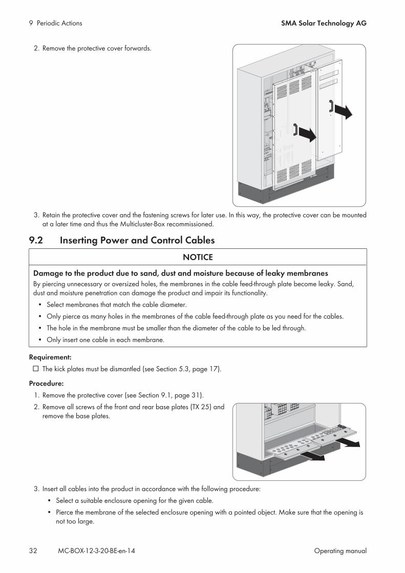
2. Remove the protective cover forwards.
3. Retain the protective cover and the fastening screws for later use. In this way, the protective cover can be mountedat a later time and thus the Multicluster-Box recommissioned.
9.2 Inserting Power and Control CablesNOTICE
Damage to the product due to sand, dust and moisture because of leaky membranesBy piercing unnecessary or oversized holes, the membranes in the cable feed-through plate become leaky. Sand,dust and moisture penetration can damage the product and impair its functionality.
• Select membranes that match the cable diameter.• Only pierce as many holes in the membranes of the cable feed-through plate as you need for the cables.• The hole in the membrane must be smaller than the diameter of the cable to be led through.• Only insert one cable in each membrane.
Requirement:☐ The kick plates must be dismantled (see Section 5.3, page 17).
Procedure:1. Remove the protective cover (see Section 9.1, page 31).2. Remove all screws of the front and rear base plates (TX 25) and
remove the base plates.
3. Insert all cables into the product in accordance with the following procedure:• Select a suitable enclosure opening for the given cable.• Pierce the membrane of the selected enclosure opening with a pointed object. Make sure that the opening is
not too large.

9 Periodic ActionsSMA Solar Technology AG
Operating manual 33MC-BOX-12-3-20-BE-en-14
• Insert each cable through the membrane of the selected enclosure opening into the Multicluster-Box. Ensurethat the cable is tightly enclosed by the membrane.
• Strip the insulation of each cable .
Cable typ Stripping length
Power cable 40 mm
Control cable 20 mm
4. Ensure that the seal at the edge of the base plate is firmly attached.5. Insert the base plates and tighten all screws of the base plate (TX 25 screwdriver, torque: 9 Nm).
9.3 Inserting Data CablesSeparate wiring of data and power cablesIf data cables are wired near power cables, coupling interference signals can occur under unfavorableconditions.
• Make sure that the data cables are always routed separately from the power cables.
Procedure:1. Loosen the screws of the mounting plate of the two-part cable
feed-through inside the Multicluster-Box.
2. Remove the mounting plate and set it aside.
3. Remove the cable feed-through from the enclosure.
4. Loosen the screws of the two-part cable feed-through and removethe half without the T-shaped fastening pieces.
1
2

9 Periodic Actions SMA Solar Technology AG
Operating manualMC-BOX-12-3-20-BE-en-1434
5. Lay the data cables into the half with the T-shaped fasteningpieces, and secure with cable ties. Ensure sufficient cable lengthfrom the cable feed-through to the desired connection point.
6. Screw the two halves back together. Fasten screws hand-tight. The data cables and placeholders (plastic inserts) must be firmlyclamped between both sides of the two-part cable feed-through.This ensures tightness of the enclosure seal.
7. Position the cable feed-through including cable on the outside ofthe enclosure.
8. Attach the mounting plate of the two-part cable feed-through andthe fasten the fastening screws hand-tight.
2
1
2
9. Repeat steps 1 to 9 for the remaining data cables. Use the second two-part cable feed-through for this.
9.4 Connecting Power Cables to Spring-Cage Terminals1. Insert the screwdriver into the clamping contact of the spring-cage
terminal.
9 Periodic ActionsSMA Solar Technology AG
Operating manual 35MC-BOX-12-3-20-BE-en-14
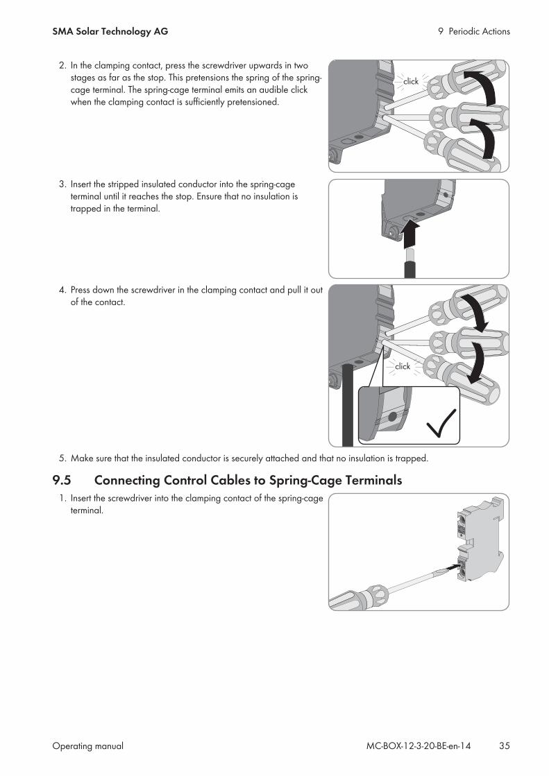
2. In the clamping contact, press the screwdriver upwards in twostages as far as the stop. This pretensions the spring of the spring-cage terminal. The spring-cage terminal emits an audible clickwhen the clamping contact is sufficiently pretensioned.
click
3. Insert the stripped insulated conductor into the spring-cageterminal until it reaches the stop. Ensure that no insulation istrapped in the terminal.
4. Press down the screwdriver in the clamping contact and pull it outof the contact.
click
5. Make sure that the insulated conductor is securely attached and that no insulation is trapped.
9.5 Connecting Control Cables to Spring-Cage Terminals1. Insert the screwdriver into the clamping contact of the spring-cage
terminal.
9 Periodic Actions SMA Solar Technology AG
Operating manualMC-BOX-12-3-20-BE-en-1436
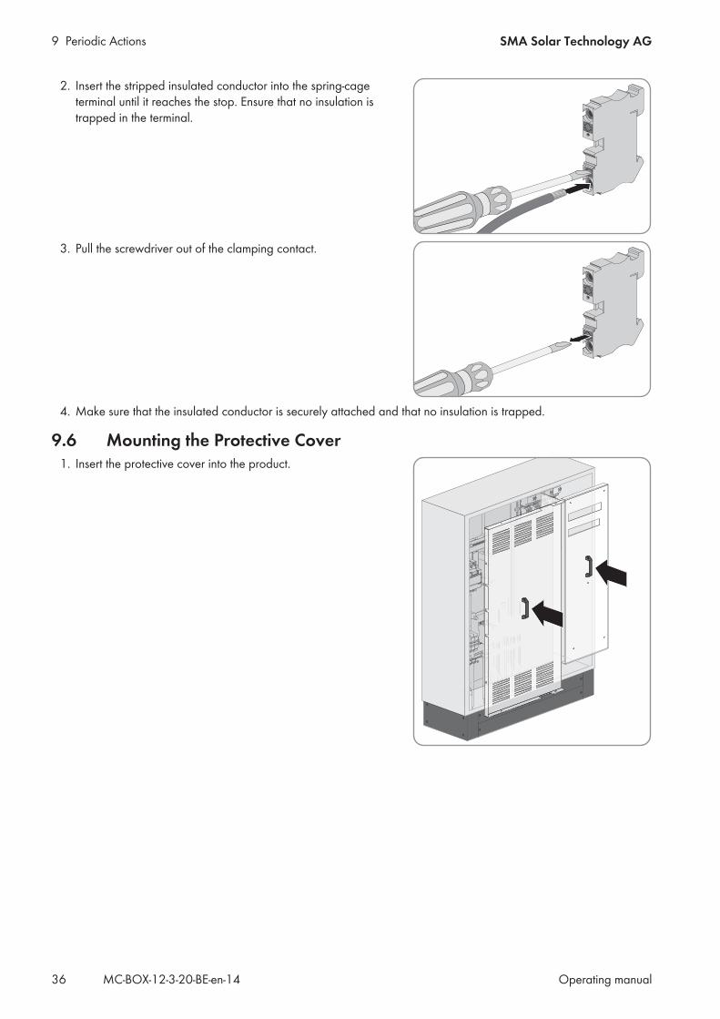
2. Insert the stripped insulated conductor into the spring-cageterminal until it reaches the stop. Ensure that no insulation istrapped in the terminal.
3. Pull the screwdriver out of the clamping contact.
4. Make sure that the insulated conductor is securely attached and that no insulation is trapped.
9.6 Mounting the Protective Cover1. Insert the protective cover into the product.

9 Periodic ActionsSMA Solar Technology AG
Operating manual 37MC-BOX-12-3-20-BE-en-14
2. Tighten all fastening screws (TX30, torque: 4 Nm).
10 Maintenance SMA Solar Technology AG
Operating manualMC-BOX-12-3-20-BE-en-1438
10 Maintenance10.1 Inspection of Residual-Current Devices
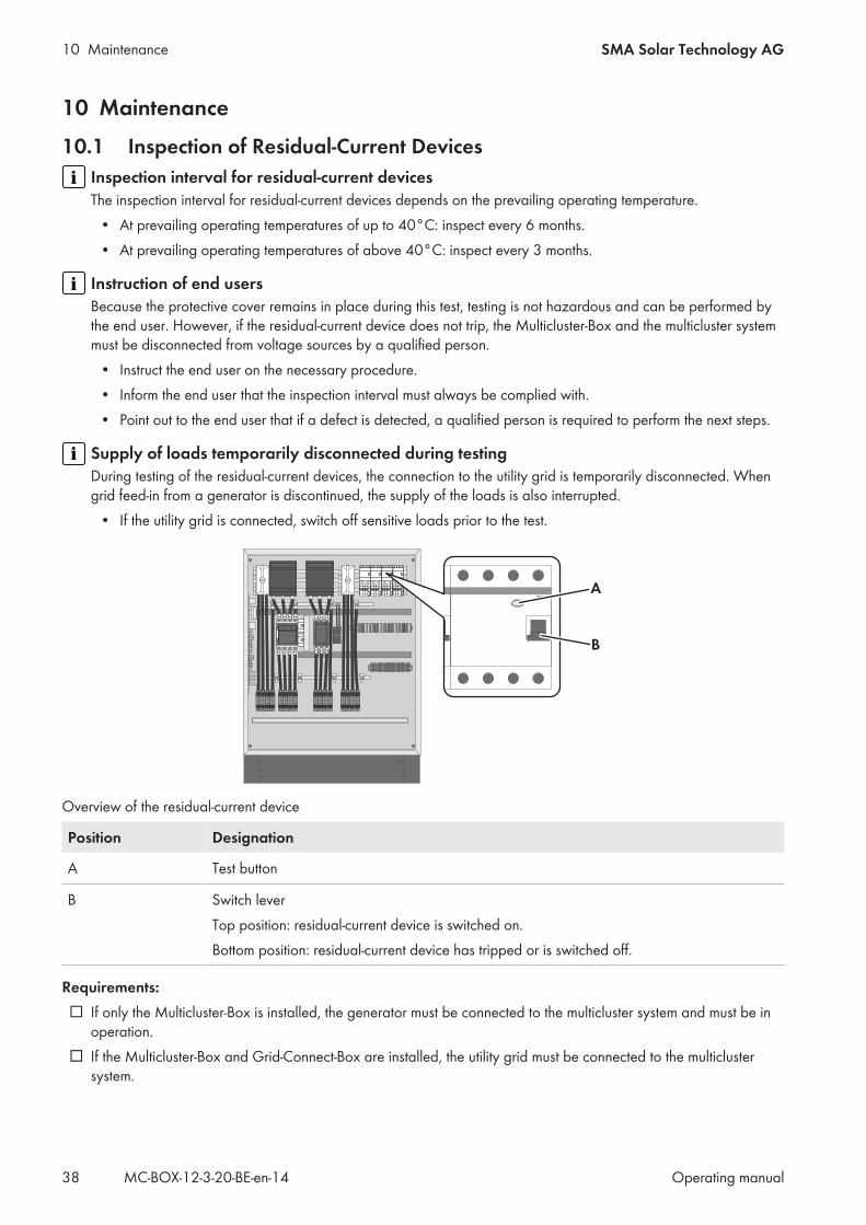
Inspection interval for residual-current devicesThe inspection interval for residual-current devices depends on the prevailing operating temperature.
• At prevailing operating temperatures of up to 40°C: inspect every 6 months.• At prevailing operating temperatures of above 40°C: inspect every 3 months.
Instruction of end usersBecause the protective cover remains in place during this test, testing is not hazardous and can be performed bythe end user. However, if the residual-current device does not trip, the Multicluster-Box and the multicluster systemmust be disconnected from voltage sources by a qualified person.
• Instruct the end user on the necessary procedure.• Inform the end user that the inspection interval must always be complied with.• Point out to the end user that if a defect is detected, a qualified person is required to perform the next steps.
Supply of loads temporarily disconnected during testingDuring testing of the residual-current devices, the connection to the utility grid is temporarily disconnected. Whengrid feed-in from a generator is discontinued, the supply of the loads is also interrupted.
• If the utility grid is connected, switch off sensitive loads prior to the test.
A
B
Overview of the residual-current device
Position Designation
A Test button
B Switch leverTop position: residual-current device is switched on.Bottom position: residual-current device has tripped or is switched off.
Requirements:☐ If only the Multicluster-Box is installed, the generator must be connected to the multicluster system and must be in
operation.☐ If the Multicluster-Box and Grid-Connect-Box are installed, the utility grid must be connected to the multicluster
system.

10 MaintenanceSMA Solar Technology AG
Operating manual 39MC-BOX-12-3-20-BE-en-14
Procedure:1. Stop the multicluster system at the master of the main cluster (see Sunny Island operating manual).2. On the residual-current device F141 press the [TEST] button.3. If the residual-current device does not trip after pressing the button, perform the following steps:
• Disconnect the Multicluster-Box and multicluster system from voltage sources (see Section 8, page 30)• Contact the Service (see Section 14, page 50). This will trigger the requisite spare parts order.
4. If the residual-current device has tripped, wait at least five seconds.5. Reactivate the residual-current device after at least five minutes. To do this, move the switch lever of the residual-
current device into the top position.6. In the Multicluster-Box, also check the residual-current devices F142, F143, F144 one after another. Use the
same procedure as described for the residual-current device F141.7. Start the multicluster system at the master of the main cluster (see Sunny Island operating manual).8. Document the test result in accordance with the locally applicable standards and directives. This is your proof that
regular inspection has taken place.
10.2 Checking the Surge ArrestersInspection interval for surge arrestersThe inspection interval for surge arresters depends on the prevailing operating temperature.
• At prevailing operating temperatures of up to 40°C: inspect every 6 months.• At prevailing operating temperatures of above 40°C: inspect every 3 months.
Instruction of end usersBecause the protective cover remains in place during this test, testing is not hazardous and can be performed bythe end user. However, if the residual-current device does not trip, the Multicluster-Box and the multicluster systemmust be disconnected from voltage sources by a qualified person.
• Instruct the end user on the necessary procedure.• Inform the end user that the inspection interval must always be complied with.• Point out to the end user that if a defect is detected, a qualified person is required to perform the next steps.
Procedure:1. Check whether the signal lights on the surge arresters F150 and F151 are showing green or red.
If the signal light on the surge arrester shows green, the surge arrester is in proper working order.If the signal light on the surge arrester shows red, the surge arrester is defective.
2. If the surge arrester is defective, contact Service (see Section 14, page 50). This will trigger the requisite spareparts order.
3. Document the test result in accordance with the locally applicable standards and directives. This is your proof thatregular inspection has taken place.
10 Maintenance SMA Solar Technology AG
Operating manualMC-BOX-12-3-20-BE-en-1440
10.3 General Maintenance WorkThe general maintenance work must be performed every twelve months.
DANGER
Danger to life due to electric shock when live components or cables are touchedHigh voltages are present in the conductive components or cables of the product. Touching live parts and cablesresults in death or lethal injuries due to electric shock.
• Do not touch non-insulated parts or cables.• Disconnect the product from voltage sources and make sure it cannot be reconnected before working on the
device.• Only disassemble the protective covers, if the product is disconnected from all voltage sources.• Wear suitable personal protective equipment for all work on the product.
NOTICE
Damage due to cleaning agentsThe use of cleaning agents may cause damage to the product and its components.
• Clean the product and all its components only with a cloth moistened with clear water.
Adverse ambient conditions reduce maintenance intervalsLocation and ambient conditions influence the maintenance intervals. Note that cleaning and corrosion protectionmay be required more frequently depending on the conditions at the installation site.
• If the product is subject to adverse ambient conditions, a reduction of the maintenance intervals isrecommended. Above all, the intervals between cleaning work and corrosion protection should be reduced.
• SMA recommends a monthly optical inspection to determine the maintenance requirement.
Required maintenance materials and toolsOnly those consumables and maintenance materials not normally included in the standard equipment of an electricallyqualified person are listed. It is taken for granted that standard tools and materials such as torque wrenches, one-contact voltage testers and wrenches will be available for all maintenance operations.☐ To repair minor surface corrosion damage: touch-up sticks, paint brushes, spray paint or, alternatively, 2K-PUR
acrylic paint (RAL-Farbe: 7035)☐ To repair large-surface corrosion damage: touch-up sticks or, alternatively, 2K-PUR acrylic paint (RAL color: 7035)☐ Abrasive cloth☐ Degreaser☐ For maintaining the seals: talcum, petroleum jelly or wax
Procedure:1. Check whether the inside of the product is soiled or moist.2. If the interior of the product is dirty, clean the product.3. If the interior of the product is moist or water has accumulated, dry the product out.4. Check whether all connections have been tightened with the correct torque (see Section 12, page 43)5. If any connections are not tightened with the correct torque, tighten with a suitable torque wrench.6. Check all power cables on the product for discoloration or changes in the appearance of the insulation.7. If any power cables are discolored or the appearance of the insulation has changed, replace these power cables.
10 MaintenanceSMA Solar Technology AG
Operating manual 41MC-BOX-12-3-20-BE-en-14
8. Check all insulated conductors, terminals and fuse elements in the product for discoloration or changes in theappearance of the insulation.
9. If any insulated conductors, terminals or fuse elements in the product are discolored or have changed inappearance, contact Service (see Section 14, page 50).
10. Check whether the product is free of corrosion damage.11. If the product displays minor corrosion damage, treat the affected area as follows:
• Sand the area.• Clean the area with degreaser.• Paint the area.
12. If the product displays large-scale corrosion damage, treat the entire surface as follows:• Sand the surface.• Clean the entire surface with degreaser.• Paint the entire surface.
13. Check whether all seals on the cabinet door are undamaged.14. If a seal is damaged, replace the seal.15. Apply talcum, petroleum jelly or wax to seals. This will prevent frost damage.

11 Decommissioning the Product SMA Solar Technology AG
Operating manualMC-BOX-12-3-20-BE-en-1442
11 Decommissioning the ProductDANGER
Danger to life due to electric shock when live components or cables are touchedHigh voltages are present in the conductive components or cables of the product. Touching live parts and cablesresults in death or lethal injuries due to electric shock.
• Do not touch non-insulated parts or cables.• Disconnect the product from voltage sources and make sure it cannot be reconnected before working on the
device.• Only disassemble the protective covers, if the product is disconnected from all voltage sources.• Wear suitable personal protective equipment for all work on the product.
Procedure:1. Make sure that the product and entire multicluster system have been disconnected from all voltage sources.2. Remove all fastening screws from the kick plates at the front and rear (TX 30). Retain the kick plates and the
fastening screws for later use.3. Disassemble the protective covers and base plates.4. Remove all cables from the product.5. Release and remove the fastening screws on the bottom of the product.6. Mount the protective covers and base plates.7. Close the cabinet doors.
8. WARNING
Danger of crushing if raised or suspended loads tip over or fallVibrations or careless or hasty lifting and transportation may cause the product to tip over or fall. This can resultin death or serious injury.
• Always transport the product as close to the floor as possible.• All means of transport and auxiliary equipment used must be designed for the weight of the product.
Weight: 228 kg.• Always transport and lift the product upright.• Always maintain a sufficient safety distance from the product during transport.• Take into account the center of gravity of the product. The center of gravity of the product is
approximately in the center of the cabinet and is marked on the packaging with the center of gravitysymbol.
9. Remount the kick plates on the product.10. Dispose of the product in accordance with the locally applicable disposal regulations for electronic waste.

12 Technical DataSMA Solar Technology AG
Operating manual 43MC-BOX-12-3-20-BE-en-14
12 Technical Data
Connection of loads
Number of terminals 1 x three-phase
Rated power 138 kW
Rated grid voltage between L and N 230 V
Rated grid voltage between L1 and L2 400 V
AC voltage range between L1 and N 172.5 V to 265 V
AC voltage range between L1 and L2 300 V to 433 V
Current at rated values 3 x 200 A
Terminals for connection N, L1, L2, L3 Spring-cage terminals
Maximum connectable conductor cross-section 150 mm²
Minimum connectable conductor cross-section 50 mm²
Fuse LV/HRC 1
Maximum permitted fuse rating for F102 200 A gG
Sunny Island Connection
Maximum number of Sunny Island inverters 12
Rated power of the Sunny Island inverters 72 kW
Rated operating voltage between L and N 230 W
Rated operating voltage between L1 and L2 400 W
Current at Sunny Island ratings 12 x 26 A
Unaffected short-circuit current / relative rated short-circuit current at the terminals ≤ 10 kA
Terminals for connection N, PE, L Spring-cage terminals
Maximum connectable conductor cross-section 10 mm²
Minimum connectable conductor cross-section 0.5 mm²
Fuses 12 x circuit breaker C40 A
Maximum permitted rated current of the back-up fuse 40 A gG
Short-circuit current breaking capacity of the back-up fuse ≥25 kA
Forward current of the back-up fuse ≤ 10 kA
Generator connection
Number of terminals 1 x three-phase
Rated operating voltage between L and N 230 V
12 Technical Data SMA Solar Technology AG
Operating manualMC-BOX-12-3-20-BE-en-1444
Rated operating voltage between L1 and L2 400 V
Rated grid input power 138 kW
AC input current 3 x 200 A
Terminals for connection N, PE, L1, L2, L3 Spring-cage terminals
Maximum connectable conductor cross-section 150 mm²
Minimum connectable conductor cross-section 50 mm²
Unaffected short-circuit current / relative rated short-circuit current at the terminals ≤ 10 kA
Fuse LV/HRC 1
Maximum permitted fuse rating for F101 200 A gG
Maximum permitted rated current of the back-up fuse 200 A gG
Short-circuit current breaking capacity of the back-up fuse ≥25 kA
Forward current of the back-up fuse ≤ 10 kA
Connection of PV system
Number of terminals 1 x three-phase
Rated power 138 kW
Rated operating voltage between L and N 230 V
Rated operating voltage between L1 and L2 400 V
Rated current / AC input current 3 x 200 A
Terminals for connection N, PE, L1, L2, L3 Spring-cage terminals
Maximum connectable conductor cross-section 150 mm²
Minimum connectable conductor cross-section 50 mm²
Unaffected short-circuit current / relative rated short-circuit current at the terminals ≤ 10 kA
Maximum permitted rated current of the back-up fuse 200 A gG
Short-circuit current breaking capacity of the back-up fuse ≥25 kA
Forward current of the back-up fuse ≤ 10 kA
Connection of NA-Box / Grid-Connect-Box
Number of terminals 1 x three-phase
Rated power 138 kW
Rated operating voltage between L and N 230 V
Rated operating voltage between L1 and L2 400 V
Rated current / AC input current 3 x 200 A
Terminals for connection N, PE, L1, L2, L3 Spring-cage terminals

12 Technical DataSMA Solar Technology AG
Operating manual 45MC-BOX-12-3-20-BE-en-14
Maximum connectable conductor cross-section 150 mm²
Minimum connectable conductor cross-section 50 mm²
Unaffected short-circuit current / relative rated short-circuit current at the terminals ≤ 10 kA
Maximum permitted rated current of the back-up fuse 200 A gG
Short-circuit current breaking capacity of the back-up fuse ≥25 kA
Forward current of the back-up fuse ≤ 10 kA
Connection of grounding
Width across flats for hexagon screws on the grounding busbar AF 17
Maximum torque 15 Nm
Maximum connectable conductor cross-section 120 mm²
Minimum connectable conductor cross-section 16 mm²
Data cable
Maximum overall length of the communication bus 30 m
Auxiliary electric circuits
Fuse 10x38 cylinder fuse
Maximum permitted fuse rating for F105, F106 and F110 1 A gG
Maximum permitted fuse rating for F111 6 A gG
Terminals for connecting the control cables Spring-cage terminals
Minimum connectable conductor cross-section 0.75 mm²
Maximum conductor cross-section 2.5 mm²
Unaffected short-circuit current / relative rated short-circuit current at the terminals ≤ 10 kA
Rated operating voltage of the AC auxiliary circuits 230 V
AC auxiliary circuit via X106:1 to X106:3: maximum permitted rated current ofthe back-up fuse
6 A gG
AC auxiliary circuit via X106:1 to X106:3: forward current of the back-up fuse ≤ 10 kA
Rated operating voltage of the DC auxiliary circuits 48 V
DC auxiliary circuit via X107:1 and X107:2: maximum permitted rated currentof the back-up fuse
6 A gG
DC auxiliary circuit via X107:1 and X107:2: forward current of the back-upfuse
≤ 10 kA
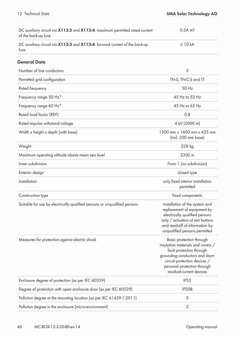
12 Technical Data SMA Solar Technology AG
Operating manualMC-BOX-12-3-20-BE-en-1446
DC auxiliary circuit via X113:3 and X113:4: maximum permitted rated currentof the back-up fuse
0.5A mT
DC auxiliary circuit via X113:3 and X113:4: forward current of the back-upfuse
≤ 10 kA
General Data
Number of line conductors 3
Permitted grid configuration TN-S, TN-C-S and TT
Rated frequency 50 Hz
Frequency range 50 Hz* 45 Hz to 52 Hz
Frequency range 60 Hz* 45 Hz to 65 Hz
Rated load factor (RDF) 0.8
Rated impulse withstand voltage 4 kV (2000 m)
Width x height x depth (with base) 1200 mm x 1600 mm x 435 mm(incl. 200 mm base)
Weight 228 kg
Maximum operating altitude above mean sea level 2300 m
Inner subdivision Form 1 (no subdivision)
Exterior design closed type
Installation only fixed interior installationpermitted
Construction type fixed components
Suitable for use by electrically qualified persons or unqualified persons Installation of the system andreplacement of equipment byelectrically qualified persons
only / actuation of test buttonsand read-off of information byunqualified persons permitted
Measures for protection against electric shock Basic protection throughinsulation materials and covers /
fault protection throughgrounding conductors and short-
circuit protection devices /personal protection through
residual-current devices
Enclosure degree of protection (as per IEC 60529) IP55
Degree of protection with open enclosure door (as per IEC 60529) IP20B
Pollution degree at the mounting location (as per IEC 61439-1:2011) 3
Pollution degree in the enclosure (micro-environment) 2

12 Technical DataSMA Solar Technology AG
Operating manual 47MC-BOX-12-3-20-BE-en-14
Protection class (as per IEC 417) 1
Overvoltage category (as per IEC 60664) Overvoltage category 3
EMC environment, emission (as per IEC 61439-1:2011) Electromagnetic interference,environment B (EMC directive,
Article 5 – Annex I.1.b)
EMC environment, interference immunity (as per IEC 61439-1:2011) Interference immunity,environment A (EMC Directive
Article 5 – Annex I.1.b)
EU Declaration of Conformity Yes
Operating temperature range** -25°C to +60°C
Humidity (non-condensing) 0% to 100%
* Depending on order option** At operating temperatures above 40°C, the Sunny Island inverters reduce their output power (derating).
Derating
138
035 604530 4025 50 55
MC-Box-12.3-20
Ambient temperature T [°C]
Out
put
pow
er /
Ra
ted
pow
er
Figure 13: Power-temperature curve
Output power / rated power up to 25°C 138 kW
Output power / rated power up to 60°C 1 derating according to power-temperature curve
Rated voltage / rated insulation voltage
Switch cabinet wiring L to N 250 V AC
Switch cabinet wiring L1 to L2 433 V AC
Auxiliary AC circuits 250 V AC
Auxiliary DC circuits 70 V DC

13 Multicluster Technology Terms SMA Solar Technology AG
Operating manualMC-BOX-12-3-20-BE-en-1448
13 Multicluster Technology Terms
Stand-alone gridA stand-alone grid is a utility grid which is independent of the public energy supply. A stand-alone grid with SunnyIsland is designed as a single-phase or three-phase AC grid which integrates various kinds of power generators (e.g.,PV systems, small wind turbine systems and diesel generators).Batteries for energy storage are also an integral part of stand-alone grids. The Sunny Island battery inverter forms astand-alone grid and maintains a stable energy supply by regulating all processes.
ClusterA cluster is made up of three Sunny Island inverters and one battery. One Sunny Island inverter per line conductor, i.e.,three Sunny Island inverters in total, are connected to form a three-phase stand-alone grid. Within the cluster, oneSunny Island is the master, while the other two are slaves.
Multicluster systemA multicluster system is made up of several clusters connected in parallel. The power of the multicluster systemincreases with the number of clusters. The individual clusters must be connected to a Multicluster-Box. The size of theMulticluster-Box is determined when the system is designed depending on the power requirement.
Multicluster-BoxThe Multicluster-Box is the AC main distributor in a multicluster system. The Multicluster-Box connects the Sunny Islandclusters with the loads and the power generators within a stand-alone grid.
MasterThe master is the control and communication center in a cluster. It carries out the following tasks:
• Switching slaves on and off• Controlling and monitoring the slaves, e.g., regulating frequency and voltage• Controlling battery charge and discharge• Monitoring battery capacity and state of charge• Storing cluster and battery data on SD memory card• Requesting diesel generator• Exchanging data with the masters of other clusters• Updating both slaves after firmware updates• Displaying system values and system states• Central capture of user entries
SlaveA slave is a functional unit subordinated to the master. A slave receives its configuration settings, current firmwareupdates, and start/stop commands from the master. It transmits its operating data to the master and executescommands issued by the master.
Main clusterThe main cluster is the leading cluster in the multicluster system. The master of the main cluster is the central userinterface for the main cluster and all extension clusters of a stand-alone grid. The master of the main cluster is superiorto the masters of the extension clusters. The tasks performed by the master of the main cluster include the following:
• Starting and stopping the multicluster system• Controlling and monitoring the masters of the extension cluster

13 Multicluster Technology TermsSMA Solar Technology AG
Operating manual 49MC-BOX-12-3-20-BE-en-14
• Communicating with the Multicluster-BoxIf the master of the main cluster stops operation, the entire multicluster system shuts down. If a diesel generator isintegrated in the stand-alone grid, it will take over the power supply to the loads in this case.
Extension clusterEach extension cluster is subordinate to the main cluster.The master of the extension cluster follows the instructions issued by the master of the main cluster, and sends theoperating data of its cluster to the master of the main cluster. If the master of an extension cluster stops operation, thenonly this cluster shuts down. In this case, the multicluster system continues to operate with reduced power.

14 Contact SMA Solar Technology AG
Operating manualMC-BOX-12-3-20-BE-en-1450
14 ContactIf you have technical problems with our products, please contact the SMA Service Line. The following data is requiredin order to provide you with the necessary assistance:
• Box:– Device type– Serial number
• Battery inverter:– Device type– Quantity
• PV inverter:– Device type– Quantity
• Electrical loads:– Device type– Quantity
• Type, power and maximum current for the generator (if present)• Grid-Connect-Box (if available)
– Device type– Serial number
• Batteries:– Type– Nominal capacity and nominal voltage (with lead-acid batteries)
DeutschlandÖsterreichSchweiz
SMA Solar Technology AGNiestetalSunny Boy, Sunny Mini Central,Sunny Tripower, Sunny Highpower:+49 561 9522‑1499Monitoring Systems(Kommunikationsprodukte):+49 561 9522‑2499Hybrid Controller:+49 561 9522-3199Sunny Island, Sunny Boy Storage,Sunny Backup:+49 561 9522-399Sunny Central, Sunny Central Storage: +49 561 9522-299SMA Online Service Center:www.SMA-Service.com
BelgienBelgiqueBelgiëLuxemburgLuxembourgNederland
SMA Benelux BVBA/SPRLMechelen+32 15 286 730for Netherlands: +31 30 2492 000SMA Online Service Center:www.SMA-Service.com
ČeskoMagyarországSlovensko
SMA Service Partner TERMS a.s.+420 387 6 85 111SMA Online Service Center:www.SMA-Service.com
Türkiye SMA Service Partner DEKOMTelekomünikasyon A. Ş.+90 24 22430605SMA Online Service Center:www.SMA-Service.com

14 ContactSMA Solar Technology AG
Operating manual 51MC-BOX-12-3-20-BE-en-14
France SMA France S.A.S.Lyon+33 472 22 97 00SMA Online Service Center :www.SMA-Service.com
ΕλλάδαΚύπρος
SMA Service Partner AKTOR FM.Αθήνα+30 210 8184550SMA Online Service Center:www.SMA-Service.com
EspañaPortugal
SMA Ibérica Tecnología Solar, S.L.U.Barcelona+34 935 63 50 99SMA Online Service Center:www.SMA-Service.com
United Kingdom SMA Solar UK Ltd.Milton Keynes+44 1908 304899SMA Online Service Center:www.SMA-Service.com
Italia SMA Italia S.r.l.Milano+39 02 8934-7299SMA Online Service Center:www.SMA-Service.com
Australia SMA Australia Pty Ltd.SydneyToll free for Australia:1800 SMA AUS(1800 762 287)International: +61 2 9491 4200
United ArabEmirates
SMA Middle East LLCAbu Dhabi+971 2234 6177SMA Online Service Center:www.SMA-Service.com
India SMA Solar India Pvt. Ltd.Mumbai+91 22 61713888
ไทย SMA Solar (Thailand) Co., Ltd.กรุงเทพฯ+66 2 670 6999
대한민국 SMA Technology Korea Co., Ltd.서울+82-2-520-2666
South Africa SMA Solar Technology South AfricaPty Ltd.Cape Town08600SUNNY (08600 78669)International: +27 (0)21 826 0699SMA Online Service Center:www.SMA-Service.com
ArgentinaBrasilChilePerú
SMA South America SPASantiago de Chile+562 2820 2101
Other coun-tries
International SMA Service LineNiestetal00800 SMA SERVICE(+800 762 7378423)SMA Online Service Center:www.SMA-Service.com

www.SMA-Solar.com