operating manual - mutec · the operating manual for further information. this concludes the...
TRANSCRIPT
Operating Manual
MUTEC GmbH · Fon 0049- (0)30-74 68 80-0 · contact@mutec-net .com · www.mutec-net .com
facebook.com/mutecpro pinterest .com/mutecpro https : / /p lus.google.com/116705378800155548696


3
Content
Safety Instructions .............................................................................................................................................................. 4
Warranty Regulations ........................................................................................................................................................ 5
IntroductionQuick Start Guide .......................................................................................................................................................................... 6
General Description & Features ..................................................................................................................................................... 8
Applications & Peripheral MUTEC Products .................................................................................................................................. 8
Product Registration for Warranty and Support & Social Media ................................................................................................... 9
InstallationContent of the Box ........................................................................................................................................................................ 9
Placing the Device ......................................................................................................................................................................... 9
Wiring the Interfaces & General Recommendations for Interface Wirings & Cables ................................................................... 11
Control Elements and TerminalsFront Panel .................................................................................................................................................................................. 12
Rear Panel ................................................................................................................................................................................... 13
USB Driver Installation & Windows SettingsMUTEC USB Audio Class 2.0 Driver for Windows ........................................................................................................................ 15
Driver Download and Installation Procedure ............................................................................................................................... 16
Windows Settings ....................................................................................................................................................................... 17
Operation General System Operation .......................................................................................................................................................... 19
Operation of the MC-3+ Smart Clock USB .................................................................................................................................. 20
Status Information & Generic Functions...................................................................................................................................... 24
AppendixPin Assignment of the Connectors & Switching off the Termination of the Word Clock- & 1-10M Clock Input ........................... 26
Technical Data ............................................................................................................................................................................. 28
Generatable Word Clock (WCLK) Frequencies & Generatable AES11 & S/P-DIF blank frame Frequencies ................................... 29

4
Safety Instructions
General Instructions To reduce the risk of fire or electrical shock, do not expose this appliance to rain or moisture, direct sunlight or excessive heat from sources such as radiators or spotlights. No user service-able parts are inside. Repair and maintenance must be carried out by qualified personnel au-thorized by MUTEC GmbH! The unit has been designed for operation in a standard domestic environment. Do NOT expose the unit and its accessories to rain, moisture, direct sunlight or excessive heat produced by such heat sources as radiators or spotlights! The free flow of air inside and around the unit must always be ensured.
Initial OperationPrior to the initial operation of the unit, the appliance, its accessories and packaging must be inspected for any signs of physical damage that may have occurred during transit. If the unit has been damaged mechanically or if liquids have been spilled inside the enclosure, the appliance may not be connected to the mains or must be disconnected from the mains im-mediately! If the unit is damaged, please do NOT return it to MUTEC GmbH, but notify your dealer and the shipping company immediately, otherwise claims for damage or replacement may not be granted.
If the device is left in a low-temperature environment for a long time and then is moved to a room-temperature environment, condensation may occur on the inside and the exterior. To avoid short-circuits and flashovers, be sure to wait one or two hours before putting the device into operation.
Power SupplyThe device contains a self-adapting wide-range power supply supporting the majority of global standard line voltages within a range of 90…250 V, with no need for making adjustments. Make sure that your line-voltage source provides a supply voltage within the specified range. In addition, make sure that the device is properly grounded via the local electric installation.
Please use the enclosed power cord (see packaging) to connect the unit to the mains. Switch the unit off before you attempt to connect it to the mains. Connect the power cord to the unit, then to a standard 3-pin mains outlet. To draw the power cord, never pull on the cable but on the mains plug!
The unit must be grounded during operation!
For information on the power-inlet wiring, refer to the »Wiring of connectors« section in the appendix. Disconnect the device from the mains when not using it for an extended period!
TrademarksMUTEC GmbH assumes no liability for any incorrect information given in this manual. Please note that all software/hardware product names are registered trademarks of their respective owners. No part of this manual may be reproduced, copied or converted to a machine-reada-ble form or electronical media without a written permission of MUTEC GmbH. We reserve the right to change or improve our products without notice. © MUTEC GmbH 2013
This symbol, a flash of lightning inside a triangle, alerts you to the presence of uninsulated dangerous voltage inside the enclosure - voltage that may be
sufficient to constitute a risk of shock.
This symbol, an exclamation mark inside a triangle, alerts you to important operating or safety instruc-tions in this manual.
Declaration of Conformity We herewith confirm that the product complies with the European Commission’s standards on electromagnetic compatibility.
Interference emission: EN 50081-1, 1992 Resistance to interference: EN 50082-1, 1992
Presupposed as operation condition is that all clock outputs are connected with high-quality and good shielded BNC 75 ohms cable.
!
R I S K O FELECTRICAL SHOCK!
C A U T I O N
!

5
Warranty Regulations
§1 WarrantyMUTEC GmbH warrants the flawless performance of this product to the original buyer for a period of two (2) years from the date of purchase. If any failure occurs within the specified warranty period that is caused by defects in material and/or workmanship, MUTEC GmbH shall either repair or replace the product free of charge within 90 days. The purchaser is not entitled to claim an inspection of the device free of charge during the warranty period. If the warranty claim proves to be justified, the product will be returned freight prepaid by MUTEC GmbH within Germany. Outside Germany, the product will be returned with the additional international freight charges payable by the customer. Warranty claims other than those indicated above are expressly excluded.
§2 Warranty TransferabilityThis warranty is extended exclusively to the original buyer who bought the product from a MUTEC GmbH specialized dealer or distributor, and is not transfer-able to anyone who may subsequently purchase this product. No other person (retail dealer, distributor, etc.) shall be entitled to give any warranty promise on behalf of MUTEC GmbH.
§3 Waranty RegulationsThe return of the completed registration card, or online registration on one of the websites specified below, is a condition of warranty. Failing to register the device before returning it for repair will void the extended warranty.
The serial number on the returned device must match the one stated on the registration card or entered during online registration. Otherwise, the device will be returned to the sender at the sender’s expense. Any returned device must be accompanied by a detailed error description and a copy of the original sales receipt issued by a MUTEC dealer or distributor. The device must be returned free of shipping expenses and in the original package, if possible; otherwise, the sender has to provide comparably protective packaging. The sender is fully responsible for any damage or loss of the product when shipping it to MUTEC GmbH.
§4 Limitation of WarrantyDamages caused by the following conditions are not covered by this warranty:
Damages caused by every kind of normal wear and tear (e.g. displays, LEDs, potentiometers, faders, switches, buttons, connecting elements, printed labels, cover glasses, cover prints, and similar parts). Functional failure of the product caused by improper installation (please observe CMOS components handling instructions!), neglect or misuse of the product, e.g. failure to operate the unit in compliance with the instructions given in the user or service manuals. Damage caused by any form of external mechanical impact or modification. Damage caused by the user’s failure to connect and operate the unit in compliance with local safety regulations. Damage caused by force majeure (fire, explosion, flood, lightning, war, vandalism, etc.). Consequential damages or defects in products from other manufacturers as well as any costs resulting from a loss of production.
Repairs carried out by personnel which is not authorized from MUTEC GmH
§5 Repairs To obtain warranty service, the buyer must call or write to MUTEC GmbH before returning the unit. All inquiries must be accompanied by a description of the problem and the original buyer’s invoice. Devices shipped to MUTEC GmbH for repair without prior notice will be returned to the sender at the sender’s expense. In case of a functional failure please contact:
MUTEC Gesellschaft fuer Systementwicklung und Komponentenvertrieb mbH Siekeweg 6/8 • 12309 Berlin • Germany • Fon 030-746880-0 • Fax 030-746880-99 • [email protected] • www.mutec-net.com

XX XX
6
Quick Start Guide
Thank you very much for buying the MC-3+ Smart Clock USB, an Audio Re-Clocker, USB Interface and Synchronizable Digital Audio Master Clock Generator, and welcome to the MUTEC user community! We hope that you will have a wonderful listening experience with this product.
Quick Start Guide for Computer AudioWhile your MC-3+USB can be used in a variety of applications as described in the operating manual, this quick start guide is intended to get you off the ground for computer or music server audio playback via USB as quickly as possible.
Windows Driver InstallationIn order to operate the MC-3+USB with a Windows computer it is required to install MUTEC’s USB Audio Class 2.0 Driver for Windows available on our website. The driver provides an ASIO-2.2 compliant software interface and interacts with Windows as a standard WDM/DirectX compatible sound device. Optimized for low latency and low CPU load, the driver implements a transparent, bit-perfect playback data path.
Please do not operate the MC-3+USB during driver installation!
Download the driver at: http://www.mutec-net.com/product_mc-3-plus-usb.php?lng=en#download
After successful download double click on the ZIP file for unpacking and follow the instructions during the installation procedure.
Detailed information can be found on page 16 of this operating manual.
ConnectionsConnect your Windows PC / MAC with the MC-3+USB using the supplied USB cable or an alternative USB cable of your choosing.
Connect the MC-3+USB to your DAC using any of the available digital audio outputs like AES3, S/P-DIF coaxial, optical, BNC, or AES3id via BNC.
Establish a power connection with the supplied power cord.

XX XX
7
Quick Start Guide
Hardware SetupPower up the MC-3+USB via the switch on the rear of the device.
The MC-3+USB has several modes of operation, but for audio re-clocking you need to set it to »INTERN« & »RE-CLK«.
Press the MENU button once (LEDs flash) and use the SELECT button to cycle through the MODE menu until the top (IN-TERN) and bottom (RE-CLK) LEDs in the MODE column both light up.
As a result the top three LEDs in the REFERENCE menu should light up at once as the default setting and indicate that the USB input has been selected as audio input. When sending a valid audio stream into the USB input, the top blue LOCK LED and the red AUDIO LED in the STATUS column should now be illuminated confirming a lock to the USB audio stream as reference (see sketch below, e.g. sampling rate of audio input reference = 192.0 kHz).
When you want to use one of the other inputs as audio source, press the menu button to switch to the REFERENCE menu (LEDs flash) and use the SELECT button to cycle through the REFERENCE menu until you have activated the desired input.
Windows Software SetupAs a last step you need to set up the MC-3+USB as a standard sound device. Click the »Start Menu« button and select »Control Panel«. Click on »Sound« in the »Hardware & Sound« area to select the MC-3+USB as a playback device. Refer to page 16 in the operating manual for further information.
This concludes the initial setup for computer audio playback on a Windows PC. Please refer to the operating manual for addi-tional information and if you should have any questions.
MAC Software SetupThe MC-3+ Smart Clock USB acts as a class-compliant Core Audio device on MAC computers. Therefore, there is no need for any driver installation. When the MC-3+USB is powered up and a USB connection has been established, your MAC will automatically detect the new audio device and select it as the current playback device.
If not, check the »Sound« menu in your OSX system preferences and select »MC-3+ Smart Clock USB 2.0« as the output device.
This concludes the initial setup for computer audio playback on a MAC. Please refer to the user manual for additional informa-tion and if you should have any questions.
CLOCK MULTIPLIERS
1 2 3 4
MODE
32.0
48.0
INTERN
RE-CLK
EXTERN
×1
×8
×4
×244.1
88.2
96.0 ×256 SC
×512
×256 WC176.4
192.0
REFERENCE CLOCK OUT
WCLK
1–10.0MUSB-PCM
AES3/11S/P-DIF BNC AES3/11id
S/P-DIF OP USB-DSD/DoP
STATUS
LOCK MAIN REF
LOCK RE-CLK REF
CLOCK IN
32.0
48.0
DoP
AUDIO
HOLD
44.1
DSD
88.2
64
128
96.0
176.4
192.0256
1–10.0M
8
Introduction
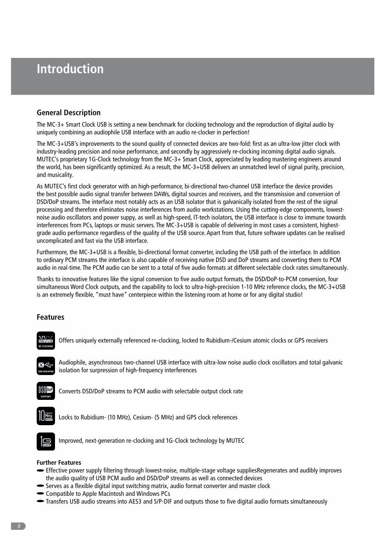
General DescriptionThe MC-3+ Smart Clock USB is setting a new benchmark for clocking technology and the reproduction of digital audio by uniquely combining an audiophile USB interface with an audio re-clocker in perfection!
The MC-3+USB’s improvements to the sound quality of connected devices are two-fold: first as an ultra-low jitter clock with industry-leading precision and noise performance, and secondly by aggressively re-clocking incoming digital audio signals. MUTEC’s proprietary 1G-Clock technology from the MC-3+ Smart Clock, appreciated by leading mastering engineers around the world, has been significantly optimized. As a result, the MC-3+USB delivers an unmatched level of signal purity, precision, and musicality.
As MUTEC’s first clock generator with an high-performance, bi-directional two-channel USB interface the device provides the best possible audio signal transfer between DAWs, digital sources and receivers, and the transmission and conversion of DSD/DoP streams. The interface most notably acts as an USB isolator that is galvanically isolated from the rest of the signal processing and therefore eliminates noise interferences from audio workstations. Using the cutting-edge components, lowest-noise audio oscillators and power suppy, as well as high-speed, IT-tech isolators, the USB interface is close to immune towards interferences from PCs, laptops or music servers. The MC-3+USB is capable of delivering in most cases a consistent, highest-grade audio performance regardless of the quality of the USB source. Apart from that, future software updates can be realised uncomplicated and fast via the USB interface.
Furthermore, the MC-3+USB is a flexible, bi-directional format converter, including the USB path of the interface. In addition to ordinary PCM streams the interface is also capable of receiving native DSD and DoP streams and converting them to PCM audio in real-time. The PCM audio can be sent to a total of five audio formats at different selectable clock rates simultaneously.
Thanks to innovative features like the signal conversion to five audio output formats, the DSD/DoP-to-PCM conversion, four simultaneous Word Clock outputs, and the capability to lock to ultra-high-precision 1-10 MHz reference clocks, the MC-3+USB is an extremely flexible, “must have” centerpiece within the listening room at home or for any digital studio!
Features
Offers uniquely externally referenced re-clocking, locked to Rubidium-/Cesium atomic clocks or GPS receivers
Audiophile, asynchronous two-channel USB interface with ultra-low noise audio clock oscillators and total galvanic isolation for surpression of high-frequency interferences
Converts DSD/DoP streams to PCM audio with selectable output clock rate
Locks to Rubidium- (10 MHz), Cesium- (5 MHz) and GPS clock references Improved, next-generation re-clocking and 1G-Clock technology by MUTEC
Further FeaturesEffective power supply filtering through lowest-noise, multiple-stage voltage suppliesRegenerates and audibly improves the audio quality of USB PCM audio and DSD/DoP streams as well as connected devices Serves as a flexible digital input switching matrix, audio format converter and master clock Compatible to Apple Macintosh and Windows PCs Transfers USB audio streams into AES3 and S/P-DIF and outputs those to five digital audio formats simultaneously

9
Introduction
Converts between USB PCM audio, USB DSD/DoP audio, AES3 and S/P-DIF, as well as between AES11 and Word Clock Highly compatible USB audio class 2.0 driver for Windows supporting ASIO, MME, DirectSound, WASAPI, Kernel Streaming, PCM 16Bit, 24Bit, 32Bit and Float-32Bit at all clock rates between 44.1kHz and 192.0kHz Ultra-low jitter Word Clock generation with clock rates up to 1.536 kHz Scalable to FS1x512 clock rates, 22.5792 MHz & 24.576 MHz, for e.g. high-end audio interfaces Digitally-compensated clock accuracy für highest precision of the generated clock signals Generates Word Clocks, Super Clocks, AES3 + S/P-DIF blanks simultaneously Uninterruptable, fail-safe clock generation in all operation modes Eliminates so-called digital “clicks and pops” Individual lock indicators for the clock or audio reference and the re-clock reference USB, AES/EBU, AES/EBUid and S/P-DIF interfaces in one box S/P-DIF interconnections via BNC, RCA and optical interfaces available as in- and outputs Front panel lock-out for preventing of misuse Rack-space-saving 9.5“ housing Built-in, universal power supply
ApplicationsOptimizes jitter-affected digital sources like CD transports, satellite ratios, and streamers Ideally suited as a signal conditioner to audibly improve any D/A converter Enables computer audio via USB at highest fidelity quality Serves as a digital audio switching matrix, format converter, and master clock Exports and converts native DSD signals from the computer Isolates USB audio streams to digital devices Improves jitter-affected digital sources for archival and audio processing purposes
Peripheral MUTEC ProductsSignal Distribution Amplifiers
MC-2 The MC-2 is a high-performance digital audio and reference sync signal distribution amplifier for AES3/11 and AES3/11id signals. The unit distributes and converts between the mentioned AES signals and interface standards.MC-7 The MC-7 is a flexible, high-performance 8-channel Word Clock distribution amplifier and audio clock converter.
Format and Sampling Rate ConvertersMC-4 The MC-4 is a high-performance digital audio multichannel format and sampling rate converter for ADATTM, AES3 and S/P-DIF.MC-6 The MC-6 is a high-performance digital audio dual channel format converter for AES3, AES3id and S/P-DIF. MC-8 + MC-8.1 The MC-8 and MC-8.1 are 8 channel, high-performance digital audio and sampling rate converters for AES3 and AES3id.
AccessoriesOptical cables in different lenghts from 0.5 m to 20 m for S/P-DIF and ADATTM transfers. MW-02/19, Mounting plate to install two MC products side by side into one unit of a 19” rack. MW-03/19, Set of two rack mounting angles to install one MC product on the rear side of a 19” rack. MW-05/19, Set of two rack mounting angles to install one MC product frontally into one unit of a 19” rack.
For all peripheral products please have a look on our website: www.mutec-net.com

10
Installation
Product Registration for Warranty and SupportWe ask you to be so kind to register your MUTEC product through our website immediately after buying. This ensures full warranty services over a period of two years after purchasing the product. More-over, for all registered products we offer to our customers technical support. We also will inform you about product updates and new products which may of interest for you (on voluntary base, of course).
Please regsiter your product at:
www.mutec-net.com > Service > Product Registration
Or for direct access type in the following URL into your browser:
http://www.mutec-net.com/produktregistrierung.php?lng=en
Social Media
Content of the BoxYour MC-3+ Smart Clock USB was packed carefully. Nevertheless we recommend to check the content directly after opening the package:
1 x MC-3+ Smart Clock USB 1 x USB cable 1 x RCA-BNC adapter 1 x Power cable 1 x Manual
If there are any damages visible, please refer to Safety Instructions and Warranty Regulations for further details.
Placing the DeviceThe unit should be set up as closely as possible to the devices to which it will be connected with to avoid excessive cable lengths. The four custom-designed case feets include a rubber ring to protect the ground’s surface from being damaged.
The device can be mounted into a standard 19“ rack and will require 1U. Therefore, we offer an optional rack mounting kit, called MW-05/19. This includes two rack angles which need to be screwed at each side of the device‘s case. Before mounting the device into a 19“ rack, please unscrew the four rubber feet with a suitable screwdriver. Install the device so that 1U of rack space is left free both above and below the device to allow for sufficient ventilation! Additional slide-in rails on the rack inside are recommended for safe installation. This will also avoid long-term mechanical deformation of the housing.
Attention Before installing the unit the section Safety Instructions located at the beginning of this manual should be read carefully!
Never expose the device and accessories to rain, moisture, direct sunlight, or excessive heat produced by radiators, heaters, or spot lights! Sufficient air circulation in the environment of the device must be ensured!
facebook.com/mutecpro pinterest .com/mutecpro
https : / /p lus.google.com/116705378800155548696

11
Installation
Wiring the InterfacesWord Clock To allow for the synchronization of signals, the interfaces of all devices involved must be properly connected to each other to ensure a logical signal flow. Always be sure to connect the Word Clock output(s) to the corresponding input(s) of the device(s) you wish to synchronize. Cable lengths should be kept as short as possible to minimize signal losses and/or interferences!
For the transmission of Word Clock signals, unsymmetrical cables with a impedance of 75 Ω and BNC connectors on both ends are used. Typically, such cables are marked with »RG-59U, RG59B/U«.
Additionally, make sure that the Word Clock input(s) incorporate a 75 Ω terminating resistor! Most Word Clock inputs allow for enabling/disabling the termination with a so-called »termination-switch«, which may be located on the outside or inside of the device. For devices which have no termination of the Word Clock input, e.g. RME Hammerfall with Word Clock i/o, Alesis BRC or M-Audio ProFire Light bridge, you can use an additional BNC-T piece to terminate the input. Plug the T piece with its center connector into the input of the receiving device. Then, connect the cable coming from the Word Clock output to one of the lateral connectors, and the other connector of the BNC-T piece to a 75 Ω resistor forming the BNC termination.
Basically, you should avoid »looping through« Word Clock leads by means of passive BNC-T pieces to preserve the signal qual-ity, as level drops will be the result. If there is no other way to wire your set-up, please make sure that all Word Clock inputs (except for the last device in the chain) have their terminations disabled! In a serial Word Clock chain only the last clock input should have a termination! Never connect more than three devices in series to one output!
AES/EBU Connect the AES/EBU interfaces with the help of balanced electrical cables equipped with XLR connectors on both ends. The speci-fications stipulate a specific cable impedance of 110 Ω (ask your retailer for a confirmation of this value when buying the cables).
S/P-DIF Two coaxial S/P-DIF interfaces are available, one based on standard RCA, the other one based on BNC connectors. Connect these interfaces with help of unbalanced electrical cables equipped with RCA respectively BNC connectors on both ends. The specifications stipulate a specific cable impedance of 75 Ω for both. Ask your retailer for a confirmation of this value when buying the cables.
Connect the optical S/P-DIF interface with the help of Toshiba TOSLINK™ compliant optical fiber cables. You can use both plastic and glass fiber-based cables.
General Recommendations for Interface Wirings & Cables
Word Clock If a cable with a different impedance than 75 Ω is used, a dramatic deterioration of the signal quality is the result! In this case, the sound quality and synchronization of all devices involved can be impaired.
It is imperative that the lengths of all cables connected are largely the same to ensure that all devices will be synchronized in phase (exception: cable tolerances).
We recommend using high-grade cables with a good shielding. A length of max. 10 meters (approx. 30 feets) should not be exceeded!
AES/EBU & S/P-DIF Interconnections When working with XLR-based AES3/-11 or RCA-based S/P-DIF audio signals at high sampling rates , well-shielded electrical cables are mandatory to avoid increased radiation! Standard cables are normally useable for sampling rates up to 50.0kHz.
When interconnecting the optical S/P-DIF interfaces with plastic fiber cables, lengths of 10 meters should not be exceeded, to ensure reliable transmission of your digital audio signals. Glass fiber cables may transfer data reliably even over greater distances while keeping the signal’s performance on a much higher level than plastic fibre cables can do during transmission!
12
Control Elements and Terminals
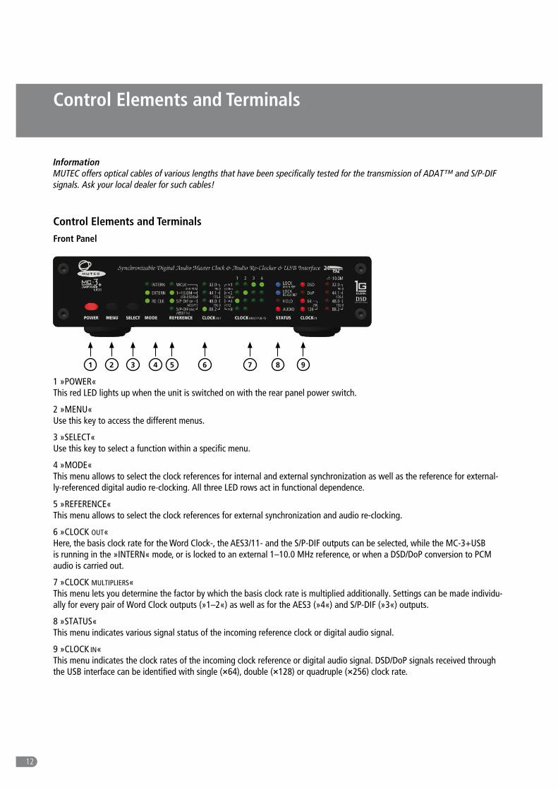
Control Elements and TerminalsFront Panel
432 51 6 7
1 »POWER« This red LED lights up when the unit is switched on with the rear panel power switch.
2 »MENU« Use this key to access the different menus.
3 »SELECT« Use this key to select a function within a specific menu.
4 »MODE« This menu allows to select the clock references for internal and external synchronization as well as the reference for external-ly-referenced digital audio re-clocking. All three LED rows act in functional dependence.
5 »REFERENCE« This menu allows to select the clock references for external synchronization and audio re-clocking.
6 »CLOCK OUT« Here, the basis clock rate for the Word Clock-, the AES3/11- and the S/P-DIF outputs can be selected, while the MC-3+USB is running in the »INTERN« mode, or is locked to an external 1–10.0 MHz reference, or when a DSD/DoP conversion to PCM audio is carried out.
7 »CLOCK MULTIPLIERS« This menu lets you determine the factor by which the basis clock rate is multiplied additionally. Settings can be made individu-ally for every pair of Word Clock outputs (»1–2«) as well as for the AES3 (»4«) and S/P-DIF (»3«) outputs.
8 »STATUS« This menu indicates various signal status of the incoming reference clock or digital audio signal.
9 »CLOCK IN« This menu indicates the clock rates of the incoming clock reference or digital audio signal. DSD/DoP signals received through the USB interface can be identified with single (×64), double (×128) or quadruple (×256) clock rate.
8 9
Information MUTEC offers optical cables of various lengths that have been specifically tested for the transmission of ADAT™ and S/P-DIF signals. Ask your local dealer for such cables!

13
Control Elements and Terminals
542 61 7 11
1 »WCLK OUT 1– 2« These 2 pairs of Word Clock outputs transfer all standard Word Clock rates, Word Clock × 256 for older digidesign ProTools™ systems and × 512 clock rates for special High-End interfaces. Their numbering is aligned to the apropriate menus on the front panel. The individual BNC connectors are pairwise marked as »A« and »B«, which allows for, e.g. simple documentation of the connected devices. The impedances of all connectors are 75 Ω (BNC connectors, female).
2 »S/P-DIF OUT 3« The S/P-DIF output transmits an unbalanced electrical S/P-DIF digital audio or blank frame signal in compliance with the IEC 60958 standard. The interface impedance is 75 Ω (BNC connectors, female).
3 »AES3/11id OUT 4« The AES/EBUid output transmits an unbalanced electrical digital audio or blank-frame signal in compliance with AES3id-2001 (revision of 1995) or AES11-2003 (revision of 1997).
4 »S/P-DIF OUT 3« These two S/P-DIF outputs, available as optical and coaxial interfaces, transmit an optical (»OP«) and unbalanced electrical (»CO«) S/P-DIF digital audio or blank frame signal in compliance with the IEC 60958 standard. The coaxial interface impedance is 75 Ω. (RCA connector), the optical interface offers a Toshiba ToslinkTM connector, EIAJ standard. Its numbering is aligned to the apropriate menu on the front panel.
5 »AES3/11 OUT 4« This AES/EBU output transmits a transformer-balanced electrical digital audio or blank-frame signal in compliance with AES3-1997 (revision of 1992) or AES11-2003 (revision of 1997). Its numbering is aligned to the apropriate menu on the front panel. The output impedance is 110 Ω (XLR connector, male).
6 »AES3/11 IN« This AES/EBU input receives a balanced electrical digital audio or blank-frame signal in compliance with AES3-1997 (revision of 1992) or AES11-2003 (revision of 1997). The input impedance is 110 Ω (XLR connector, female).
7 »S/P-DIF IN (OP)« This optical S/P-DIF input receives an optical S/P-DIF digital audio or blank frame signal in compliance with the IEC 60958 standard. The optical interface offers a Toshiba ToslinkTM connector, EIAJ standard.
8 »USB I/O« This USB (Universal Serial Bus) interface receives or sends data streams in compliance with USB2.0. When connecting the MC-3+USB to a MS Windows PC, please install the provided USB2.0 Audio Class Driver for Windows at first on your computer. Refer to the »Installation of the USB2.0 Audio Class Driver for Windows« section on page 13 for further details (USB-B connec-tor).
Rear Panel 83 10
9

14
Control Elements and Terminals
9 »S/P-DIF & AESid IN« This input receives either an unbalanced electrical digital audio or blank-frame signal in compliance with AES3id-2001 (revision of 1995) or AES11-2003 (revision of 1997), or an unbalanced electrical digital audio or blank-frame signal in compliance with the IEC 60958 standard. The input impedance is 75 Ω (BNC connector, female).
If you have for input of S/P-DIF signals only a cable with RCA, respectively Cinch connectors available, then use the RCA to BNC adpater included in delivery.
10 »WCLK & 1–10M IN« This input can receive a Word Clock, a Word Clock × 256 as well as a 1–10.0 MHz reference clock signal. The impedance of the connector is 75 Ω (BNC connector, female).
11 »MAINS IN«, Power Switch + Mains connector (IEC) This is the main switch for switching the device on and off. Connect the supplied IEC power cable to the device‘s mains con-nector. Make sure that the power switch is turned off before connecting the device to your power source finally. Line voltages within the range of 90…260 V with a frequency of 50 or 60 Hz can be applied. The internal power supply will automatically make all necessary adjustments.
Read the Safety Instructions at the beginning of this manual!
Attention For detailed specifications of all interfaces, please refer to the »Pin Assignment of the Connectors« and »Technical Data« sections in the Appendix chapter.

15
USB Driver Installation & Windows Settings
MUTEC USB Audio Class 2.0 Driver for Windows
General Description When connecting your MC-3+USB to a Windows computer, you have to install the USB Audio Class 2.0 Driver for Windows available on our website. This must be carried out regardless of the sampling rates of the transfered audio streams.
Attention Install the driver first before connecting the MC-3+USB to your Windows computer! No driver installation is necessary when using the MC-3+USB with Apple Macintosh computers.
The following MS Windows operating systems are supported:
Windows 10 at 32 bit (x86) and 64 bit (x64) Windows 8.1 at 32 bit (x86) and 64 bit (x64) Windows 8 at 32 bit (x86) and 64 bit (x64) Windows 7 at 32 bit (x86) and 64 bit (x64) Windows Vista at 32 bit (x86) and 64 bit (x64) Windows XP at 32 bit (x86) only
The MUTEC USB Audio Class 2.0 Driver for Windows is designed for professional use as well as audiophile High-End applica-tions and thus compatible to most of the well-known software music players. It supports devices which are compliant to the USB Audio Class 1.0 or USB Audio Class 2.0 device specifications. The driver provides an ASIO 2.2 compliant software interface and interacts with Windows as a standard WDM/DirectX compatible sound device. Optimized for low latency and low CPU load, the driver implements a transparent, bit-perfect playback and recording data path.
General Features Supports Audio Class 1.0 and Audio Class 2.0 devices Supported standard sampling rates (depending on device capabilities): Class 1.0: 44.1 kHz, 48.0 kHz Class 2.0: 44.1 kHz, 48.0 kHz, 88.2 kHz, 96.0 kHz, 176.4 kHz, 192.0 kHz Supports USB Type I formats and sampling resolutions: PCM 16 bit, PCM 24 bit, PCM 32 bit, Float 32 bit
ASIO Features ASIO 2.2 compliant driver DLL Supported type 1formats and sampling resolutions: PCM 24 bit, PCM 32 bit, Float 32 bit (depending on device capabilities) Bit-perfect playback and recording through ASIO Playback mix, simultaneous ASIO and WDM playback Supports 32bit and 64bit ASIO host applications Multi-client support (multiple ASIO applications in parallel) Configuration of ASIO buffer depth via driver control panel Supports ASIO DSD mode (playback & recording) DSD-over PCM via ASIO and WDM Supports DSD/DoP clock rates: DSD64, DSD128, DSD256, DoP64, DoP128
WDM/DirectX Features Suported Windows sound interfaces: MME, DirectSound, WASAPI Stereo and multi-channel playback and recording sound devices (depending on device capabilities) Flexible sound device configuration, for example: Bit-perfect playback and recording through WASAPI Volume and mute control through Windows standard GUI (depending on device capabilities) Jack sensing (depending on device capabilities) Supports PCM 16 bit, 24 bit and 32 bit sampling resolutions (depending on device capabilities)

Driver Download and Installation ProcedurePlease go to our website to download the MUTEC USB Audio Class 2.0 Driver for Windows as follows:
www.mutec-net.com > Products > USB Interfaces > MC-3+USB > Downloads
Or for direct access type in the following URL into your browser:
http://http://www.mutec-net.com/product_mc-3-plus-usb.php?lng=en
After successful download double click on the ZIP file for unpacking and follow the instructions during installation procedure:
USB Driver Installation & Windows Settings
16
Setup-welcome-window, click »Next« to start unpacking procedure.
Select destination folder for driver files, if not the right one is suggested and click »Install«.
After successful preinstallation click »Next« to finish the installation.
Installtion finalized, click »Finish«.
Windows Settings
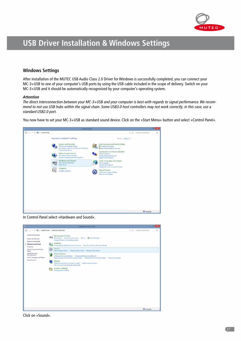
After installation of the MUTEC USB Audio Class 2.0 Driver for Windows is successfully completed, you can connect your MC-3+USB to one of your computer’s USB ports by using the USB cable included in the scope of delivery. Switch on your MC-3+USB and it should be automatically recognoized by your computer‘s operating system.
Attention The direct interconnection between your MC-3+USB and your computer is best with regards to signal perfermance. We recom-mend to not use USB hubs within the signal chain. Some USB3.0 host controllers may not work correctly, in this case, use a standard USB2.0 port.
You now have to set your MC-3+USB as standard sound device. Click on the »Start Menu« button and select »Control Panel«.
USB Driver Installation & Windows Settings
17
In Control Panel select »Hardware and Sound«.
Click on »Sound«.
USB Driver Installation & Windows Settings
18
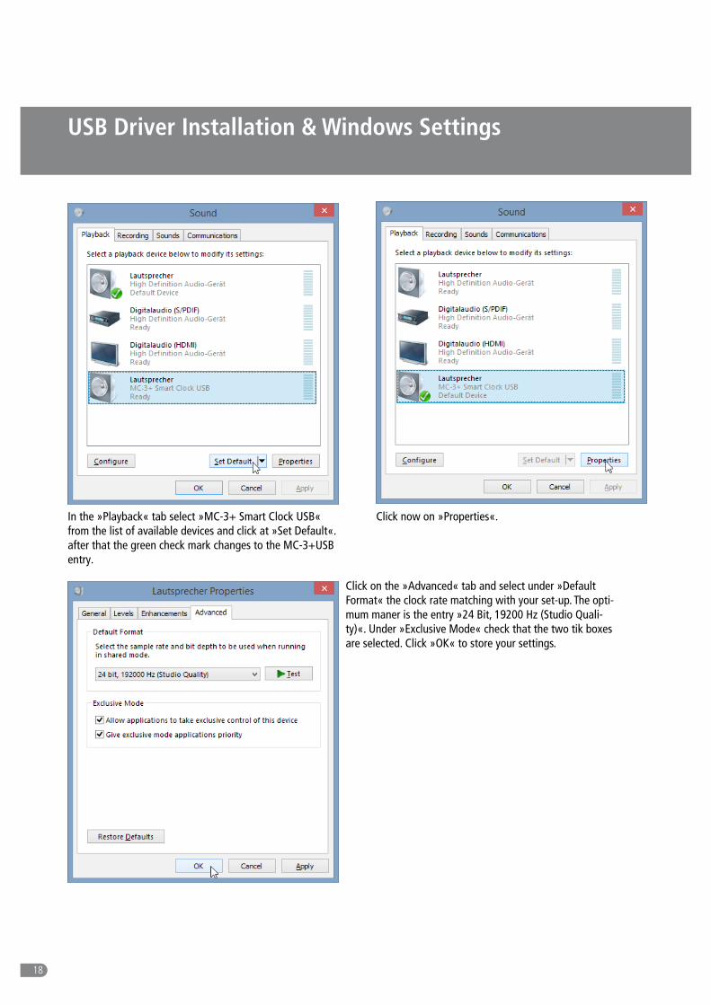
In the »Playback« tab select »MC-3+ Smart Clock USB« from the list of available devices and click at »Set Default«. after that the green check mark changes to the MC-3+USB entry.
Click now on »Properties«.
Click on the »Advanced« tab and select under »Default Format« the clock rate matching with your set-up. The opti-mum maner is the entry »24 Bit, 19200 Hz (Studio Quali-ty)«. Under »Exclusive Mode« check that the two tik boxes are selected. Click »OK« to store your settings.

Operation
19
General System Operation
Operating the MC-3+USB is very easy! The device is fully operated using the two keys on the front panel.
»MENU« Key Pressing the »MENU« key toggles between different basic function menus, usually between the vertical LED columns.
»SELECT« Key Pressing the »SELECT« key activates individual functions within one menu by toggling between the LEDs of one vertical LED column.
First press on »MENU« or »SELECT« key enables the last selected function within the last selected menu. The appropriate LED starts flashing. Every press on »SELECT« key will select a new function within the menu and the LED flashes accordingly. After a period of approx. 4 seconds the LED of the selected function stops flashing and the function is activated.
The »STATUS« and »CLOCK IN« menus are not accessible for adjustments. For further descriptions see page 22 under Status Information.
General Operation Procedure The menu of your MC-3+USB is strictly organized aligned to general handling procedures when inserting the MC-3+USB into your studio set-up. Thus, you can split up all of the necessary adjustments in three steps only, which leads to the following three questions for the basic operation of your MC-3+USB:
1) Which operation mode is basically needed? → »MODE«
Should my MC-3+USB work as clock generator (»INTERN«), as clock distributor (»EXTERN«) or as audio signal re-clocker (»RE-CLK«)?
2) Which reference do I need for my clocking application? → »REFERENCE«
3) Do I need different clock rates at the same time? → »CLOCK MULTIPLIERS«
After you’ve made these general decision regarding the operational mode, your MC-3+USB is now all set up for the best-possi-ble integration within your system. Because the user interface only allows useful combinations of functions, accidental misuse of the unit is virtually impossible. Let’s now have a look at the specific modes of operations and functions.
32.0
48.0
44.1
88.2
96.0
176.4
192.0
REFERENCE
WCLK
1–10.0MUSB-PCM
AES3/11S/P-DIF BNC AES3/11id
S/P-DIF OP USB-DSD/DoP
CLOCK OUT
MODE
INTERN
RE-CLK
EXTERN
CLOCK MULTIPLIERS
1 2 3 4×1
×8
×4
×2×256 SC
×512
×256 WC

Operation
20
Operation of the MC-3+ Smart Clock USB
Main Function Menus The four main function menus provide access to all features of your MC-3+USB.
Select the operational mode of the MC-3+USB via the »MODE« menu. This needs to be selected first. The factory default is »INTERN«.
The »REFERENCE« menu allows selecting the individual inputs of the MC-3+USB. That means, herewith all possible external references and the references for synchronous and externally referenced re-clocking may be activated for synchronization. The factory default is 44.1 kHz.
The »CLOCK OUT« menu allows selecting the basis clock rate for the Word Clock, AES3/11 and S/P-DIF outputs. It is accessible when running the MC-3+USB in the »INTERN« mode and when »1–10.0 M« or »USB-PCM and »USB-DSD/DoP« is selected within the »REFERENCE« menu. The factory default is set to 44.1 kHz.
Additional clock multipliers for each for the two Word Clock pairs and the digital audio outputs may be selected in the »CLOCK MULTIPLIERS« menu. Their numbering legend is assigned to the output numbers on the rear panel. Select the preferred output with the »MENU« key and toggle to the desired multiplier by pressing the »SELECT« key. The factory default is set to x1.
The »STATUS« and »CLOCK IN« menus serve system status monitoring purposes of the MC-3+USB only. They are not accessible for user adjustments.
Attention Shut-Down of outputs All digital outputs are muted while the function menus are active. After a function has been selected and the corresponding LED stops flashing, the digital outputs are activated for signal transfer.
User settings All user function settings will be stored and recalled when the unit is power-cycled.
»INTERN« – Selecting the internal Clock The MC-3+USB runs as a clock generator and is locked to its internal ultra-low jitter master clock. The base clock rate for all outputs can be selected in the »CLOCK OUT« menu.
The example above shows that the MC-3+USB is locked to its internal ultra-low jitter master clock, which provides a clock rate of 44.1 kHz to all of the available clock and audio outputs (= factory default). The »CLOCK OUT« menu allows setting the base clock rate of all the outputs to frequencies between 32.0 kHz and 192.0 kHz, which will be indicated by one or two LEDs. The »CLOCK MULTIPLIERS« menu provides access to selecting several clock multipliers for the Word Clock (1&2), S/P-DIF (3), and AES3/11 (4) outputs as described in the section »Selecting clock multipliers«. The current lock status of the frequency synthesi-zer for the internal clock rate will be shown in the »STATUS« menu, while the »CLOCK IN« section reflects the base clock rate selected in the »CLOCK OUT« menu.
The »REFERENCE« menu is deactivated in »INTERN« mode.
CLOCK MULTIPLIERS
1 2 3 4
MODE
32.0
48.0
INTERN
RE-CLK
EXTERN
×1
×8
×4
×244.1
88.2
96.0 ×256 SC
×512
×256 WC176.4
192.0
REFERENCE CLOCK OUT
WCLK
1–10.0MUSB-PCM
AES3/11S/P-DIF BNC AES3/11id
S/P-DIF OP USB-DSD/DoP
STATUS
LOCK MAIN REF
LOCK RE-CLK REF
CLOCK IN
32.0
48.0
DoP
AUDIO
HOLD
44.1
DSD
88.2
64
128
96.0
176.4
192.0256
1–10.0M
Operation
21
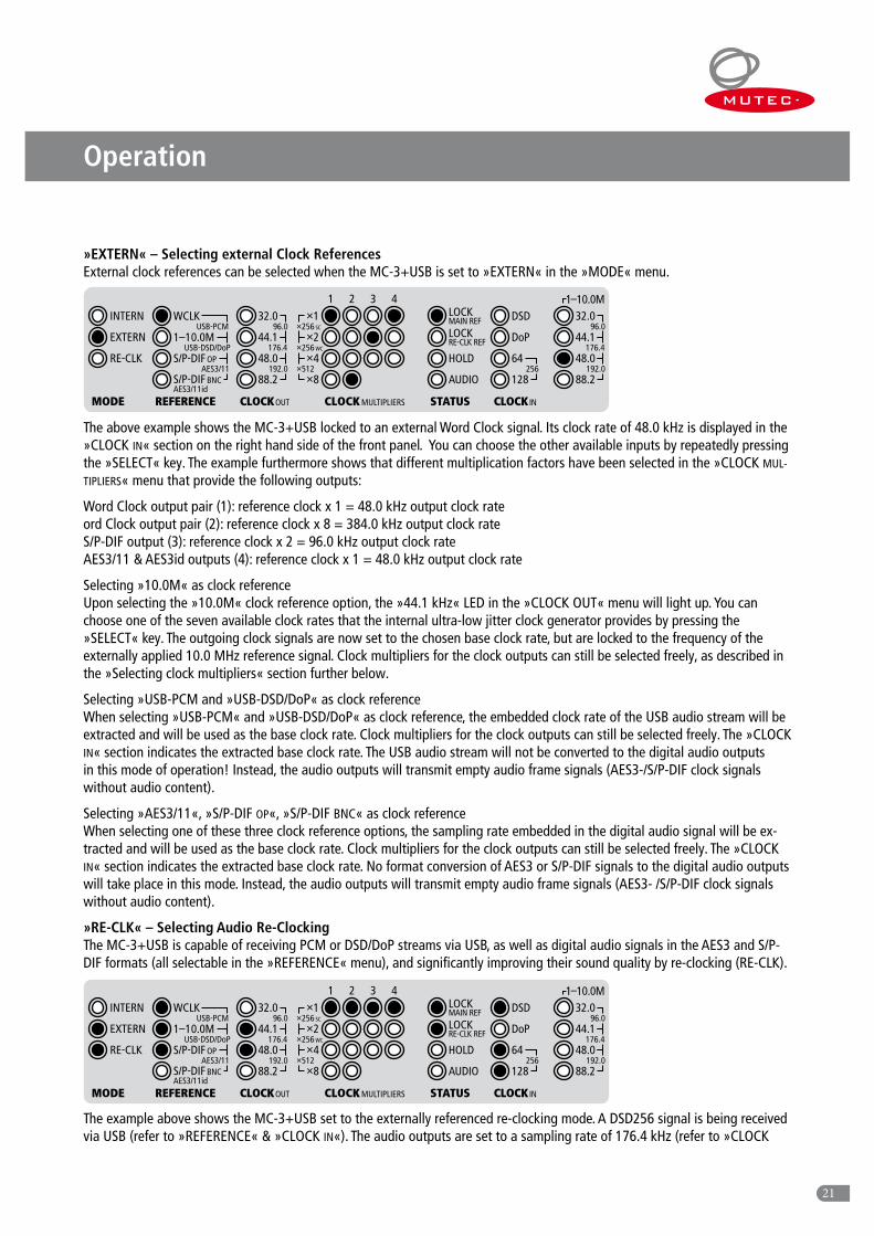
»EXTERN« – Selecting external Clock References External clock references can be selected when the MC-3+USB is set to »EXTERN« in the »MODE« menu.
The above example shows the MC-3+USB locked to an external Word Clock signal. Its clock rate of 48.0 kHz is displayed in the »CLOCK IN« section on the right hand side of the front panel. You can choose the other available inputs by repeatedly pressing the »SELECT« key. The example furthermore shows that different multiplication factors have been selected in the »CLOCK MUL-
TIPLIERS« menu that provide the following outputs:
Word Clock output pair (1): reference clock x 1 = 48.0 kHz output clock rate ord Clock output pair (2): reference clock x 8 = 384.0 kHz output clock rate S/P-DIF output (3): reference clock x 2 = 96.0 kHz output clock rate AES3/11 & AES3id outputs (4): reference clock x 1 = 48.0 kHz output clock rate
Selecting »10.0M« as clock reference Upon selecting the »10.0M« clock reference option, the »44.1 kHz« LED in the »CLOCK OUT« menu will light up. You can choose one of the seven available clock rates that the internal ultra-low jitter clock generator provides by pressing the »SELECT« key. The outgoing clock signals are now set to the chosen base clock rate, but are locked to the frequency of the externally applied 10.0 MHz reference signal. Clock multipliers for the clock outputs can still be selected freely, as described in the »Selecting clock multipliers« section further below.
Selecting »USB-PCM and »USB-DSD/DoP« as clock reference When selecting »USB-PCM« and »USB-DSD/DoP« as clock reference, the embedded clock rate of the USB audio stream will be extracted and will be used as the base clock rate. Clock multipliers for the clock outputs can still be selected freely. The »CLOCK IN« section indicates the extracted base clock rate. The USB audio stream will not be converted to the digital audio outputs in this mode of operation! Instead, the audio outputs will transmit empty audio frame signals (AES3-/S/P-DIF clock signals without audio content).
Selecting »AES3/11«, »S/P-DIF OP«, »S/P-DIF BNC« as clock reference When selecting one of these three clock reference options, the sampling rate embedded in the digital audio signal will be ex-tracted and will be used as the base clock rate. Clock multipliers for the clock outputs can still be selected freely. The »CLOCK IN« section indicates the extracted base clock rate. No format conversion of AES3 or S/P-DIF signals to the digital audio outputs will take place in this mode. Instead, the audio outputs will transmit empty audio frame signals (AES3- /S/P-DIF clock signals without audio content).
»RE-CLK« – Selecting Audio Re-Clocking The MC-3+USB is capable of receiving PCM or DSD/DoP streams via USB, as well as digital audio signals in the AES3 and S/P-DIF formats (all selectable in the »REFERENCE« menu), and significantly improving their sound quality by re-clocking (RE-CLK).
The example above shows the MC-3+USB set to the externally referenced re-clocking mode. A DSD256 signal is being received via USB (refer to »REFERENCE« & »CLOCK IN«). The audio outputs are set to a sampling rate of 176.4 kHz (refer to »CLOCK
CLOCK MULTIPLIERS
1 2 3 4
MODE
32.0
48.0
INTERN
RE-CLK
EXTERN
×1
×8
×4
×244.1
88.2
96.0 ×256 SC
×512
×256 WC176.4
192.0
REFERENCE CLOCK OUT
WCLK
1–10.0MUSB-PCM
AES3/11S/P-DIF BNC AES3/11id
S/P-DIF OP USB-DSD/DoP
STATUS
LOCK MAIN REF
LOCK RE-CLK REF
CLOCK IN
32.0
48.0
DoP
AUDIO
HOLD
44.1
DSD
88.2
64
128
96.0
176.4
192.0256
1–10.0M

22
Operation
OUT«) and will output the converted PCM signal of the DSD stream. Both lock indicators in the »STATUS« section are illumi-nated – the top LED indicates the lock to the DSD signal, while the bottom LED confirms synchronization to the external clock reference.
Two re-clocking modes are available: one based on the internal ultra-low jitter clock oscillator (»RE-CLK« & »INTERN«) and the other locked to an externally applied clock reference (»RE-CLK« & »EXTERN«).
»INTERN« & »RE-CLK« (Internally referenced Audio re-clocking) The »INTERN« and »RE-CLK« LEDs will light up when »RE-CLK« mode is selected, indicating that the re-clocking mode based on the internal clock oscillator is now active. As a factory default, »USB-PCM« and »USB-DSD/DoP« are selected as the first available audio reference in the »REFERENCE« menu (the first three LEDs in the column are illuminated). Press the menu key once and you’re entering the »REFERENCE« menu. Toggle the »SELECT« key to select one of the four available audio referen-ces: USB (PCM & DSD/DoP), AES3/11, S/P-DIF op, S/P-DIF bnc. This will now be re-clocked with the internal ultra-low jitter clock signal, format-converted, and passed on to all audio outputs with the same sampling rate simultaneously.
Attention Special use case: DSD/DoP as Audio Reference When selecting »USB-PCM« and »USB-DSD/DoP« as audio reference (first three LEDs light) in »INTERN & RE-CLK« or »EX-TERN & RE-CLK« mode, the MC-3+USB will convert a DSD or DoP signal to a PCM audio signal in real time. The converted PCM signal will then processed by the re-clocking algorithm and will be available at the different audio outputs. The original DSD/DoP streams will not be passed over to the outputs.
Furthermore, a sampling rate has to be selected for the PCM audio outputs in the »CLOCK OUT« menu. Switch to the »CLOCK OUT« menu by pressing the »MENU« key where you can choose between 44.1, 88.2, and 176.4 kHz. The same applies when the MC-3+USB is operating in the externally referenced re-clocking mode (see below).
»EXTERN« & »RE-CLK« (Externally referenced Audio re-clocking) This is a very unique feature that is only available in your MC-3+ Smart Clock USB! After selecting the first re-clocking mode, press the »SELECT« key once again and the »EXTERN« and »RE-CLK« will light up to indicate that re-clocking based on an externally applied clock reference is now active. Per default setting, »USB-PCM« and »USB-DSD/DoP« are selected as the first available audio reference (the first three LEDs in the column are illuminated). Press the »MENU« key once to access the »RE-FERENCE« menu and toggle the »SELECT« key to choose one of the four available audio references: USB (PCM & DSD/DoP), AES3/11, S/P-DIF op, S/P-DIF bnc.
Please note: the system will however expect an external re-clocking reference at the »WCLK & 1-10M IN« BNC input on the rear in this mode. If this reference is not provided, the re-clocking process will not be active. Possible re-clocking references are:
Word Clock 32.0 kHz – 192.0 kHz 1.0, 2.5, 5.0, 10.0 MHz
If both a valid audio and a re-clocking reference have been applied, the blue lock LEDs »MAIN REF« and »RE-CLK REF« in the »STATUS« section will light up and the re-clocking process will be started. The sampling rate of the incoming digital audio signal will be displayed in the »CLOCK IN« section of the front panel. The Word Clock output signals can be multiplied using the »CLOCK MULTIPLIERS« menu as described in the »Selecting Clock Multipliers« section.
Selecting one of these externally referenced re-clocking options enables re-clocking a digital audio signal with an external clock reference of a peripheral master clock generator. In all cases, the converted digital audio and Word Clock signals will have the same sampling rate as the digital audio source. However, there is no phase lock between input and output signals in this mode!
Attention Using external Clock References for Audio re-clocking If you’d like to use a Word Clock or 10.0 MHz clock reference for the externally referenced re-clocking, you should make sure that particularly the phase noise near the carrier frequency (1-100 Hz range from the carrier frequency at 10.0 MHz) is very low. Because of the extremely low noise signal processing of the MC-3+USB, there is a risk of audibly worse signal performan-ce if the externally applied clock reference is too noisy.
23
Operation
Different DoP Standards There are two different DoP code conventions. DSD data in a PCM stream will be identified with so called “markers”. The first (official) convention utilizes two alternating markers with the values 0x05 and 0xFA, also called DoP markers. The second convention uses a fixed marker with the value 0xAA, also called dCS marker. The MC-3+USB currently only supports the DoP marker convention.
Digital Audio Format Conversion When running the MC-3+USB in »RE-CLK« mode and applying a digital audio reference in the AES3 or S/P-DIF formats, all digital audio outputs will transmit the source signal. Those signals at the outputs which are not of the same format as the reference signal will be converted in real-time in compliance with the AES3 – 1992/2003 and IEC 60958 standards. As such, the MC-3+USB acts as a digital audio format converter!
Selecting Clock Multipliers Use the »MENU« key to navigate to the »CLOCK MULTIPLIERS« menu. Here you can select individual clock rate multiplication factors × 1, × 2, × 4, × 8, × 256 and × 512 for each Word Clock pair and (with limited options) for the digital audio outputs by toggling the »SELECT« key. The multipliers always refer to the base clock rate of the incoming reference signal or the selected clock rate of the internal ultra-low jitter clock generator (»CLOCK OUT«). Depending on the incoming or selected base clock frequency, the MC-3+USB is capable of covering 20 audio related clock rates from 32.0 kHz to 1.536 kHz, as well as 22.5792 MHz and 24.576 MHz, and the two so-called Super clocks at 11.2896 MHz and 12.288 MHz.
Selecting the »× 256 SC«, »× 256 WC«, and »× 512« clock multipliers The »× 256 SC« setting, the so called Super Clock, was included for clocking older digidesign ProToolsTM systems and will be transmitted at both Word Clock output pairs with the appropriate dedicated output level. Depending on the base clock rate (44.1 kHz or 48.0 kHz) of the received or generated reference clock signal, the outputs will transmit a clock rate of 11.2896 MHz (44.1 kHz × 256) or 12.2880 MHz (48.0 kHz × 256).
Using the »× 256 WC« setting, the system will output the same clock signals as described above, but now with the standard Word Clock output level.
Selecting the »× 512« setting will provide the highest possible clock rates of the MC-3+USB at 22.5792 MHz and 24.576 MHz. These were intended for clocking particular digital audio interfaces such as the hiFace EVO by M2Tech or devices by Esoteric Audio such as the Grandioso D1, P1, P-02, K-05, K-05X, K-07, K-07X, as well as devices by TACT Audio.
Attention Multiplying Digital Audo Signals When a digital audio input has been selected as reference and one or both multiplication factors are set higher than × 1, the MC-3+USB will only output black frame signals (AES3 and S/P-DIF signals without audio content) at the audio outputs. A sam-pling rate conversion of the incoming digital audio signal will not be carried out!
Sampling Rate Limit of the Digital Audio Outputs The multiplication of the S/P-DIF (»3«) and AES3/11(»4«) digital audio outputs is limited to a maximum sampling rate of 192.0 kHz regardless of the clock rate of the reference signal.

24
Operation
Status Information
The »STATUS« and »CLOCK IN« sections are strictly for monitoring the operational status of the MC-3+USB. They are not acces-sible for user adjustments via the keys.
STATUS »LOCK MAIN REF« & »LOCK RE-CLK REF« The blue LED »LOCK MAIN REF« illuminates when the internal PLL circuit has detected a valid clock reference in the inco-ming clock, audio or USB stream signals. If the incoming signal is unstable or lost, the »LOCK MAIN REF« LED is not lit. The blue »LOCK RE-CLK REF« illuminates when the MC-3+USB is set to the externally referenced re-clocking mode (»RE-CLK« & »EXTERNAL«) and the internal PLL circuit has detected a valid clock reference. Again, the »LOCK RE-CLK REF« will not be lit in case of signal instabilities.
»HOLD« This red LED is lit when the external reference clock, audio signal or USB audio stream has been interrupted or lost. The fre-quency synthesizer of the MC-3+USB continues to generate all output clock signals based on the last valid incoming clock rate. Thus, your studio setup will receive a steady, disruption-free clock signal regardless of whether a valid external reference signal is present, unstable or potentially damaged. Once an external clock reference returns and has been detected as valid, re-syn-chronization is carried out without critically affecting or disrupting any of the output signals.
»AUDIO« This red LED is lit when a valid AES3/11 or S/P-DIF optical or coaxial digital audio reference signal has been detected at the corresponding input.
CLOCK IN The first vertical row of LEDs in the »CLOCK IN« section indicates eligible DSD/DoP clock rates. These are:
DSD64, DSD128, DSD256 DoP64, DoP128
The second vertical row of LEDs in the »CLOCK IN« section is used to indicate eligible Word Clock, audio, and USB-PCM clock rates (refer to page 23).
Generic FunctionsThere are two additional functions which influence the working of your whole MC-3+USB:
32.0 kHz 44.1 kHz 48.0 kHz 88.2 kHz 96.0 kHz
176.4 kHz 192.0 kHz
Supported Clock Rates for Word-Clock-, Audio- and USB-PCM Input Signals
12.2880 MHz11.2896 MHz1-10.0 MHz
25
Operation
Front Panel lock out + LED shut down When pressing both front panel keys together at one time, all LEDs will shut down except the »POWER« and »LOCK« LEDs. Additionally, the functions of both keys are also blocked to prevent unauthorized operation, which is important during e.g. live events.
During that state of operation, pressing only one of both keys let every appropriate LED light according the device‘s settings as long as the key is pressed. Thus, you can check easily the device‘s settings without unlocking the device finally.
To reactivate the keys and the LEDs, please press both keys for apperox. four seconds until all LEDs light again.
Factory Reset You can reset the operating system of your MC-3+USB to the initial status by switching on the unit while pressing the »MENU« key simultaneously.
26
Appendix
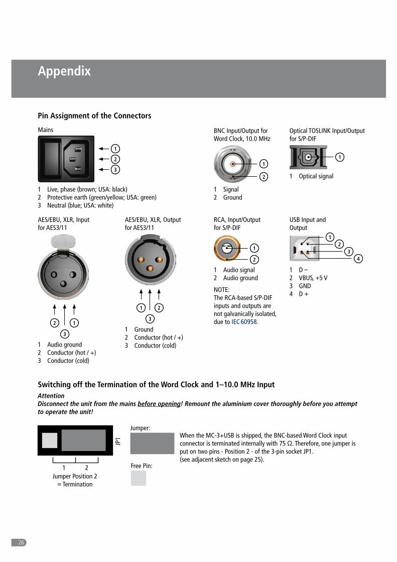
Pin Assignment of the Connectors
Mains
3
1 Live, phase (brown; USA: black) 2 Protective earth (green/yellow; USA: green) 3 Neutral (blue; USA: white)
2
1
USB Input and Output
1 D – 2 VBUS, +5 V 3 GND 4 D +
Switching off the Termination of the Word Clock and 1–10.0 MHz Input
Attention Disconnect the unit from the mains before opening! Remount the aluminium cover thoroughly before you attempt to operate the unit!
When the MC-3+USB is shipped, the BNC-based Word Clock input connector is terminated internally with 75 Ω. Therefore, one jumper is put on two pins - Position 2 - of the 3-pin socket JP1. (see adjacent sketch on page 25).
21
34
Optical TOSLINK Input/Output for S/P-DIF
1
1 Optical signal
BNC Input/Output for Word Clock, 10.0 MHz
1 Signal 2 Ground
1
2
2
3
1
1 Audio ground 2 Conductor (hot / +) 3 Conductor (cold)
AES/EBU, XLR, Input for AES3/11
RCA, Input/Output for S/P-DIF
1 Audio signal 2 Audio ground
1
2
1
3
2
1 Ground 2 Conductor (hot / +) 3 Conductor (cold)
AES/EBU, XLR, Output for AES3/11
NOTE: The RCA-based S/P-DIF inputs and outputs are not galvanically isolated, due to IEC 60958.
JP1
Jumper:
1 2 Free Pin:
Jumper Position 2 = Termination

27
Appendix
Inside View – Clock Input Termination
If you want to switch-off the termination, remove carefully the jumper from the two pins of position 2 of the socket and plug it onto the two pins of position 1 (see adjacent sletch).
Attention The jumper must be plugged on position one of the socket – do not omit him!
JP1
1 2Jumper Position 1 = no Termination
Word Clock & 1-10M Input
Termination3-pin socket JP1
S/P-DIF OPInput
MC-3+USB-Mainboard-
PCB

XX XX
28
USB In- & Output (USB I/O)Interface 1 x USB-B connectorFormats & Resolutions Type 1 Formats: PCM 16 bit, PCM 24 bit, PCM 32 bit, FLOAT 32 bit für USB 1.0 & USB 2.0Supported PCM Sampl. Rates USB 1.0: 44.1 kHz & 48.0 kHz, USB 2.0: 44.1 kHz to 192.0 kHzSupported DSD Sampl. Rates DSD64, DSD128, DSD256Supported DoP Sampl. Rates DoP64, DoP128Word Clock & 1–10.0 MHz Input (WCLK & 10.0M IN)Interface 1 x BNC, 200 mV-7 V, unbalanced, input impedance 75 Ω (can be switched off, see Page 24/25)Formats & Resolutions Word Clock, Word Clock × 256, so-called atomic clocks & GPS clock referencesSupported Clock Rates 32.0 kHz to 192.0 kHz, 1,0-, 2,5-, 5,0-, 10.0 MHz, 11.2896 MHz, 12.2880 MHzAES3/11 Input (AES3/11 IN)Interface 1 x XLR female, transformer balanced, input impedance 110 Ω, 200 mV–7.0 VFormats & Resolutions AES3-1992/2003, AES11-1997/2003, IEC 60958, 16–24 bitsSupported Sampling Rates 32.0 kHz to 192.0 kHzS/P-DIF & AES3id Input (S/P-DIF & AES3id IN)Interface 1 x BNC, 200 mV-7 V, unbalanced, input impedance 75 Ω Formats & Resolutions S/P-DIF: IEC 60958, 16 –24 bits, AES3id: AES3id-2001 (rev. 1995) or AES11-2003 (rev. 1997)Supported Sampling Rates 32.0 kHz to 192.0 kHzS/P-DIF optischer Input (S/P-DIF IN, OP)
Technical Data
Interface 1 x ToslinkTM, EIAJ RC-5720Formats & Resolutions IEC 60958, 16–24 bitsSupported Sampling Rates 32.0 kHz to 192.0 kHzWord Clock Outputs (WCLK OUT 1–2)Interface 1 x BNC, 200 mV–7 V, unbalanced, input impedance 75 ΩFormats & Resolutions Word Clock, Word Clock × 256, so-called »Super Clock«Supported Clock Rates 32.0 kHz to 192.0 kHzAES3/11 Output (AES3/11 OUT 4)Interface 1 x XLR male, transformer balanced, 3.5Vpp @ 110Ω, output impedance 110 Ω, bufferedFormats & Resolutions AES3-1992/2003, AES11-1997/2003, IEC 60958, 16–24 bitsSupported Sampling Rates 44.1 kHz to 192.0 kHzAES3id Output (AES3/11id OUT 4)Interface 1 x BNC, 1 V, unbalanced, input impedance 75 Ω, bufferedFormats & Resolutions AES3id: AES3id-2001 (rev. 1995) or AES11-2003 (rev. 1997), 16 -24 bitsSupported Sampling Rates 44.1 kHz to 192.0 kHzS/P-DIF BNC Output(S/P-DIF OUT 3)Interface 1 x BNC, 0.5 V, unbalanced, input impedance 75 Ω, bufferedFormats & Resolutions IEC 60958, 16–24 bitsSupported Sampling Rates 44.1 kHz to 192.0 kHzS/P-DIF optical Output (S/P-DIF OUT 3, OP)Interface 1 x ToslinkTM, EIAJ RC-5720Formats & Resolutions IEC 60958, 16–24 bitsSupported Sampling Rates 44.1 kHz to 192.0 kHzS/P-DIF RCA Output (S/P-DIF OUT 3, CO)Interface 1 x Coaxial (RCA female), unbalanced, 0.5 Vpp @ 75 Ω, output impedance 75 Ω, bufferedFormats & Resolutions IEC 60958, 16–24 bitsSupported Sampling Rates 44.1 kHz to 192.0 kHz
Appendix
XX XX
29
Appendix
Signal ProcessingWord Clock + AES11 conversion in every combination and direction
Digital Audio Format & AES3 + AES11 + S/P-DIF (optical + coaxial) conversion in every combination and directionClock Signal Conversion 10.0 MHz to Word Clock and AES11 conversion
Digital audio re-clocking, internally- and externally-referencedGalvanic USB Isolation 2500 V RMS aligned to UL1577, 4242 V PK aligned to DIN EN 60747-5-2 (VDE 0882, part 2)Frequenzsynthese & Referenztakt SpezifikationenFrequency Synthesis MUTEC’s propritary 1G-Clock Technology based on highest-clocked DDS processOscillator Type XO, digitally-compensated crystal oscillatorClock Accuracy (shipped) < ± 1.0 ppmClock Jitter < 1 ps (RMS)Operating Temperature 0 °C to + 50 °CPower SupplyType Internal, switching power supplyInput Voltage 85 V – 264 V (automatic adjustment), 47 Hz – 440 HzPower Consumption max. 10 WSystem Unit CoverCover Size / Material / Color 196 x 42 x 156 mm w/o connectors (W x H x D), steel sheet 1mm, matte-black powder-coatedFront Panel Size / Material 198 x 44 x 4 mm (W x H x D), aluminum, aluminum- or black-coloredWeight ~ 1350 gMC-3+ Smart Clock USB Order InformationFront aluminum-colored Item No. 8015-102, EAN Code: 4260342460542Front black-colored Item No. 8015-103, EAN Code: 4260342460559
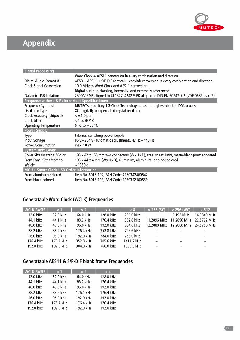
Generatable Word Clock (WCLK) Frequencies
WCLK BASIS × 1 × 2 × 4 × 8 × 256 (SC) × 256 (WC) × 51232.0 kHz 32.0 kHz 64.0 kHz 128.0 kHz 256.0 kHz – 8.192 MHz 16,3840 MHz44.1 kHz 44.1 kHz 88.2 kHz 176.4 kHz 352.8 kHz 11.2896 MHz 11.2896 MHz 22.5792 MHz48.0 kHz 48.0 kHz 96.0 kHz 192.0 kHz 384.0 kHz 12.2880 MHz 12.2880 MHz 24.5760 MHz88.2 kHz 88.2 kHz 176.4 kHz 352.8 kHz 705.6 kHz – – –96.0 kHz 96.0 kHz 192.0 kHz 384.0 kHz 768.0 kHz – – –176.4 kHz 176.4 kHz 352.8 kHz 705.6 kHz 1411.2 kHz – – –192.0 kHz 192.0 kHz 384.0 kHz 768.0 kHz 1536.0 kHz – – –
Generatable AES11 & S/P-DIF blank frame Frequencies
WCLK BASIS × 1 × 2 × 432.0 kHz 32.0 kHz 64.0 kHz 128.0 kHz44.1 kHz 44.1 kHz 88.2 kHz 176.4 kHz48.0 kHz 48.0 kHz 96.0 kHz 192.0 kHz88.2 kHz 88.2 kHz 176.4 kHz 176.4 kHz96.0 kHz 96.0 kHz 192.0 kHz 192.0 kHz176.4 kHz 176.4 kHz 176.4 kHz 176.4 kHz192.0 kHz 192.0 kHz 192.0 kHz 192.0 kHz

MUTEC GmbH · Fon 0049- (0)30-74 68 80-0 · contact@mutec-net .com · www.mutec-net .com
facebook.com/mutecpro pinterest .com/mutecpro https : / /p lus.google.com/116705378800155548696