operating manual - reiter-oft.de · operating manual rcc brush – air cap cleaning unit for robot...
TRANSCRIPT

REITER GmbH + Co. KG Oberflächentechnik Phone: +49 (0) 71 95 / 185 - 0Berglenstraße 23 - 25 Telefax: +49 (0) 71 95 / 185 - 30D-71364 Winnenden Internet: www.reiter-oft.de
Operating ManualRCC Brush – Air Cap Cleaning Unit for Robot Application
Type: PRS-00Issue: 09/14 - 4 (GB Tranlsation)

6710/PRS-00gb 09/14 - 4 Page 2 of 21
RCC Brush
Table of Contents
1.0 General danger and warning information ..........................................................................31.1 About this operation manual ..............................................................................................41.2 Explanation of symbols and information ............................................................................41.2.1 Symbol for occupational safety ..........................................................................................41.2.2 Attention .............................................................................................................................41.3 Air cap cleaning unit PRS-00 (RCC Brush) .......................................................................51.4 Product liability and guarantee...........................................................................................51.4.1 Exclusion of Application .....................................................................................................51.4.2 Guarantee ..........................................................................................................................51.4.3 Copyright............................................................................................................................6
2.0 Correct use ........................................................................................................................72.1 Application .........................................................................................................................72.2 Coating material/cleaning agents.......................................................................................72.3 Safety measurements ........................................................................................................72.4 Suitable premises ..............................................................................................................72.5 Electro-magnetic valve.......................................................................................................82.6 General requirements for safe operation ...........................................................................82.7 Instruction ..........................................................................................................................82.8 Deployment of the cap cleaner in potentially explosive atmospheres ...............................82.9 Workplaces ........................................................................................................................82.10 Cleaning .............................................................................................................................92.11 Essential condition for entering spray booths ....................................................................92.12 Personal protective equipment ..........................................................................................92.13 Work in areas with ignition hazards ...................................................................................92.14 Explosion protection document ........................................................................................10
3.0 Set up and function ..........................................................................................................10
4.0 Assembly ......................................................................................................................... 11
5.0 Commissioning ................................................................................................................125.1 Connection diagram .........................................................................................................125.2 Function and setting.........................................................................................................13
6.0 Cleaning, maintenance and care .....................................................................................146.1 Maintenance intervals ......................................................................................................146.1.1 Assembly and Disassembly .............................................................................................156.1.2 Zig-zag system when changing the cover of the roller brush ..........................................166.1.3 Exchange of the pressurized-air hose .............................................................................176.1.4 Exchange of solvent from brush container.......................................................................176.1.5 Exchange of the air motor ................................................................................................186.1.6 Exchange of the tappet valves .........................................................................................196.2 Troubleshooting ...............................................................................................................20
7.0 Technical data ..................................................................................................................217.1 Parts touched by material ................................................................................................217.2 Marking ............................................................................................................................21

6710/PRS-00gb 09/14 - 4 Page 3 of 21
RCC Brush
max. level
min. level
Picture 1
1.0 General danger and warning information • Assemblyofaircapcleaningunitandconnectingofcompressedairmustbeperformedbyex-
pert personnel only.
• Fasteningpointsandconnectorsneedtobecheckedfromtimetotime.
• Whileworking,cleaning,performingmaintenanceandrepairworkorchangingusedcleaningagents, the protective gear recommended by the supplier has to be worn at all times (gloves, safety glasses, protective clothing etc.).
• Securitybootsneedtobeantistatic.
• Itisnotguaranteedthatthosepartsoftheaircapcleaningunitincontactwithmaterialarecompatible with all coating materials or cleaning agents (see “Technical Data – Parts touched byMaterial“).Incasesofdoubt,contactREITERGmbH+Co.KGOberflächentechnik
• Adequategroundinghastobeprovidedforexampleconnectionofthegroundingfrombuildingtothesupport.Heatingequipmentandwaterpipesdonotprovidesufficientgrounding.
• Incaseofinterruptionofoperation,shuttingdown,aswellaspriortodisassembly,repair-andmaintenance work, the air cap cleaning unit must not be under pressure. The air supply must be turned off, pressure has to be released.
• Priortorepeatedcommissioningconnectionsandsettingsmustbecheckedandtheaircapcleaning unit must be checked for leakage (no uncontrolled draining of air or cleaning agent).
• Asstatedin“TechnicalData“,themaximumpressureandtemperaturemustnotbeexceeded.
• Don’treachintotherotatingbrushes.Dangerofcrushing!
• Thesupplycontainerforcleaningagentsmustnotbefilledabovethemaximumlevelmarking(seepicture1).Otherwisetheexcessivecleaningagentwilloverflowduringthebrushingpro-cess.
• Toavoiddryrunningoftherollerbrushthesupplycontainerhastobefilledatleasttothelowermarking (see picture 1).

6710/PRS-00gb 09/14 - 4 Page 4 of 21
RCC Brush
!
• Wearingpartsneedtobecheckedinadequatetimeintervalsandneedtobeexchangedifnecessary.
• UseonlyREITERGmbH+Co.KGOberflächentechnikspareandsupplyparts.REITERGmbH+Co.KGOberflächentechnikwillnotbeliablefordamagesifotherthanREITERGmbH+Co.KGOberflächentechnikpartsarebeingused.
• Commissioningofaircapcleaningunitonlywhenlidisattached.
Note: The air cap cleaner is operated with pneumatics and controlled by electromagnetic valves. These are not part of the scope of supply.
Endangerment above the usual extent is not known when using the air cap cleaning unit. However, if an accident or accident-prone situation should occur, we ask you to get in touch with us.
1.1 About this operation manual • ThisoperationmanualappliesonlytotheaircapcleaningunitPRS-00.
• Allinformationcontainedinthisoperationmanualisonlyvalidtogettoknowtheaircapclean-er and its components in a typical working environment. This is not a manual for initial opera-tion, because every plant is different. For initial operation it is vital that authorized personnel of REITERGmbH+Co.KGOberflächentechnikperformsanintroduction.
• ThisoperationmanualcontainsinformationaboutoperationandmaintenanceofthisREITERGmbH+Co.KGOberflächentechnikcapcleanerinatypicalplantconfiguration.Allhereingiven technical data and procedures are standard data and procedures and can differ from the different installations.
• Forabetterunderstandingofthiscapcleanerandforattaininganoptimallong-termandfault-free operation this operation manual has to be read carefully and thoroughly.
• Allgiventestandexaminationshavetobeperformedpriortocallingaservicetechnician.Inany case, this call for a service technician should be performed by person who is used to oper-ate this equipment and keeps this operation manual on hand.
1.2 Explanation of symbols and information
1.2.1 Symbol for occupational safetyIn this operation manual this symbol is used for all information about occupational safety, when danger for life and limb can occur due to non-observance of information of this operation manual. Please ob-serve these information and act especially careful. Also give this infor-mation to other users. Next to this operation manual all other general safety- and accident prevention regulations have to be observed as well.
1.2.2 AttentionInthisoperationmanualthisAttention!standsnexttopassages,whichhave to be read very carefully, to comply with rules, regulations, notes, and the correct operation procedure and to prevent damages and de-structions of the machinery and/or other parts of the plant.
Attention!

6710/PRS-00gb 09/14 - 4 Page 5 of 21
RCC Brush
1.3 Air cap cleaning unit PRS-00 (RCC Brush)The air cap cleaning unit in general consists of:
• Cleaningroller
• Tappetvalves
• Cleaningcontainerwithlid
• Pressurized-airhoses
Note The needed electro-magnetic valves for the control of the air cap cleaning unit are not part of the scope of supply.
1.4 Product liability and guaranteeImportant note about product liabilityBecause of a valid EC regulation from 01.01.1990 the manufacturer is only liable for his product when all parts are made from the manufacturer himself or are released by the manufacturer him-self, and all parts of the device are mounted and operated appropriate. When using purchased parts and/or accessories the liability can be omitted in whole or in part.
We,theREITERGmbH+Co.KGOberflächentechnik,arenottakinganyliabilityfordamagesoc-curring from one ore more of the following reasons:Unsuitableorimproperuse,useofpurchased,non-originalparts,faultyassemblyorcommission-ing by the buyer himself or by a third party, natural wear and tear as well as parts subject to wear, faulty operation and/or maintenance and non-observance of this operation manual.
1.4.1 Exclusion of ApplicationThe description of the plant does not apply to building- and construction operations of the build-ings or rooms, in which the cap cleaner shall be installed and operated. It is assumed that the cap cleaner will only be operated as part of a whole plant, which was erected according to building su-pervisory authorities and necessary measures for environmental protection.When mounting the cap cleaner all valid national safety regulations of the country concerned as well as the generally accepted regulations of technology have to be considered (see chapter 2.3 “Safety Guidelines“).
1.4.2 GuaranteePlease read this operation manual carefully and in whole, because REITER GmbH + Co. KG Ober-flächentechnikcannotbeheldliablefordamagesoccurringofnon-observationofthisoperationmanual.Duringthetimeofguaranteeallmaintenanceworkandmodificationsareonlyallowedtobe performed by our technicians or with our consent.
The Cap Cleaner is only designed for the use described in chapter 2.0 “Intended use“. Any addi-tional use is considered as “non intentional use“ and is excluded without limitation. If any damage occursduetoanyusedepartfromtheintendeduse,REITERGmbH+Co.KGOberflächentechnikcannot be held liable. In this case the operator takes the full risk.

6710/PRS-00gb 09/14 - 4 Page 6 of 21
RCC Brush
1.4.3 CopyrightThecopyrightofthisoperationmanualremainswithREITERGmbH+Co.KGOberflächentechnik.This operation manual is intended for assembly-, operation-, and controlling personnel and con-tains rules and technical drawings, which are not allowed to be copied and/or distributed in whole orinpart.Unauthorizedtransmissiontoorutilizationbythirdpartiesisprohibited.
REITER GmbH + Co. KGOberflächentechnik Phone: +49 (0) 71 95 / 185 - 0Berglenstraße 23 - 25 Fax: +49 (0) 71 95 / 185- 30D-71364 Winnenden Email: [email protected]

6710/PRS-00gb 09/14 - 4 Page 7 of 21
RCC Brush
2.0 Correct useThe air cap cleaning unit is utilized for the automatic cleaning of air caps of coating equipment. It is not suitable for the cleaning of manual spraying guns. Only allowed cleaning agents are to be used.
2.1 ApplicationThe air cap cleaning unit is being used as part of a fully automated robot painting installation inside a spaying booth. During its use the air cap cleaning unit has to be safeguarded against manual ac-cess.Theaircapcleaningunitiscertifiedfortheuseinhazardousareasofzones1and2.
2.2 Coating material/cleaning agentsIn the use of electrostatic application system is:Regardingemissions,fire,andexplosionhazardsaswellasotherdangers,thedangerandwarn-ing information provided by the suppliers of the coating materials respectively the cleaning agents, must be observed. In cases of doubt please contact the supplier.
Theaircapcleaningunitmayonlybecleanedwithcleaningagentswhoseflashpointisatleast5Khigher than the surrounding temperature. For example: If the temperature of the booth is 23°C the flashpointofthecleaningagenthastobeatleast28°C.Keepopenfireandotherignitionsourcesaway.
2.3 Safety measurementsWhen working with material whose explosion potential will increase through atomizing (for example whenbrushingwithflammablesolvents),precautionarymeasurementshavetobetakenandthatparticular danger has to be pointed out. In cases of doubt contact the suppliers of the components.
If the air cap cleaning unit is operated together with an electrostatic spraying system it has to be as-sured that after the high voltage has been turned off, all parts that come in contact with the air cap cleaning unit and the cleaning area (see 2.4) have to be discharged to less than 0,24 mJ (equals 60 nC). This has to be documented and revised on a regular basis.
2.4 Suitable premisesDuring the cleaning process (brushing) coating material and cleaning agents get in the surrounding air.Dependingonthecoatingmaterialandcleaningagent,environmental-,fire-,explosion-,andhazards to health might arise.
Therefore the air cap cleaning unit must only be operated in suitable premises (painting booth) with technical ventilation according to EN 12215. It has to be made sure that no cleaning agents can leave the cleaning area and reach the surrounding areas.
Cleaning area: 1m spheric surrounding the opening of the container with the cleaning brush.This also means that the maximum concentration of the used detergent inside the cleaning area shall not exceed 50% of the lower explosion level (LEL).The effectiveness of the technical ventilation has to be insured through special measures.

6710/PRS-00gb 09/14 - 4 Page 8 of 21
RCC Brush
2.5 Electro-magnetic valveThe electro-magnetic valves for the control of the air cap cleaning unit (build into the control cabi-net), which are not part of the scope of delivery, have to meet the requirements of the area in which they will be installed.
2.6 General requirements for safe operation • Forassuringasafeoperationoftheaircapcleaningunitanditsaccessorytheoperatoroblig-
es to create operating instructions/company rulings regarding this operation manual. These operating instructions have to be provided in a language the employees can understand and have to be published at a suitable place.
• Theseoperatinginstructionshavetocontainthenotethatthiscapcleanershallonlybeoper-ated by instructed staff.
• Awarningsignhastobeplacedatapositionnearthecleaningareainalanguagetheemploy-ees can understand. Such warning sign should have to indicate the most important methods of operation and safety instructions, which have to be respected by the employees, and shall be prominently displayed, completely implemented and accessible. It also has to contain the dangers occurring when spray guns are being cleaned.
2.7 InstructionPrior to the start of work with the cap cleaner it has to be assured that all persons working with the cap cleaner are instructed about the dangers and risks of working with the cap cleaner and its ac-cessory and about all measurements of avoiding these dangers and risks. This instruction has to be repeated at least once a year.
2.8 Deployment of the cap cleaner in potentially explosive atmospheresIt is only allowed to operate the cap cleaner when all protective measures against typical risks and dangers of work are taken. It also has to be assured that protective measures are taken against dangerous electrical shocks, using
• Suitableworkwear
• Electrostaticdissipativeworkboots
• Securingtheplantagainstaccidentalre-starting
• Securingthatallpressurehasbeenreleased
• Correctgrounding
2.9 Workplaces • Caremustbetakentoassurethatallignitionsourcesareavoided.Smokingandopenfireshall
be forbidden in all areas with potentially explosive atmospheres.
• Caremustbetakentoassurethatdepositsofcoatingmaterialareasminimalaspossibleinallspraying booths, spray cabins, at the cap cleaner itself and the whole workplace itself.
• Itmustbestressedoutandmonitoredthatallaccessdoorsareclosedduringthecleaningpro-cess.

6710/PRS-00gb 09/14 - 4 Page 9 of 21
RCC Brush
2.10 Cleaning • Depositsofcoatingmaterialhavetoberemovedinappropriateintervals.Caremustbetaken
to assure that the whole spray booth as well as all exhaust systems, varnish dust removers (if existing), and the surrounding areas are being cleaned.
• Caremustbetakentoassurethattechnicalventilationisswitchedonanoperationalduringcleaning procedures.
• Itisonlyallowedtouseelectricallyconductivecontainersforthecleaningliquids.Thesecon-tainers need to be grounded properly. It is not allowed to use plastic containers.
• Itisonlyallowedtousesolventswhichflashpointis5Khigherthatthesurroundingtempera-ture.
2.11 Essential condition for entering spray booths • Caremustbetakentoassurethattheconcentrationofsolventsisandstaysbelowthelimitof
health hazards.
• Caremustbetakentoassurethatthefloorofthesprayboothiselectrostaticconductive.
• Caremustbetakentoassurethatnopersonsarepresentduringtheautomatedcleaningpro-cess of the cap cleaner.
Additional prerequisites when using electrostatic spraying systems:
• Caremustbetakentoassurethatthedischargeenergyisbelow350mJwhenpartsofthehighvoltage circuit can be touched. The allowed time between the switch-off of high voltage and a possible contact with conductive parts has to be adapted to local conditions and operational requirements.
• Caremustbetakentoassurethatthemaximumdischargeenergyisbelow0.24mJ,whenus-ingflammablecleaningagents.
2.12 Personal protective equipment • Caremustbetakentoassurethatallpersonsintheareaoftheelectrostaticconductivefloor
are wearing antistatic footwear.
• Ifprotectiveglovesarenecessarytheseprotectivegloveshavetobeantistaticorprovidesimi-lar effects.
2.13 Work in areas with ignition hazards • Theoperatorhastoensurethatnoworkprovidingignitionhazardsarebeingcarriedoutin
areas with potentially explosive atmospheres and hazardous areas. Exceptions are possible when special precautions are being taken (e. g. removal of coating materials, solvents and otherflammableliquids,extensivecleaningofallplantsandareas,ensuringaproperventila-tion, …).
• Inareaswithopeningstoareaswithpotentiallyexplosiveatmospheresspecialcaremustbetaken to ensure that work with ignition hazards can only be carried out when the ignition sourc-es cannot reach the areas with potentially explosive atmosphere.

6710/PRS-00gb 09/14 - 4 Page 10 of 21
RCC Brush
2.14 Explosion protection documentAccording to directive 1999/92/EC the plant operator must provide an explosion protection docu-ment, containing the required risk assessment of explosive atmospheres, effective ignition sources, and an estimate of the scale of a potential explosion, irrespective of workforce numbers.
According to article 8 of 1999/92/EC the employer shall ensure that an explosion protection docu-ment is drawn up and kept up to date. This document shall demonstrate in particular
• thattheexplosionriskshavebeendeterminedandassessed
• thatadequatemeasureswillbetakentoattaintheaimsofdirective1999/92/EC
• thoseplaceswhichhavebeenclassifiedintozonesinaccordancewithAnnexIof1999/92/EC
• thoseplaceswheretheminimumrequirementssetoutinAnnexIIof1999/92/ECwillapply
• thattheworkplaceandworkequipment,includingwarningdevices,aredesigned,operated,and maintained with due regard for safety
• thatinaccordancewithCouncilDirective89/655/EECarrangementshavebeenmadeforthesafe use of work equipment.
The explosion protection document shall be drawn up prior to the commencement of work and be revisedwhentheworkplace,workequipmentororganizationoftheworkundergoessignificantchanges, extension, or conversions.
The employer may combine existing explosion risk assessments, documents, or other equivalent reports produced under other Community acts.
3.0 Set up and functionThe air cap cleaning unit consists mainly of a pneumatically driven roller brush that is located inside asupplycontainer–suitableforthefillingwithcleaningagents–andablowingringforblowingoffthe air caps after the brushing process. A pneumatically operated pivoting lid (optional) shuts the opening of the supply container lid when the brush drive is not in use.
Thecleaningagentshavetobefilledinmanually;aballvalveislocatedonthebottomsideofthesupply container for draining of the cleaning agents.
The pneumatic components necessary for the control of the brush drive are located centrally at the side of the tub under a splash guard cover.
The all over cleaning of the spraying equipment air cap is done by moving of the spraying equip-ment alongside the brush axis while the brush is simultaneously oscillating in 180° pivoting move-ments.

6710/PRS-00gb 09/14 - 4 Page 11 of 21
RCC Brush
4.0 AssemblyThe optional available support of the air cap cleaning unit is positioned according to the area of op-eration of the spraying equipment or spraying robot and fastened securely.
Note: Makesurepropergroundingisprovided!
If the air cap cleaning unit is not fastened adequately it could come loose during operation for example through vibration. Therefore the position of the brush will change. A safe moving of the brush through the spraying equipment is not guaranteed any longer. It is possible that the cleaning agent will drain uncontrolled.
Expert personnel must perform assembly only.
Attention!

6710/PRS-00gb 09/14 - 4 Page 12 of 21
RCC Brush
5.0 Commissioning5.1 Connection diagram
Expert personnel must perform pneumatic installation only. Pressure and temperatures listed in “Technical Data“ may not be exceeded.
Attention!

6710/PRS-00gb 09/14 - 4 Page 13 of 21
RCC Brush
+ –
5.2 Function and settingThe brush drive is turned on over an electric magnet valve (respectively for trial by manual opera-tion). The reverse of the oscillating 180° pivoting motion is caused by a micro ram valve, whereby the impulse valve is reversed.
The brush should make around 160 - 190 complete motions (back and forth) per minute. If the numbers of revolutions differ, they can be adjusted over the exhaust air restrictor valve: turning the slotscrewintheexhaustairrestrictorvalveclockwisewilldecreasethenumberofrevolutions;turn-ing the screw counter-clockwise will increase the number of revolutions.

6710/PRS-00gb 09/14 - 4 Page 14 of 21
RCC Brush
6.0 Cleaning, maintenance and care • Cleanallmetalsurfacesusingalintfreeclothandsomesuitablesolvent
• Removerawimpuritiesusinganon-sparkingtool
• Exchangepressurehosesifcontaminatedsevere
• Checksolventinsidethebrushcontainerforseverepollutionandlevel.Refillifnecessaryorexchange in whole. If an exchange is necessary place a metal container below the brush con-tainer, open the tap and let solvent drain completely. Afterwards remove the lid of the brush containerandcleanbrushcontainerandlid.Thenclosetapandrefilluptotheuppermarker.
• Thefasteningelementshavetobecheckedfromtimetotimeandtightened,ifnecessary.
• Wearingpartssuchastherollerbrush,radialrotaryshaftseal,slidebushetc.havetobechecked in appropriate time intervals and replaced, if necessary.
The air cap cleaning unit must not be disassembled for any other rea-son than repair work.
Prior to maintenance and repair work it has to be assured that the air cap cleaning unit is no longer under pressure (turn off air supply).
6.1 Maintenance intervalsWeekly
• Checkpressurehosesfordents,breaksandcracks(visibletest);ifpressurehosehasdents,cracks, breaks or pressure is leaking, exchange hose (6.1.3)
• Checktappetvalvesforcorrectfunction,exchangeifnecessary(6.1.6)
Monthly • Checkbrushforwear;ifbrushiswornoutexchangewithnewbrush(6.1.1)
Yearly • Checkwholecapcleanerforcorrectfunction,damages,andwear.Exchangepartsifneces-
sary.
• Cleanwholecapcleaner
On shift change • Checksolventinbrushcontainerforseverepollution.Ifnecessaryreleasesolvent,cleanbrush
container,closetapandrefilltouppermarking.
• Checklevelofsolventandrefillifnecessary.Theuppersolventlevelshallbeinbetweenthetwo markings on the inside of the brush container.
Attention!
6710/PRS-00gb 09/14 - 4 Page 15 of 21
RCC Brush
(c)
(d)
(e)
(f)
(a)
(b)
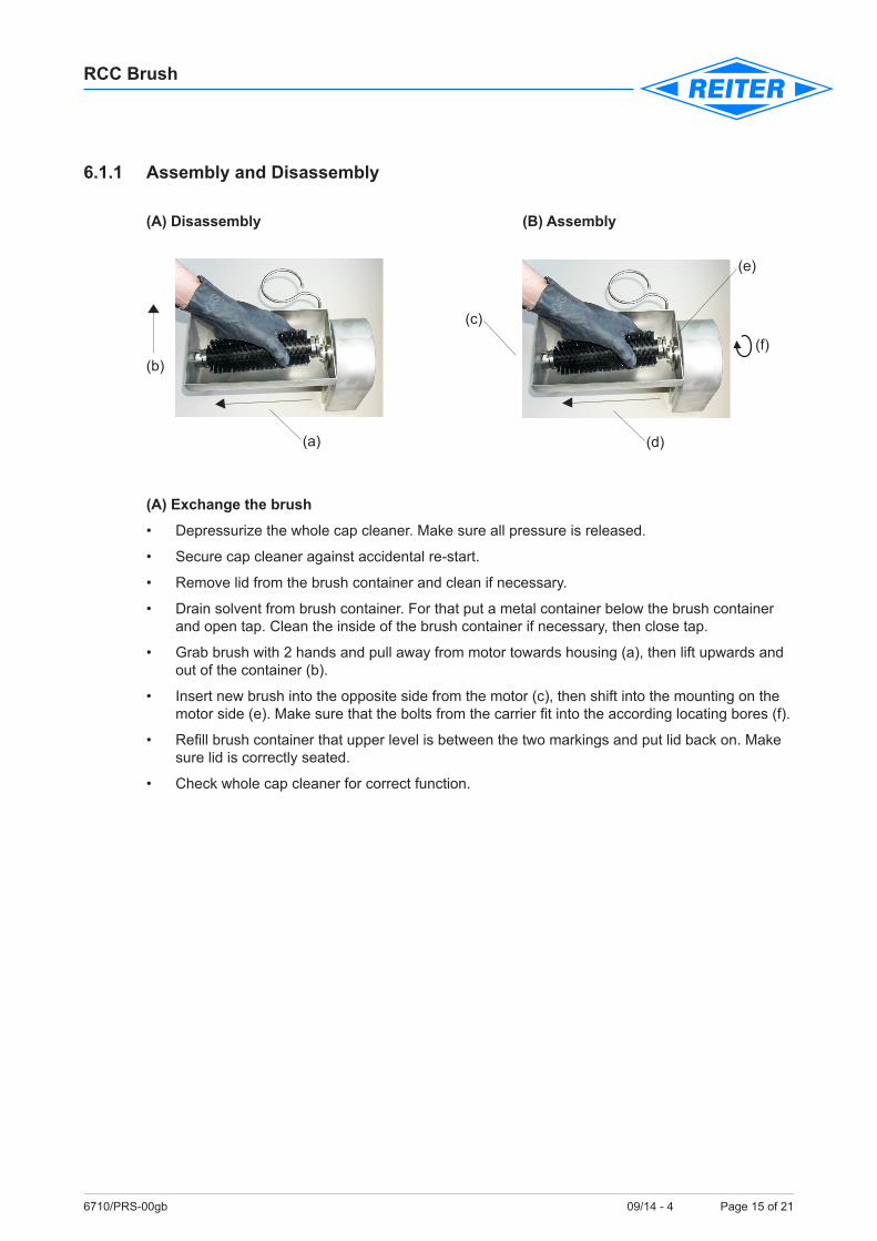
6.1.1 Assembly and Disassembly
(A) Disassembly (B) Assembly
(A) Exchange the brush
• Depressurizethewholecapcleaner.Makesureallpressureisreleased.
• Securecapcleaneragainstaccidentalre-start.
• Removelidfromthebrushcontainerandcleanifnecessary.
• Drainsolventfrombrushcontainer.Forthatputametalcontainerbelowthebrushcontainerand open tap. Clean the inside of the brush container if necessary, then close tap.
• Grabbrushwith2handsandpullawayfrommotortowardshousing(a),thenliftupwardsandout of the container (b).
• Insertnewbrushintotheoppositesidefromthemotor(c),thenshiftintothemountingonthemotorside(e).Makesurethattheboltsfromthecarrierfitintotheaccordinglocatingbores(f).
• Refillbrushcontainerthatupperlevelisbetweenthetwomarkingsandputlidbackon.Makesure lid is correctly seated.
• Checkwholecapcleanerforcorrectfunction.

6710/PRS-00gb 09/14 - 4 Page 16 of 21
RCC Brush
6.1.2 Zig-zag system when changing the cover of the roller brushThe zig-zag system makes it easy to install or change the cover of the roller brushes quickly:
• Thegearedsetcollarispushedontotheshaft.Attheendoftheshaftitistighteneddownwiththe help of two grub screws.
• Thetwozig-zagsegmentsarepushedoneafteranotherontheshaftandpressedhardagainstthe mounted set collar.
• Thenthesecondsetcollarispressedagainstthelastzig-zagelement,thegrubscrewsaretightened only slightly at the moment.
• Afterthatthesetcollarispressedagainstthezig-zagsegmentsbytappingaflatpieceofwoodwith a hammer on the outer face of the set collar.
• Assoonasatightfittingofthesegmentsisfelt,thegrubscrewsatthesecondsetcollararetightened down.
The zig-zag roller brush is immediately ready for operation. Reverse the above steps for disassem-bly.
Set collar remains on shaftBrush two-partsOpen set collar only here

6710/PRS-00gb 09/14 - 4 Page 17 of 21
RCC Brush
6.1.3 Exchange of the pressurized-air hose
• Depressurizethewholecapcleaner.Makesureallpressureisreleased.
• Securecapcleaneragainstaccidentalre-start
• Removethepressurized-airhosewhichneedstobeexchanged
• Cutnewpressurized-airhosetofittinglength
• Pressnewhoseintohosecoupling.Checkcorrectseatingwithslightpullingofthenewhose
• Afterexchangerestartcapcleanerandchecknewpressurized-airhoseandhosecouplingforleakages
6.1.4 Exchange of solvent from brush container • Removelidfrombrushcontainerandcleanifnecessary
• OpentapReleasesolventintoametalcontainer
• Cleaninsideofbrushcontainerwithnewsolvent.Forthatlettapopenthatsolventcandraininto metal container. Remove stained pollutions using a non-sparking tool.
• Afterprocessclosetapandrefillbrushcontainerthatupperlevelofsolventisbetweenthetwomarkings
• Putlidbackon

6710/PRS-00gb 09/14 - 4 Page 18 of 21
RCC Brush
6.1.5 Exchange of the air motor
• Depressurizethewholecapcleaner.Makesureallpressureisreleased.
• Securecapcleaneragainstaccidentalre-start.
• Removelidfrombrushcontainerandcleanifnecessary.
• Drainsolventfrombrushcontainer.Forthatputametalcontainerbelowthebrushcontainerand open tap. Clean the inside of the brush container if necessary, then close tap.
• Grabbrushwith2handsandpullawayfrommotortowardshousing(a),thenliftupwardsandout of the container (b).
• Checkbrushforwearandexchangeifnecessary(see6.1.1).
• Removebrushcarrierusingascrewdriver(Phillips2),cleanifnecessary,thenstoreinasafeplace.
• Removeprotectivelidfrommotorandcleanifnecessary.
• Removepressurized-airhosesfromairmotorandcheckforbreaks,cracksandleakages.Ex-change if necessary.
• Removethe2fasteningscrewsusinganAllenkey5mm.
• Removeairmotor.
• Re-insertanewair-motor;makesurethatitfitsexactly.
• Secureair-motorusingthe2fasteningscrewslooselyandcheckforcorrectseatingbeforefix-ing with an Allen-key 5mm tangible. Do not fix to tight!
• Remountbothbrushcarriers,usingascrewdriver(Phillips2).
• Remountbrushasdescribedunder6.1.1
• Rebuildallpressuredairconnections.
• Remountprotectivelidovermotor.
• Refillbrushcontainerwithsolventtillupperlevelofsolventisbetweenbothmarkersonthein-side of the brush container. Put cover back on.
• Checkwholecapcleanerforcorrectfunction.
Fastening screw Fastening screw

6710/PRS-00gb 09/14 - 4 Page 19 of 21
RCC Brush
6.1.6 Exchange of the tappet valves
• Depressurizethewholecapcleaner.Makesureallpressureisreleased.
• Securecapcleaneragainstaccidentalre-start.
• Removepressurized-airhosesfromtappetvalvesandcheckforwear,cracks,andbreaks.Ex-change if necessary.
• RemovethefasteningscrewsofthetappetvalvesusingaPhillips2screwdriver.
• Exchangetappetvalvesandexchangewithnewones.
• Remountcapcleanerinreversedorder,alsoremountpressurized-airhoses.
• Checkwholecapcleanerforcorrectfunction.
Tappet valves Tappet valves

6710/PRS-00gb 09/14 - 4 Page 20 of 21
RCC Brush
6.2 Troubleshooting • Spray system is not cleaned correctly:
- Brush worn out => Exchange brush
- Not enough or no solvent inside brush container => Refillcontainerandcheckfrequently => Check taps and close if necessary
- Brush does not move => Check motor, exchange if necessary => Check both tappet valves, exchange if necessary => Motor has no pressure or pressure at motor is too low => Check pressurized-air hoses and pressurized-air supply exchange if necessary
- Brush does not move correctly => Motordoesn’tgetenoughpressure => Check pressurized-air hoses, exchange if necessary => Check motor and tappet valves, exchange if necessary
• Cap cleaner severe polluted:
- Too much solvent inside brush container => Release some solvent. Maximum solvent level shall not exceed upper marking on inside of brush container

6710/PRS-00gb 09/14 - 4 Page 21 of 21
RCC Brush
REITER GmbH + Co.KGOberflächentechnikD-71364 Winnenden
Baujahr:
Serien Nr.:
Typ:
II 2G c IIA T40°C
PRS-00
11 / 200511/2010
7.0 Technical dataMax. operating pressure: 8 barMax. surrounding temperature: 40°CAir consumption brush drive: about 0,22 l/HubAirconsumptionblowring: about150l/min.at8bar;hoseDN6,10mlong about125l/min.at6bar;hoseDN6,10mlongWeight: about 8 kgMax. level supply container: 0,6 l
7.1 Parts touched by materialRollerbrushbasicbody: glassfibrereinforcedplasticRoller brush bristles: polyamideRoller brush clamps: stainless steelSliponflange: aluminiumSupply container: stainless steelSlide bush: POMRadial rotary shaft seal: PTFEScrews: stainless steel
7.2 MarkingExample: