operating manual - w & p reedy- bakery equipment€¦ · 3.2.1 rondolino sft 370 ... - the...
TRANSCRIPT

Bakery machines and equipment
Operating manual
Rondolino
SFT 370
Edition BB619202
Rondo S.r.l.Via Lago di Albano, 8636015 Schio (VI)ItalyPhone +39 0445 576 635Fax +39 0445 576 [email protected]
HEADQUARTERS
Seewer GmbH & Co.Hoorwaldstrasse 4457299 BurbachGermanyPhone +49 (0)2736 203-0Fax +49 (0)2736 [email protected]
Seewer Rondo S.à.r.l.PAE "Les Pins"67319 Wasselonne CedexFrancePhone +33 (0)3 88 59 11 88Fax +33 (0)3 88 59 11 [email protected]
Rondo Ltd.Unit 7, Chessington ParkLion Park AvenueChessington, Surrey KT9 1STGreat BritainPhone +44 (0)208 391 1377Fax +44 (0)208 391 [email protected]
Rondo Inc.51, Joseph StreetMoonachie, N.J. 07074USAPhone +1 201 229 97 00Fax +1 201 229 00 [email protected]
Rondo Bakery Equipment Inc.267 Canarctic DriveDownsview, Ont. M3J 2N7CanadaPhone +1 416 650 0220Fax +1 416 650 [email protected]
OOO Rondo DogeVarschavskoje Chaussée, D. 17, Str. 1117105 MoskauRussiaPhone 007 (495) 786 39 06Fax 007 (495) 788 98 [email protected]
Seewer RondoAsean Regional OfficeNo. 14-1 Mezzanine FloorJalan 11/116BKuchai Entrepreneurs ParkOff Jalan Kuchai Lama58200 Kuala LumpurMalaysiaPhone +60 3 7984 55 20Fax +60 3 7984 55 [email protected]
COMPETENCE CENTRE SCHIO
Seewer AGHeimiswilstrasse 423400 BurgdorfSwitzerlandPhone +41 (0)34 420 81 11Fax +41 (0)34 420 81 [email protected]
Doge Food Processing Machinery s.r.l.Via Lago di Albano, 8636015 Schio (VI)ItalyPhone +39 0445 575 429Fax +39 0445 575 [email protected]
SUBSIDIARIES
www.rondodoge.com
Technical specifications subject to change without notice


Code: BB619202 Index
Index
Index
4 Putting the Machine into Operation ........................................................................ B04000994.1 Preparing for Operational Readiness ....................................................................... 040 - 14.2 Starting/Stopping the Machine ................................................................................. 040 - 24.3 Guillotine moving direction test ................................................................................ 040 - 24.4 Tightening the Conveyor Belt ................................................................................... 040 - 3
3 General Data about the Machine ............................................................................. B03001023.1 General Information ................................................................................................. 030 - 1
3.1.1 The Machine's Applications .............................................................................. 030 - 13.1.2 Noise Values..................................................................................................... 030 - 13.1.3 Temperatures ................................................................................................... 030 - 13.1.4 Ambient Humidity .............................................................................................. 030 - 13.1.5 Machine Weight ................................................................................................ 030 - 13.1.6 Operating Personnel Work Area ....................................................................... 030 - 1
3.2 Machine Models ....................................................................................................... 030 - 2 3.2.1 Rondolino SFT 370 ........................................................................................... 030 - 23.3 Prerequisites ............................................................................................................ 030 - 23.4 Full View of the Machine .......................................................................................... 030 - 3
2 Transporting, Setting Up, Connecting, Dismounting and Storing the Machine . B02001042.1 Machine Delivery ..................................................................................................... 020 - 12.2 Transportation .......................................................................................................... 020 - 12.3 Unpacking the Machine ........................................................................................... 020 - 12.4 Mounting the accessories ........................................................................................ 020 - 2 2.4.1 Mounting the Guillotine ..................................................................................... 020 - 2 2.4.2 Mounting the Filling depositor .......................................................................... 020 - 3 2.4.3 Mounting the Control panel ............................................................................... 020 - 32.5 Requirements for Putting the Machine into Operation ............................................. 020 - 42.6 Moving the Cutting Table ......................................................................................... 020 - 4
1 Safety Information .................................................................................................... B01000991.1 Explanation of Symbols ........................................................................................... 010 - 11.2 Explanation of Warning Signs .................................................................................. 010 - 11.3 Safety Elements ....................................................................................................... 010 - 1 1.3.1 Safety Guard ..................................................................................................... 010 - 11.4 Safety Instructions and Information which must be Followed .................................. 010 - 2

Code: BB619202 Index
Index
5 Operation .................................................................................................................. B05001195.1 Control panel, operation ........................................................................................... 050 - 1
5.1.1 Conveyor belt .................................................................................................... 050 - 15.1.2 Guillotine ........................................................................................................... 050 - 25.1.3 Filling depositor ................................................................................................. 050 - 4
5.2 Standard Cutting Device .......................................................................................... 050 - 65.2.1 Cutting Device .................................................................................................. 050 - 65.2.2 Types of Cutting Rollers ................................................................................... 050 - 75.2.3 Insert Cutting Rollers ........................................................................................ 050 - 85.2.4 Lowering Cutting Rollers ................................................................................... 050 - 95.2.5 Lifting Cutting Rollers ........................................................................................ 050 - 95.2.6 Cutting ............................................................................................................ 050 - 105.2.7 Sources of Errors in the Cutting Operation ..................................................... 050 - 10
5.3 Guillotine ................................................................................................................ 050 - 115.3.1 Full View of the Guillotine ............................................................................... 050 - 115.3.2 Function principle ............................................................................................ 050 - 115.3.3 The guillotine's applications ............................................................................ 050 - 125.3.4 Engaging/Disengaging the safety guard ......................................................... 050 - 125.3.5 Lowering the guillotine in order to change the tools ....................................... 050 - 135.3.6 Removing the cross-cutting knife or stamping die .......................................... 050 - 135.3.7 Mounting the cross-cutting knife or stamping die............................................ 050 - 135.3.8 Adjusting the height of the cross-cutting knife and the stamping die .............. 050 - 145.3.9 Mount the hold-down device (with scraper) .................................................... 050 - 155.3.10 Mount and dismount the scraper .................................................................. 050 - 16
5.4 Filling depositor ...................................................................................................... 050 - 175.4.1 Full View of the Filling depositor (4-rows) ....................................................... 050 - 175.4.2 Function principle ............................................................................................ 050 - 175.4.3 The filling despositor's applications ................................................................ 050 - 185.4.4 Operation ........................................................................................................ 050 - 19
6 Cleaning .................................................................................................................... B06000996.1 Cleaning the table .................................................................................................... 060 - 1
6.1.1 General Information .......................................................................................... 060 - 16.1.2 Care .................................................................................................................. 060 - 1
6.2 Cleaning the guillotine .............................................................................................. 060 - 26.2.1 Care .................................................................................................................. 060 - 2
6.3 Cleaning the filling depositor .................................................................................... 060 - 3
Code: BB619202 Index
Index
7 Maintenance.............................................................................................................. B07001167.1 General Information about table Maintenance ......................................................... 070 - 1
7.1.1 Toothed Belt Drive ............................................................................................ 070 - 17.1.2 Scraper ............................................................................................................. 070 - 17.1.3 Maintenance List ............................................................................................... 070 - 27.1.4 Replacement Parts List ..................................................................................... 070 - 2
7.2 General Information for Maintenance....................................................................... 070 - 37.2.1 Maintenance ..................................................................................................... 070 - 37.2.2 Replacement Parts List ..................................................................................... 070 - 3
7.3 General Information for Maintenance of the Filling depositor .................................. 070 - 47.3.1 Maintenance ..................................................................................................... 070 - 47.3.2 Replacement Parts List ..................................................................................... 070 - 4
Hint for operating manual: The numbers of the illustrations (Ex. 1) are numbered chapterwise.
8 Trouble Shooting...................................................................................................... B0800099
9 Technical Data .......................................................................................................... B09001029.1 Technical Data Rondolino ...........................................................................................090 - 19.2 Technical Data Guillotine ............................................................................................090 - 29.3 Technical Data Filling depositor ..................................................................................090 - 29.4 Additional information.................................................................................................090 - 3

Code: B0100099Edition: 06. 1996
Operating Manual
1. Safety Information
010 - 1
1 Safety Information1.1 Explanation of Symbols
All sections in this Operating Manual containing safety instructions which absolutely must be observed aremarked with this symbol and with a number.
1.2 Explanation of Warning Signs
Signs indicating Prohibited ActivityReaching under the closed safety guard is prohibited!
Instruction and Information SignsMake sure to disconnect the plug before opening!
Danger Warning SignDanger Warning
High Voltage Warning SignWarning against electrical shockDisconnect mains plug before opening.
1.3.1 Safety Guard
Operation
The safety guards serve a dual purpose:1. They protect the operator against inadvertent contact with the cutting tools of the cutting device and the Guillotine..2. The machine can be stopped immediately by lifting up the safety guards. Raising the guards even just slightly will cause the machine to discontinue operation.- Lift safety guard
Machine stops operation(After closing the safety guard, the machine must be started up again afresh.
See Conveyor Belt, Page 050 - 1)
1.3 Safety Elements

Code: B0100099Edition: 06. 1996
Operating Manual
1. Safety Information
010 - 2
1.4 Safety Instructions and Information which must be Followed
- Any other use of these units is not in accordance with the purpose for which they are built, therefore, themanufacturer will not be liable for any accidents or damage arising as a result of unauthorized use; the riskin any such instance will be borne solely by the user.
- Any work on the electrical components of the machine, in particular the correct professional mounting ofthe mains plug, may only be carried out by qualified personnel who are familiar with the prescribed safetyregulations.
- Authorized use also means that the user must follow all instructions prescribed by the manufacturer inrespect of operation, maintenance and service.
- Operation of the machine when any of the safety devices is out of order is prohibited.
- Defective safety devices must be replaced immediately with new original parts from Seewer Rondo.
- Machine parts located in the area in which the dough is processed, and whose surface coating becomesworn (e.g. chrome plate worn off) must be replaced.
- Protective covers over the electrical controls and the mechanical moving parts may only be removed byprofessionally qualified personnel and must be remounted before the machine is put back into operation.
- Any unauthorized changes made to the machine, and in particular, to the safety devices on the machine,will automatically exclude any liability on the part of the manufacturer for accidents or damage sustainedas a result of such changes.
- The Rondolino by Rondo is built for the food industry exclusively for cutting, conveying and furtherprocessing of dough sheets.
- The machine may only be connected to electricity using the mains plug! No permanent electricalinstallation may be carried out using, for example, terminal screws. The maximum permissible overcurrent(overload protection) in accordance with the rating plate must be observed.
- The machine may only be connected to the mains using the plug once the machine has been fullyassembled.
- Prior to beginning any repairs, service or cleaning work on the whole machine (Cutting table, Guillotine,Filling depositor) the electricity supply to the machine must be cut (pull out mains plug).
- Safety devices on the machine may not be adjusted, shorted-out or expanded.
Code: B0100099Edition: 06. 1996
Operating Manual
1. Safety Information
010 - 3
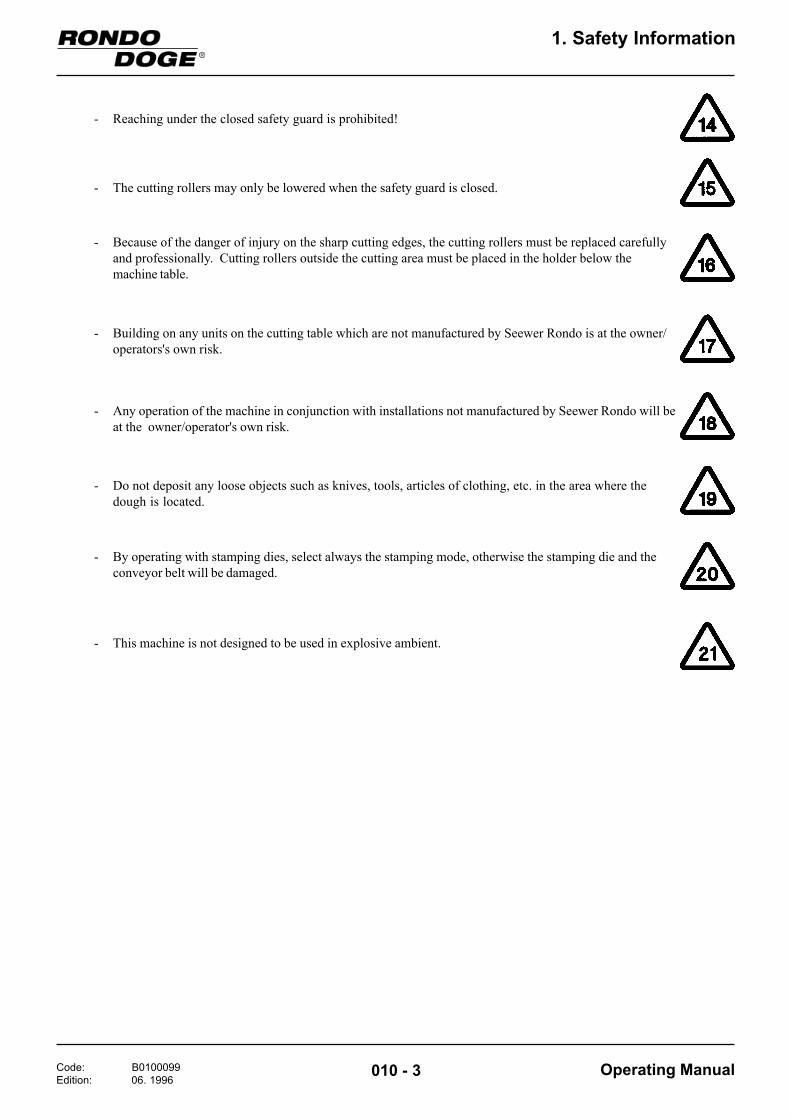
- Reaching under the closed safety guard is prohibited!
- The cutting rollers may only be lowered when the safety guard is closed.
- Because of the danger of injury on the sharp cutting edges, the cutting rollers must be replaced carefullyand professionally. Cutting rollers outside the cutting area must be placed in the holder below themachine table.
- Building on any units on the cutting table which are not manufactured by Seewer Rondo is at the owner/operators's own risk.
- Any operation of the machine in conjunction with installations not manufactured by Seewer Rondo will beat the owner/operator's own risk.
- Do not deposit any loose objects such as knives, tools, articles of clothing, etc. in the area where thedough is located.
- By operating with stamping dies, select always the stamping mode, otherwise the stamping die and theconveyor belt will be damaged.
- This machine is not designed to be used in explosive ambient.

Code: B0200104Edition: 10. 1996
Operating Manual020 - 1
2. Transporting, Setting up, Connecting, Dismounting and Storing
2 Transporting, Setting up, Connecting, Dismounting and Storing the Machine
- Report any claims for damage caused as a result oftransportation directly to the freight handlers (seethe packaging: the delivery documentation isattached to it.
For further information regarding the ambientconditions required for the machine, see GeneralInformation, page 030 - 1
surface.The machine must be set up on a level, even floor
2.2 Transportation
2.3 Unpacking the Machine
The table is supplied with cutting station, drive andbase fully assembled.The filling depositor and control panel are dismountedfrom the table.
2.1 Delivery of the machine
The machine is delivered in its original packaging.
- Check all items received against the delivery slip for completeness
- Unpack the table and accessories.

Code: B0200104Edition: 10. 1996
Operating Manual020 - 2
2. Transporting, Setting up, Connecting, Dismounting and Storing
2.4 Mounting the accessories
2.4.1 Mounting the Guillotine
At least 2 persons are required to set up theguillotine.
For mounting the guillotine proceed as follows:
- Lift the safety guard until the cylinder screw (3)can be firmely secured through the bove into theswitch rod
- By slightly tilting, the safety guards can now beintroduced between the side plates of the guillotine
- Place the safety guard in front of the guillotine insuch a way that the ratched wheel (4) comes to reston the rear side
- Remove the cylinder screws (3) that you find onthe front side of the safety guard rods
For mounting the safety guards proceed as follows:
- Tilt the guillotine carefully and put it up. Hingeimmediately the fixing links (1) on the front andthe rear side by means of tension screws (2)
3
3 1
12
4
Code: B0200104Edition: 10. 1996
Operating Manual020 - 3
2. Transporting, Setting up, Connecting, Dismounting and Storing
9
8
10
11
5
1
7
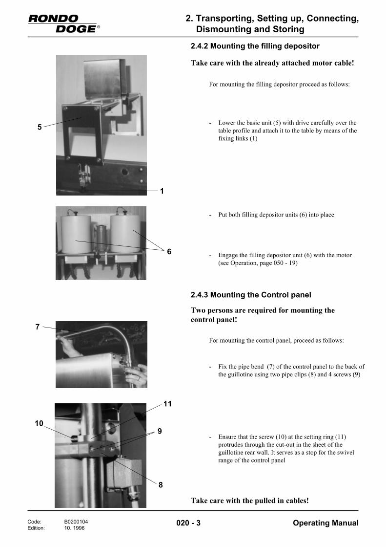
2.4.2 Mounting the filling depositor
Take care with the already attached motor cable!
For mounting the filling depositor proceed as follows:
- Lower the basic unit (5) with drive carefully over thetable profile and attach it to the table by means of thefixing links (1)
- Engage the filling depositor unit (6) with the motor(see Operation, page 050 - 19)
- Put both filling depositor units (6) into place
2.4.3 Mounting the Control panel
Two persons are required for mounting thecontrol panel!
For mounting the control panel, proceed as follows:
- Fix the pipe bend (7) of the control panel to the back ofthe guillotine using two pipe clips (8) and 4 screws (9)
- Ensure that the screw (10) at the setting ring (11)protrudes through the cut-out in the sheet of theguillotine rear wall. It serves as a stop for the swivelrange of the control panel
Take care with the pulled in cables!
6

Code: B0200104Edition: 10. 1996
Operating Manual020 - 4
2. Transporting, Setting up, Connecting, Dismounting and Storing
12
2.5 Requirements for putting the machine into operation
Power supply and frequency at the main circuit to whichthe machine is connected must be in accordance withspecifications contained on a plate affixed to themachine. (This plate is to be found on the electricalcabinet.)
Direct connection without a plug is not permitted!Ensure that the connection is made professionally and inaccordance with local regulations. (A circuit diagram isdelivered with every machine. It is to be found in theelectrical cabinet.)
- Plug the machine into the electrical supply
- It is essential to carry out a moving direction test onthe guillotine (see Guillotine Moving Direction Test,Page 040 - 2)
2.6 Moving the cutting table
- Release the brake (12) on the operating side of thetransport rollers
- Move the cutting table to the desired location
- Re-engage the brake (12)

Code: B0300102Edition: 06. 1996
Operating Manual
3. General Data about the Machine
030 - 1
3 General Data about the Machine3.1 General Information
3.1.1 The Machine's Applications
The hatched area shows the work area designated for theoperating personnel.
3.1.6 Operating Personnel Work Area
Total weight SFT370 = 400 kg
3.1.5 Machine Weight
3.1.4 Ambient Humidity
The ambient temperatures permissible for the machine: + 5° to + 40°CPermissible temperatures for storage of the machine- 25° to + 55 °C, for brief periods up to + 70 °C
Noise emission values at place of operation:"70db(A)" according to DIN 45635
3.1.2 Noise Values
3.1.3 Temperatures
The Rondolino SFT 370 is suitable for cutting, fillingand further processing of dough sheets for the foodindustry.
The ambient humidity permissible for the machine lies inthe area of 30 % - 95 % relative humidity, uncondensed.

Code: B0300102Edition: 06. 1996
Operating Manual
3. General Data about the Machine
030 - 2
3.2 Machine Models
3.2.1 Rondolino SFT 370
being composed of:
- Table with drive- Filling depositor ZFGR- Guillotine ZGM 635 (see Technical Data, Page 090 - 1)
3.3 Prerequisites
In order to be able to process dough sheets on themachine, the following requirements must be met:
Before putting the machine into operation, the beltsmust be lightly rubbed with flour in order to preventthe dough from sticking to the belt.
- Dough weight must not exceed 20 kg
- Dough sheets must be well-flouredThis will serve to prevent the dough from stickingto the cutting rollers and the scraper.
- See also Technical Data, Page 090 - 2

Code: B0300102Edition: 06. 1996
Operating Manual
3. General Data about the Machine
030 - 3
3.4 Full View of the Machine
5 3
11
2 4
10
8
11
13
15 1617
118
6
1 Machine base 2 Shelf 3 Telescopic section 4 Table sheet 5 Conveyor belt 6 Drive unit 7 Supporting bar for baking sheets
(can be pulled out) 8 Reeler support 9 Scraper10 Idle roller11 Cutting station12 Motor13 Cutting roller holding device14 Driving roller15 Guillotine16 Filling depositor17 Control panel18 Electrical cabinet
12
9
7
14

Code: B0400099Edition: 06. 1996
Operating Manual
4. Putting the Machine into Operation
040 - 1
4 Putting the Machine into Operation
- Set the main switch (1) in the electrical cabinet toposition "I"
4.1 Preparing for Operational Readiness
1
2
3 - Close both safety guards (3) of the guillotine
The installation is ready for operation when the orangelamp (5) is no longer illuminated.
5
4
- Close safety guard (2) of the cutting station
- Release emergency-stop key (4)

Code: B0400099Edition: 06. 1996
Operating Manual
4. Putting the Machine into Operation
040 - 2
4.2 Starting / Stopping the machine
- Press ON key (6) (conveyor belt starts up)
In order to start the machine:
- Then repeat the moving direction test
4.3 Guillotine moving direction test
- Press OFF key (7)(conveyor belt stops)
In order to stop the machine:
- Select guillotine using selector switch (8)(turn the switch to the right), counter display (9)illuminates
- Start the machine using the ON key (6)
If no cutting operation takes place:
Whenever the counter display jumps to 00000,the guillotine must carry out a cutting operation.
- Stop the machine using OFF key (7)
- Switch off the machine and reverse 2 phases inthe mains plug
67
8
9
Code: B0400099Edition: 06. 1996
Operating Manual
4. Putting the Machine into Operation
040 - 3
"X" 10
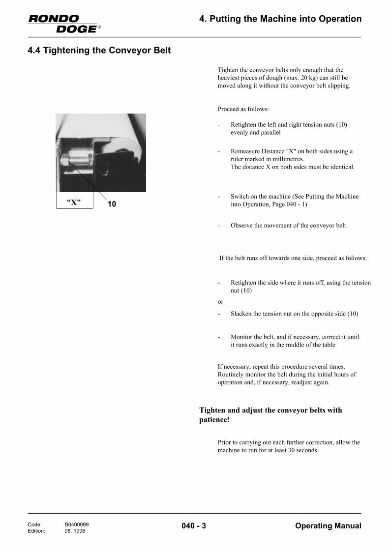
4.4 Tightening the Conveyor Belt
Tighten the conveyor belts only enough that theheaviest pieces of dough (max. 20 kg) can still bemoved along it without the conveyor belt slipping.
Proceed as follows:
- Retighten the left and right tension nuts (10)evenly and parallel
- Remeasure Distance "X" on both sides using aruler marked in millimetres.The distance X on both sides must be identical.
If the belt runs off towards one side, proceed as follows:
- Retighten the side where it runs off, using the tensionnut (10)
- Slacken the tension nut on the opposite side (10)
- Monitor the belt, and if necessary, correct it untilit runs exactly in the middle of the table
If necessary, repeat this procedure several times.Routinely monitor the belt during the initial hours ofoperation and, if necessary, readjust again.
Tighten and adjust the conveyor belts withpatience!
Prior to carrying out each further correction, allow themachine to run for at least 30 seconds.
- Switch on the machine (See Putting the Machineinto Operation, Page 040 - 1)
- Observe the movement of the conveyor belt
or

Code: B0500119Edition: 10. 1996
Operating Manual
5. Operation
050 - 1
5 Operation5.1 Control panel, operation
Counter, filling depositor
Conveyor belt
5.1.1 Conveyor belt
The Rondolino together with the active accessories areswitched on by operating the green ON key.
The Rondolino together with the active accessories areswitched off by operating the red OFF key.
The conveyor belt speed is adjusted by means of thepotentiometer.
- Stage 1 - minimum belt speed = 0.8 m/min- Stage 10 - maximum belt speed = 7.0 m/min
101
Operation of the Emergency Stop key in the event of anemergency stops the entire installation immediately. TheEmergency Stop circuit is released by turning theEmergency Stop key in the direction of the arrow.
If the safety circuit is interrupted due to an open safetyguard or the Emergency Stop key, the orange lampilluminates.
Guillotine

Code: B0500119Edition: 10. 1996
Operating Manual
5. Operation
050 - 2
5.1.2 Guillotine
Cutting and stamping movementsrespectively are initiated by the presetcounter.
The guillotine drive is switched on and offtogether with the conveyor belt.
III In the left position (I) the guillotine and preset counterare switched off.
In the right position (II) the guillotine and the presetcounter are switched on.
When working with the stamping tool, the selector switchhas to be set to the left position (I, Stamping mode).The conveyor belt stops whilst the guillotine performs acutting operation.
When working with the cutting tool, the selectorswitch has to be set to the central position (II, Cuttingmode). The conveyor belt is not stopped whilst theguillotine performs a cutting operation.
If the selector switch is briefly turned to the right(position III) the clutch of the swing arm is disengaged..This permits the cutting or stamping tool respectively tobe lowered manually. (see also Lowering the guillotine inorder to change the tools, Page 050 - 13)
IIII II
Guillotine ON/OFF selector switch
Selector switch for Stamping / Cutting /Manual
Please note:Only disengage the clutch when the machine is notin operation. The installation must however beready for operation. (safety guards closed, orangelamp must not be illuminated)

Code: B0500119Edition: 10. 1996
Operating Manual
5. Operation
050 - 3
The product length, i.e. the cutting length of theguillotine and the dispensing distance of the fillingdepositor is entered on the preset counter (values in mm).
The preset counter is only switched on when theguillotine is switched on.
- Operate one of the black keys on the counter.The preset is now displayed on the counter
- A key is allocated to each digit of the display. Pressthe corresponding key in order to amend thepresent.
Four seconds after the last operation of a key thecounter setting is automatically displayed once againand the counter is ready for operation.
The red reset key resets the currently displayedcounter setting to zero.
Setting the product length (preset)
The correct positioning of the cut to the filling takesplace by moving the guillotine.
The cut initiation of the guillotine and the start-up ofthe filling depositor take place simultaneously (presetcounter)
Cutting adjustment
To move the guillotine proceed as follows:
- Slacken locking screws (8) front and rear by approx.2 - 3 turns.
- Retighten the locking screws at the front and rear.
- Turning the two star grips (29) allows the entireguillotine to be moved to precisely the rightposition
82929

Code: B0500119Edition: 10. 1996
Operating Manual
5. Operation
050 - 4
5.1.3 Filling depositor
The filling depositor is made ready foroperation when the conveyor belt isswitched on.
The switching command for filling takesplace by means of the preset counter.
1 10
- The filling depositor is switched off when the selector switch is placed in the upright position (II) .
- By turning the selector switch to the left (position I) the filling depositor is set to automatic operation.
III III
Selector switch AUTO - O - Manual
1 10
- This potentiometer is used to set the application time (running time) of the filling depositor (for intermittent filling only).
- Stage 1 = approx. 0.5 sec. filling duration- Stage 10 = approx. 4 sec. filling duration
- By turning the selector switch to the right (position III) the filling depositor will run for as long as the selector switch is operated.
- This potentiometer is used to set the speed with which the filling is to be applied.

Code: B0500119Edition: 10. 1996
Operating Manual
5. Operation
050 - 5
Selector switch for operating mode
- With the selector switch in the upright position (II) the filling depositor operates discontinuously without stopping the conveyor belt.
- With the selector switch in the right-hand position (III), the filling depositor operates discontinuously but stops the conveyor belt during the filling process.
- With the selector switch in the left-hand position (I) the filling depositor operates continuously.
III III

Code: B0500119Edition: 10. 1996
Operating Manual
5. Operation
050 - 6
5.2 Standard Cutting Device
1
2
23 3
4
The cutting table comes equipped with a cuttingdevice.
5.2.1 Cutting Device
1 Cutting rollers2 Tension lever3 Stop lever
Safety guard
The cutting device is covered by a safety guard (4).

Code: B0500119Edition: 10. 1996
Operating Manual
5. Operation
050 - 7
5.2.2 Types of Cutting Rollers
Docking roller
Length cutter
Cross cutter
Zigzag cutter
Form cutting roller
Tandem cutter
W H Number of rows
120140180*180
105180140100
5345
H
W
Some standard dimensions for zigzag cutters in stainlesssteel for triangles.
* Also available in plastic

Code: B0500119Edition: 10. 1996
Operating Manual
5. Operation
050 - 8
5.2.3 Insert Cutting Rollers
56
1
The cutting rollers (1) must be inserted in the runningdirection of the dough in the following sequence:
a) For Squares /Rectangles
First cut lengthwise, then crosswise
In order to ensure smooth operation of the crosscutter, the cutter must be inserted in the cuttingdirection in such a manner that the dough sheet is firstcut with the cutting knife (5) and then ejected by theejector (6).
b) For Triangles:
First use zigzag, then length cutter
Danger of injury on the sharp cutting edges of thecutting rollers!
- Raise the safety guard (4) on the cutting device
Cutting rollers not being used must be stored inthe rest provided for this purpose.Reason: This will prevent damage to the cuttingknives.Injury to the operator will also be prevented.

Code: B0500119Edition: 10. 1996
Operating Manual
5. Operation
050 - 9
2
2 33
11
5.2.5 Lifting Cutting Rollers
- Gently push the tension lever (2) downwards
- Release the tension lever (2) and lift to the limitstop
- Turn the stop lever (3) clockwise to the limit stop
4
11
2
3
- Close safety guard (4)
- Lift tension lever (2) gently and turn the stop lever (3)in a counter-clockwise direction to the limit stop
- Lower tension lever (2) until the cutting roller (1) islaying on the belt
The further down the tension lever (2) is lowered, thegreater the cutting pressure.
5.2.4 Lowering Cutting Rollers
23
Do not set so great a cutting pressure thatdamage is caused to the conveyor belt!
When using a length cutter, make sure to watchout for the following:As soon as the length cutter is touching the belt,lower the tension lever by only 2 steps further atthe most, otherwise the belt could be cut.

Code: B0500119Edition: 10. 1996
Operating Manual
5. Operation
050 - 10
5.2.6 Cutting
The width of the dough sheet must correspond to thelength of the cutting roller to be used plus approx.1 - 2 cm on both sides.
Fault finding Cause/Defect Remedy/to remove1. Dough piece sticks on cutting roller. Dough too moist. Flour dough piece well.
5.2.7 Sources of Errors in the Cutting Operation

Code: B0500119Edition: 10. 1996
Operating Manual
5. Operation
050 - 11
Eccentric
Motor
Toothed belt
Wrap spring clutch/Shaft
Guide
Knife
Dough
7
9
10
8
12
5.3 Guillotine
5.3.1 Full View of the Guillotine
5.3.2 Function principle
13
11
9
Legend 7 Cutting tool 8 Locking screw 9 Setting screws10 Safety guard11 Retaining screw12 Safety guard hook13 Adjusting screw
Swing arm

Code: B0500119Edition: 10. 1996
Operating Manual
5. Operation
050 - 12
5.3.3 The guillotine's applications
The guillotine is suitable for cross-cutting andstamping of dough products with or without fillling.
The guillotine is only to be operated together with themachine supplied by RONDO.
- Observe the technical data for the guillotine (seeTechnical Data, Page 090 - 2)
- for cutting 70 lifting operations/min. - for stamping 50 lifting operations/min.
- Maximum product height = 35 mm (Safety guard opening)
The no. of lifting operations is determined by theproduct length and the conveyor belt speed.
5.3.4 Engaging/Disengaging the safety guard
Opening
- Open the safety guard sufficiently until the hookengage by themselves
- Using one hand, lift the safety guard a little, usingthe second hand to lift the hook so that the safetyguard can be lowered
Closing
Please note:
- Maximum product length for stamping = 150 mm
- Maximum permitted no. of lifting operations for the guillotine:

Code: B0500119Edition: 10. 1996
Operating Manual
5. Operation
050 - 13
5.3.5 Lowering the guillotine in order tochange the tools
- Close the safety guardThe installation must be ready for operation, theorange lamp on the control panel may not beilluminated (see Conveyor Belt, Page 050 - 1)
- Release the clutch of the swing arm (see selectorswitch stamping / cutting / manual, Page 050 - 2)
- Lower the guillotine until the tool rests on theconveyor belt (see Lowering the guillotine in orderto change the tools, Page 050 - 13)
- Completely slacken the retaining screw (11) of thescraper. Pull the hold-down device forward and rest iton the conveyor belt (only in the case of the cross-cutting knife) (see also Mount hold-down devicewith scraper, Page 050 - 15)
5.3.7 Mounting the cross-cutting knife or stamping die
- Lower the guillotine (see Lowering the guillotine inorder to change the tools, Page 050 - 13) Ensurethat the swing arm is moved slightly beyond thelower dead point, i.e. lower the swing arm until itmoves slightly upwards again
- Mount the hold-down device (see Mounting thehold-down device with scraper, Page 050 - 15)
8
14 14
- Remove the stamping die or cross-cutting kniferespectively together with the hold-down device
- Completely unscrew locking screw (8)
- Using the socket head wrench, turn the swing armof the guillotine over the dead point until the toolhas lifted off the conveyor belt
- Slacken locking screw (8)
- Insert the cross-cutting knife together with the hold-down device or the stamping die respectively over theretaining bolts (14). Mounting takes place on the inputside of the guillotine
- Mount the locking screw (8) and tighten securely
5.3.6 Removing the cross-cutting knife orstamping die
- Using the socket head wrench, lower the swing armof the guillotine until the tool rests on theconveyor belt. Turn in a clockwise direction!
- Open the safety guard

Code: B0500119Edition: 10. 1996
Operating Manual
5. Operation
050 - 14
5.3.8 Adjusting the height of the cross-cutting knife and the stamping die
- Move the knife or stamping die respectively to thelowest position (dead point) (see Lowering theguillotine in order to change the tools, Page 050 - 13)
- Fully slacken the lower (15) and upper nuts (16) of theholder (17) (output side of the guillotine)
- Tighten the upper left and right nuts (16) equallyuntil the knife or the stamping die respectively lieacross the full width of the conveyor belt
- Check:By turning the socket head wrench (in clockwisedirection) move the knife or stamping dierespectively to the uppermost position and back. Itmust be possible to move the knife or stamping dierespectively through the lowest position.
If this is no longer possible there is a risk of damageto the conveyor belt.
- Tighten the two lower nuts (15) firmly
17
1516
- Gently tighten lower nuts (15)
The height adjustment is only necessary when firstmounting the cross-cutting knife or stamping dierespectively, or if the dough is not completely cut.

Code: B0500119Edition: 10. 1996
Operating Manual
5. Operation
050 - 15
5.3.9 Mount the hold-down device(with scraper)
Conveyor belt
Profile oftable
11
18
19
20
21
- Adjust the height of the hold-down device sheets (21)such that these have a distance of approx. 5 mm fromthe product
- Lift the hold-down device at the front and screw theholding screw (11) into the hole. Firmly tighten theholding screw and then secure with the counter nut (20)The counter nut will prevent the hold-down devicefrom working loose during operation
Adjust the hold-down device sheets as follows:
- Lay hold-down device sideways, move alongunder the knife and raise
The front side with the two pins (18) is mountedtowards the rear.
- Lift the cross-cutting knife by hand with sockethead wrench
Mount the hold-down device as follows:
- Move the two pins (18), on the back of the hold-down device, into the two centring holes in theretaining plate (19)

Code: B0500119Edition: 10. 1996
Operating Manual
5. Operation
050 - 16
5.3.10 Mount and dismount the scraper
21 21
23 23
22 22
Knife- Hook tension springs of the scrapers on the side
- Insert scraper into the lateral guides and pressdown as far as possible
- Slide the hold-down sheet downwards as far aspossible
To mount proceed as follows:
- Lift out the scraper
- Unhook the tension springs (22) of the scraper (23)
- Slide the hold-down sheet (21) downwards as far aspossible
To dismount proceed as follows:

Code: B0500119Edition: 10. 1996
Operating Manual
5. Operation
050 - 17
5.4 Filling depositor
Filling
Pump Impeller
5.4.1 Full View of the Filling depositor (4-rows)
24
25
262627
28
24
Legend24 Filling depositor unit25 Basic unit with drive26 Cover27 Motor28 Locking screw
5.4.2 Function principle
Container
Nozzle

Code: B0500119Edition: 10. 1996
Operating Manual
5. Operation
050 - 18
5.4.3 The filling depositor's applications
This filling depositor can be used to process freelyflowing and stiffer fillings, also to some extent thosecontaining small solid contents.
Abrasive and very coarse filling materials, whichcontain for example undissolved sugar crystals candamage any parts which come into contact with thefilling material!
- Freely flowing filling materials for which no cover is necessary can be continuously topped up (without stopping production).
- Fillings may not exceed a temperature of maximally 40°C
- This filling depositor permits continuous or discontinuous application of the fillings.
- Observe the technical data for the filling depositor(see Page 090 - 2)
- If a single filling row only is required, both nozzles are used in combination so that only a single row is produced. The motor with the filling unit can be moved to the side after releasing the locking screw.
Please note:
- If three filling rows are required, the impeller of one filling depositor is removed. (Shaft rest mounted!) When using fluid fillings, the opening has to be closed by enclosed reducer and sealing cap.

Code: B0500119Edition: 10. 1996
Operating Manual
5. Operation
050 - 19
5.4.4 Operation
WarningNever allow the filling depositor to run dry! (wearand tear)
- Mount the container.Safety notice on the container on the output side of thefilling depositor (side of guillotine)
In order to connect the filling depositor unit to themotor, proceed as follows:
- Set minimum speed for the filling depositor on thepotentiometer (see selector switch AUTO - O -Manual, Page 050 - 4)
- Keep selector switch "AUTO - O - Manual" inposition "Manual" (see selector switch "AUTO - O -Manual", Page 050 - 4)
- At the same time, press the filling depositor unitagainst the motor until the shaft engages in thecatch sleeve.
- Fill the filling into the container
- In order to obtain an accurately weighedapplication, care must be taken that the (non free-flowing) filling is homogeneously filling, that is tosay there are no trapped air bubbles.
- For highly viscous fillings, it is recommended touse a cover and press it firmly on the filling.
- Adjust the nozzles according to the product
- In order to be able to refill the container, the covermust be removed or ventilated by pulling out theblue plug.
- Set the required operating mode on the controlpanel (see Selector switch for operating mode,Page 050 - 5)
Code: B0600099Edition: 06. 1996
Operating Manual
6. Cleaning
060 - 1
6 Cleaning6.1 Cleaning the table
6.1.1 General Information
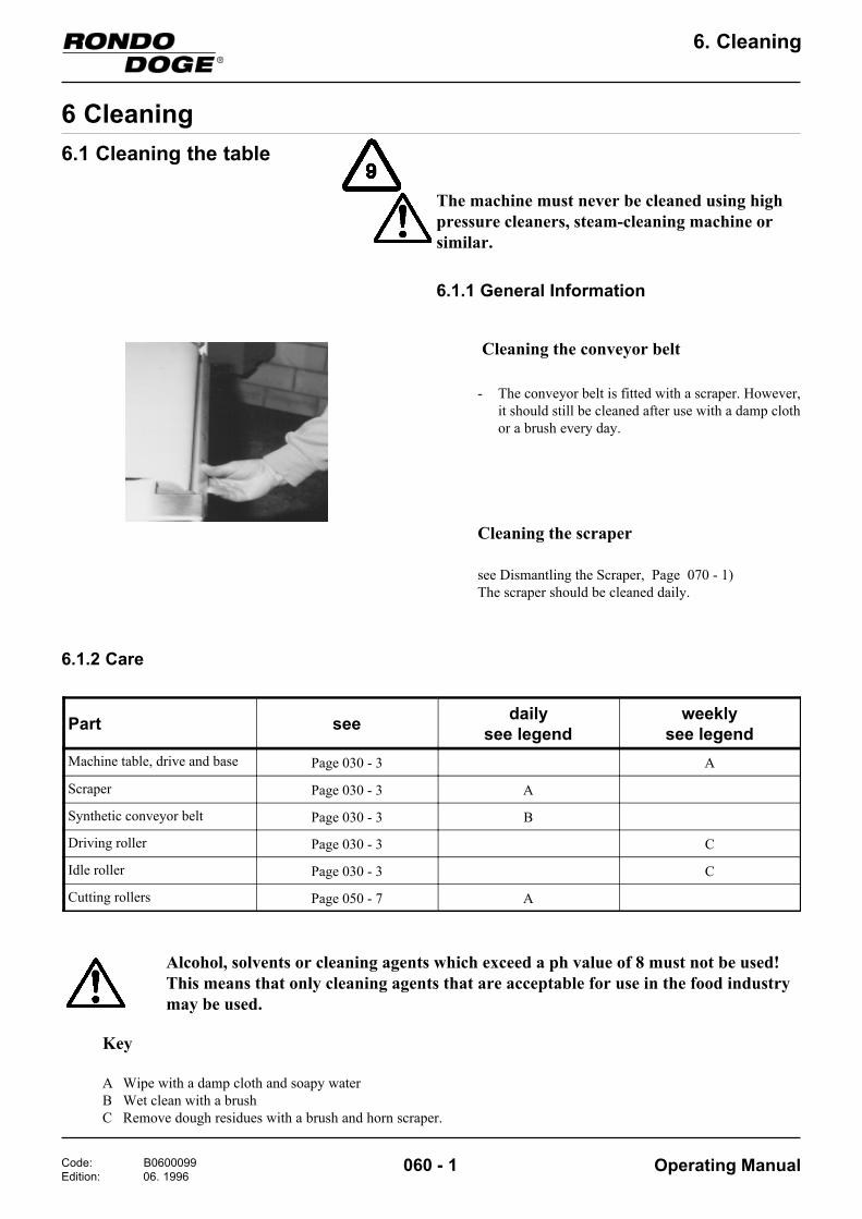
Cleaning the conveyor belt
Part see dailysee legend
weeklysee legend
Machine table, drive and base Page 030 - 3 A
Scraper Page 030 - 3 A
Synthetic conveyor belt Page 030 - 3 B
Driving roller Page 030 - 3 C
Idle roller Page 030 - 3 C
Cutting rollers Page 050 - 7 A
The machine must never be cleaned using highpressure cleaners, steam-cleaning machine orsimilar.
Cleaning the scraper
see Dismantling the Scraper, Page 070 - 1)The scraper should be cleaned daily.
Key
A Wipe with a damp cloth and soapy waterB Wet clean with a brushC Remove dough residues with a brush and horn scraper.
6.1.2 Care
Alcohol, solvents or cleaning agents which exceed a ph value of 8 must not be used!This means that only cleaning agents that are acceptable for use in the food industrymay be used.
- The conveyor belt is fitted with a scraper. However,it should still be cleaned after use with a damp clothor a brush every day.
Code: B0600099Edition: 06. 1996
Operating Manual
6. Cleaning
060 - 2
6.2 Cleaning the guillotine
The cross-cutting knife, scraper and stamping toolsshould be cleaned daily.They may be cleaned using water.
The guillotine should be cleaned at least once a weekusing a cloth and soapy water.
6.2.1 Care
Alcohol, solvents or cleaning agents whichexceed a ph value of 8 must not be used! Thismeans that only cleaning agents that areacceptable for use in the food industry may beused.
The guillotine must never be cleaned using highpressure cleaners, steam-cleaning machine orsimilar.
Code: B0600099Edition: 06. 1996
Operating Manual
6. Cleaning
060 - 3
6.3 Cleaning the filling depositor
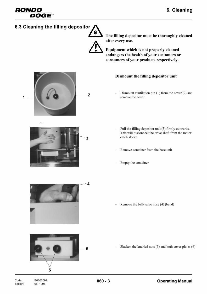
Dismount the filling depositor unit
Equipment which is not properly cleanedendangers the health of your customers orconsumers of your products respectively.
The filling depositor must be thoroughly cleanedafter every use.
1
3
- Empty the container
- Remove container from the base unit
- Pull the filling depositor unit (3) firmly outwards.This will disconnect the drive shaft from the motorcatch sleeve
4
5
- Slacken the knurled nuts (5) and both cover plates (6)
- Remove the ball-valve hose (4) (bend)
6
2 - Dismount ventilation pin (1) from the cover (2) andremove the cover
Code: B0600099Edition: 06. 1996
Operating Manual
6. Cleaning
060 - 4
7
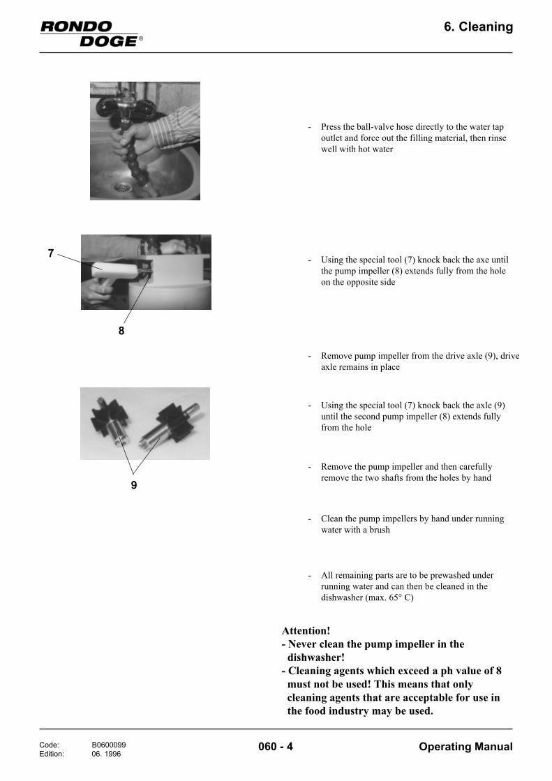
- Press the ball-valve hose directly to the water tapoutlet and force out the filling material, then rinsewell with hot water
- Using the special tool (7) knock back the axe untilthe pump impeller (8) extends fully from the holeon the opposite side
8
- Remove pump impeller from the drive axle (9), driveaxle remains in place
9
- Using the special tool (7) knock back the axle (9)until the second pump impeller (8) extends fullyfrom the hole
- Remove the pump impeller and then carefullyremove the two shafts from the holes by hand
- Clean the pump impellers by hand under runningwater with a brush
- All remaining parts are to be prewashed underrunning water and can then be cleaned in thedishwasher (max. 65° C)
Attention!- Never clean the pump impeller in the dishwasher!- Cleaning agents which exceed a ph value of 8 must not be used! This means that only cleaning agents that are acceptable for use in the food industry may be used.

Code: B0600099Edition: 06. 1996
Operating Manual
6. Cleaning
060 - 5
Mount the filling depositor unit
1011
7
8
- Push the pump impeller to the drive axle
Attention:A filling depositor unit always consists of a shaft (9)with a pin (10) and a shaft with a hole (11).
- Place the special tool (7) on the pump impeller (8)and turn into the hole using a vigorous turningmovement
The filling container is then ready for use.
- Mount the two ball-valve hoses
- At the other side proceed in the same way
- Remount the cover plate (6) and secure the knurlednuts (5)
Code: B0700116Edition: 10. 1996
Operating Manual
7. Maintenance
070 - 1
7 Maintenance7.1 General Information about Table Maintenance
Any defects on the machine must be repaired byan authorized customer service!
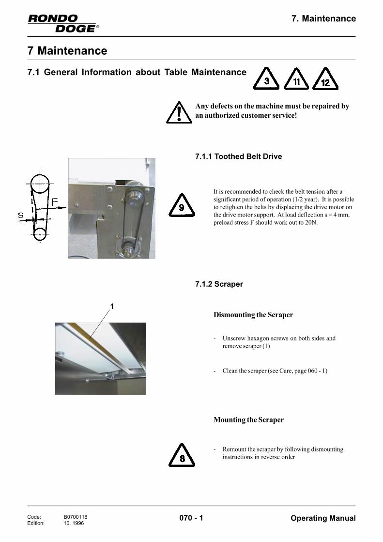
7.1.1 Toothed Belt Drive
It is recommended to check the belt tension after asignificant period of operation (1/2 year). It is possibleto retighten the belts by displacing the drive motor onthe drive motor support. At load deflection s = 4 mm,preload stress F should work out to 20N.
1
7.1.2 Scraper
Dismounting the Scraper
- Unscrew hexagon screws on both sides andremove scraper (1)
- Clean the scraper (see Care, page 060 - 1)
Mounting the Scraper
- Remount the scraper by following dismountinginstructions in reverse order

Code: B0700116Edition: 10. 1996
Operating Manual
7. Maintenance
070 - 2
7.1.3 Maintenance List
The use of conveyor belts not supplied by Rondocan lead to premature wear on or destruction ofmachine parts (scraper, drive rollers, etc.)
7.1.4 Replacement Parts List
.onmetI noitpircseD snoisnemiD noitacilppA
83501 wolsesuF A51,3T tenibaclacirtcelE
23411 gnitcakciuqrepusesuF mm02x5,A3,6FF tenibaclacirtcelE
898301 reparcS 1-070egaP
30T898301 reparcS 1-070egaP
315601 tlebroyevnoC)tlebroyevnoccitehtnyS(
mm046x0127 5.soP,3-030egaP
27305 tleBdehtooT 51-006-RM5TG 1-070egaP
KeyW weeklyM monthly1/2 J semi-annuallyJ annually
traP/tahW ytivitcA gnikrowyliadnahtsselemit
h4
gnikrowyliadh8-4emit
gnikrowyliaderomemit
h8naht
stleBroyevnoC kcehcecalper:yrassecenfi
M W W
reparcS elbissoprofkcehcotehtdnasegamad
ecroferusserp
J2/1 M M
tleBdehtooT kcehcetaluger:yrassecenfiecalperronoisneteht
J J2/1 J2/1

Code: B0700116Edition: 10. 1996
Operating Manual
7. Maintenance
070 - 3
7.2.2 Replacement Parts List
The guillotine does not need any maintenance.
Item no. Description124029T01 Scraper
50406 Toothed Belt GT 5MR-510-20
Any defects or damage on the Guillotine must berepaired by an authorized customer service!
7.2.1 Maintenance
7.2 General Information for Maintenance of the Guillotine

Code: B0700116Edition: 10. 1996
Operating Manual
7. Maintenance
070 - 4
7.3 General Information for Maintenance of the Filling depositor
Any defects or damage on the Filling depositormust be repaired by an authorized customerservice!
7.3.1 Maintenance
.onmetI noitpircseD
088621 rellepmipmuP
56405 21/8gniR-O
87105 05/44gniR-O
98453 etelpmocrevoC
190421 reniatnoC
918631 xonIreniatnoC
531421 lootlaicepS
85405 "4/3gnilpuoC
95405 "4/3kniL
16405 mm61,"4/3elzzoN
06405 mm21/91noitcudeR
36405 mm5,9,"2/1elzzoN
26405 mm5,21,"2/1elzzoN
09405 pacgnilaeS
The filling depositor does not need any maintenance.
7.3.2 Replacement Parts List

Code: B0800099Edition: 06. 1996
Operating Manual
8. Trouble shooting
080 - 1
8 Trouble shooting
Symptom Cause/Defect Remedy/To remove
1. Once the machine has been assembled, nothing works.
- Mains plug not plugged in or incorrectly plugged in.- Safety guard not lowered.- Emergency Stop not unlocked
Plug in mains plug (correctly).
Lower safety guard.Unlock the Emergency Stop
2. Machine shuts itself off. - Maladjusted safety guard limit switch.
- Loose cables, wires.
Have it adjusted by a "Rondo" CustomerService Center.Let check it by an electrician.Secure cables and wires properly.
3. Drive motor runs, conveyor belt does not move.
Toothed belt loose or defective. Remove the cover of the drive, retightentoothed belt and, if necessary, replace(See Toothed belt drive, Page 070 - 1)
4. Conveyor belt slips, drive motor and driving rollers turn.
- Insufficient conveyor belt tension.
- Dirty driving roller.
Retighten conveyor belt evenly (SeeTightening the Conveyor belt,Page 040 - 3)Clean driving roller (See Care,Page 060 - 1)
5. Conveyor belt runs off the side, becomes worn at the edges.
- Conveyor belt tension incorrectly set.
- Dirty driving roller.
Tighten conveyor belt (See Tighteningthe Conveyor belt, Page 040 - 3)Clean driving roller (See Care, Page 060 - 1)
6. Conveyor belt does not move at all or the desired speed cannot be set using potentiometer.
- Defective speed regulator or potentiometer.- Fuse of speed regulator defective
Call upon the services of qualifiedpersonnel (electrician).
7. Guillotine stands still. - Electrical links are not/not correct connected.- Safety guard of the guillotine or of the cutting station is not closed.- Selector switch "Guillotine" on the control panel is not switched on (is in position "0").
Connect correctly the links. (Guillotineplug)Close the safety guard.
Switch on the selecetor switch"Guillotine" on the control panel (seealso Guillotine, Page 050 - 2).
8. Motor of the Guillotine runs, but no cutting movement take place.
Moving direction of the Motor iswrong.
Moving direction test (See GuillotineMoving direction test, Page 040 - 2)
9. Dough sheet is not/not sufficiently cut resp. stamped.
Cross-Cutting knife or Stamping toolsare not mounted or adjusted correctly.
Mount resp. adjust correctly theCross-Cutting knife resp. Stamping tools(see also Adjusting the height of theCross-Cutting knife and the Stampingdie, Page 050 - 14)

Code: B0800099Edition: 06. 1996
Operating Manual
8. Trouble shooting
080 - 2
Symptom Cause/Defect Remedy/To remove
10. Filling depositor is not conveying. - Safety guard of the guillotine or the cutting station is not closed.- Selector switch "Filling depositor" on the control panel is not switched on. (is in position "0")
- Filling depositor unit is not connected to the motor.
- Pump impeller defective.
- Pump impeller not/not correct mounted.
- Pump system leaky.
- Viscous mass.
Close the safety guard.
Switch on the selector switch "Fillingdepositor" on the control panel (inposition "Auto") (See Filling depositor,Page 050 - 4).Press the Filling depositor unit to thecatch sleeve of the motor. (SeeOperation, Page 050 - 19)Replace the pump impeller (SeeCleaning Filling depositor, Page 060 - 4)Mount (correctly) the pump impeller(See Cleaning Filling depositor, Page060 - 4)Replace defective O-rings, Close theCover with knurled screw. (SeeReplacement parts list, Page 070 - 4)Put in the cover
11. All other faults / falling outs. Contact the next "SEEWER RONDO"After-sales-service with giving them somuch informations as possible.

Code: B0900102Edition: 06. 1996
Operating Manual
9. Technical Data
090 - 1
9 Technical Data
9.1 Technical Data Rondolino
ataDlacinhceT 073TFS
htdiwelbaT mm517
htdiwtlebroyevnoC mm046
latotthgnelelbaT mm0553
thgieH mm219
tlebroyevnocfodeepS nim/m0,7-8,0
rewopdetaR seriosseccaevisulcniAVk5,1
egatlovylppuS ,V024-002x3zH06/05
egatlovlortnoC CDV42
htdiwenihcam.xaM mm029
)reward.lcni(htgnellatoT mm0714
:seriosseccaevisulcni073TFSthgiewenihcaM gk004

Code: B0900102Edition: 06. 1996
Operating Manual
9. Technical Data
090 - 2
9.2 Technical Data GuillotineataDlacinhceT 536MGZ
htgnellatoT mm076
htdiwlatoT mm008
)elbatmorf(thgiehlatoT mm526
draugytefasdenepohtiwthgieH mm576
draugytefasfoegassaP mm53
egatlovlortnoC )CAV011(CDV42
evirD rotomraeg-CA
gnittuC)a
efinkgnittuc-ssorcfohtdiW mm016
htdiwelbasU mm006
laminimhtgnelgnittuC mm01
lamixamnoitareposuonitnocnisekortsfooN nim/107
gnipmatS)b
lamixamhtgnelgnipmatS mm051
htdiwgnipmatS mm085
srotcejehtiwseidybsekortsfooN nim/105
lamixamssenkcihthguoD mm51
9.3 Technical Data Filling depositorataDlacinhceT RGFZ
yticapacreppoH l21
sgnillifelbissimdA )stnetnocdilosllamshtiw(sgnillifgniwolfeerf-)stnetnocdilosllamshtiw(sgnillifreffits-
gnissecorpyberutarepmeT C°04llit
gninoitcnuF suounitnoc-potstlebtuohtiwsuounitnocsid-
potstlebhtiwsuounitnocsid-
steltuoforebmuN tinurotisopedgnillifreve2
ytitnauqnoitacilppA teltuorevemc01/g001-01.xorppa,suounitnoc-tops/g06-3.xorppa,potstlebhtiwsuounitnocsid-
evirD rotomraeg-CD
Technical specifications subject to change without notice

Code: B0900102Edition: 06. 1996
Operating Manual
9. Technical Data
090 - 3
9.4 Additional informationFor the Rondo-Doge Rondolino we use the following materials, which are approved for coming into contact withfood stuff:
- The conveyor belts made of plastic material:All plastic coated conveyor belts used on ourmachines correspond with the requirements of theFDA (Food and Drug Administration, USA).
- The parts of the cutting knives that are touchingthe dough are made of stainless steel (chromiumnickel steel, DIN Mat. no. 1.4301, 1.4016).
- The roller of the manual dough reeler that istouching the dough is made of aluminium,anodised colourless.
- The scrapers of the scrap deflectors are made ofstainless spring steel (DIN Mat. no. 1.4310) and areadditionally Teflon-coated.
The scraper blade of the conveyor belt scraper ismade of plastic material (POM-C). This materialcorresponds with the requirements of the "Bundes-gesundheitsamt BGA", Germany).
- Guillotine ZGM635:The knives and the hold-down device sheets aremade of stainless steel (chromium nickel steel,DIN Mat. no. 1.4301, 1.4016).The scrapers blade are made of plastic material(POM-C). This material corresponds with therequirements of the “BundesgesundheitsamtBGA”, Germany.
- Filling depositor ZFGR:The containers are made of PP (polypropylene).The pump impellers are made of XNBR (specialnitrile rubber)The ball-valve hoses incl. outlet nozzle are made ofPOM (polyoxymethylene)
- Not explicit mentioned parts with dough contact:
- Parts made of steel, sheet steel: Material chromium nickel stainless steel (DIN Mat. no. 1.4301, 1.4016, 1.4104 or 1.4305)
- Parts made of aluminium: Aluminium surface treated (anodised colourless or have an anodised layer in which Teflon is settled)
- Parts made of plastic material: POM-C (polyoxymethylene) PETP (polyethyleneterephthalate) PA (polyamid) PE-UHMW (polyethylene, ultrahigh molecular) PP (polypropylene)
The parts of the accessories which come into contactwith dough are indicated in the operating manual ofthe corresponding accessory.