operating mojo - rick wagnerrjwagner49.com/art/mojo/operatingmojorev20090501.pdf · operating mojo...
TRANSCRIPT
Operating Mojo06/06/2007
Start............................................................................................................................................ ..2Operating Mojo.................................................................................................................... ....... ..3Administration............................................................................................................................. ..5
KUKA PC ............................................................................................................. ....... ....... .....5KUKA control cabinet................................................................................................. ....... .......5KUKA system configuration...................................................................................................... 6Vision system PC............................................................................................................. ....... .7Router D-Link WBR-1310................................................................................ ....... ....... ....... ...8Internet connection line................................................................................................ ....... ...10
Configuration files......................................................................................................... ....... .......11Code................................................................................................................................ ....... ....11Error messages.......................................................................................................... ....... ....... ..16

Start
Robot
Start up procedure from scratch:
#1) Press the E-Stop button#2) Check if key switch is in position "Auto"#3) Turn on robot, wait for robot to be up and running#4) Release E-Stop button
Start up procedure after a error message which caused the robot to stop:
#1) Press the E-Stop button#2) Switch key to position “T1”#3) Acknowledge error messages#4) Switch key to position “Auto”#5) Release E-Stop button
Vision System Computer
The vision system computer is running a program named MojoStarter. It will be started automatically at startup. There is an alias on the desktop to start the program manually.
Operating Mojo
The vision system recognizes movements in both camera views and sends the according coordinates over a serial RS232 cable to the robot controller. It is running constantly and is sending even data when the robot is not in action.
Every 10 seconds the system is updating a micro website containing– a screenshot of the robot's control panel– camera 1 +2 views masked to reflect the vision systems area of interestWebsite access: http://216.193.204.20:88/mojo
The robot knows six states of action:GO_TRACKINGTRACKINGGO_ANIMATINGANIMATINGGO_SLEEPINGSLEEPING
The robot starts in the morning and changes from SLEEPING to GO_TRACKING and reaches TRACKING. If there is no data from the vision system for a certain time (approx. 20-30 seconds), he changes to GO_ANIMATING and ANIMATING. When there is activity noticed (data from the vision system) he changes to GO_TRACKING and TRACKING. Please note that the robot has to finish his actual animation move to realize the change in action.If it is time to turn on the light, it will be switched on, no matter in which state the robot is.if there is time to end the performance the robot changes to GO_SLEEPING and SLEEPING.
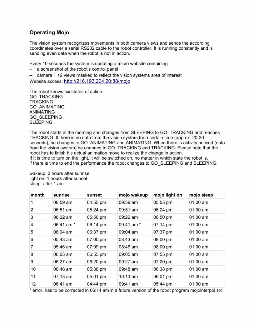
wakeup: 3 hours after sunriselight on: 1 hours after sunsetsleep: after 1 am
month sunrise sunset mojo wakeup mojo light on mojo sleep1 06:59 am 04:55 pm 09:59 am 05:55 pm 01:00 am2 06:51 am 05:24 pm 09:51 am 06:24 pm 01:00 am3 06:22 am 05:50 pm 09:22 am 06:50 pm 01:00 am4 06:41 am * 06:14 pm 09:41 am * 07:14 pm 01:00 am5 06:04 am 06:37 pm 09:04 am 07:37 pm 01:00 am6 05:43 am 07:00 pm 08:43 am 08:00 pm 01:00 am7 05:46 am 07:09 pm 08:46 am 08:09 pm 01:00 am8 06:05 am 06:55 pm 09:05 am 07:55 pm 01:00 am9 06:27 am 06:20 pm 09:27 am 07:20 pm 01:00 am10 06:48 am 05:38 pm 09:48 am 06:38 pm 01:00 am11 07:13 am 05:01 pm 10:13 am 06:01 pm 01:00 am12 06:41 am 04:44 pm 09:41 am 05:44 pm 01:00 am* error, has to be corrected in 06:14 am in a future version of the robot program mojointerpol.src
As the KUKA internal clock does not change with daylight saving this schedule has to be interpreted with the time as of june, 2nd when we put mojo in operation.
Daylight saving information:Clocks were set ahead one hour on the second Sunday of March (March 11, 2007). Clocks will be set back one hour on the first Sunday in November (November 4, 2007).
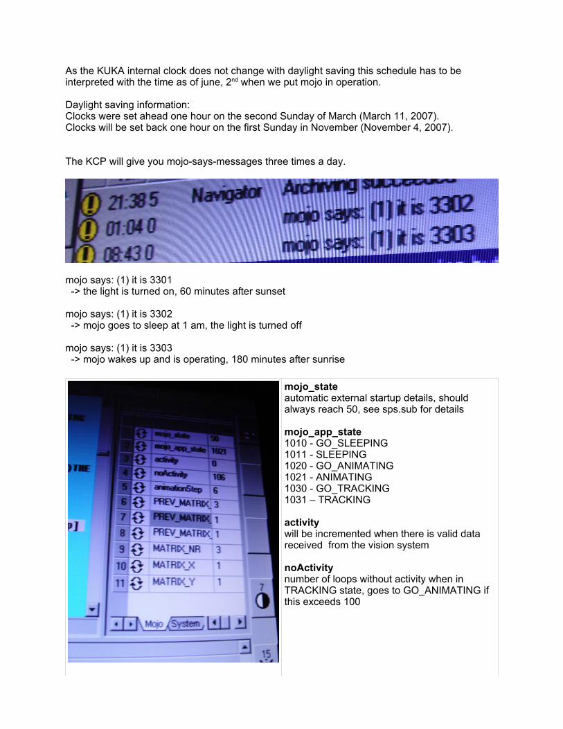
The KCP will give you mojo-says-messages three times a day.
mojo says: (1) it is 3301 -> the light is turned on, 60 minutes after sunset
mojo says: (1) it is 3302 -> mojo goes to sleep at 1 am, the light is turned off
mojo says: (1) it is 3303 -> mojo wakes up and is operating, 180 minutes after sunrise
mojo_stateautomatic external startup details, should always reach 50, see sps.sub for details
mojo_app_state1010 - GO_SLEEPING1011 - SLEEPING1020 - GO_ANIMATING 1021 - ANIMATING1030 - GO_TRACKING1031 – TRACKING
activitywill be incremented when there is valid data received from the vision system
noActivitynumber of loops without activity when in TRACKING state, goes to GO_ANIMATING if this exceeds 100
Administration
KUKA PC
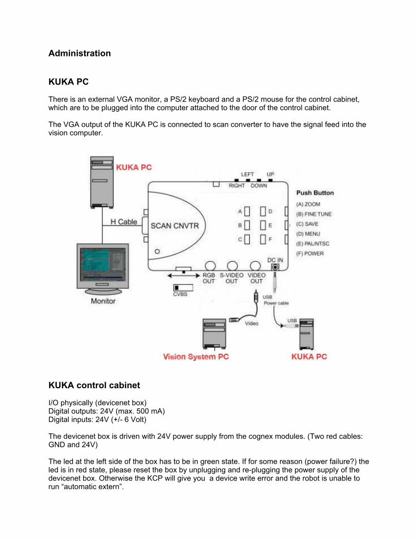
There is an external VGA monitor, a PS/2 keyboard and a PS/2 mouse for the control cabinet, which are to be plugged into the computer attached to the door of the control cabinet.
The VGA output of the KUKA PC is connected to scan converter to have the signal feed into the vision computer.
KUKA control cabinet
I/O physically (devicenet box)Digital outputs: 24V (max. 500 mA)Digital inputs: 24V (+/- 6 Volt)
The devicenet box is driven with 24V power supply from the cognex modules. (Two red cables: GND and 24V)
The led at the left side of the box has to be in green state. If for some reason (power failure?) the led is in red state, please reset the box by unplugging and re-plugging the power supply of the devicenet box. Otherwise the KCP will give you a device write error and the robot is unable to run “automatic extern”.
KUKA system configuration
In order to run the robot in automatic mode the automatic extern interface has to be setup.
We need to have three digital output signals of the device net box connected (wired) to three digital input signals.$IN[6] <-> $OUT[6]$IN[7] <-> $OUT[7]$IN[8] <-> $OUT[8]
Signal to light unit goes from output 1: $OUT[1]
The system variables $CONF_MESS, $EXT_START and $DRIVES_ON are read-only when it comes to programming.For this reason we have to set those variables externally using the “automatic extern” configuration.
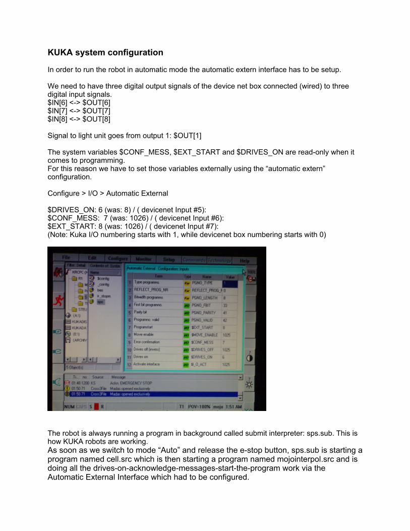
Configure > I/O > Automatic External
$DRIVES_ON: 6 (was: 8) / ( devicenet Input #5):$CONF_MESS: 7 (was: 1026) / ( devicenet Input #6):$EXT_START: 8 (was: 1026) / ( devicenet Input #7):(Note: Kuka I/O numbering starts with 1, while devicenet box numbering starts with 0)
The robot is always running a program in background called submit interpreter: sps.sub. This is how KUKA robots are working. As soon as we switch to mode “Auto” and release the e-stop button, sps.sub is starting a program named cell.src which is then starting a program named mojointerpol.src and is doing all the drives-on-acknowledge-messages-start-the-program work via the Automatic External Interface which had to be configured.

Vision system PC
AMD Athlon 64 3000+, 1.81 Ghz, 512MB RAMSpectra 8 capture card (4 channel, BNC female adapter for video input)Diskdrive (USB) for data transfer to KUKA PCTelephone handle (USB) for Skype callsSerial RS232 cable (crossed) running to control cabinet (KUKA: Com2)
Windows XP Professional SP2 German, licence: 76497-OEM-0053686-12469Vision System ProgramRealVNC for remote managementSkype (Account mojo.sanpedro)
The network IP address is 192.168.0.2. All software including driver installation software is located on drive F: in folder MojoVision. There is a complete backup at an (white) USB-stick dated from 06/02/2007The capture has got 4 BNC adapters from top to bottom:input#0 – camera#1 signalinput#1 – camera#2 signalinput#2 – not usedinput#3 – signal from kuka kcp via scan converter
CPU load is always high due to video frame processing, around 90%.
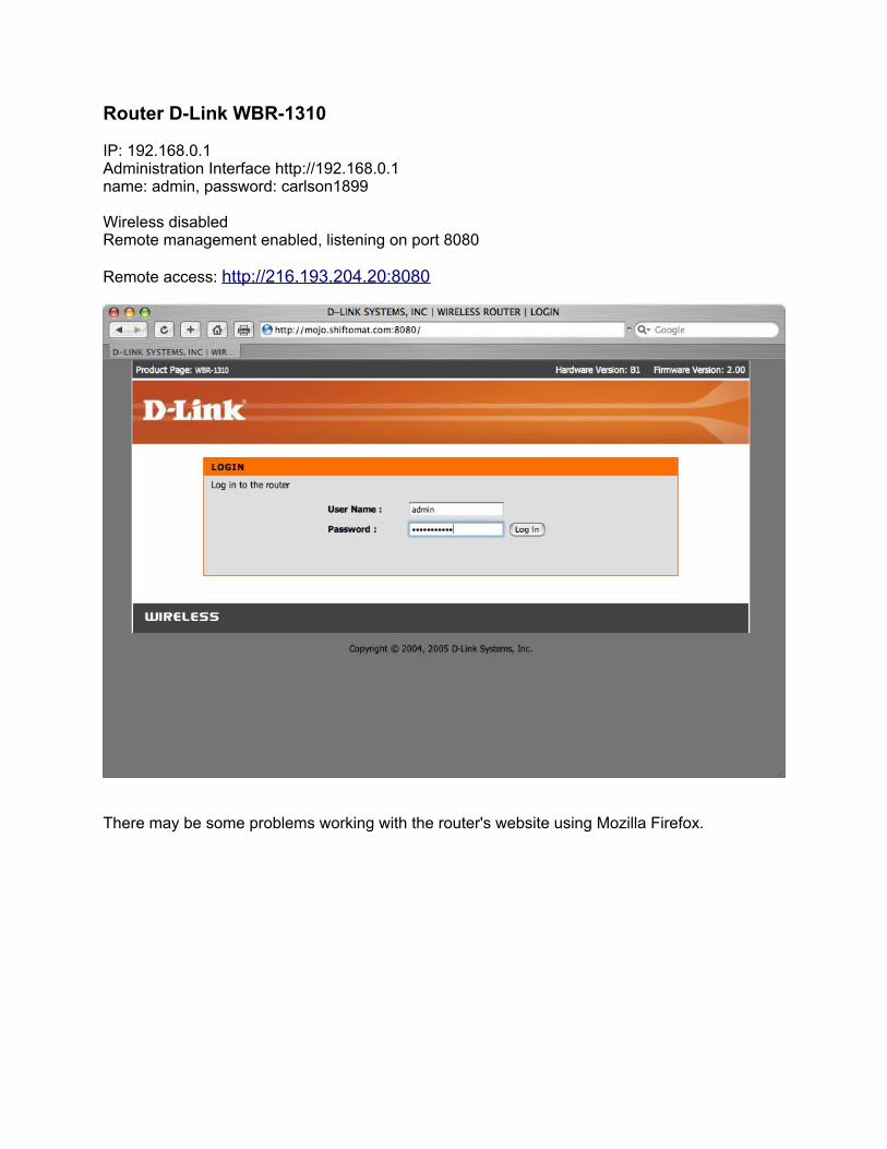
Router D-Link WBR-1310
IP: 192.168.0.1Administration Interface http://192.168.0.1name: admin, password: carlson1899
Wireless disabledRemote management enabled, listening on port 8080
Remote access: http://216.193.204.20:8080
There may be some problems working with the router's website using Mozilla Firefox.
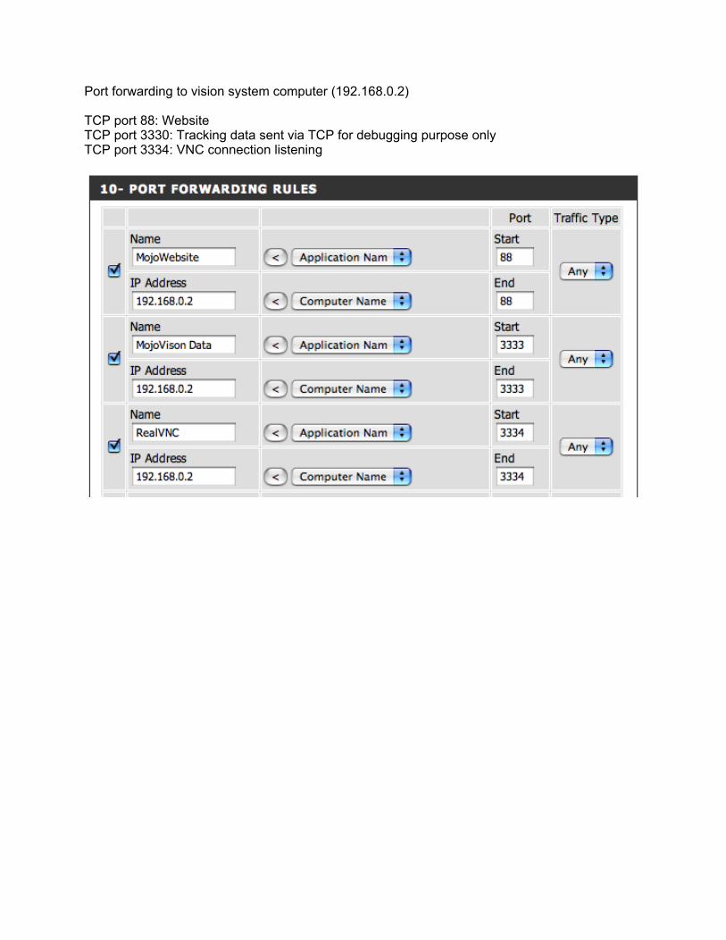
Port forwarding to vision system computer (192.168.0.2)
TCP port 88: WebsiteTCP port 3330: Tracking data sent via TCP for debugging purpose onlyTCP port 3334: VNC connection listening
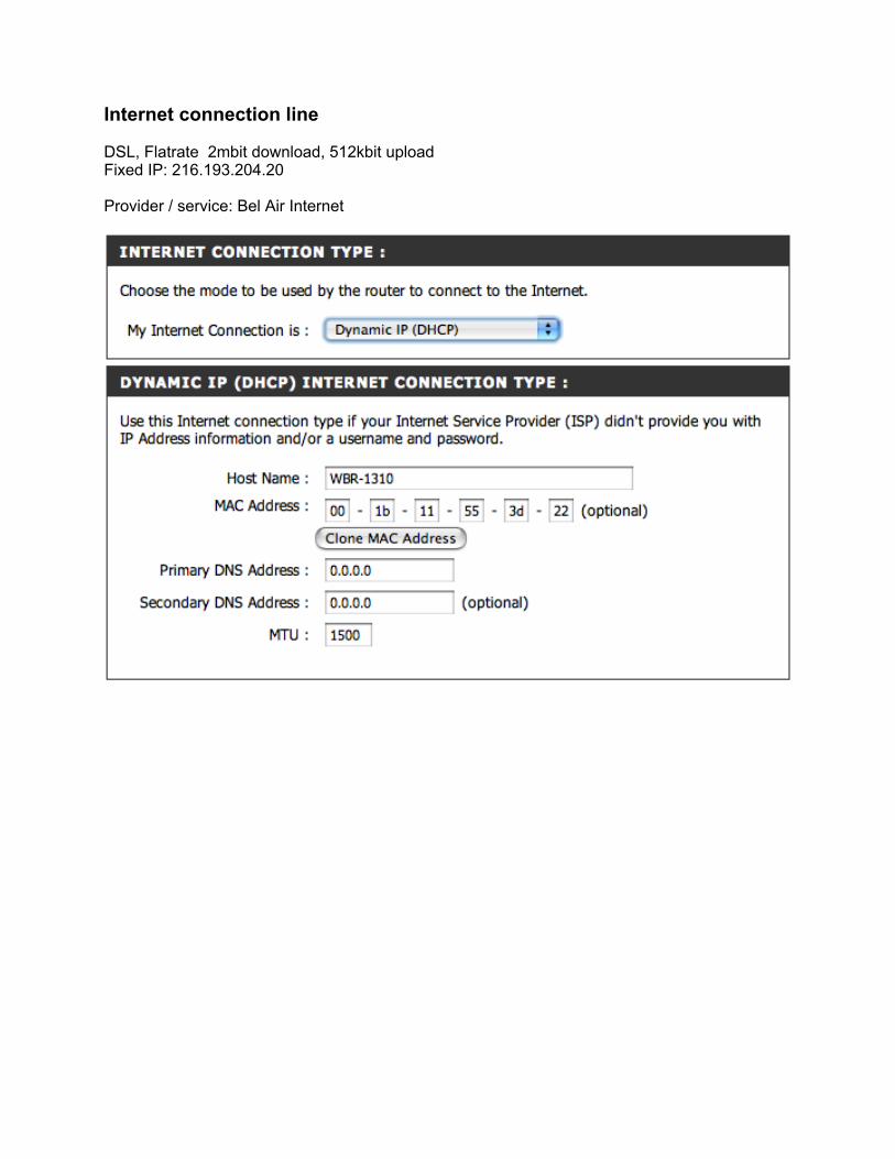
Internet connection line
DSL, Flatrate 2mbit download, 512kbit uploadFixed IP: 216.193.204.20
Provider / service: Bel Air Internet
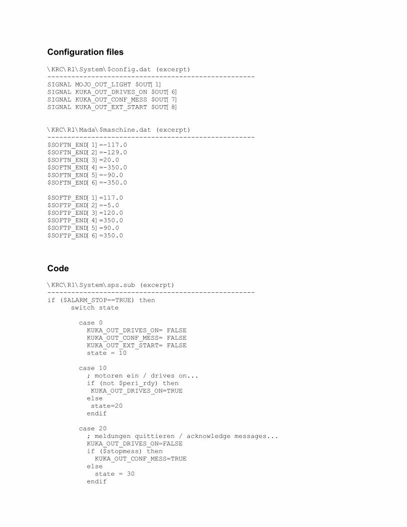
Configuration files
\KRC\R1\System\$config.dat (excerpt)----------------------------------------------------SIGNAL MOJO_OUT_LIGHT $OUT[1]SIGNAL KUKA_OUT_DRIVES_ON $OUT[6]SIGNAL KUKA_OUT_CONF_MESS $OUT[7]SIGNAL KUKA_OUT_EXT_START $OUT[8]
\KRC\R1\Mada\$maschine.dat (excerpt)----------------------------------------------------$SOFTN_END[1]=-117.0$SOFTN_END[2]=-129.0$SOFTN_END[3]=20.0$SOFTN_END[4]=-350.0$SOFTN_END[5]=-90.0$SOFTN_END[6]=-350.0
$SOFTP_END[1]=117.0$SOFTP_END[2]=-5.0$SOFTP_END[3]=120.0$SOFTP_END[4]=350.0$SOFTP_END[5]=90.0$SOFTP_END[6]=350.0
Code
\KRC\R1\System\sps.sub (excerpt)----------------------------------------------------if ($ALARM_STOP==TRUE) then
switch state
case 0 KUKA_OUT_DRIVES_ON= FALSE KUKA_OUT_CONF_MESS= FALSE KUKA_OUT_EXT_START= FALSE state = 10 case 10 ; motoren ein / drives on... if (not $peri_rdy) then KUKA_OUT_DRIVES_ON=TRUE else state=20 endif case 20 ; meldungen quittieren / acknowledge messages... KUKA_OUT_DRIVES_ON=FALSE if ($stopmess) then KUKA_OUT_CONF_MESS=TRUE else state = 30 endif
case 30 ; programm starten / start program... KUKA_OUT_CONF_MESS=FALSE if (not $pro_act) then KUKA_OUT_EXT_START=TRUE else state = 40 endif case 40 KUKA_OUT_EXT_START=FALSE state = 50 default endswitch
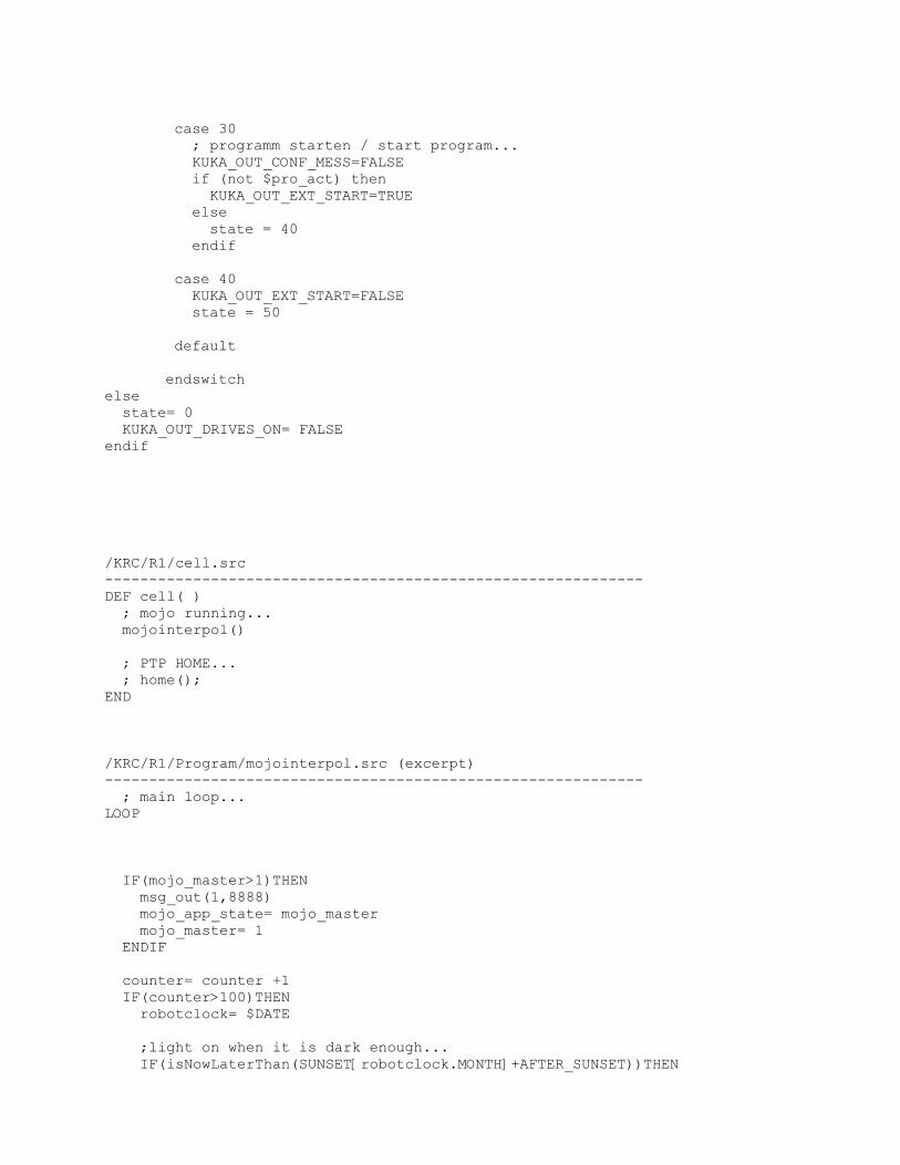
else state= 0 KUKA_OUT_DRIVES_ON= FALSEendif
/KRC/R1/cell.src-------------------------------------------------------------DEF cell( ) ; mojo running... mojointerpol()
; PTP HOME... ; home();END
/KRC/R1/Program/mojointerpol.src (excerpt)------------------------------------------------------------- ; main loop...LOOP
IF(mojo_master>1)THEN msg_out(1,8888) mojo_app_state= mojo_master mojo_master= 1 ENDIF
counter= counter +1 IF(counter>100)THEN robotclock= $DATE
;light on when it is dark enough... IF(isNowLaterThan(SUNSET[robotclock.MONTH]+AFTER_SUNSET))THEN
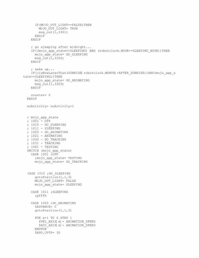
IF(MOJO_OUT_LIGHT==FALSE)THEN MOJO_OUT_LIGHT= TRUE msg_out(1,3301) ENDIF ENDIF
; go sleeping after midnight... IF((mojo_app_state<>SLEEPING) AND (robotclock.HOUR==SLEEPING_HOUR))THEN mojo_app_state= GO_SLEEPING msg_out(1,3302) ENDIF
; wake up... IF((isNowLaterThan(SUNRISE[robotclock.MONTH]+AFTER_SUNRISE))AND(mojo_app_state==SLEEPING))THEN mojo_app_state= GO_ANIMATING msg_out(1,3303) ENDIF
counter= 0 ENDIF
noActivity= noActivity+1
; mojo_app_state ; 1001 - OFF ; 1010 - GO_SLEEPING ; 1011 - SLEEPING ; 1020 - GO_ANIMATING ; 1021 - ANIMATING ; 1030 - GO_TRACKING ; 1031 - TRACKING ; 1041 - TESTING SWITCH (mojo_app_state) CASE 1001 ;OFF ;mojo_app_state= TESTING mojo_app_state= GO_TRACKING
CASE 1010 ;GO_SLEEPING gotoPosition(1,1,3) MOJO_OUT_LIGHT= FALSE mojo_app_state= SLEEPING
CASE 1011 ;SLEEPING ;pfffh
CASE 1020 ;GO_ANIMATING $ADVANCE= 0 gotoPosition(1,1,3)
FOR x=1 TO 6 STEP 1 $VEL_AXIS[x]= ANIMATION_SPEED $ACC_AXIS[x]= ANIMATION_SPEED ENDFOR $APO.CPTP= 30

activity=0 mojo_app_state= ANIMATING
CASE 1021 ;ANIMATING IF(activity>0)THEN mojo_app_state= GO_TRACKING ELSE animationStep= animationStep+1; IF(animationStep>ANIMATION_LENGTH)THEN animationStep= 1 ENDIF
PTP ANIMATION[animationStep] C_PTP ENDIF
CASE 1030 ;GO_TRACKING FOR x=1 TO 6 STEP 1 $VEL_AXIS[x]= TRACKING_SPEED*2 $ACC_AXIS[x]= TRACKING_SPEED*2 ENDFOR gotoPosition(1,1,3)
FOR x=1 TO 6 STEP 1 $VEL_AXIS[x]= TRACKING_SPEED $ACC_AXIS[x]= TRACKING_SPEED ENDFOR $APO.CPTP= 100 $ADVANCE= 1 mojo_app_state= TRACKING
CASE 1031 ;TRACKING rx= TRACKING_X ry= TRACKING_Y
IF(rx>=0)THEN evaluatePosition(rx, ry, row, column, factorX, factorY) f11= R[row, column] f12= R[row, column+1] f21= R[row+1, column] f22= R[row+1, column+1] ELSE evaluatePosition(rx+5000, ry, row, column, factorX, factorY) f11= L[row, column] f12= L[row, column+1] f21= L[row+1, column] f22= L[row+1, column+1] ENDIF
PTP interpolateXY(f11,f12,f21,f22,factorX, factorY) C_PTP rxo= rx ryo= ry IF(noActivity>99) THEN activity= 0 mojo_app_state= GO_ANIMATING ENDIF
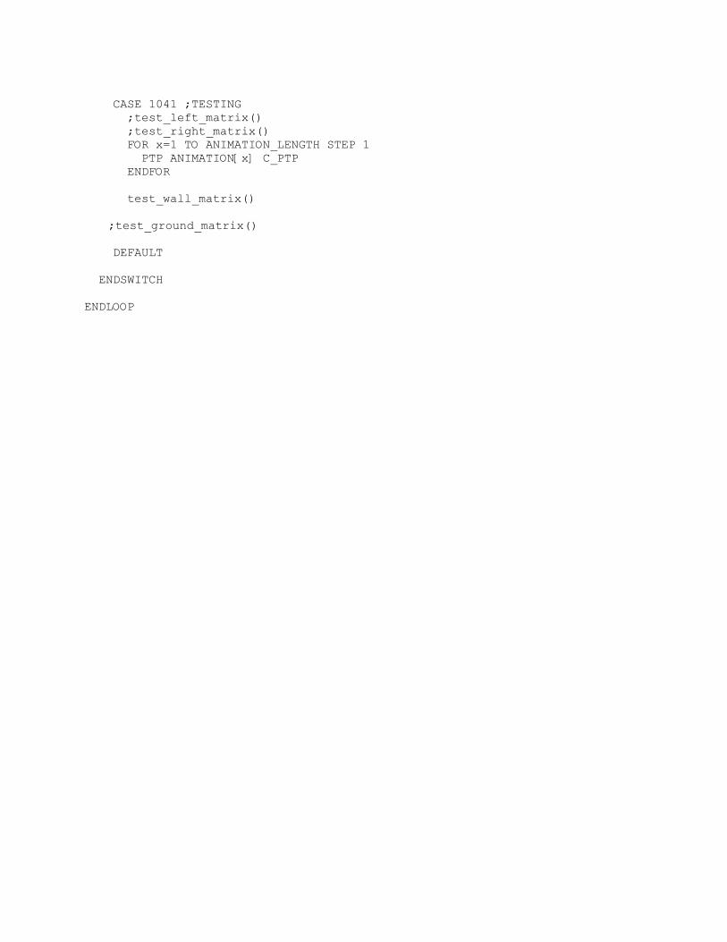
CASE 1041 ;TESTING ;test_left_matrix() ;test_right_matrix() FOR x=1 TO ANIMATION_LENGTH STEP 1 PTP ANIMATION[x] C_PTP ENDFOR
test_wall_matrix() ;test_ground_matrix()
DEFAULT
ENDSWITCH
ENDLOOP
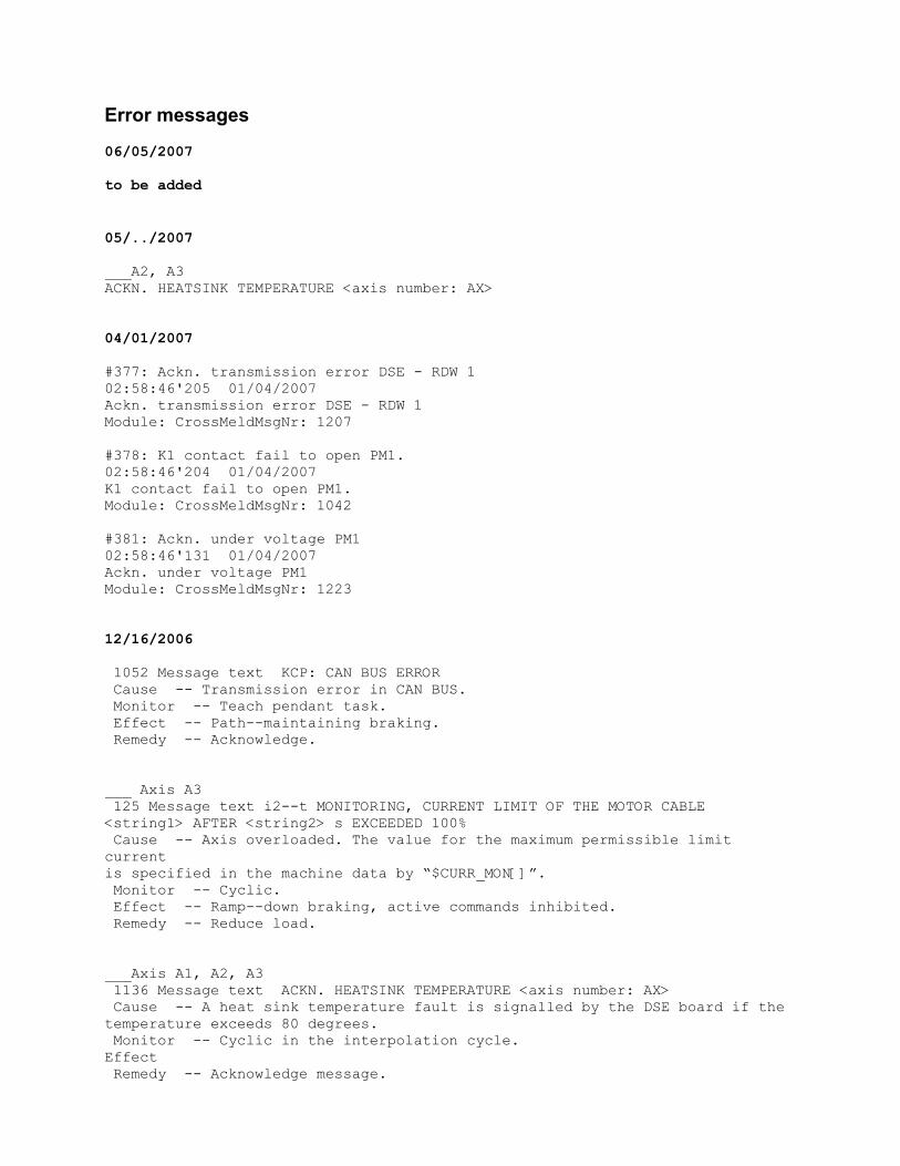
Error messages
06/05/2007
to be added
05/../2007
___A2, A3ACKN. HEATSINK TEMPERATURE <axis number: AX>
04/01/2007
#377: Ackn. transmission error DSE - RDW 102:58:46'205 01/04/2007Ackn. transmission error DSE - RDW 1Module: CrossMeldMsgNr: 1207
#378: K1 contact fail to open PM1.02:58:46'204 01/04/2007K1 contact fail to open PM1.Module: CrossMeldMsgNr: 1042
#381: Ackn. under voltage PM102:58:46'131 01/04/2007Ackn. under voltage PM1Module: CrossMeldMsgNr: 1223
12/16/2006
1052 Message text KCP: CAN BUS ERROR Cause -- Transmission error in CAN BUS. Monitor -- Teach pendant task. Effect -- Path--maintaining braking. Remedy -- Acknowledge.
___ Axis A3 125 Message text i2--t MONITORING, CURRENT LIMIT OF THE MOTOR CABLE<string1> AFTER <string2> s EXCEEDED 100% Cause -- Axis overloaded. The value for the maximum permissible limit currentis specified in the machine data by “$CURR_MON[]”. Monitor -- Cyclic. Effect -- Ramp--down braking, active commands inhibited. Remedy -- Reduce load.
___Axis A1, A2, A3 1136 Message text ACKN. HEATSINK TEMPERATURE <axis number: AX> Cause -- A heat sink temperature fault is signalled by the DSE board if thetemperature exceeds 80 degrees. Monitor -- Cyclic in the interpolation cycle.Effect Remedy -- Acknowledge message.
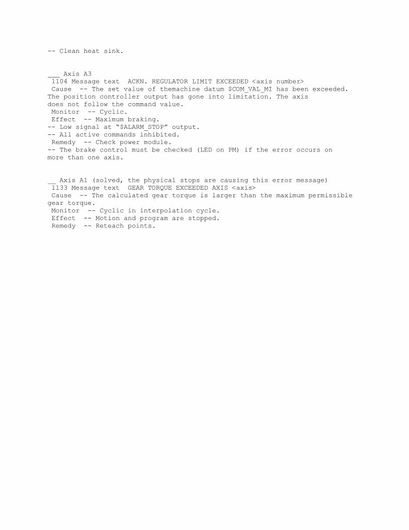
-- Clean heat sink.
___ Axis A3 1104 Message text ACKN. REGULATOR LIMIT EXCEEDED <axis number> Cause -- The set value of themachine datum $COM_VAL_MI has been exceeded.The position controller output has gone into limitation. The axisdoes not follow the command value. Monitor -- Cyclic. Effect -- Maximum braking.-- Low signal at “$ALARM_STOP” output.-- All active commands inhibited. Remedy -- Check power module.-- The brake control must be checked (LED on PM) if the error occurs onmore than one axis.
__ Axis A1 (solved, the physical stops are causing this error message) 1133 Message text GEAR TORQUE EXCEEDED AXIS <axis> Cause -- The calculated gear torque is larger than the maximum permissiblegear torque. Monitor -- Cyclic in interpolation cycle. Effect -- Motion and program are stopped. Remedy -- Reteach points.