operation - 4wd mechanix magazine, video combined pdfs.pdf · 2006 - tj - jeep wrangler - 4.0l 6...
TRANSCRIPT

1
2006 - TJ - JEEP WRANGLER - 4.0L 6 CYL (MPI)
21 - Transmission and Transfer Case/Automatic - 42RLE/Operation
OPERATION
The 42RLE transmission ratios are:
GEAR RATIO
First 2.84 : 1
Second 1.57 : 1
Third 1.00 : 1
Overdrive 0.69 : 1
Reverse 2.21 : 1
FIRST GEAR POWERFLOW
In first gear range, torque input is through the underdrive clutch (1) to the underdrive hub assembly. The underdrive hubis splined to the rear sun gear. When the underdrive clutch is applied, it rotates the underdrive hub and rear sun gear.The L/R clutch (2) is applied to hold the front carrier/rear annulus assembly. The rear sun gear drives the rear planetarypinion gears. The rear planetary pinion gears are forced to walk around the inside of the stationary rear annulus gear. Thepinions are pinned to the rear carrier and cause the rear carrier assembly to rotate as they walk around the annulus gear.

2
This provides the torque output for first gear. The other planetary gearset components are freewheeling. The first gear ratiois 2.84:1.
SECOND GEAR POWERFLOW
Second gear is achieved by having both planetary gear sets contribute to torque multiplication. As in first gear, torque inputis through the underdrive clutch (1) to the rear sun gear. The 2/4 clutch (2) is applied to hold the front sun gear stationary.The rotating rear sun gear turns the rear planetary pinions. The rear pinions rotate the rear annulus/front carrier assembly.The pinions of the front carrier walk around the stationary front sun gear. This transmits torque to the front annulus/rearcarrier assembly, which provides output torque and a gear ratio of 1.57:1.
3
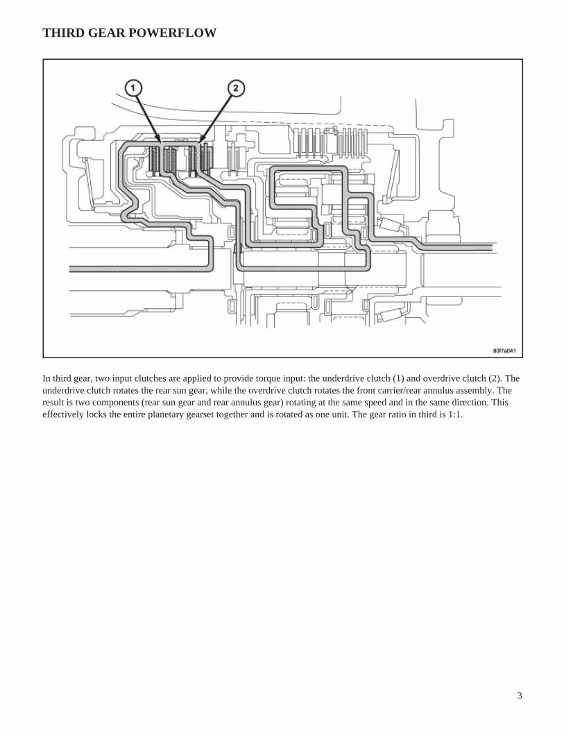
THIRD GEAR POWERFLOW
In third gear, two input clutches are applied to provide torque input: the underdrive clutch (1) and overdrive clutch (2). Theunderdrive clutch rotates the rear sun gear, while the overdrive clutch rotates the front carrier/rear annulus assembly. Theresult is two components (rear sun gear and rear annulus gear) rotating at the same speed and in the same direction. Thiseffectively locks the entire planetary gearset together and is rotated as one unit. The gear ratio in third is 1:1.

4
FOURTH GEAR POWERFLOW
In fourth gear input torque is through the overdrive clutch (1) which drives the front carrier. The 2/4 clutch (2) is appliedto hold the front sun gear. As the overdrive clutch rotates the front carrier, it causes the pinions of the front carrier to walkaround the stationary front sun gear. This causes the front carrier pinions to turn the front annulus/rear carrier assemblywhich provides output torque. In fourth gear, transmission output speed is more than engine input speed. This situation iscalled overdrive and the gear ratio is 0.69:1.

5
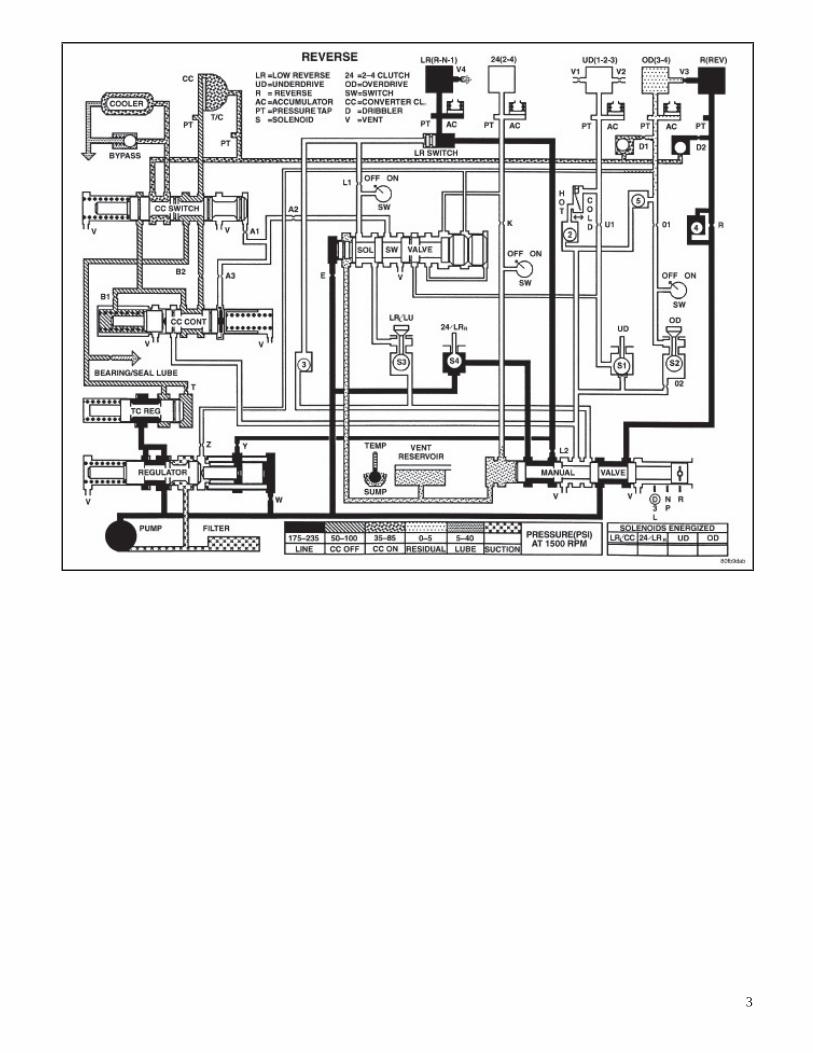
REVERSE GEAR POWERFLOW
In reverse, input power is through the reverse clutch (1). When applied, the reverse clutch drives the front sun gear throughthe overdrive hub and shaft. The L/R clutch (2) is applied to hold the front carrier/rear annulus assembly stationary. Thefront carrier is being held by the L/R clutch so the pinions are forced to rotate the front annulus/rear carrier assembly in thereverse direction. Output torque is provided, in reverse, with a gear ratio of 2.21:1.
1
2006 - TJ - JEEP WRANGLER - 4.0L 6 CYL (MPI)
21 - Transmission and Transfer Case/Automatic - 42RLE/Schematics and Diagrams
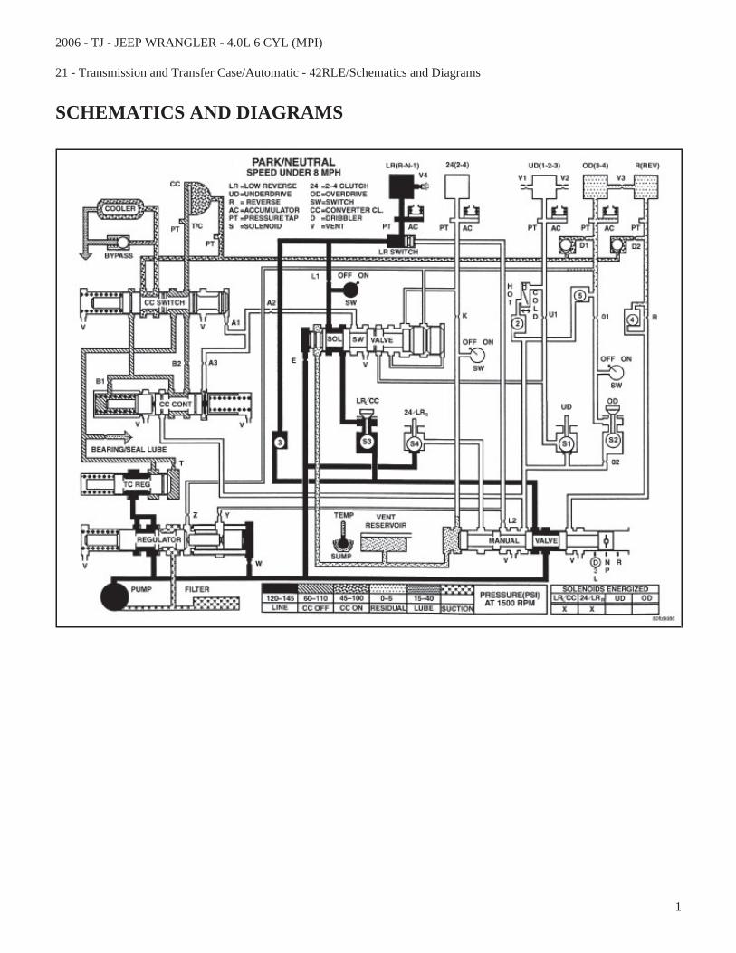
SCHEMATICS AND DIAGRAMS

2
3

4

5

6

7

8

9

10

11

12

13

1
2006 - TJ - JEEP WRANGLER - 4.0L 6 CYL (MPI)
21 - Transmission and Transfer Case/Automatic - 42RLE/Diagnosis and Testing
DIAGNOSIS AND TESTING - HYDRAULIC PRESSURE TESTS
Pressure testing is a very important step in the diagnosticprocedure. These tests usually reveal the cause of mosttransmission problems.
Before performing pressure tests, be certain that fluidlevel and condition, and shift cable adjustments havebeen checked and approved. Fluid must be at operatingtemperature ,150 to 200 degrees F. ( 65 - 93 degrees C.).
Install an engine tachometer, raise vehicle on hoist whichallows the wheels to turn, and position tachometer so it canbe read.
Using special adapters L-4559A , attach 300 psi gauge(s)C-3293-SP to the port(s) required for test being conducted.
Test port locations are shown in the Pressure Taps graphic.
TEST ONE - SELECTOR IN MANUAL 1 (1st Gear)
NOTE: This test checks pump output, pressure regulation and condition of the low/reverse clutch hydraulic circuitand shift schedule.
1. Attach pressure gauge to the low/reverse clutch tap.
2. Move selector lever to the MANUAL 1 position.
3. Allow vehicle wheels to turn and increase throttle opening to achieve an indicated vehicle speed to 20 mph.
4. Low/reverse clutch pressure should read 115 to 145 psi.
TEST TWO - SELECTOR IN MANUAL 2 (Second Gear)
NOTE: This test checks the underdrive clutch hydraulic circuit as well as the shift schedule.
1. Attach gauge to the underdrive clutch tap.
2. Move selector lever to the MANUAL 2 position.
3. Allow vehicle wheels to turn and increase throttle opening to achieve an indicated vehicle speed of 30 mph.
4. In second gear the underdrive clutch pressure should read 110 to 145 psi.
TEST TWO A - SELECTOR IN DRIVE (OD ON - Fourth Gear)
NOTE: This test checks the underdrive clutch hydraulic circuit as well as the shift schedule.

2
1. Attach gauge to the underdrive clutch tap.
2. Move selector lever to the DRIVE position. Verfy that the OD switch is ON.
3. Allow wheels to rotate freely and increase throttle opening to achieve an indicated speed of 40 mph.
4. Underdrive clutch pressure should read below 5 psi. If not, than either the solenoid assembly or controller is at fault.
TEST THREE - SELECTOR IN DRIVE (OD OFF - Third and Second Gear)
NOTE: This test checks the overdrive clutch hydraulic circuit as well as the shift schedule.
1. Attach gauge to the overdrive clutch tap.
2. Move selector lever to the DRIVE position.
3. Allow vehicle wheels to turn and increase throttle opening to achieve an indicated vehicle speed of 20 mph.
4. Overdrive clutch pressure should read 74 to 95 psi.
5. Move selector lever to the DRIVE position and increase indicated vehicle speed to 30 mph.
6. The vehicle should be in second gear and overdrive clutch pressure should be less than 5 psi.
TEST FOUR - SELECTOR IN DRIVE (OD ON - Fourth Gear)
NOTE: This test checks the 2/4 clutch hydraulic circuit.
1. Attach gauge to the 2/4 clutch tap.
2. Move selector lever to the DRIVE position.
3. Allow vehicle front wheels to turn and increase throttle opening to achieve an indicated vehicle speed of 30 mph.Vehicle should be in fourth gear.
4. The 2/4 clutch pressure should read 75 to 95 psi.
TEST FIVE-SELECTOR IN DRIVE (OD ON - Fourth Gear, CC on)
NOTE: These tests check the torque converter clutch hydraulic circuit.
1. Attach gauge to the torque converter clutch off pressure tap.
2. Move selector lever to the DRIVE position.
3. Allow vehicle wheels to turn and increase throttle opening to achieve an indicated vehicle speed of 50 mph. Vehicleshould be in 4th gear, CC on.
CAUTION: Both wheels must turn at the same speed.
4. Torque converter clutch off pressure should be less than 5 psi.
5. Now attach the gauge to the torque converter clutch on pressure tap.

3
6. Move selector to the OD position.
7. Allow vehicle wheels to turn and increase throttle opening to achieve an indicated vehicle speed of 50 mph.
8. Verify the torque converter clutch is applied mode using the RPM display of the DRB scan tool.
9. Torque converter clutch on pressure should be 60-90 psi.
TEST SIX-SELECTOR IN REVERSE
NOTE: This test checks the reverse clutch hydraulic circuit.
1. Attach gauge to the reverse and low/reverse clutch tap.
2. Move selector lever to the REVERSE position.
3. Read reverse clutch pressure with output stationary (foot on brake) and throttle opened to achieve 1500 rpm.
4. Reverse and low/reverse clutch pressure should read 165 to 235 psi.
TEST RESULT INDICATIONS
1. If proper line pressure is found in any one test, the pump and pressure regulator are working properly.
2. Low pressure in all positions indicates a defective pump, a clogged filter, or a stuck pressure regulator valve.
3. Clutch circuit leaks are indicated if pressures do not fall within the specified pressure range.
4. If the overdrive clutch pressure is greater than 5 psi in 6 of Test Three, a worn reaction shaft seal ring or a defectivesolenoid assembly is indicated.
5. If the underdrive clutch pressure is greater than 5 psi in 4 of Test Two-A, a defective solenoid/pressure switchassembly or controller is the cause.
ALL PRESSURE SPECIFICATIONS ARE PSI (on hoist, with wheels free to turn)
PRESSURE TAPSGear SelectorPosition
Actual Gear
UnderdriveClutch
OverdriveClutch
ReverseClutch
TorqueConverter
ClutchOff
TorqueConverter
ClutchOn
2/4Clutch
Low/ReverseClutch
PARK - 0 mph * PARK 0-2 0-5 0-2 60-110 45-100 0-2 115-145
REVERSE - 0 mph * REVERSE 0-2 0-7 165-235 50-100 35-85 0-2 165-235
NEUTRAL - 0 mph * NEUTRAL 0-2 0-5 0-2 60-110 45-100 0-2 115-145
Low - 20 mph # FIRST 110-145 0-5 0-2 60-110 45-100 0-2 115-145
Third - 30 mph # SECOND 110-145 0-5 0-2 60-110 45-100 115-145 0-2
Third - 45 mph # DIRECT 75-95 75-95 0-2 60-90 45-80 0-2 0-2
OD - 30 mph # OVERDRIVE 0-2 75-95 0-2 60-90 45-80 75-95 0-2

4
PRESSURE TAPSGear SelectorPosition
Actual Gear
UnderdriveClutch
OverdriveClutch
ReverseClutch
TorqueConverter
ClutchOff
TorqueConverter
ClutchOn
2/4Clutch
Low/ReverseClutch
OD - 50 mph # OVERDRIVEWITH TCC
0-2 75-95 0-2 0-5 60-95 75-95 0-2
* Engine Speed at 1500 rpm
# CAUTION: Both wheels must be turning at same speed.
1
2006 - TJ - JEEP WRANGLER - 4.0L 6 CYL (MPI)
21 - Transmission and Transfer Case/Automatic - 42RLE/ASSEMBLY, Transmission Solenoid and Pressure Switch/Operation
OPERATION
SOLENOIDS
The solenoids receive electrical power from the Transmission Control Relay through a single wire. The TCM energizes oroperates the solenoids individually by grounding the return wire of the solenoid needed. When a solenoid is energized, thesolenoid valve shifts, and a fluid passage is opened or closed (vented or applied), depending on its default operating state.The result is an apply or release of a frictional element.
The 2/4 and UD solenoids are normally applied, which allows fluid to pass through in their relaxed or “off” state. Bydesign, this allows transmission limp-in (P,R,N,2) in the event of an electrical failure.
The continuity of the solenoids and circuits are periodically tested. Each solenoid is turned on or off depending on itscurrent state. An inductive spike should be detected by the TCM during this test. If no spike is detected, the circuit is testedagain to verify the failure. In addition to the periodic testing, the solenoid circuits are tested if a speed ratio or pressureswitch error occurs.
PRESSURE SWITCHES
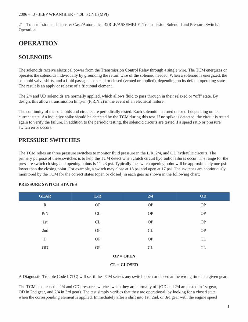
The TCM relies on three pressure switches to monitor fluid pressure in the L/R, 2/4, and OD hydraulic circuits. Theprimary purpose of these switches is to help the TCM detect when clutch circuit hydraulic failures occur. The range for thepressure switch closing and opening points is 11-23 psi. Typically the switch opening point will be approximately one psilower than the closing point. For example, a switch may close at 18 psi and open at 17 psi. The switches are continuouslymonitored by the TCM for the correct states (open or closed) in each gear as shown in the following chart:
PRESSURE SWITCH STATES
GEAR L/R 2/4 OD
R OP OP OP
P/N CL OP OP
1st CL OP OP
2nd OP CL OP
D OP OP CL
OD OP CL CL
OP = OPEN
CL = CLOSED
A Diagnostic Trouble Code (DTC) will set if the TCM senses any switch open or closed at the wrong time in a given gear.
The TCM also tests the 2/4 and OD pressure switches when they are normally off (OD and 2/4 are tested in 1st gear,OD in 2nd gear, and 2/4 in 3rd gear). The test simply verifies that they are operational, by looking for a closed statewhen the corresponding element is applied. Immediately after a shift into 1st, 2nd, or 3rd gear with the engine speed

2
above 1000 rpm, the TCM momentarily turns on element pressure to the 2/4 and OD clutch circuits to identify thatthe appropriate switch has closed. If it doesn't close, it is tested again. If the switch fails to close the second time, theappropriate Diagnostic Trouble Code (DTC) will set.

1
2006 - TJ - JEEP WRANGLER - 4.0L 6 CYL (MPI)
21 - Transmission and Transfer Case/Automatic - 42RLE/SENSOR, Speed, Output/Operation
OPERATION
The Input Speed Sensor provides information on how fast the input shaft is rotating. As the teeth of the input clutch hubpass by the sensor coil, an AC voltage is generated and sent to the TCM. The TCM interprets this information as inputshaft rpm.
The Output Speed Sensor generates an AC signal in a similar fashion, though its coil is excited by rotation of the rearplanetary carrier lugs. The TCM interprets this information as output shaft rpm.
The TCM compares the input and output speed signals to determine the following:
• Transmission gear ratio
• Speed ratio error detection
• CVI calculation
The TCM also compares the input speed signal and the engine speed signal to determine the following:
• Torque converter clutch slippage
• Torque converter element speed ratio