operation and installation manual f90s / f90m · ball valve or the t-piece set the depth adjustment...
TRANSCRIPT
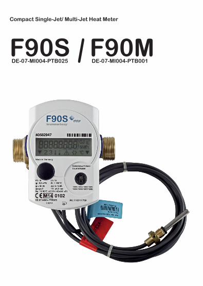
Compact Single-Jet/ Multi-Jet Heat Meter
F90SDE-07-MI004-PTB025
F90MDE-07-MI004-PTB001
2
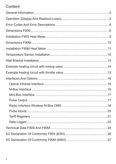
ContentGeneral Information ���������������������������������������������������������������������������������������3
Operation (Display And Readout-Loops) �������������������������������������������������������4
Error Codes And Error Descriptions ��������������������������������������������������������������6
Dimensions F90S ������������������������������������������������������������������������������������������8
Installation F90S Heat Meter �������������������������������������������������������������������������9
Dimensions F90M����������������������������������������������������������������������������������������10
Installation F90M Heat Meter ����������������������������������������������������������������������11
Temperature Sensor Installation ������������������������������������������������������������������12
Wall Bracket Installation ������������������������������������������������������������������������������13
Example heating circuit with mixing valve ���������������������������������������������������14
Example heating circuit with throttle valve���������������������������������������������������15
Interfaces And Options ��������������������������������������������������������������������������������16
Optical Infrared Interface �������������������������������������������������������������������������16
M-Bus Interface ���������������������������������������������������������������������������������������16
Mini-Bus Interface ������������������������������������������������������������������������������������17
Pulse Output ��������������������������������������������������������������������������������������������17
Radio Interface Wireless M-Bus OMS �����������������������������������������������������18
Pulse Inputs ���������������������������������������������������������������������������������������������20
Tariff Registers �����������������������������������������������������������������������������������������21
Data Logger ���������������������������������������������������������������������������������������������22
Technical Data F90S And F90M ������������������������������������������������������������������24
EC Declaration Of Conformity F90S (ESH) �������������������������������������������������26
EC Declaration Of Conformity F90M (MSH)������������������������������������������������27
3
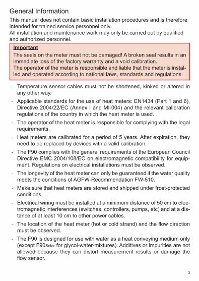
General InformationThis manual does not contain basic installation procedures and is therefore intended for trained service personnel only�All installation and maintenance work may only be carried out by qualified and authorized personnel�
ImportantThe seals on the meter must not be damaged! A broken seal results in an immediate loss of the factory warranty and a void calibration�The operator of the meter is responsible and liable that the meter is instal-led and operated according to national laws, standards and regulations�
- Temperature sensor cables must not be shortened, kinked or altered in any other way�
- Applicable standards for the use of heat meters: EN1434 (Part 1 and 6), Directive 2004/22/EC (Annex I and MI-004) and the relevant calibration regulations of the country in which the heat meter is used�
- The operator of the heat meter is responsible for complying with the legal requirements�
- Heat meters are calibrated for a period of 5 years� After expiration, they need to be replaced by devices with a valid calibration�
- The F90 complies with the general requirements of the European Council Directive EMC 2004/108/EC on electromagnetic compatibility for equip-ment� Regulations on electrical installations must be observed�
- The longevity of the heat meter can only be guaranteed if the water quality meets the conditions of AGFW-Recommendation FW-510�
- Make sure that heat meters are stored and shipped under frost-protected conditions�
- Electrical wiring must be installed at a minimum distance of 50 cm to elec-tromagnetic interferences (switches, controllers, pumps, etc) and at a dis-tance of at least 10 cm to other power cables�
- The location of the heat meter (hot or cold strand) and the flow direction must be observed�
- The F90 is designed for use with water as a heat conveying medium only (except F90Solar for glycol-water-mixtures)� Additives or impurities are not allowed because they can distort measurement results or damage the flow sensor�
4
Operation (Display And Readout-Loops)
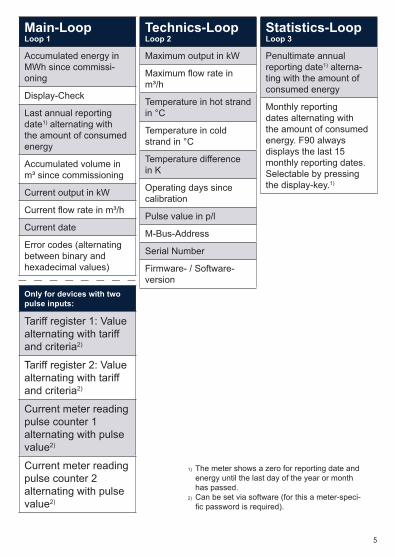
The F90 has a liquid crystal display with 8 digits and additional special characters� The measured and stored values are summarized in three readout-loops� All data can be read out by pressing the display-key�
The accumulated heat energy since commissioning is shown in the main loop (loop 1) by default�
You can toggle between the three given loops by pressing the display-key for more than 4 seconds� The current loop is indicated by the loop number on the lower rim of the display (only loop 2 and 3)� Hold the display-key pressed until the desired loop number appears on the display�
Within a loop you can toggle between the different stored values by briefly pressing the display-key�
When the display-key is not pressed within a minute, the F90 switches back to its default display�
The adjacent table gives you an overview about the possible readouts within each loop�
5
Main-LoopLoop 1
Accumulated energy in MWh since commissi-oning
Display-Check
Last annual reporting date1) alternating with the amount of consumed energy
Accumulated volume in m³ since commissioning
Current output in kW
Current flow rate in m³/h
Current date
Error codes (alternating between binary and hexadecimal values)
Only for devices with two pulse inputs:
Tariff register 1: Value alternating with tariff and criteria2)
Tariff register 2: Value alternating with tariff and criteria2)
Current meter reading pulse counter 1 alternating with pulse value2)
Current meter reading pulse counter 2 alternating with pulse value2)
Technics-LoopLoop 2
Maximum output in kW
Maximum flow rate in m³/h
Temperature in hot strand in °C
Temperature in cold strand in °C
Temperature difference in K
Operating days since calibration
Pulse value in p/l
M-Bus-Address
Serial Number
Firmware- / Software-version
Statistics-LoopLoop 3
Penultimate annual reporting date1) alterna-ting with the amount of consumed energy
Monthly reporting dates alternating with the amount of consumed energy� F90 always displays the last 15 monthly reporting dates� Selectable by pressing the display-key�1)
1) The meter shows a zero for reporting date and energy until the last day of the year or month has passed�
2) Can be set via software (for this a meter-speci-fic password is required).
6
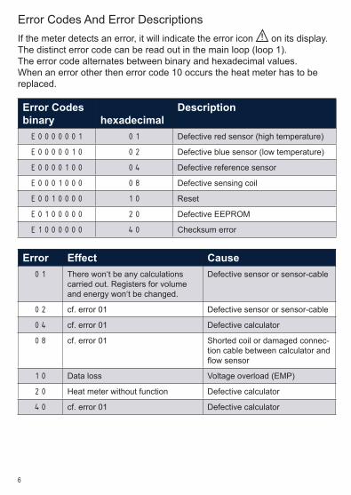
Error Codes And Error DescriptionsIf the meter detects an error, it will indicate the error icon ! on its display�The distinct error code can be read out in the main loop (loop 1)�The error code alternates between binary and hexadecimal values�When an error other then error code 10 occurs the heat meter has to be replaced�
Error Codesbinary hexadecimal
Description
E0000001 01 Defective red sensor (high temperature)
E0000010 02 Defective blue sensor (low temperature)
E0000100 04 Defective reference sensor
E0001000 08 Defective sensing coil
E0010000 10 Reset
E0100000 20 Defective EEPROM
E1000000 40 Checksum error
Error Effect Cause01 There won‘t be any calculations
carried out� Registers for volume and energy won‘t be changed�
Defective sensor or sensor-cable
02 cf� error 01 Defective sensor or sensor-cable
04 cf� error 01 Defective calculator
08 cf� error 01 Shorted coil or damaged connec-tion cable between calculator and flow sensor
10 Data loss Voltage overload (EMP)
20 Heat meter without function Defective calculator
40 cf� error 01 Defective calculator

7
Notes
8
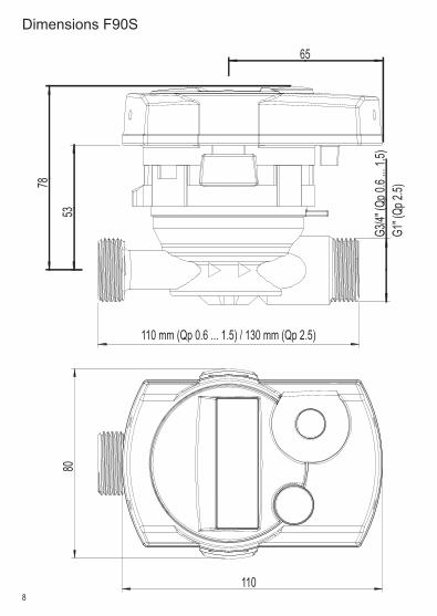
Dimensions F90S
53
78
G3/4"
(Qp 0
.6 ...
1.5)
G1" (
Qp 2.
5)
110 mm (Qp 0.6 ... 1.5) / 130 mm (Qp 2.5)
65
110
80
9
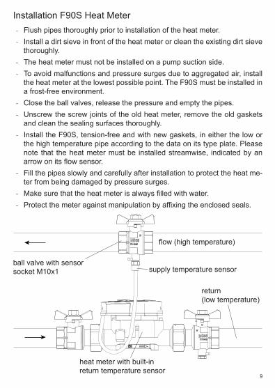
Installation F90S Heat Meter - Flush pipes thoroughly prior to installation of the heat meter� - Install a dirt sieve in front of the heat meter or clean the existing dirt sieve
thoroughly� - The heat meter must not be installed on a pump suction side� - To avoid malfunctions and pressure surges due to aggregated air, install
the heat meter at the lowest possible point� The F90S must be installed in a frost-free environment�
- Close the ball valves, release the pressure and empty the pipes� - Unscrew the screw joints of the old heat meter, remove the old gaskets
and clean the sealing surfaces thoroughly� - Install the F90S, tension-free and with new gaskets, in either the low or
the high temperature pipe according to the data on its type plate� Please note that the heat meter must be installed streamwise, indicated by an arrow on its flow sensor�
- Fill the pipes slowly and carefully after installation to protect the heat me-ter from being damaged by pressure surges�
- Make sure that the heat meter is always filled with water� - Protect the meter against manipulation by affixing the enclosed seals�
flow (high temperature)
return(low temperature)
supply temperature sensor
heat meter with built-inreturn temperature sensor
ball valve with sensorsocket M10x1
10
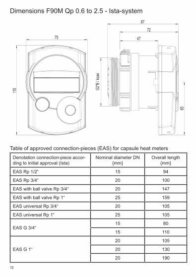
Table of approved connection-pieces (EAS) for capsule heat meters
Denotation connection-piece accor-ding to initial approval (Ista)
Nominal diameter DN {mm}
Overall length {mm}
EAS Rp 1/2“ 15 94
EAS Rp 3/4“ 20 100
EAS with ball valve Rp 3/4“ 20 147
EAS with ball valve Rp 1“ 25 159
EAS universal Rp 3/4“ 20 105
EAS universal Rp 1“ 25 105
EAS G 3/4“15 80
15 110
EAS G 1“
20 105
20 130
20 190
Dimensions F90M Qp 0�6 to 2�5 - Ista-system11
0
75 47
72
87
65
G2“B
/ koa
x
11
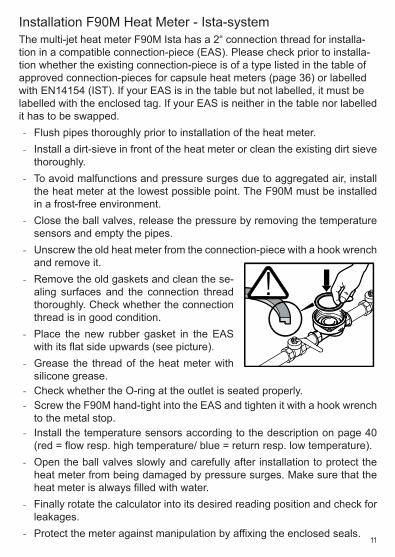
Installation F90M Heat Meter - Ista-systemThe multi-jet heat meter F90M Ista has a 2“ connection thread for installa-tion in a compatible connection-piece (EAS)� Please check prior to installa-tion whether the existing connection-piece is of a type listed in the table of approved connection-pieces for capsule heat meters (page 36) or labelled with EN14154 (IST)� If your EAS is in the table but not labelled, it must be labelled with the enclosed tag� If your EAS is neither in the table nor labelled it has to be swapped�
- Flush pipes thoroughly prior to installation of the heat meter� - Install a dirt-sieve in front of the heat meter or clean the existing dirt sieve
thoroughly� - To avoid malfunctions and pressure surges due to aggregated air, install
the heat meter at the lowest possible point� The F90M must be installed in a frost-free environment�
- Close the ball valves, release the pressure by removing the temperature sensors and empty the pipes�
- Unscrew the old heat meter from the connection-piece with a hook wrench and remove it�
- Remove the old gaskets and clean the se-aling surfaces and the connection thread thoroughly� Check whether the connection thread is in good condition�
- Place the new rubber gasket in the EAS with its flat side upwards (see picture)�
- Grease the thread of the heat meter with silicone grease�
- Check whether the O-ring at the outlet is seated properly� - Screw the F90M hand-tight into the EAS and tighten it with a hook wrench
to the metal stop� - Install the temperature sensors according to the description on page 40
(red = flow resp� high temperature/ blue = return resp� low temperature)� - Open the ball valves slowly and carefully after installation to protect the
heat meter from being damaged by pressure surges� Make sure that the heat meter is always filled with water�
- Finally rotate the calculator into its desired reading position and check for leakages�
- Protect the meter against manipulation by affixing the enclosed seals�
12
Temperature Sensor Installation F90S And F90M-Ista - The temperature sensors are marked with colored type labels, red for
installation in the high temperature strand and blue for installation in the low temperature strand�
- With the F90S one of the two sensors is pre-installed� Which one de-pends on the type of the heat meter (installation in low or hot temperature strand); cf� type label� Normally the blue labelled sensor is pre-installed in the flow sensor and secured with a seal�
- The free temperature sensor (normally the red one) can be installed into a ball valve with sensor socket or a T-piece-adapter with a M10x1 thread�
- According to EN1434-2 it is recommended for pipe sizes ≤ DN25 to install temperature sensors only direct immersed, without using a pocket�
- The temperature sensor has to be secured against manipulation with a seal� The connecting cables must not be shortened or lengthened�
- Close the ball valves, unscrew the screwcap of the old temperature sen-sor and remove it�
- Remove old O-ring and make sure not to leave any residues� - Pull off the O-ring and adjust the new temperature sensor to the required
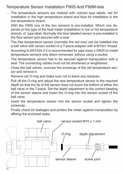
depth so that the tip of the sensor does not touch the bottom of either the ball valve or the T-piece� Set the depth adjustment to the correct beading of the sensor sleeve and insert the O-ring into the sensor socket of the ball valve�
- Insert the temperature sensor into the sensor socket and tighten the screwcap�
- Finally check for leakages and protect the meter against manipulation by affixing the enclosed seals�
ball valve sensor socket M10 x 1 mm
O-ring
sensor sleeve screw joint
depth adjustment
13
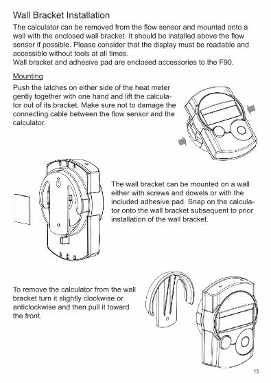
Wall Bracket InstallationThe calculator can be removed from the flow sensor and mounted onto a wall with the enclosed wall bracket. It should be installed above the flow sensor if possible� Please consider that the display must be readable and accessible without tools at all times�Wall bracket and adhesive pad are enclosed accessories to the F90�
MountingPush the latches on either side of the heat meter gently together with one hand and lift the calcula-tor out of its bracket� Make sure not to damage the connecting cable between the flow sensor and the calculator�
The wall bracket can be mounted on a wall either with screws and dowels or with the included adhesive pad� Snap on the calcula-tor onto the wall bracket subsequent to prior installation of the wall bracket�
To remove the calculator from the wall bracket turn it slightly clockwise or anticlockwise and then pull it toward the front�
14
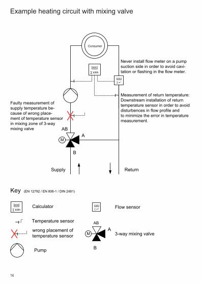
Example heating circuit with mixing valve
Consumer
A
B
AB
ReturnSupply
M
000
∑ kWh
000
∑ m3
Measurement of return temperature:Downstream installation of returntemperature sensor in order to avoiddisturbences in flow profile andto minimize the error in temperaturemeasurement.
Faulty measurement ofsupply temperature be-cause of wrong place-ment of temperature sensorin mixing zone of 3-waymixing valve
000
∑ m3 Flow sensor
3-way mixing valve
ABA
M
B
000
∑ kWhCalculator
Temperature sensor
Pump
wrong placement oftemperature sensor
Key (EN 12792 / EN 806-1 / DIN 2481)
Never install flow meter on a pumpsuction side in order to avoid cavi-tation or flashing in the flow meter.
15
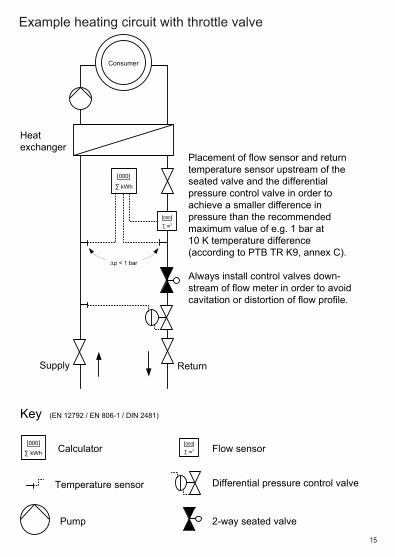
Example heating circuit with throttle valve
Supply Return
000
∑ kWh
000
∑ m3
Heatexchanger
Consumer
∆p < 1 bar
000
∑ kWh000
∑ m3Calculator Flow sensor
Temperature sensor
Pump
Key (EN 12792 / EN 806-1 / DIN 2481)
Differential pressure control valve
2-way seated valve
Placement of flow sensor and returntemperature sensor upstream of theseated valve and the differentialpressure control valve in order toachieve a smaller difference inpressure than the recommendedmaximum value of e.g. 1 bar at10 K temperature difference(according to PTB TR K9, annex C).
Always install control valves down-stream of flow meter in order to avoidcavitation or distortion of flow profile.
16
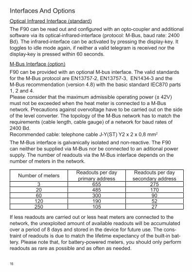
Interfaces And OptionsOptical Infrared Interface (standard)The F90 can be read out and configured with an opto-coupler and additional software via its optical-infrared-interface (protocol: M-Bus, baud rate: 2400 Bd)� The infrared-interface can be activated by pressing the display-key� It toggles to idle mode again, if neither a valid telegram is received nor the display-key is pressed within 60 seconds�
M-Bus Interface (option)F90 can be provided with an optional M-bus interface� The valid standards for the M-Bus protocol are EN13757-2, EN13757-3, EN1434-3 and the M-Bus recommendation (version 4�8) with the basic standard IEC870 parts 1, 2 and 4�Please consider that the maximum admissible operating power (± 42V) must not be exceeded when the heat meter is connected to a M-Bus network� Precautions against overvoltage have to be carried out on the side of the level converter� The topology of the M-Bus network has to match the requirements (cable length, cable gauge) of a network for baud rates of 2400 Bd�Recommended cable: telephone cable J-Y(ST) Y2 x 2 x 0,8 mm2
The M-Bus interface is galvanically isolated and non-reactive� The F90 can neither be supplied via M-Bus nor be connected to an aditional power supply� The number of readouts via the M-Bus interface depends on the number of meters in the network�
Number of meters Readouts per dayprimary address
Readouts per daysecondary address
3 655 27520 485 17060 300 90120 190 52250 105 27
If less readouts are carried out or less heat meters are connected to the network, the unexploited amount of available readouts will be accumulated over a period of 8 days and stored in the device for future use� The cons-traint of readouts is due to match the lifetime expectancy of the built-in bat-tery� Please note that, for battery-powered meters, you should only perform readouts as rare as possible and as often as needed�
17
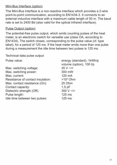
Mini-Bus Interface (option)The Mini-Bus interface is a non-reactive interface which provides a 2-wire point-to-point communication, according to EN1434-3� It connects to an external inductive interface with a maximum cable length of 50 m� The baud rate is set to 2400 Bd (also valid for the optical infrared interface)�
Pulse Output (option)The potential-free pulse output, which emits counting pulses of the heat meter, is an electronic switch for versatile use (class OA, according to EN1434)� The switch closes, corresponding to the pulse value (cf� type label), for a period of 125 ms� If the heat meter emits more than one pulse during a measurement the idle time between two pulses is 125 ms�
Technical data pulse outputPulse value: energy (standard), 1kWh/p volume (option), 100 l/pMax� switching voltage: 35 V ~/=Max� switching power: 300 mWMax� current: 120 mAResistance of contact insulation: >109 OhmMax� contact resistance (On): 25 OhmContact capacity: 1,5 pFDielectric strength (Off): 350 V ~/=Pulse length: 125 msIdle time between two pulses: 125 ms
18
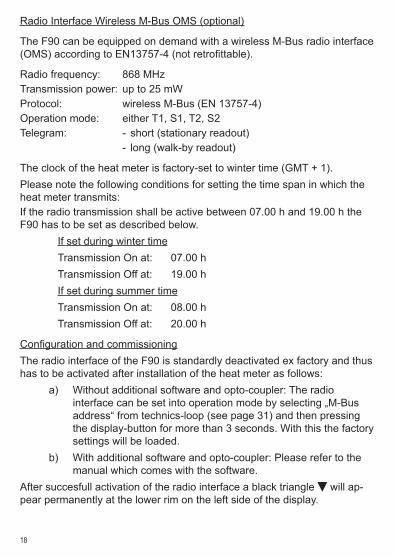
Radio Interface Wireless M-Bus OMS (optional)
The F90 can be equipped on demand with a wireless M-Bus radio interface (OMS) according to EN13757-4 (not retrofittable).
Radio frequency: 868 MHzTransmission power: up to 25 mWProtocol: wireless M-Bus (EN 13757-4)Operation mode: either T1, S1, T2, S2Telegram: - short (stationary readout) - long (walk-by readout)
The clock of the heat meter is factory-set to winter time (GMT + 1)� Please note the following conditions for setting the time span in which the heat meter transmits:If the radio transmission shall be active between 07�00 h and 19�00 h the F90 has to be set as described below� If set during winter time Transmission On at: 07�00 h Transmission Off at: 19�00 h If set during summer time Transmission On at: 08�00 h Transmission Off at: 20�00 h
Configuration and commissioningThe radio interface of the F90 is standardly deactivated ex factory and thus has to be activated after installation of the heat meter as follows:
a) Without additional software and opto-coupler: The radio interface can be set into operation mode by selecting „M-Bus address“ from technics-loop (see page 31) and then pressing the display-button for more than 3 seconds� With this the factory settings will be loaded�
b) With additional software and opto-coupler: Please refer to the manual which comes with the software�
After succesfull activation of the radio interface a black triangle will ap-pear permanently at the lower rim on the left side of the display�
19
q
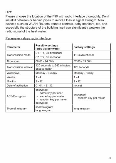
Hint:Please choose the location of the F90 with radio interface thoroughly� Don‘t install it between or behind pipes to avoid a loss in signal strength� Also devices such as WLAN-Routers, remote controls, baby monitors, etc� and especially the structure of the building itself can significantly weaken the radio signal of the heat meter�
Parameter values radio interface
Parameter Possible settings(only via software) Factory settings
Transmission modeS1 / T1, unidirectional
T1 unidirectionalS2 / T2, bidirectional
Time span 00�00 - 24�00 h 07�00 - 19�00 h
Transmission intervall 120 seconds to 240 minutes; once a month 120 seconds
Weekdays Monday - Sunday Monday - FridayWeeks 1 - 4 1 - 4Months 1 - 12 1 - 12Date of activation 01�01� - 31�12� not set
AES-Encryption
encrypted: - same key per user - same key per meter - random key per meter
decrypted
encrypted: - random key per meter
Type of telegram short telegramlong telegram long telegram
20
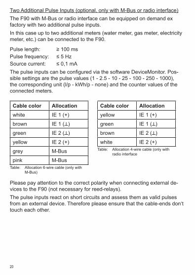
Two Additional Pulse Inputs (optional, only with M-Bus or radio interface)The F90 with M-Bus or radio interface can be equipped on demand ex factory with two additional pulse inputs�In this case up to two additional meters (water meter, gas meter, electricity meter, etc�) can be connected to the F90�
Pulse length: ≥ 100 msPulse frequency: ≤ 5 HzSource current: ≤ 0,1 mAThe pulse inputs can be configured via the software DeviceMonitor. Pos-sible settings are the pulse values (1 - 2�5 - 10 - 25 - 100 - 250 - 1000), the corresponding unit (l/p - kWh/p - none) and the counter values of the connected meters�
Please pay attention to the correct polarity when connecting external de-vices to the F90 (not necessary for reed-relays)� The pulse inputs react on short circuits and assess them as valid pulses from an external device� Therefore please ensure that the cable-ends don‘t touch each other�
Cable color Allocationwhite IE 1 (+)
brown IE 1 (┴)
green IE 2 (┴)
yellow IE 2 (+)
grey M-Bus
pink M-BusTable: Allocation 6-wire cable (only with M-Bus)
Cable color Allocationyellow IE 1 (+)
green IE 1 (┴)
brown IE 2 (┴)
white IE 2 (+)Table: Allocation 4-wire cable (only with radio interface
21
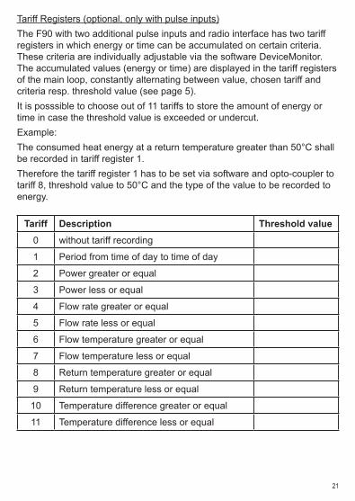
Tariff Registers (optional, only with pulse inputs)The F90 with two additional pulse inputs and radio interface has two tariff registers in which energy or time can be accumulated on certain criteria� These criteria are individually adjustable via the software DeviceMonitor� The accumulated values (energy or time) are displayed in the tariff registers of the main loop, constantly alternating between value, chosen tariff and criteria resp� threshold value (see page 5)�It is posssible to choose out of 11 tariffs to store the amount of energy or time in case the threshold value is exceeded or undercut�Example:The consumed heat energy at a return temperature greater than 50°C shall be recorded in tariff register 1�Therefore the tariff register 1 has to be set via software and opto-coupler to tariff 8, threshold value to 50°C and the type of the value to be recorded to energy�
Tariff Description Threshold value0 without tariff recording
1 Period from time of day to time of day
2 Power greater or equal
3 Power less or equal
4 Flow rate greater or equal
5 Flow rate less or equal
6 Flow temperature greater or equal
7 Flow temperature less or equal
8 Return temperature greater or equal
9 Return temperature less or equal
10 Temperature difference greater or equal
11 Temperature difference less or equal
22
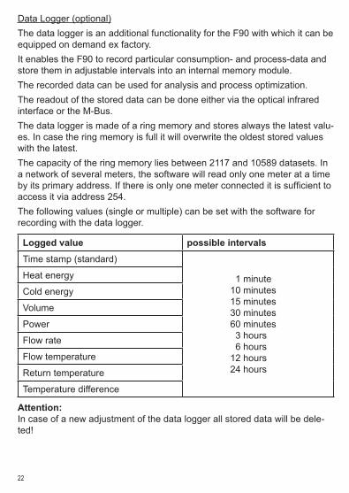
Data Logger (optional)The data logger is an additional functionality for the F90 with which it can be equipped on demand ex factory�It enables the F90 to record particular consumption- and process-data and store them in adjustable intervals into an internal memory module�The recorded data can be used for analysis and process optimization�The readout of the stored data can be done either via the optical infrared interface or the M-Bus�The data logger is made of a ring memory and stores always the latest valu-es� In case the ring memory is full it will overwrite the oldest stored values with the latest�The capacity of the ring memory lies between 2117 and 10589 datasets� In a network of several meters, the software will read only one meter at a time by its primary address. If there is only one meter connected it is sufficient to access it via address 254�The following values (single or multiple) can be set with the software for recording with the data logger�
Logged value possible intervalsTime stamp (standard)
01 minute10 minutes15 minutes30 minutes60 minutes03 hours06 hours12 hours24 hours
Heat energy
Cold energy
Volume
Power
Flow rate
Flow temperature
Return temperature
Temperature difference
Attention:In case of a new adjustment of the data logger all stored data will be dele-ted!

23
Notes
24
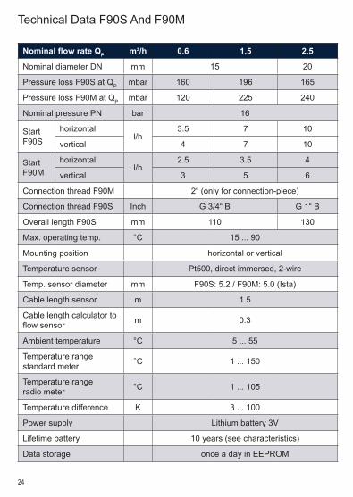
Technical Data F90S And F90M
Nominal flow rate QP m³/h 0.6 1.5 2.5
Nominal diameter DN mm 15 20
Pressure loss F90S at QP mbar 160 196 165
Pressure loss F90M at QP mbar 120 225 240
Nominal pressure PN bar 16
StartF90S
horizontall/h
3�5 7 10
vertical 4 7 10
StartF90M
horizontall/h
2�5 3�5 4
vertical 3 5 6
Connection thread F90M 2“ (only for connection-piece)
Connection thread F90S Inch G 3/4“ B G 1“ B
Overall length F90S mm 110 130
Max� operating temp� °C 15 ��� 90
Mounting position horizontal or vertical
Temperature sensor Pt500, direct immersed, 2-wire
Temp� sensor diameter mm F90S: 5�2 / F90M: 5�0 (Ista)
Cable length sensor m 1�5
Cable length calculator to flow sensor m 0�3
Ambient temperature °C 5 ��� 55
Temperature rangestandard meter °C 1 ��� 150
Temperature rangeradio meter °C 1 ��� 105
Temperature difference K 3 ��� 100
Power supply Lithium battery 3V
Lifetime battery 10 years (see characteristics)
Data storage once a day in EEPROM
25
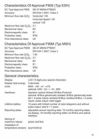
Characteristics Of Approval F90S (Typ ESH)EC Type Approval F90S: DE-07-MI004-PTB025Accuracy: EN1434-1:2007, Class 3Minimum flow rate Qi/QP: horizontal 1:50 horizontal tipped 1:25 vertical 1:25Maximum flow rate QS/QP: 2:1Mechanical class: M1Electromagnetic class: E1Protection class: IP54Flow disturbance class: U0
Characteristics Of Approval F90M (Typ MSH)EC Type Approval F90M: DE-07-MI004-PTB001Accuracy: EN1434-1:2007, Class 3Minimum flow rate Qi/QP: 1:50Maximum flow rate QS/QP: 2:1Mechanical class: M1Electromagnetic class: E1Protection class: IP54Flow disturbance class: U0
General characteristicsDisplay: LCD / 8 digits plus special charactersDisplay heat energy: 3 decimalsUnits: MWh - kW - m³ - m³/h optional: kWh - GJ - l - l/h - MWInterfaces: standard: optical infrared (M-Bus-Protocol) optional: M-Bus galvanically isolated; M-Bus galvanically isola- ted + 2 pulse inputs; wireless M-Bus; wireless M-Bus + 2 pulse inputs; pulse output; data loggerLifetime battery: 10 years with limited number of radio telegrams and without pulse output; else 6 + 1 yearsReporting dates: adjustable annual reporting date; 15 monthly reporting dates via display; 18 monthly reporting dates via M-Bus and optical interfaceStoring ofmaximum values: power and flowInstallation oftemperature sensors: asymmetrical
26
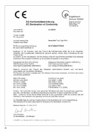
EC Declaration Of Conformity F90S (ESH)
27
EC Declaration Of Conformity F90M (MSH)

Irrtü
mer
und
Änd
erun
gen
vorb
ehal
ten,
Ver
sion
2�0
215-
en
Francaise