operation and installation manual - mts sensors€¦ · mts sensors level plus® liquid-level...
TRANSCRIPT
MTS SensorsLevel Plus® Liquid-Level Sensors - M-Series Model MC420 Analog Transmitter
Operation and Installation Manual, Document Number 550760 Revision B, 03/12 EN
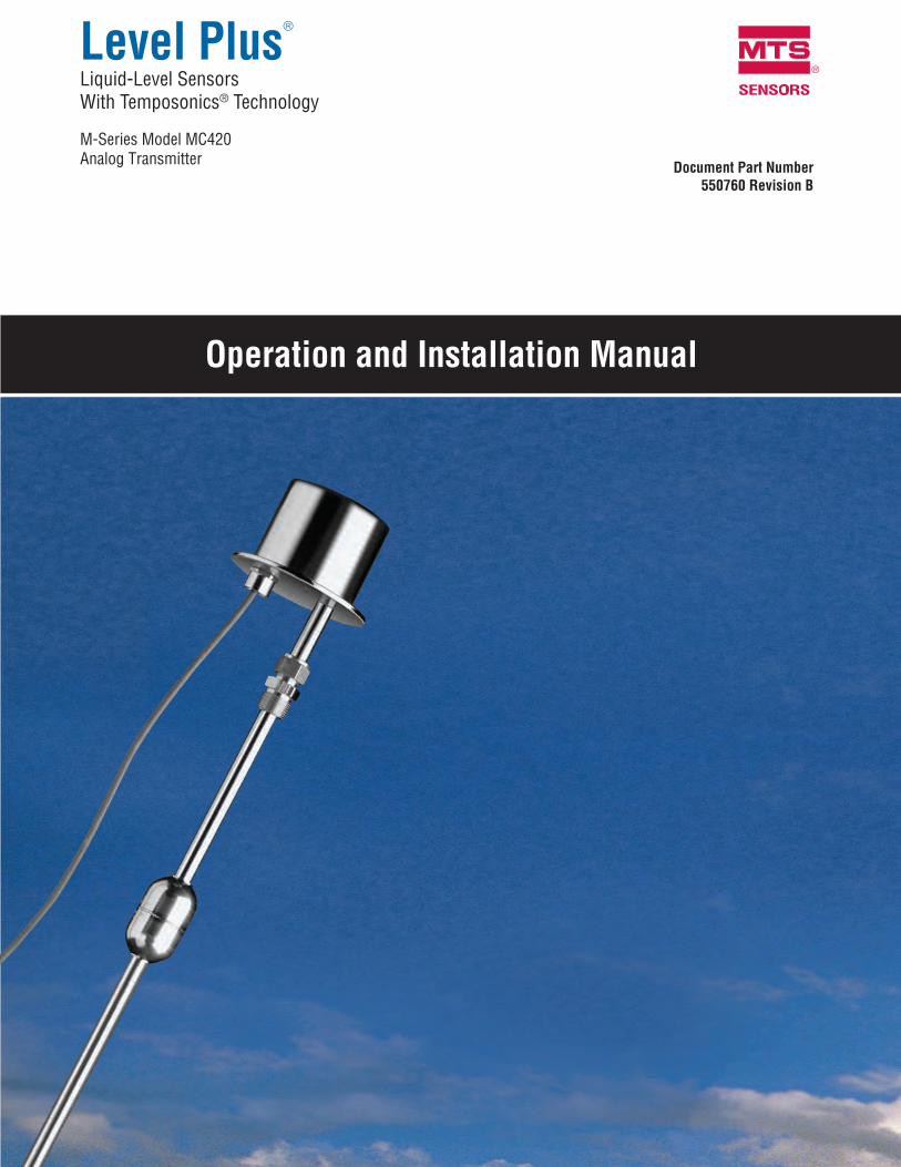
Level Plus®
Liquid-Level Sensors With Temposonics® Technology
M-Series Model MC420Analog Transmitter
SENSORS
®
Document Part Number550760 Revision B
Operation and Installation Manual

MTS SensorsLevel Plus® Liquid-Level Sensors - M-Series Model MC420 Analog Transmitter
Operation and Installation Manual, Document Number 550760 Revision B, 03/12 ENi
GeRMaNy
GeNeRal:
Tel.: +49-2351-9587-0Fax: +49-2351-56491e-mail: [email protected]://www.mtssensor.de
MaIlING aND ShIPPING aDDReSS:
MTS Sensor Technologie, GmbH & Co. KGAuf dem Schüffel 9D - 58513 Lüdenscheid, Germany
TechNIcal SuPPORT aND aPPlIcaTIONS:
Tel.: +49-2351-9587-0e-mail: [email protected]://www.mtssensor.de
JaPaN
GeNeRal:
Tel.: +81-42-775-3838Fax: +81-42-775-5516 e-mail: [email protected]://www.mtssensor.co.jp
MaIlING aND ShIPPING aDDReSS:
MTS Sensors Technology Corporation737 Aihara-cho, Machida-shiTokyo 194-0211, Japan
TechNIcal SuPPORT aND aPPlIcaTIONS:
Tel.: +81-42-775-3838Fax: +81-42-775-5512
GeNeRal:
Tel: +1-919-677-0100Fax: +1-919-677-2343E-mail: [email protected]://www.mtssensors.com
MaIlING aND ShIPPING aDDReSS:
MTS Systems CorporationSensors Division3001 Sheldon DriveCary, North Carolina, 27513, USA
cuSTOMeR SeRvIce:
Tel: +1-800-457-6620Fax: +1-800-498-4442E-mail: [email protected]
TechNIcal SuPPORT aND aPPlIcaTIONS:
24 Hour Emergency Technical SupportTel: +1-800-633-7609e-mail: [email protected]
uNITeD STaTeS
OffIce hOuRS (eST):
Monday - Thursday: 8:00 a.m. to 5:00 p.m.Friday: 8:00 a.m. to 4:00 p.m.
ReMITTaNce aDDReSS:
MTS Systems CorporationSensors DivisionNW 5872 P.O. Box 1450Minneapolis, MN, 55486-5872
QuOTe aND cONTRacT TeRMS & cONDITIONS:
The parties expressly agree that the purchase and use of Material and/or Services from MTS Sensors Division are subject to MTS’ Terms and Conditions, in effect as of the date of this document, which are located at http://www.mtssensors.com/fileadmin/media/pdfs/Terms_and_conditions.pdf and are incorporated by reference into this and any ensuing contract. Printed Terms and Conditions can be provided upon request by emailing [email protected] or if you prefer, go to http://www.mtssensors.com/index and click the Quote/Contract Terms and Conditions link at the bottom of the page to download the PDF.
cont
act
Info
rmat
ion
Model Mc420 Operation and Installation Manualcontact Information
MTS SensorsLevel Plus® Liquid-Level Sensors - M-Series Model MC420 Analog Transmitter Operation and Installation Manual, Document Number 550760 Revision B, 03/12 EN ii
Refe
renc
e In
form
atio
nModel Mc420 Operation and Installation ManualReference Information
Notices used in this manual
This manual contains notices to highlight specific information as follows:
Notes:
These notices provide important tips, guidance, or advice.
Important:
These notices provide information that might help you avoid inconvenient or problem situations.
attention:
These notices indicate possible damage to programs, devices, or data and is placed justbefore the instruction or situation in which damage could occur.
caution:
These notices indicate situations that can be potentially hazardous to you. A Caution notice is placed justbefore a description of a potentially hazardous procedure, step, or situation.
Related publications
The following publications are listed below by part number followed by description and are avail-able in Adobe Acrobat Portable Document Format (PDF) at http://www.mtssensors.com/
550752 - Product Specification, Model MC420 Analog Transmitter551103 - Level Plus Accessories Catalog
For information about safe work procedures, refer to the following documentation:National Electric Code ANSI/NFPA 70CSA C22.1 Canadian Electrical Code
how this manual is organized
“Introduction”, provides an overview of the manual. “Terms and Definitions”, provides definitions of terms used in this manual.“Product Overview”, gives an overall product description for the Level Plus liquid-level transmitter, its specifications, use, output, and electronics.“Installation and Mounting”, provides detailed installation and mounting information.“Electrical Connections and Wiring Procedures”, provides engineering specifications and wiring diagrams to assist in the installation process.“Maintenance and Field Service”, provides guidelines for general maintenance.“Troubleshooting”, provides a list of symptoms, their possible cause and the action to be taken when troubleshooting the transmitter.Setup using magnet - provides procedures for setting 4 and 20 mA set points using supplied magnet.Setup using HART® Field Communicator - provides procedures for setting 4 and 20 mA set pointsSetup using MTS Field Setup Software - provides software installation, parameter setup, and calibration procedures.“Agency Information” provides comprehensive listings of agency approvals and stan-dards, installation drawings, labels and applicable protocols.
Getting information, help, and service
You can get the latest ordering information and software updates by visiting www.mtssensors.com websiteGeneral contact information, shipping and office hours are available on page i.
MTS SensorsLevel Plus® Liquid-Level Sensors - M-Series Model MC420 Analog Transmitter
Operation and Installation Manual, Document Number 550760 Revision B, 03/12 ENiii
Tabl
e of
cont
ents
Model Mc420 Operation and Installation ManualTable of contents
contact informationGeneral ........................................................................................ iMailing and shipping address ..................................................... iCustomer service ........................................................................ iTechnical support and applications ............................................. iOffice hours ................................................................................ iRemittance address .................................................................... iQuote and contract terms and conditions .................................... i
Reference informationNotices used in this manual ........................................................ iiRelated publications .................................................................... iiHow this manual is organized ..................................................... iiGetting information, help, and service ........................................ ii
IntroductionIntroduction ............................................................... 1Public website support portal ......................................... 1
Terms and definitionsTerms and definitions reference ...................................... 2
Product overviewProduct overview ........................................................ 3
Industries .................................................................................... 3 Applications ................................................................................ 3 Features ...................................................................................... 3
components .............................................................. 3Housing ...................................................................................... 3Outer pipe configuration ............................................................ 4Floats ......................................................................................... 4Internal electronics ...................................................................... 4Accessories ................................................................................ 4
Theory of operation ...................................................... 5accuracy ................................................................. 5Warranty ................................................................. 5Model number identification ........................................... 6Product specifications .................................................. 7
Installation and mountingInstallation and Mounting ............................................. 8Storage ................................................................... 8Stilling wells and guide poles ........................................ 8Installation................................................................ 8Mounting ................................................................. 9
electrical connectionselectrical connections and wiring procedures ..................... 10Safety recommendations for installation ........................... 10Recommended cable types ........................................... 11
Cable specifications ................................................................. 11Grounding ............................................................... 12Safety barriers for IS installation .................................... 12
Maintenance and field serviceMaintenance and field service ....................................... 13General maintenance and field service requirements ........... 13
Float maintenance .................................................................... 13Field service ............................................................................. 13Service / RMA policy ................................................................ 13
TroubleshootingTroubleshooting procedures ......................................... 13
SetupQuick set-up procedure ................................................ 14
Tools needed ............................................................................ 14Setup using supplied magnet ........................................ 14
To set to Zero ........................................................................... 14To set Span .............................................................................. 14
Setup using haRT field communicator ............................. 15Preparing the transmitter for re-calibration .............................. 15Setting the low value ............................................................... 15Setting the upper range value ................................................. 16
Setup using MTS field Setup software ............................. 16Using the MTS Field Setup software ........................................ 16Advanced setup tab ................................................................. 17Calibration tab ......................................................................... 18Output tab ............................................................................... 18
agency informationagency approvals ...................................................... 19
FM/CSA and ATEX .................................................................... 19 Installation drawing ............................................................. 20Notes ................................................................................... 22Wiring and connections ....................................................... 23Labels ................................................................................... 24
agency certifications ................................................. 26ATEX ......................................................................................... 26CSA .... ...................................................................................... 30FM ........................................................................................... 32

MTS SensorsLevel Plus® Liquid-Level Sensors - M-Series Model MC420 Analog Transmitter Operation and Installation Manual, Document Number 550760 Revision B, 03/12 EN
Introduction
MTS is recognized as the pioneer, innovator and leader in magnetostrictive sensing. The new Level Plus® M-Series transmitter design repre-sents a continuation of our on-going effort to provide effective, innovative and reliable products to the Liquid Level marketplace.
This manual will provide the following information about the Level Plus Model MC420 analog transmitter:
• Terms and definitions• Product overview• Installation and mounting• Electrical connections• Maintenance and field service• Troubleshooting• Quick start-up guide• Setup using the supplied magnet• Setup using a HART® Field Communicator• Setup using MTS Field Setup Software• Agency information• Product certifications
Public website support portal
Visit our support portal at http://www.mtssensors.com for:
• Building Level Plus M-Series Model MC420 analog transmitter model numbers• Latest documentation releases• Detailed ordering information• Latest software updates
Model Mc420 Operation and Installation ManualIntroduction
Intro
duct
ion
1
MTS SensorsLevel Plus® Liquid-Level Sensors - M-Series Model MC420 Analog Transmitter
Operation and Installation Manual, Document Number 550760 Revision B, 03/12 EN2
Terms and definitions reference
h
HART® – a Bidirectional communication protocol that provides data access between intelligent field instruments and host systems.
I
Interface – Noun; The measurement of the level of one liquid when that liquid is below another liquid.
Interface – Adj.; The Software Graphical User Interface (GUI) that allows the user to access software protocols (HART).
Intrinsic safety – ‘Intrinsically safe’ - Type of protection based on the restriction of electrical energy within apparatus of interconnecting wiring exposed to potentially explosive atmosphere to a level below that which can cause ignition by either sparking or heating effects.
N
NeMa Type 4X – A product Enclosure intended for indoor or outdoor use primarily to provide a degree of protection against corrosion, windblown dust and rain, splashing water, and hose-directed water; and to be undamaged by the formation of ice on the enclosure. They are not intended to provide protection against conditions such as internal condensation or internal icing.
NPT – U.S. standard defining tapered pipe threads used to join pipes and fittings.
S
Specific Gravity – The density ratio of a liquid to the density of water at the same conditions. Te
rms
and
Defin
ition
s
Model Mc420 Operation and Installation ManualTerms and Definitions
MTS SensorsLevel Plus® Liquid-Level Sensors - M-Series Model MC420 Analog Transmitter Operation and Installation Manual, Document Number 550760 Revision B, 03/12 EN 3
Product Overview
The Level Plus Model MC420 Liquid-Level transmitter is a continuous multi-functional magnetostrictive transmitter that provides product level or interface level to the user via 4 to 20 mA current loop or HART. Magnetostrictive technology is one of the most accurate and repeatable level technologies available to date. MTS is the inventor and purveyor of magnetostrictive technology and has been serving the level industry for over 30 years.
INDuSTRIeS aPPlIcaTIONS feaTuReS
� Petrochemical � chemical � Water and Wastewater
� General Process � Industrial chemicals � Solvents � Detergents and Soaps � lubricating Oils
� 4 to 20 ma Output with haRT®
� Single channel Output � level Measurements
• Product • Interface
� No Scheduled Maintenance or Recalibration � high accuracy and Repeatability � Intrinsically Safe (I.S.)
components
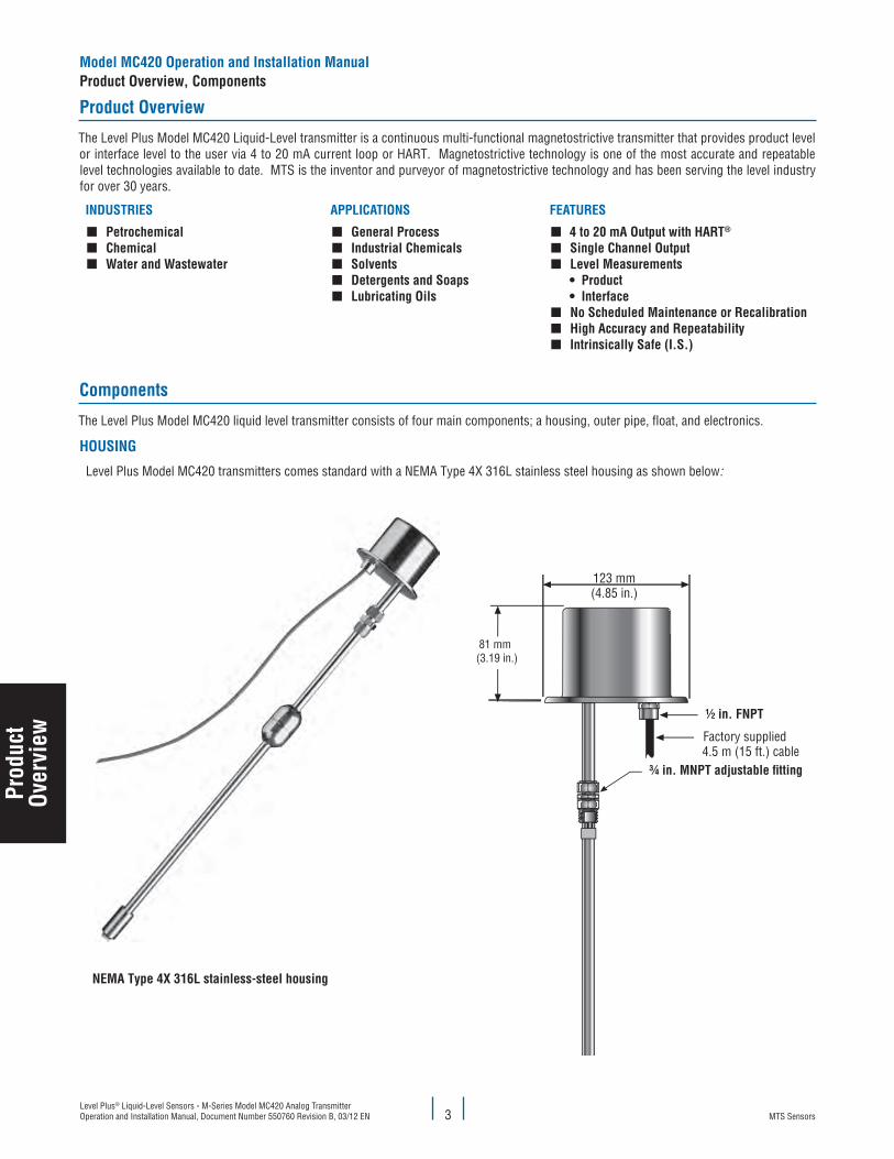
The Level Plus Model MC420 liquid level transmitter consists of four main components; a housing, outer pipe, float, and electronics.
hOuSING
Level Plus Model MC420 transmitters comes standard with a NEMA Type 4X 316L stainless steel housing as shown below:
NeMa Type 4X 316l stainless-steel housing
¾ in. MNPT adjustable tting
Prod
uct
Over
view
Model Mc420 Operation and Installation ManualProduct Overview, components
MTS SensorsLevel Plus® Liquid-Level Sensors - M-Series Model MC420 Analog Transmitter
Operation and Installation Manual, Document Number 550760 Revision B, 03/12 EN4
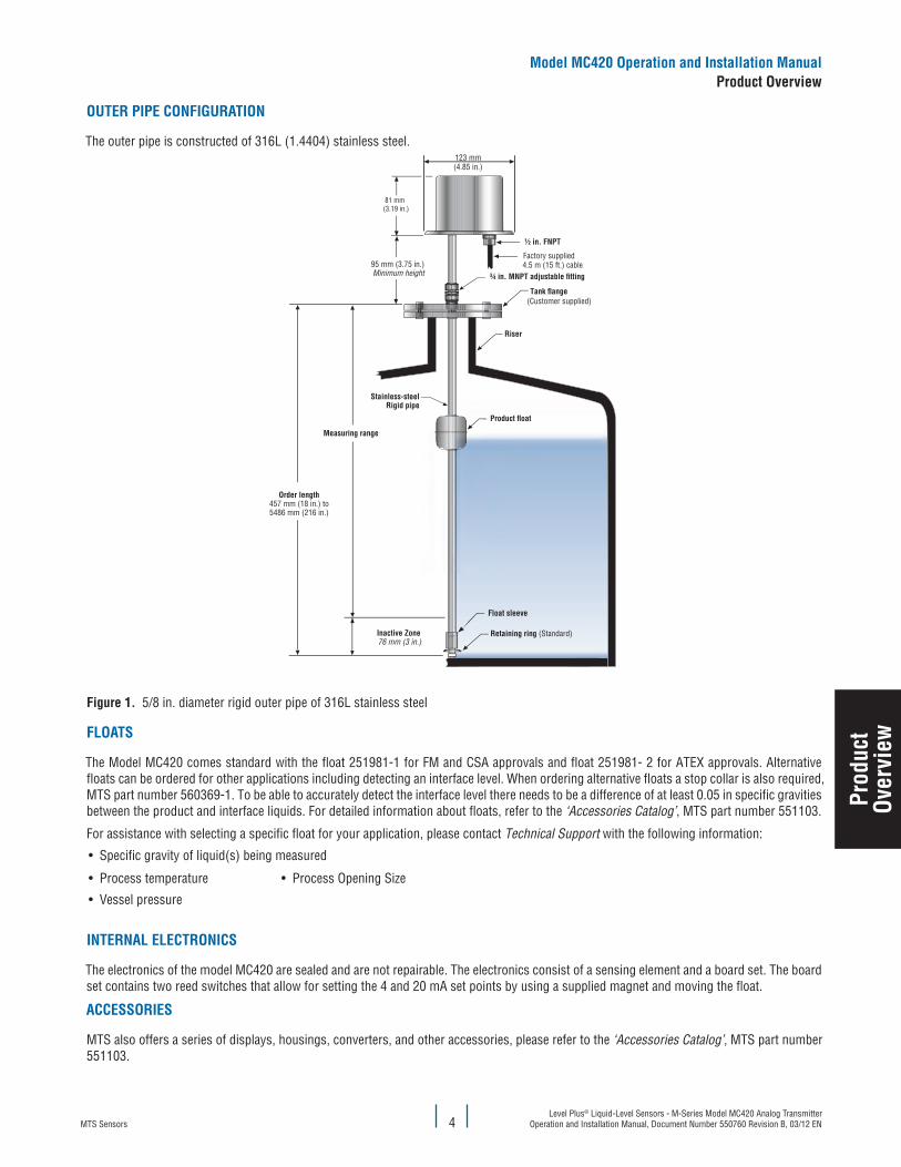
OuTeR PIPe cONfIGuRaTION
The outer pipe is constructed of 316L (1.4404) stainless steel.
¾ in. MNPT adjustable tting
figure 1. 5/8 in. diameter rigid outer pipe of 316L stainless steel
flOaTS
The Model MC420 comes standard with the float 251981-1 for FM and CSA approvals and float 251981- 2 for ATEX approvals. Alternative floats can be ordered for other applications including detecting an interface level. When ordering alternative floats a stop collar is also required, MTS part number 560369-1. To be able to accurately detect the interface level there needs to be a difference of at least 0.05 in specific gravities between the product and interface liquids. For detailed information about floats, refer to the ‘Accessories Catalog’, MTS part number 551103.
For assistance with selecting a specific float for your application, please contact Technical Support with the following information:
• Specific gravity of liquid(s) being measured
• Process temperature • Process Opening Size
• Vessel pressure
INTeRNal elecTRONIcS
The electronics of the model MC420 are sealed and are not repairable. The electronics consist of a sensing element and a board set. The board set contains two reed switches that allow for setting the 4 and 20 mA set points by using a supplied magnet and moving the float.
acceSSORIeS
MTS also offers a series of displays, housings, converters, and other accessories, please refer to the ‘Accessories Catalog’, MTS part number 551103.
Model Mc420 Operation and Installation ManualProduct Overview
Prod
uct
Over
view
MTS SensorsLevel Plus® Liquid-Level Sensors - M-Series Model MC420 Analog Transmitter Operation and Installation Manual, Document Number 550760 Revision B, 03/12 EN 5
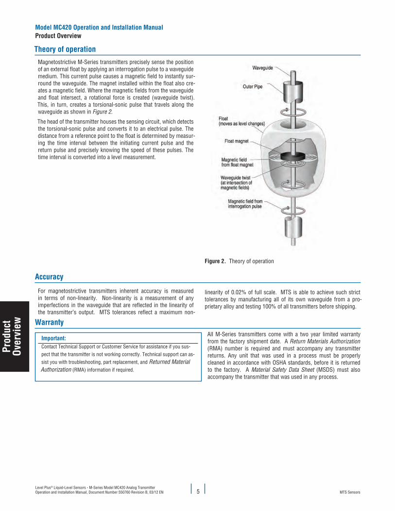
figure 2. Theory of operation
accuracy
For magnetostrictive transmitters inherent accuracy is measured in terms of non-linearity. Non-linearity is a measurement of any imperfections in the waveguide that are reflected in the linearity of the transmitter’s output. MTS tolerances reflect a maximum non-
linearity of 0.02% of full scale. MTS is able to achieve such strict tolerances by manufacturing all of its own waveguide from a pro-prietary alloy and testing 100% of all transmitters before shipping.
Warranty
Magnetostrictive M-Series transmitters precisely sense the position of an external float by applying an interrogation pulse to a waveguide medium. This current pulse causes a magnetic field to instantly sur-round the waveguide. The magnet installed within the float also cre-ates a magnetic field. Where the magnetic fields from the waveguide and float intersect, a rotational force is created (waveguide twist). This, in turn, creates a torsional-sonic pulse that travels along the waveguide as shown in Figure 2.
The head of the transmitter houses the sensing circuit, which detects the torsional-sonic pulse and converts it to an electrical pulse. The distance from a reference point to the float is determined by measur-ing the time interval between the initiating current pulse and the return pulse and precisely knowing the speed of these pulses. The time interval is converted into a level measurement.
Theory of operation
Important: Contact Technical Support or Customer Service for assistance if you sus-pect that the transmitter is not working correctly. Technical support can as-sist you with troubleshooting, part replacement, and Returned Material Authorization (RMA) information if required.
All M-Series transmitters come with a two year limited warranty from the factory shipment date. A Return Materials Authorization (RMA) number is required and must accompany any transmitter returns. Any unit that was used in a process must be properly cleaned in accordance with OSHA standards, before it is returned to the factory. A Material Safety Data Sheet (MSDS) must also accompany the transmitter that was used in any process.
Model Mc420 Operation and Installation ManualProduct Overview
Prod
uct
Over
view
MTS SensorsLevel Plus® Liquid-Level Sensors - M-Series Model MC420 Analog Transmitter
Operation and Installation Manual, Document Number 550760 Revision B, 03/12 EN
Model Mc420 Operation and Installation ManualProduct Overview
6
Model number identification
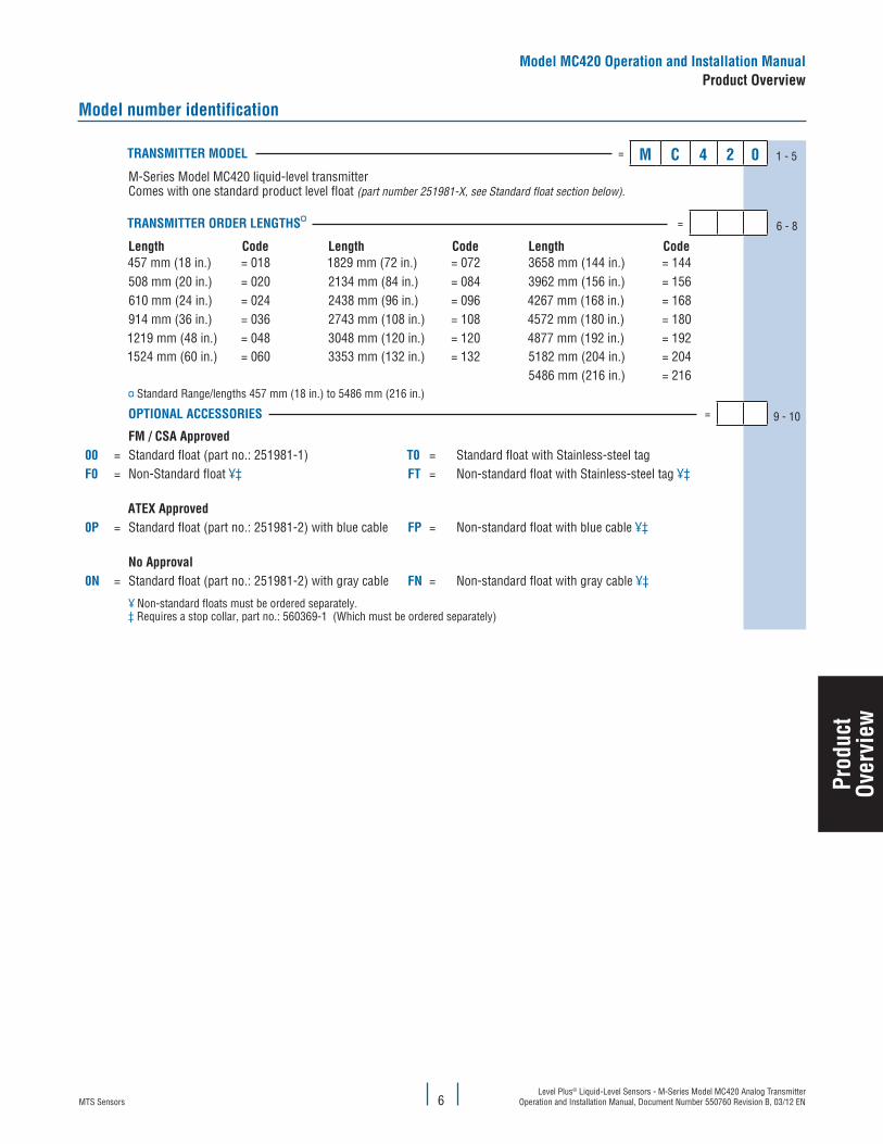
TRaNSMITTeR MODel = M c 4 2 0 1 - 5
M-Series Model MC420 liquid-level transmitter Comes with one standard product level float (part number 251981-X, see Standard float section below).
TRaNSMITTeR ORDeR leNGThS¤ = 6 - 8
length code length code length code457 mm (18 in.) = 018 1829 mm (72 in.) = 072 3658 mm (144 in.) = 144508 mm (20 in.) = 020 2134 mm (84 in.) = 084 3962 mm (156 in.) = 156610 mm (24 in.) = 024 2438 mm (96 in.) = 096 4267 mm (168 in.) = 168914 mm (36 in.) = 036 2743 mm (108 in.) = 108 4572 mm (180 in.) = 1801219 mm (48 in.) = 048 3048 mm (120 in.) = 120 4877 mm (192 in.) = 1921524 mm (60 in.) = 060 3353 mm (132 in.) = 132 5182 mm (204 in.) = 204
5486 mm (216 in.) = 216¤ Standard Range/lengths 457 mm (18 in.) to 5486 mm (216 in.)
OPTIONal acceSSORIeS = 9 - 10
fM / cSa approved00 = Standard float (part no.: 251981-1) T0 = Standard float with Stainless-steel tagf0 = Non-Standard float ¥‡ fT = Non-standard float with Stainless-steel tag ¥‡
aTeX approved0P = Standard float (part no.: 251981-2) with blue cable fP = Non-standard float with blue cable ¥‡
No approval0N = Standard float (part no.: 251981-2) with gray cable fN = Non-standard float with gray cable ¥‡
¥ Non-standard floats must be ordered separately.‡ Requires a stop collar, part no.: 560369-1 (Which must be ordered separately)
Prod
uct
Over
view
MTS SensorsLevel Plus® Liquid-Level Sensors - M-Series Model MC420 Analog Transmitter Operation and Installation Manual, Document Number 550760 Revision B, 03/12 EN 7
Model Mc420 Operation and Installation ManualProduct Overview
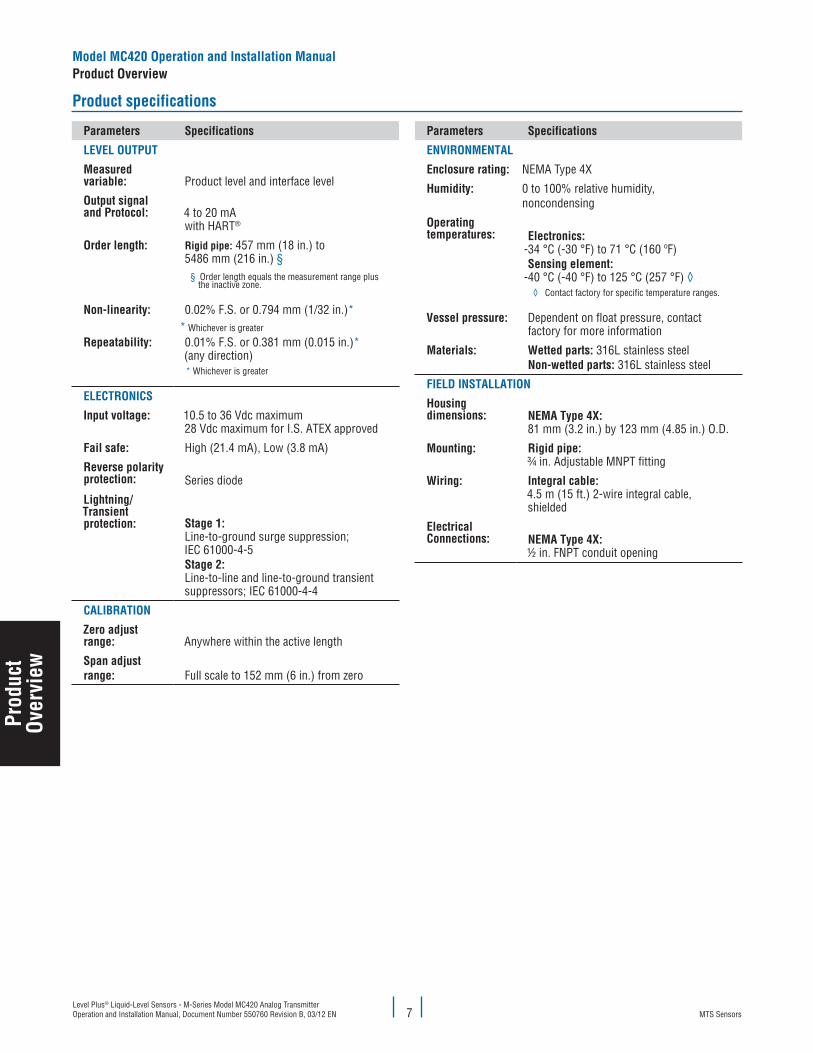
Product specifications
Parameters Specifications
level OuTPuT
Measured variable: Product level and interface level
Output signal and Protocol: 4 to 20 mA
with HART®
Order length: Rigid pipe: 457 mm (18 in.) to 5486 mm (216 in.) §
§ Order length equals the measurement range plus the inactive zone.
Non-linearity: 0.02% F.S. or 0.794 mm (1/32 in.)** Whichever is greater
Repeatability: 0.01% F.S. or 0.381 mm (0.015 in.)*(any direction) * Whichever is greater
elecTRONIcS
Input voltage: 10.5 to 36 Vdc maximum28 Vdc maximum for I.S. ATEX approved
fail safe: High (21.4 mA), Low (3.8 mA)
Reverse polarity protection: Series diode
lightning/Transient protection: Stage 1:
Line-to-ground surge suppression; IEC 61000-4-5Stage 2: Line-to-line and line-to-ground transient suppressors; IEC 61000-4-4
calIBRaTION
Zero adjust range: Anywhere within the active length
Span adjust range: Full scale to 152 mm (6 in.) from zero
Parameters Specifications
eNvIRONMeNTal
enclosure rating: NEMA Type 4X
humidity: 0 to 100% relative humidity, noncondensing
Operating temperatures: electronics:
-34 °C (-30 °F) to 71 °C (160 ºF) Sensing element:
-40 °C (-40 °F) to 125 °C (257 °F) ◊◊ Contact factory for specific temperature ranges.
vessel pressure: Dependent on float pressure, contact factory for more information
Materials: Wetted parts: 316L stainless steelNon-wetted parts: 316L stainless steel
fIelD INSTallaTION
housing dimensions: NeMa Type 4X:
81 mm (3.2 in.) by 123 mm (4.85 in.) O.D.
Mounting: Rigid pipe:¾ in. Adjustable MNPT fitting
Wiring: Integral cable:4.5 m (15 ft.) 2-wire integral cable, shielded
electrical connections: NeMa Type 4X:
½ in. FNPT conduit opening
Prod
uct
Over
view
MTS SensorsLevel Plus® Liquid-Level Sensors - M-Series Model MC420 Analog Transmitter
Operation and Installation Manual, Document Number 550760 Revision B, 03/12 EN8
Installation and mounting
This section contains information about storing your transmitter (prior to installation) and detailed procedures for installing and mounting your transmitter.
Storage
If storage is required prior to installation, store indoors in a dry environment at ambient temperature range not exceeding -40 °C (-40 °F) to 71 °C (160 °F).
Stilling wells and guide poles
Level Plus transmitters can be mounted in slotted or unslotted stilling wells but a slotted stilling well is always preferred. Using a unslotted stilling well will negatively affect performance of any level device as the level in the stilling well can differ from the level in the tank. The Level Plus transmitter can also be installed to one side of the stilling well to also allow for sampling and manual gauging from the same opening as the automatic tank gauging. Contact Technical Support for details.
Level Plus transmitters do not require a stilling well for installation. Our transmitters are installed in numerous tanks without stilling wells with no loss in performance due to our patented flexible waveguide and hose. A stilling well is highly recommended for agitated, turbulent, and/or fast filling tanks.
Installation
The installation procedures below are illustrated using the adjustable NPT fitting for a threaded flange mount.
RIGID PROBe
Tools Required:
• Channel lock pliers• Common screwdriver
caution:
It is recommended that assembly and mounting of this transmitter should not be performed alone. To ensure proper and safe assembly of the M-Series transmitter, a minimum of two (2) individuals are recommended. Gloves are also recommended. In addition , PPE is required for work areas such as safety shoes, safety glasses, hard hat, and fire resistant clothing.
Perform the following steps to Install the Model MC420 transmitter:
1. Remove the float sleeve and E-ring. With assistance, feed the rigid pipe through the hole of the removed tank flange until the flange is positioned near the top of the transmitter. Insert the threaded portion of the adjustable fitting into the customer supplied flange and tighten (apply pipe thread sealant if required). Be careful not to drop the flange as it can damage the transmitter.
2. Slide the float onto the rigid pipe. Install float sleeve and E-ring. Do not drop the float or allow it to free fall along the rigid pipe as damage may result.
Note:
The stop collar can be removed or adjusted based on the float selected for the application. Please consult the factory for more information.
3. Slide float back down to the float sleeve to prevent it from free falling during installation into the tank. Insert the rigid pipe (with float) through the tank opening and lower the transmitter/float assembly into the tank until it rests on the bottom. DO NOT DROP OR DAMAGE THE PIPE.4. Secure the flange onto the tank mount.5. Pull the transmitter upward so the end plug is just resting on the floor of the tank. Tighten the adjustable fitting to hold the transmitter
in place.6. Terminate the field wire cables noting proper wire orientation.
Model Mc420 Operation and Installation ManualInstallation and Mounting
Inst
alla
tion
&
Mou
ntin
g
MTS SensorsLevel Plus® Liquid-Level Sensors - M-Series Model MC420 Analog Transmitter Operation and Installation Manual, Document Number 550760 Revision B, 03/12 EN 9
Mounting
The method of mounting the transmitter is dependent on the vessel or tank in which it is being used.
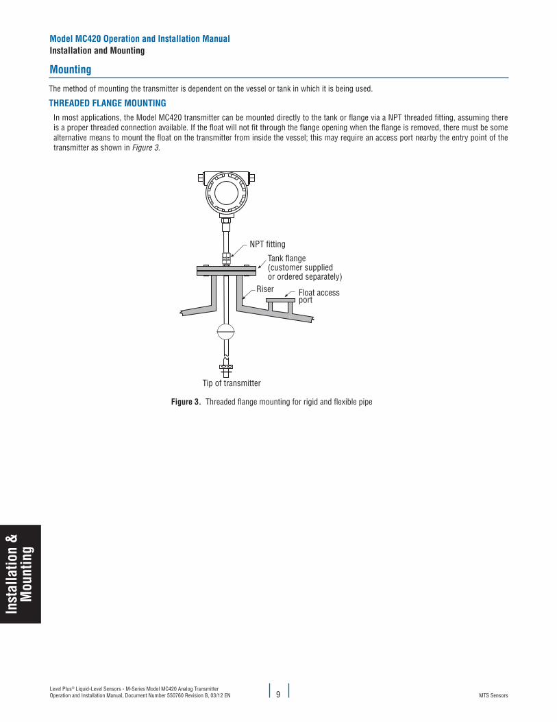
ThReaDeD flaNGe MOuNTINGIn most applications, the Model MC420 transmitter can be mounted directly to the tank or flange via a NPT threaded fitting, assuming there is a proper threaded connection available. If the float will not fit through the flange opening when the flange is removed, there must be some alternative means to mount the float on the transmitter from inside the vessel; this may require an access port nearby the entry point of the transmitter as shown in Figure 3.
Model Mc420 Operation and Installation ManualInstallation and Mounting
Inst
alla
tion
&M
ount
ing
Riser
NPT fitting
Tank flange(customer suppliedor ordered separately)
Float accessport
Tip of transmitter
figure 3. Threaded flange mounting for rigid and flexible pipe
MTS SensorsLevel Plus® Liquid-Level Sensors - M-Series Model MC420 Analog Transmitter
Operation and Installation Manual, Document Number 550760 Revision B, 03/12 EN10
electrical connections and wiring procedures
A typical intrinsically safe connection for the Level Plus Model MC420 transmitter includes protective safety barriers, a power supply and a reading or monitoring device. Refer to Agency information for detailed information.
Safety recommendations for installation
Be sure to:
1. Always follow applicable local and national electrical codes and observe polarity when making electrical connections. 2. Never make electrical connections to the M-Series transmitter with power turned on. 3. Make sure that no wire strands are loose or sticking out of the terminal block connection which could short and cause a problem. 4. Make sure that no wire strands, including shield, are in contact with the electronic module enclosure. 5. The electronics module enclosure is grounded through internal circuitry and is electronically isolated from the explosion-proof housing.
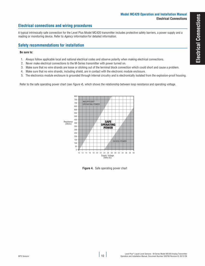
Refer to the safe operating power chart (see Figure 4), which shows the relationship between loop resistance and operating voltage.
Model Mc420 Operation and Installation Manualelectrical connections
elec
trica
l con
nect
ions
800
750
700
650
600
550
500
450
400
350
300
250
200
150
100
50
0
10 12 14 16 18 20 22 24 26 28 30 32 34 36 38 40
INSUFFICIENTOPERATING POWER
EXCESS POWER
Resistance(Ohms)
Supply Voltage (Volts DC)
figure 4. Safe operating power chart
MTS SensorsLevel Plus® Liquid-Level Sensors - M-Series Model MC420 Analog Transmitter Operation and Installation Manual, Document Number 550760 Revision B, 03/12 EN 11
Recommended cable types
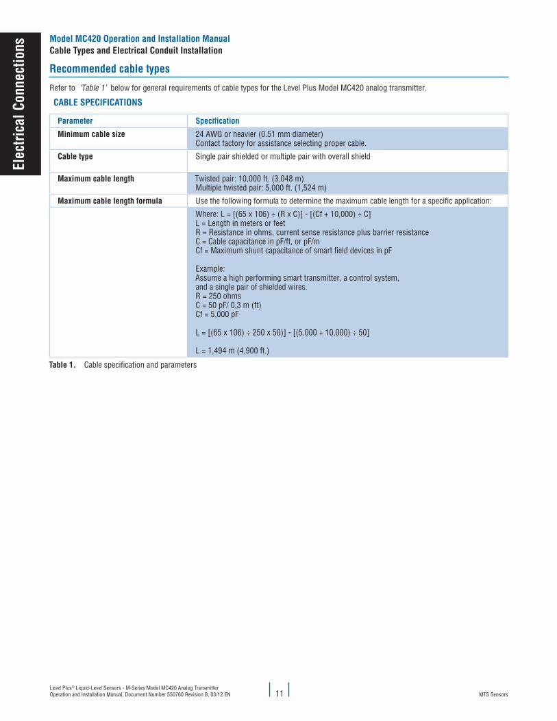
Refer to ‘Table 1’ below for general requirements of cable types for the Level Plus Model MC420 analog transmitter.
caBle SPecIfIcaTIONS
Parameter Specification
Minimum cable size 24 AWG or heavier (0.51 mm diameter)Contact factory for assistance selecting proper cable.
cable type Single pair shielded or multiple pair with overall shield
Maximum cable length Twisted pair: 10,000 ft. (3,048 m)Multiple twisted pair: 5,000 ft. (1,524 m)
Maximum cable length formula Use the following formula to determine the maximum cable length for a specific application:
Where: L = [(65 x 106) ÷ (R x C)] - [(Cf + 10,000) ÷ C]L = Length in meters or feetR = Resistance in ohms, current sense resistance plus barrier resistanceC = Cable capacitance in pF/ft, or pF/mCf = Maximum shunt capacitance of smart field devices in pF
Example:Assume a high performing smart transmitter, a control system,and a single pair of shielded wires.R = 250 ohmsC = 50 pF/ 0,3 m (ft)Cf = 5,000 pF
L = [(65 x 106) ÷ 250 x 50)] - [(5,000 + 10,000) ÷ 50]
L = 1,494 m (4,900 ft.)
Table 1. Cable specification and parameters
Model Mc420 Operation and Installation Manualcable Types and electrical conduit Installation
elec
trica
l con
nect
ions
MTS SensorsLevel Plus® Liquid-Level Sensors - M-Series Model MC420 Analog Transmitter
Operation and Installation Manual, Document Number 550760 Revision B, 03/12 EN12
Grounding
Note:
Grounding the transmitter through a threaded conduit connection does not provide sufficient ground.
The earth ground for the internal electronics is connected to the housing and the drain wire of the integral cable. The drain wire should be connected to an earth ground for maximum surge protection.
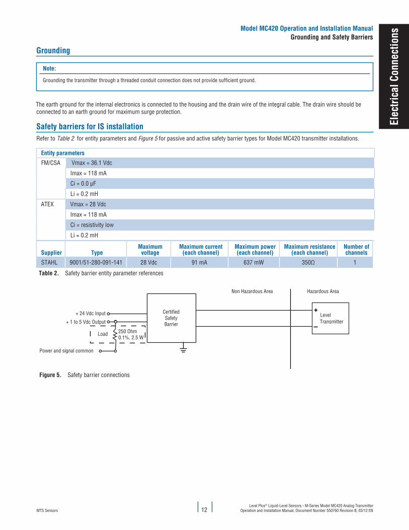
Safety barriers for IS installationRefer to Table 2 for entity parameters and Figure 5 for passive and active safety barrier types for Model MC420 transmitter installations.
entity parameters
FM/CSA Vmax = 36.1 Vdc
Imax = 118 mA
Ci = 0.0 µF
Li = 0.2 mH
ATEX Vmax = 28 Vdc
Imax = 118 mA
Ci = resistivity low
Li = 0.2 mH
Supplier TypeMaximum
voltageMaximum current
(each channel)Maximum power(each channel)
Maximum resistance(each channel)
Number of channels
STAHL 9001/51-280-091-141 28 Vdc 91 mA 637 mW 350Ω 1
Table 2. Safety barrier entity parameter references
figure 5. Safety barrier connections
Non Hazardous Area Hazardous Area
CertifiedSafetyBarrier
+ 24 Vdc Input LevelTransmitter
Non Hazardous Area Hazardous Area
CertifiedSafety Bariers
24 VdcSupply-Voltage
I (A)
4-20mA
I (A)
4-20mA
24 VdcSupply-Voltage
I.S. Ground connection
CertifiedSafety Bariers
I.S. Ground connection
Transmitter 1
Transmitter 2
+ 1 to 5 Vdc Output
Load 250 Ohm0.1%, 2.5 W
Power and signal common
Model Mc420 Operation and Installation ManualGrounding and Safety Barriers
elec
trica
l con
nect
ions
MTS SensorsLevel Plus® Liquid-Level Sensors - M-Series Model MC420 Analog Transmitter Operation and Installation Manual, Document Number 550760 Revision B, 03/12 EN 13
Mai
nten
ance
& f
ield
Ser
vice
Maintenance and field service
This section contains information about post installation maintenance and provides an overview of MTS Sensors’ repair and replacement procedures.
General maintenance and field service requirements
Notes:
Please contact Technical Support or Customer Service for help when damage occurs in order to obtain a return materials authorization (RMA) number. Packages without a RMA number may be rejected. Any unit that was used in a process must be properly cleaned in accordance with OSHA standards, before it is returned to the factory. A Material Safety Data Sheet (MSDS) must accompany material that was used in any media.
flOaT MaINTeNaNce
Level Plus M-Series transmitters use magnetostrictive technology and only have one moving part—the float. This technology ensures no scheduled maintenance or recalibration is required. However, MTS recommends that you check the transmitter pipe annually for build up of process material. Floats should move freely along the pipe. If they do not, routine cleaning should be performed.
fIelD SeRvIce
The Model MC420 transmitter is not repairable. Troubleshooting may be performed but if there is any damage to the MC420 transmitter a new one must be ordered.
SeRvIce / RMa POlIcy
If the customer suspects their transmitter is damaged or not functioning correctly, call MTS Technical Support for further instruction. If it is necessary to return the transmitter to the factory, an RMA number is required and can only be issued by Technical Support. Product returns that do not include an RMA will be returned to the customer. MTS evaluates the transmitter and advises the customer whether a repair or replacement is necessary and any cost that might be incurred. If the customer declines repair/replacement or the transmitter has no fault found, the unit is sent back as is and the customer is charged with a standard evaluation fee.
If the transmitter is under warranty and a manufacturer’s defect is detected, there will be no cost to the customer for repair or replacement. If the transmitter is out of warranty or if the customer has damaged the transmitter, a repair or replacement quote will be provided. In specific cases where the transmitter can not be removed and returned to the factory for evaluation, field evaluations can be performed in the field by an MTS technician. If field evaluation must be performed, the customer is responsible for all expenses incurred for travel, evaluation, parts and repair time. However, if the transmitter is under warranty and the problem is due to a manufacturer’s defect, there is no cost to the customer for replacement parts. To discuss all service options, contact Technical Support.
Troubleshooting
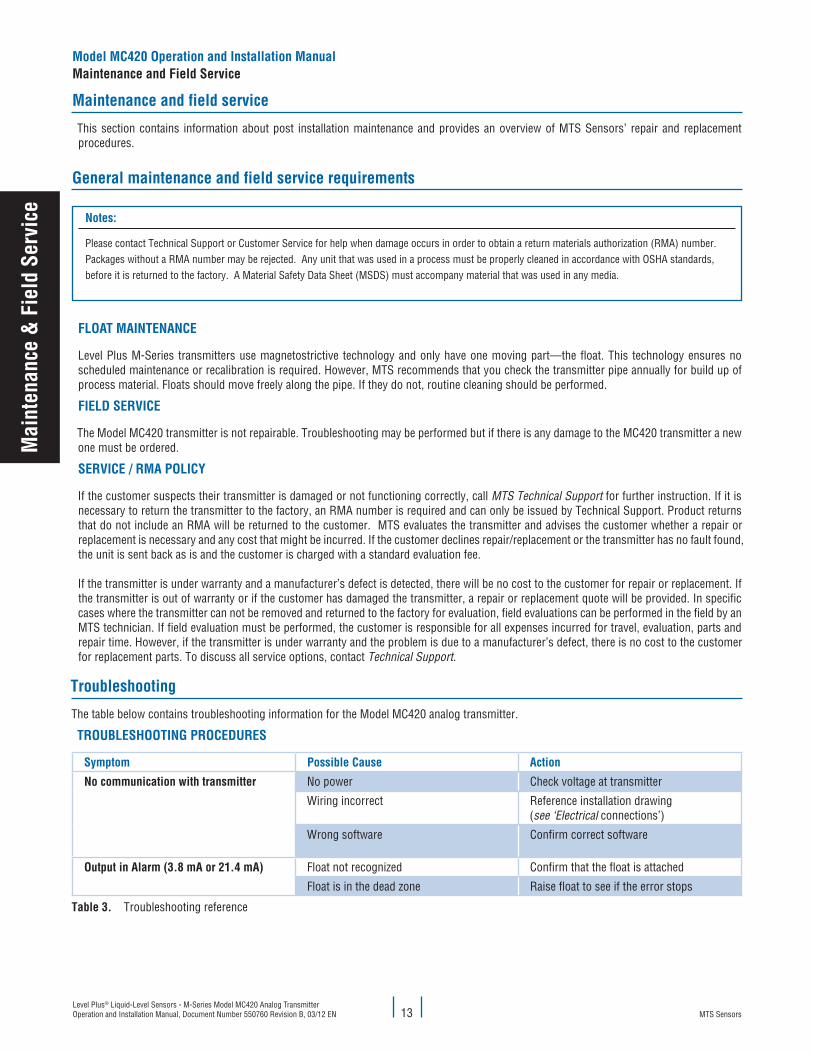
The table below contains troubleshooting information for the Model MC420 analog transmitter.
TROuBleShOOTING PROceDuReS
Symptom Possible cause action
No communication with transmitter No power Check voltage at transmitter
Wiring incorrect Reference installation drawing (see ‘Electrical connections’)
Wrong software Confirm correct software
Output in alarm (3.8 ma or 21.4 ma) Float not recognized Confirm that the float is attached
Float is in the dead zone Raise float to see if the error stops
Table 3. Troubleshooting reference
Model Mc420 Operation and Installation ManualMaintenance and field Service

MTS SensorsLevel Plus® Liquid-Level Sensors - M-Series Model MC420 Analog Transmitter
Operation and Installation Manual, Document Number 550760 Revision B, 03/12 EN
Model Mc420 Operation and Installation ManualSetup
14
Setu
p
Quick set-up procedure
Note:
Output will vary depending on the location of the 4 and 20 mA set points.
Tools Needed:
Setup using supplied magnet
Note:
To ensure that the new settings are correct, place a current meter in line with the MC420 so that is is visible during the calibration process.
The Model MC420 transmitter comes calibrated from the factory with standard 4 mA setpoint equal to 76 mm (3in.) and 20 mA setpoint equal to order length minus 127 mm (5 in.). To change the Zero (4 mA) or Span (20 mA) settings, use the following procedure.
To set the Span (20 ma) setpoint
1. Move the float to the desired span (20 mA) location.2. Locate the recess marked (S) on the underside of the base
plate.3. Using the MTS provided magnet, briefly tap the recess marked
(S) to enable calibration.4. Place the magnet in the recess marked (S) for 3 seconds, then
• 24 Vdc linear regulated power supply• Current Meter
QuIck STaRT-uP PROceDuRe
1. Connect 24 Vdc power supply2. Turn on power supply3. Connect Current Meter to loop.4. Move the float to the tip of the pipe and verify 4 mA output5. Move the float to the top of the pipe and verify 20 mA output6. Turn off power and disconnect power supply7. Install in tank8. Connect power and turn on
To set the Zero (4 ma) setpoint
1. Place float in desired position for the zero (4 mA) point.2. Locate the recess marked (Z) on the underside of the
baseplate.3. Using the MTS provided magnet briefly tap the (Z) to enable
calibration.4. Place the magnet in the recess marked (Z) and hold for 3
seconds, then release.
MTS SensorsLevel Plus® Liquid-Level Sensors - M-Series Model MC420 Analog Transmitter Operation and Installation Manual, Document Number 550760 Revision B, 03/12 EN 15
Setu
p
Setup using haRT field communicator
Refer to the documentation that comes with the Rosemount Model 275 and 375 Field Communicator for specific sensor calibration informa-tion. This section describes how the HART protocol is applied to the Level Plus Model MC420 transmitter only.
Using the HART interface allows for calibration without having to remove the transmitter from the process and position of the floats. You can perform this function by using HART commands 35 and 65.
Calibration set points for level are given as the absolute displacement (in the appropriate units) from the tip of the sensor pipe. For example, if the Zero (LRV) position for level 1 is given as 5 inches, the transmitter will produce 4 mA when the float is 5 inches from the tip of the sensor pipe. If the Span (URV) position for level 1 is given as 30 inches, the transmitter will produce 20 mA when the float is 35 inches from the top of the sensor pipe. To calibrate the temperature set points, the Zero (LRV) and Span (URV) points are given in degrees. For temperature, the Zero (LRV) value (in degrees) must always be less than the Span (URV) value (in degrees).
PRePaRING The TRaNSMITTeR fOR Re-calIBRaTION
The Model MC420 transmitter can be re-calibrated by using the model 275 and 375 Field Communicator. Complete the following procedure to reset the zero and span values for loop 1 (only loop 1 can be calibrated with the HART Field Communicator using the generic XMTR type driver). To access both loops as well as other parameters, the MTS device driver must be purchased and installed in to the 275/375 field communicator. For more information about the HART device driver, go to HARTcomm.org.
attention:
DO NOT enter a high value that exceeds the active length of the sensor.
Before you begin, perform the following steps:1. Connect the transmitter to a clean 24 Vdc power supply. Use a linear supply, switching types do not provide ripple-free power. HART
cannot tolerate more than a 25 mV voltage ripple.2. If the unit is installed in a live application, place your automatic controllers in manual mode and be advised that the output current will
change during calibration.3. Follow safe working procedures for working on live equipment in a hazardous location before you remove the housing cover.4. Connect the HART Field Communicator to the loop.5. Press the black and white I/O button on the HART terminal. The HART terminal will perform an automatic self test. The Main window
displays. If the device is not connected properly, the message “No device found” displays.6. In the Main window, press the key #1, the Device Setup window displays. 7. In the Device setup window, press key #3. The Basic Setup window displays.8. In the Basic Setup window, press key #3. The Range Values window displays.
SeTTING The lOW value
Complete the following steps to set the low value:1. To set the low value, Process Variable, Low Range Value (PV LRV) to 4 mA, select Key #1. The PV LRV window displays the current low
value. Below the highlighted value located under the current value, key in the low value you want (example 3.00 in. is shown; if 4 inches is the value you want, key in 4.) then, press Enter (F4) located below the LCD display.
2. To write the changed lower value to memory, press the Send key.3. Two Warning messages will display before the new values take affect; if your new low values are correct, respond to the Warning
messages by pressing OK when prompted. This action resets the Low Range Value, or 4 mA position into the transmitter’s memory.4. Go back to the Range Values window to verify that the new parameters have been accepted into the transmitter’s memory.5. Do one of the following:
5a. Exit program mode. 5b. To reset the upper value, continue with “Setting the Upper Range Value.
Model Mc420 Operation and Installation ManualSetup
MTS SensorsLevel Plus® Liquid-Level Sensors - M-Series Model MC420 Analog Transmitter
Operation and Installation Manual, Document Number 550760 Revision B, 03/12 EN
Model Mc420 Operation and Installation ManualSetup
16
SeTTING The uPPeR RaNGe value
caution:
DO NOT enter a high value that exceeds the active length of the sensor.
Complete the following steps to set the Upper Range Value:1. Open the Range Values window. To set the 20 mA Upper Range Value, press Key #2. The Process Variable, Upper Range Value
(PV URV) window displays.2. As shown the Lower Value window, the current value displays with a highlighted number below the value displayed. To change the
upper value, key in the new value. You can use whole numbers or whole numbers and decimals (example, 40 = 40 inches, or 40.5 = 40.50 inches.) Whole numbers will be converted as decimal equivalents automatically by the HART terminal.
3. Key in the new Upper Range Value and press Enter or (F4). The Range Values window displays.4. Verify that the upper and lower values are correct. If the values are correct, press Send.5. You will be prompted with two Warning messages, press OK in response to both warnings.
Setup using MTS field Setup software
Adjustments to the calibration and setup parameters of the transmitter may be done using the MTS Field Setup Software and a RS232 to HART converter (SMAR HI-311, MTS Part # 380068). Be sure to install the latest software package, go to www.mtssensors.com for more information.
uSING The MTS fIelD SeTuP SOfTWaRe
Tools Required:
• HART adapter/converter• 24 Vdc power supply• PC
Complete the following steps to Install Setup Software1. Insert the software installation CD into computer or go to www.mtssensors.com and download the latest software.2. Open folder “Setup software Analog_Digital”3. Open folder “Analog”4. Open file “M-Series Field Setup”5. Follow on screen instructions
Complete the following steps to Install the hardware
1. Connect Power Supply to level transmitter2. Connect HART adapter to level transmitter and PC
attention:
Be sure loop #1 is connected to a load of 250 to 500 ohm. A transmitter installed in a control loop is a good example of the loop load. A 250 ohm load resistor may need to be added to the loop for HART to communicate effectively.
3. Turn on power4. Open Setup Software. Data should fill in. If no data appears select a different serial communication port.
Setu
p
MTS SensorsLevel Plus® Liquid-Level Sensors - M-Series Model MC420 Analog Transmitter Operation and Installation Manual, Document Number 550760 Revision B, 03/12 EN 17
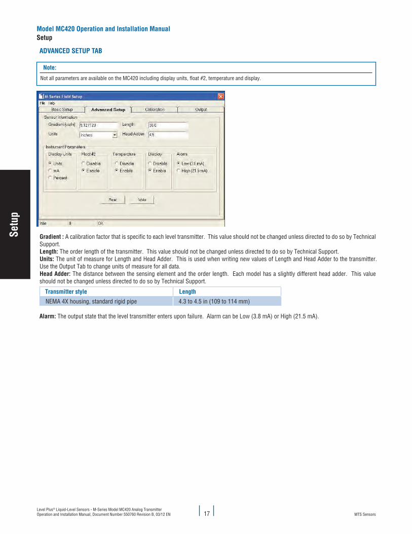
aDvaNceD SeTuP TaB
Note:
Not all parameters are available on the MC420 including display units, float #2, temperature and display.
Gradient : A calibration factor that is specific to each level transmitter. This value should not be changed unless directed to do so by Technical Support.length: The order length of the transmitter. This value should not be changed unless directed to do so by Technical Support.units: The unit of measure for Length and Head Adder. This is used when writing new values of Length and Head Adder to the transmitter. Use the Output Tab to change units of measure for all data.head adder: The distance between the sensing element and the order length. Each model has a slightly different head adder. This value should not be changed unless directed to do so by Technical Support.
Transmitter style length
NEMA 4X housing, standard rigid pipe 4.3 to 4.5 in (109 to 114 mm)
alarm: The output state that the level transmitter enters upon failure. Alarm can be Low (3.8 mA) or High (21.5 mA).
Model Mc420 Operation and Installation ManualSetup
Setu
p
MTS SensorsLevel Plus® Liquid-Level Sensors - M-Series Model MC420 Analog Transmitter
Operation and Installation Manual, Document Number 550760 Revision B, 03/12 EN
Model Mc420 Operation and Installation ManualSetup
18
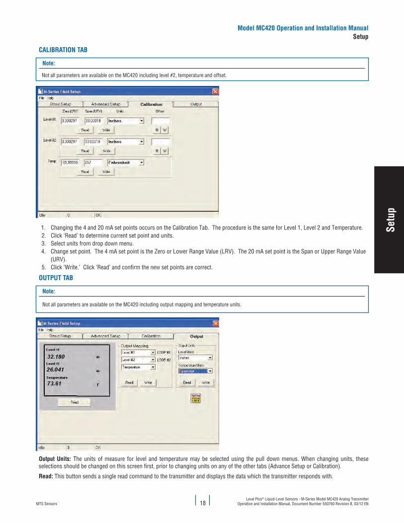
calIBRaTION TaB
Note:
Not all parameters are available on the MC420 including level #2, temperature and offset.
1. Changing the 4 and 20 mA set points occurs on the Calibration Tab. The procedure is the same for Level 1, Level 2 and Temperature.2. Click ‘Read’ to determine current set point and units.3. Select units from drop down menu.4. Change set point. The 4 mA set point is the Zero or Lower Range Value (LRV). The 20 mA set point is the Span or Upper Range Value
(URV).5. Click ‘Write.’ Click ‘Read’ and confirm the new set points are correct.
OuTPuT TaB
Note:
Not all parameters are available on the MC420 including output mapping and temperature units.
Output units: The units of measure for level and temperature may be selected using the pull down menus. When changing units, these selections should be changed on this screen first, prior to changing units on any of the other tabs (Advance Setup or Calibration).
Read: This button sends a single read command to the transmitter and displays the data which the transmitter responds with.
Setu
p
MTS SensorsLevel Plus® Liquid-Level Sensors - M-Series Model MC420 Analog Transmitter Operation and Installation Manual, Document Number 550760 Revision B, 03/12 EN 19
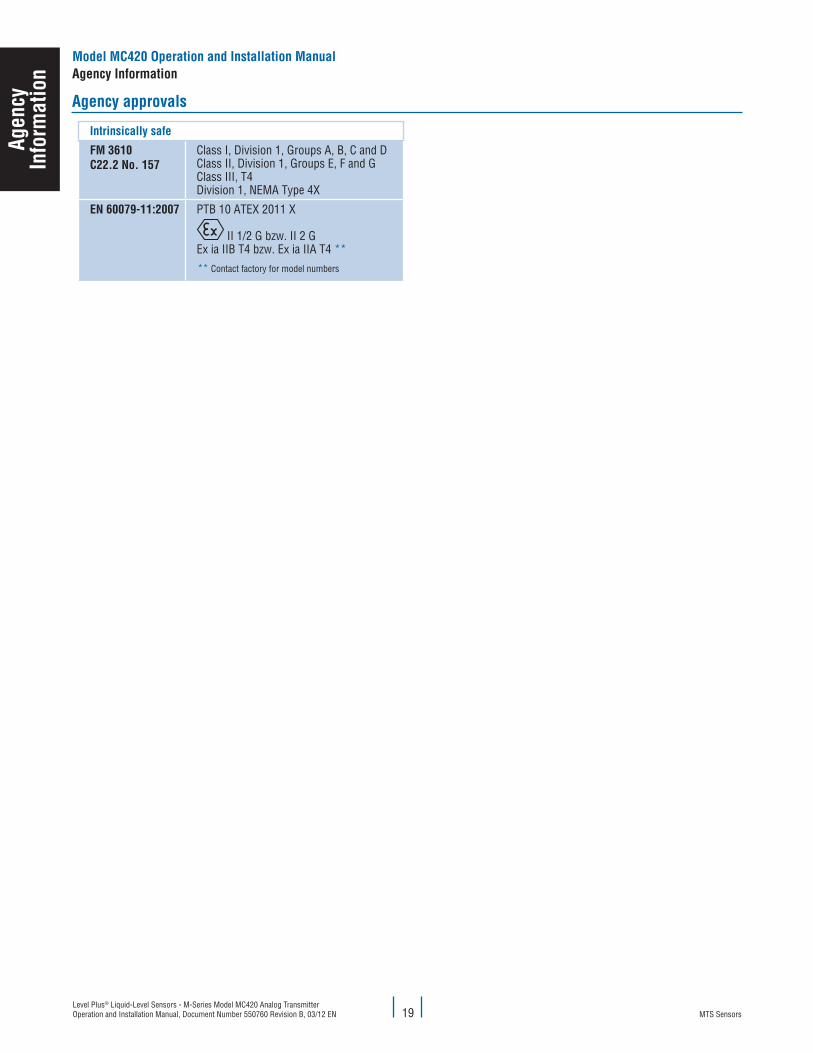
agency approvals
Intrinsically safe
fM 3610c22.2 No. 157
Class I, Division 1, Groups A, B, C and DClass II, Division 1, Groups E, F and GClass III, T4Division 1, NEMA Type 4X
eN 60079-11:2007 PTB 10 ATEX 2011 X
II 1/2 G bzw. II 2 GEx ia IIB T4 bzw. Ex ia IIA T4 **
** Contact factory for model numbers
agen
cyIn
form
atio
nModel Mc420 Operation and Installation Manualagency Information
MTS SensorsLevel Plus® Liquid-Level Sensors - M-Series Model MC420 Analog Transmitter
Operation and Installation Manual, Document Number 550760 Revision B, 03/12 EN
Model Mc420 Operation and Installation Manualagency information
20
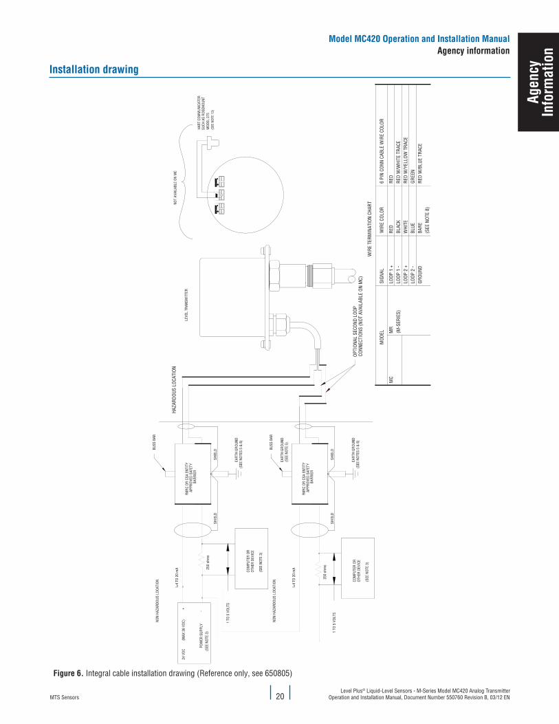
Installation drawing
(SEE
NOT
E 13
)
figure 6. Integral cable installation drawing (Reference only, see 650805)
agen
cyIn
form
atio
n
MTS SensorsLevel Plus® Liquid-Level Sensors - M-Series Model MC420 Analog Transmitter Operation and Installation Manual, Document Number 550760 Revision B, 03/12 EN 21
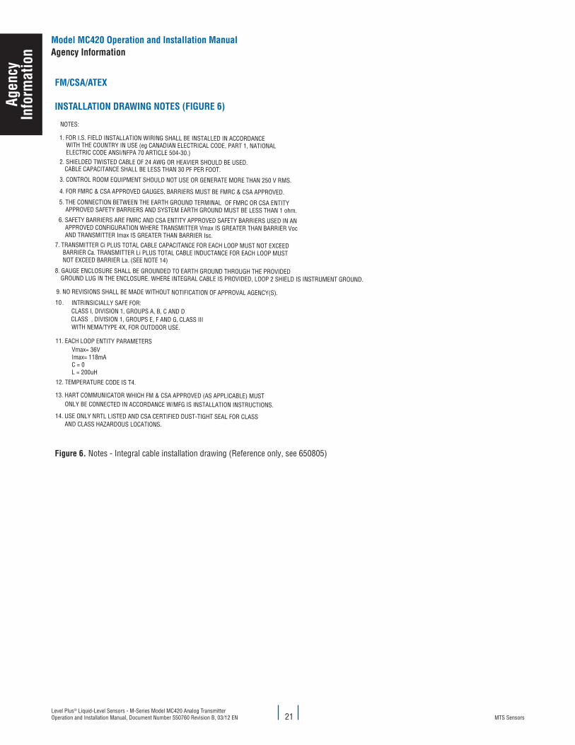
fM/cSa/aTeX
INSTallaTION DRaWING NOTeS (fIGuRe 6)
AND CLASS HAZARDOUS LOCATIONS.14. USE ONLY NRTL LISTED AND CSA CERTIFIED DUST-TIGHT SEAL FOR CLASS
ONLY BE CONNECTED IN ACCORDANCE W/MFG IS INSTALLATION INSTRUCTIONS.
13. HART COMMUNICATOR WHICH FM & CSA APPROVED (AS APPLICABLE) MUST
CLASS IIICLASS , DIVISION 1, GROUPS E, F AND G,
11. EACH LOOP ENTITY PARAMETERS
WITH NEMA/TYPE 4X, FOR OUTDOOR USE.
Vmax= 36VImax= 118mAC = 0L = 200uH
WITH THE COUNTRY IN USE (eg CANADIAN ELECTRICAL CODE, PART 1, NATIONAL
NOT EXCEED BARRIER La. (SEE NOTE 14) BARRIER Ca. TRANSMITTER Li PLUS TOTAL CABLE INDUCTANCE FOR EACH LOOP MUST
7. TRANSMITTER Ci PLUS TOTAL CABLE CAPACITANCE FOR EACH LOOP MUST NOT EXCEED
AND TRANSMITTER Imax IS GREATER THAN BARRIER Isc. APPROVED CONFIGURATION WHERE TRANSMITTER Vmax IS GREATER THAN BARRIER Voc
6. SAFETY BARRIERS ARE FMRC AND CSA ENTITY APPROVED SAFETY BARRIERS USED IN AN
4. FOR FMRC & CSA APPROVED GAUGES, BARRIERS MUST BE FMRC & CSA APPROVED.
8. GAUGE ENCLOSURE SHALL BE GROUNDED TO EARTH GROUND THROUGH THE PROVIDED
APPROVED SAFETY BARRIERS AND SYSTEM EARTH GROUND MUST BE LESS THAN 1 ohm.5. THE CONNECTION BETWEEN THE EARTH GROUND TERMINAL
3. CONTROL ROOM EQUIPMENT SHOULD NOT USE OR GENERATE MORE THAN 250 V RMS.
1. FOR I.S. FIELD INSTALLATION WIRING SHALL BE INSTALLED IN ACCORDANCE
10CLASS I, DIVISION 1, GROUPS A, B, C AND DINTRINSICIALLY SAFE FOR:
9. NO REVISIONS SHALL BE MADE WITHOUT
GROUND LUG IN THE ENCLOSURE. WHERE INTEGRAL CABLE IS PROVIDED, LOOP 2 SHIELD IS INSTRUMENT GROUND.
CABLE CAPACITANCE SHALL BE LESS THAN 30 PF PER FOOT.
.
2. SHIELDED TWISTED CABLE OF 24 AWG OR HEAVIER SHOULD BE USED.
NOTES:
OF FMRC OR CSA ENTITY
NOTIFICATION OF APPROVAL AGENCY(S).
12. TEMPERATURE CODE IS T4.
ELECTRIC CODE ANSI/NFPA 70 ARTICLE 504-30.)
figure 6. Notes - Integral cable installation drawing (Reference only, see 650805)
agen
cyIn
form
atio
nModel Mc420 Operation and Installation Manualagency Information
MTS SensorsLevel Plus® Liquid-Level Sensors - M-Series Model MC420 Analog Transmitter
Operation and Installation Manual, Document Number 550760 Revision B, 03/12 EN22
fM/cSa/aTeX
INSTallaTION DRaWING NOTeS (fIGuRe 6)
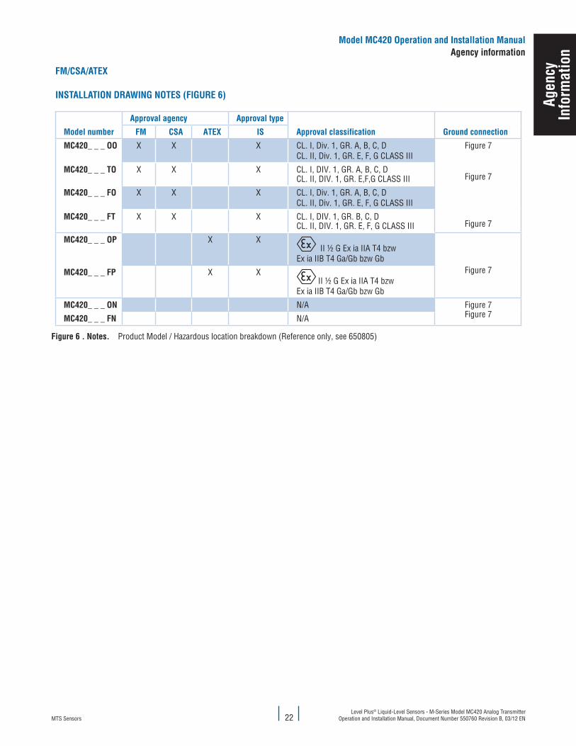
Model number
approval agency approval type
approval classification Ground connection fM cSa aTeX IS
Mc420_ _ _ OO X X X CL. I, Div. 1, GR. A, B, C, DCL. II, Div. 1, GR. E, F, G CLASS III
Figure 7
Figure 7
Figure 7
Mc420_ _ _ TO X X X CL. I, DIV. 1, GR. A, B, C, DCL. II, DIV. 1, GR. E,F,G CLASS III
Mc420_ _ _ fO X X X CL. I, Div. 1, GR. A, B, C, DCL. II, Div. 1, GR. E, F, G CLASS III
Mc420_ _ _ fT X X X CL. I, DIV. 1, GR. B, C, DCL. II, DIV. 1, GR. E, F, G CLASS III
Mc420_ _ _ OP X X II ½ G Ex ia IIA T4 bzw
Ex ia IIB T4 Ga/Gb bzw GbFigure 7Mc420_ _ _ fP X X
II ½ G Ex ia IIA T4 bzwEx ia IIB T4 Ga/Gb bzw Gb
Mc420_ _ _ ON N/A Figure 7Figure 7Mc420_ _ _ fN N/A
figure 6 . Notes. Product Model / Hazardous location breakdown (Reference only, see 650805)
Model Mc420 Operation and Installation Manualagency information
agen
cyIn
form
atio
n
MTS SensorsLevel Plus® Liquid-Level Sensors - M-Series Model MC420 Analog Transmitter Operation and Installation Manual, Document Number 550760 Revision B, 03/12 EN 23
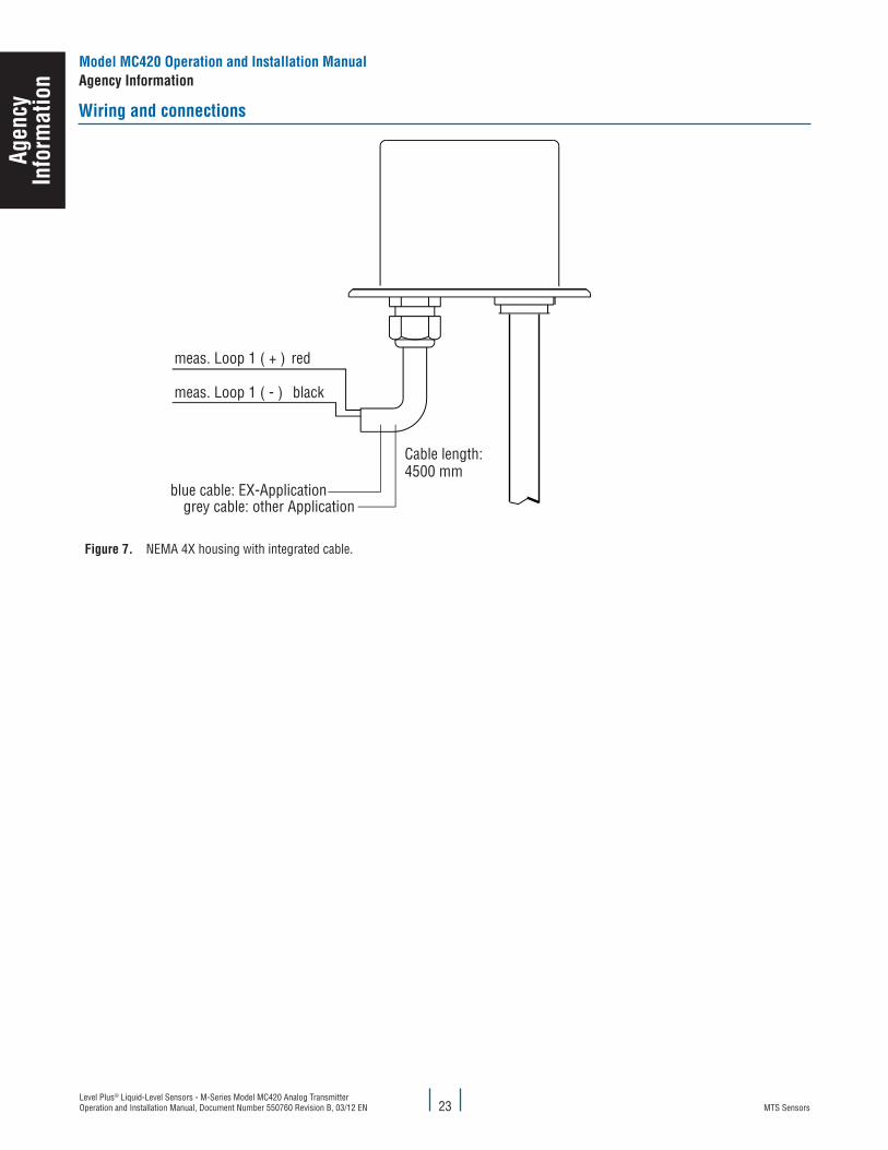
Wiring and connections
figure 7. NEMA 4X housing with integrated cable.
agen
cyIn
form
atio
nModel Mc420 Operation and Installation Manualagency Information
MTS SensorsLevel Plus® Liquid-Level Sensors - M-Series Model MC420 Analog Transmitter
Operation and Installation Manual, Document Number 550760 Revision B, 03/12 EN24
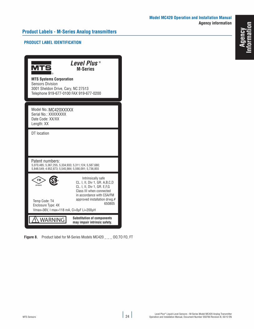
Product labels - M-Series analog transmitters
PRODucT laBel IDeNTIfIcaTION
Vmax=36V, I max=118 mA, Ci=0μF Li=200μH
Intrinsically safeCL. I, II, Div 1, GR. A,B,C,DCL. I, II, Div 1, GR. E,F,GClass III when connectedin accordance with CSA/FMapproved installation drwg.# 650805
MC420XXXXX
figure 8. Product label for M-Series Models MC420 _ _ _ OO,TO FO, FT
Model Mc420 Operation and Installation Manualagency information
agen
cyIn
form
atio
n
MTS SensorsLevel Plus® Liquid-Level Sensors - M-Series Model MC420 Analog Transmitter Operation and Installation Manual, Document Number 550760 Revision B, 03/12 EN 25
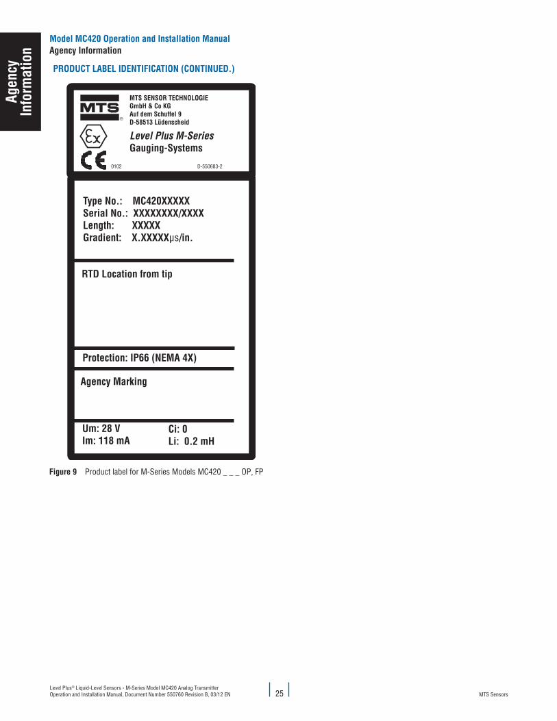
PRODucT laBel IDeNTIfIcaTION (cONTINueD.)
®
Um: 28 V Im: 118 mA
Ci: 0 Li: 0.2 mH
0102 D-550683-2
MTS SENSOR TECHNOLOGIEGmbH & Co KGAuf dem Schuffel 9D-58513 Lüdenscheid
Level Plus M-SeriesGauging-Systems
Type No.: MC420XXXXXSerial No.: XXXXXXXX/XXXX Length: XXXXXGradient: X.XXXXXμs/in.
RTD Location from tip
Protection: IP66 (NEMA 4X)
Agency Marking
figure 9 Product label for M-Series Models MC420 _ _ _ OP, FP
agen
cyIn
form
atio
nModel Mc420 Operation and Installation Manualagency Information
MTS SensorsLevel Plus® Liquid-Level Sensors - M-Series Model MC420 Analog Transmitter
Operation and Installation Manual, Document Number 550760 Revision B, 03/12 EN26
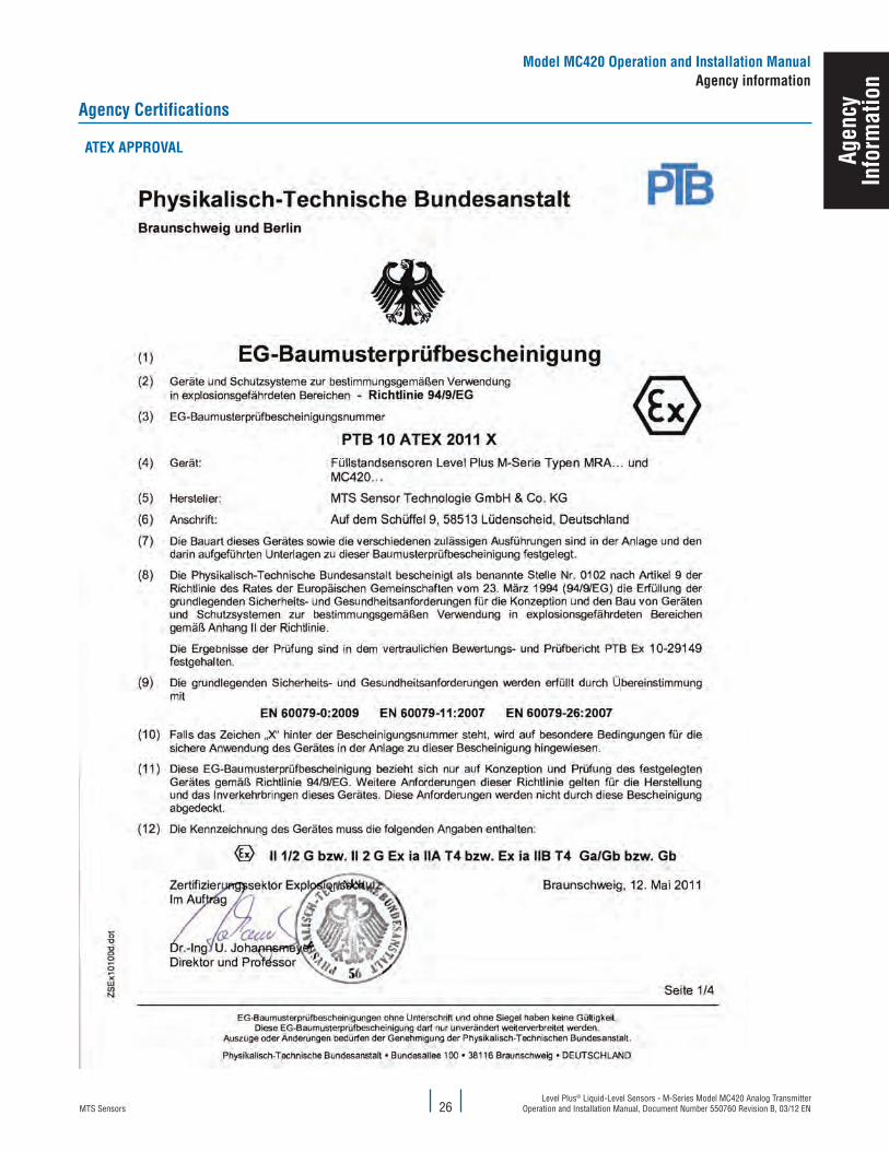
agency certifications
aTeX aPPROval
Model Mc420 Operation and Installation Manualagency information
agen
cyIn
form
atio
n

MTS SensorsLevel Plus® Liquid-Level Sensors - M-Series Model MC420 Analog Transmitter Operation and Installation Manual, Document Number 550760 Revision B, 03/12 EN 27
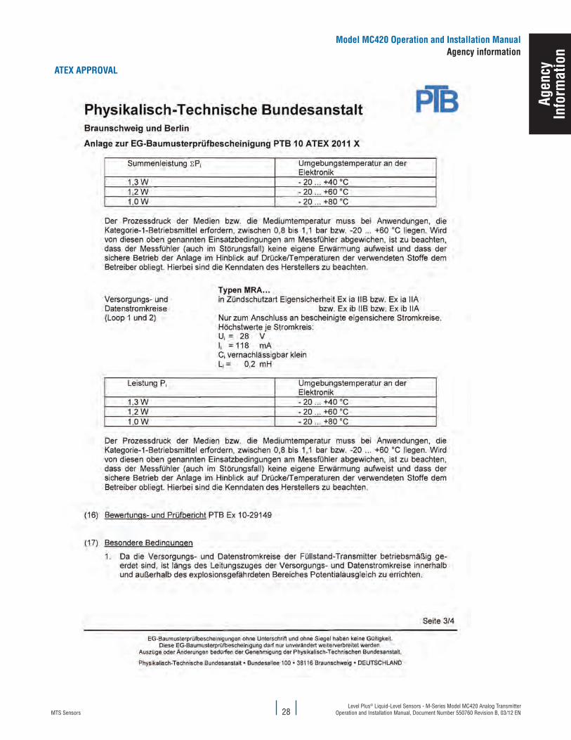
aTeX aPPROval
agen
cyIn
form
atio
nModel Mc420 Operation and Installation Manualagency Information
MTS SensorsLevel Plus® Liquid-Level Sensors - M-Series Model MC420 Analog Transmitter
Operation and Installation Manual, Document Number 550760 Revision B, 03/12 EN
aTeX aPPROval
28
Model Mc420 Operation and Installation Manualagency information
agen
cyIn
form
atio
n

MTS SensorsLevel Plus® Liquid-Level Sensors - M-Series Model MC420 Analog Transmitter Operation and Installation Manual, Document Number 550760 Revision B, 03/12 EN 29
aTeX aPPROval
agen
cyIn
form
atio
nModel Mc420 Operation and Installation Manualagency Information
MTS SensorsLevel Plus® Liquid-Level Sensors - M-Series Model MC420 Analog Transmitter
Operation and Installation Manual, Document Number 550760 Revision B, 03/12 EN30
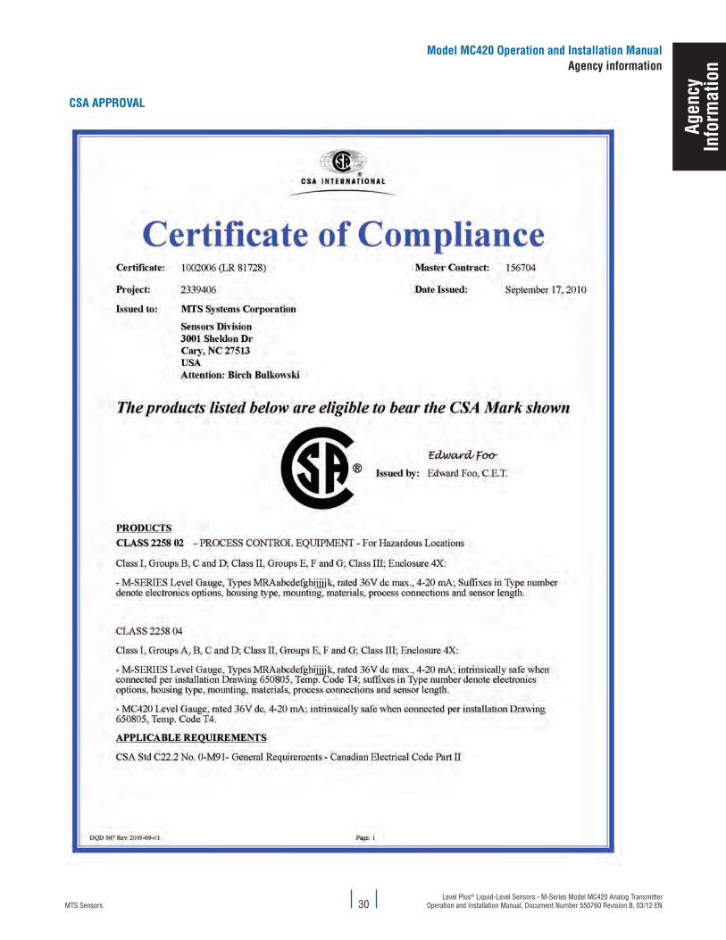
cSa aPPROval
Model Mc420 Operation and Installation Manualagency information
agen
cyIn
form
atio
n
MTS SensorsLevel Plus® Liquid-Level Sensors - M-Series Model MC420 Analog Transmitter Operation and Installation Manual, Document Number 550760 Revision B, 03/12 EN
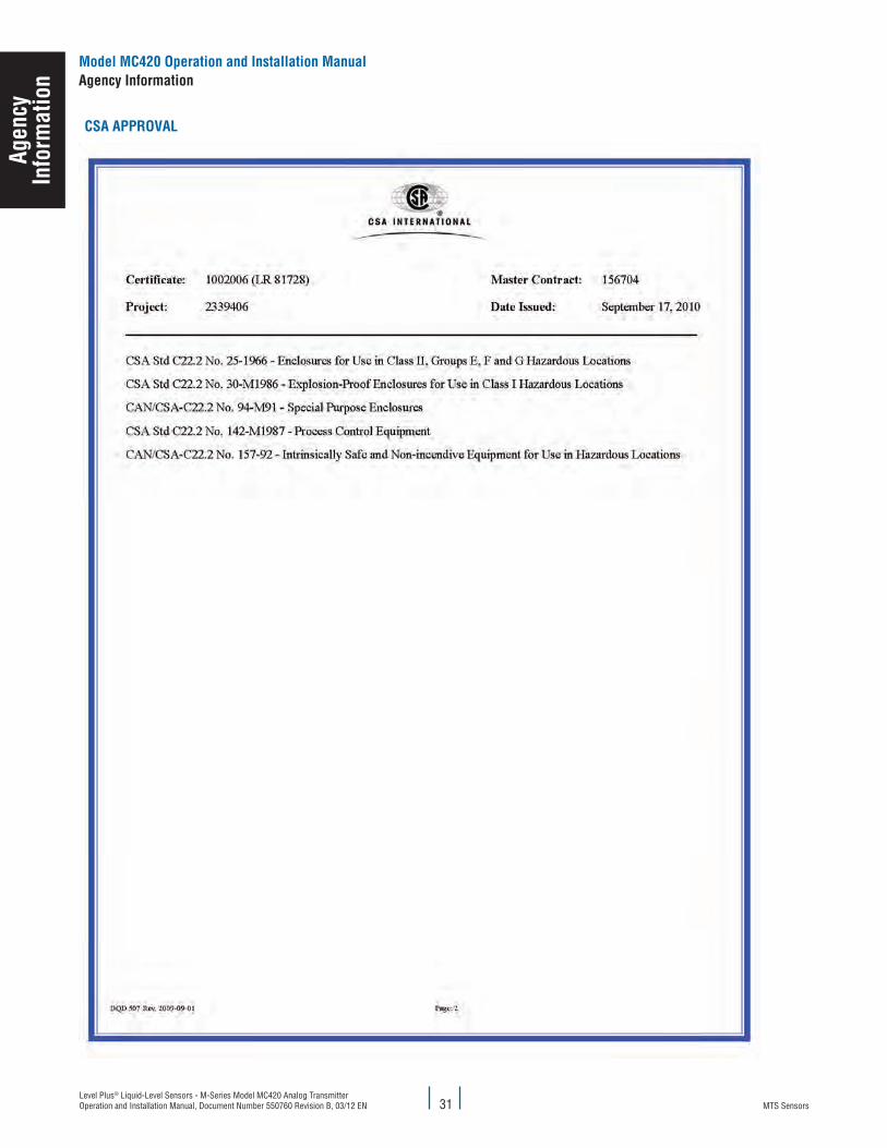
cSa aPPROval
31
agen
cyIn
form
atio
nModel Mc420 Operation and Installation Manualagency Information
MTS SensorsLevel Plus® Liquid-Level Sensors - M-Series Model MC420 Analog Transmitter
Operation and Installation Manual, Document Number 550760 Revision B, 03/12 EN32
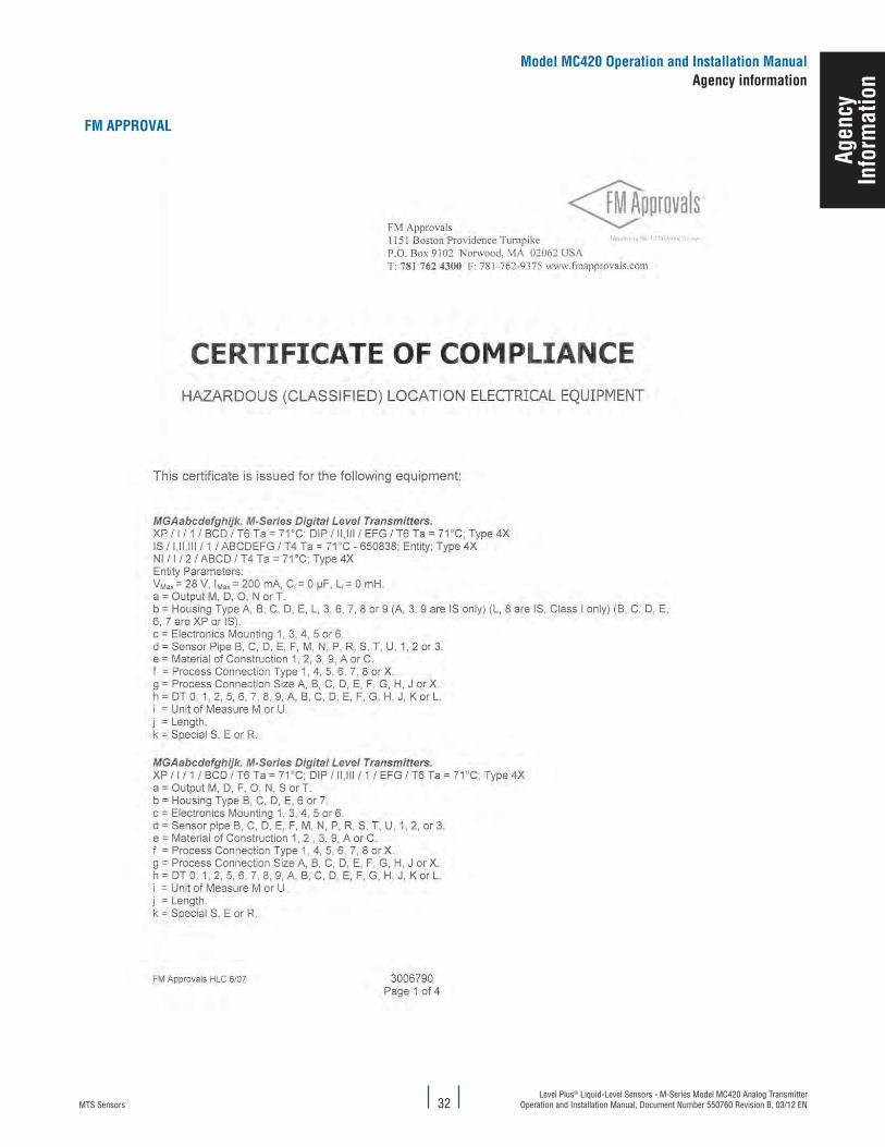
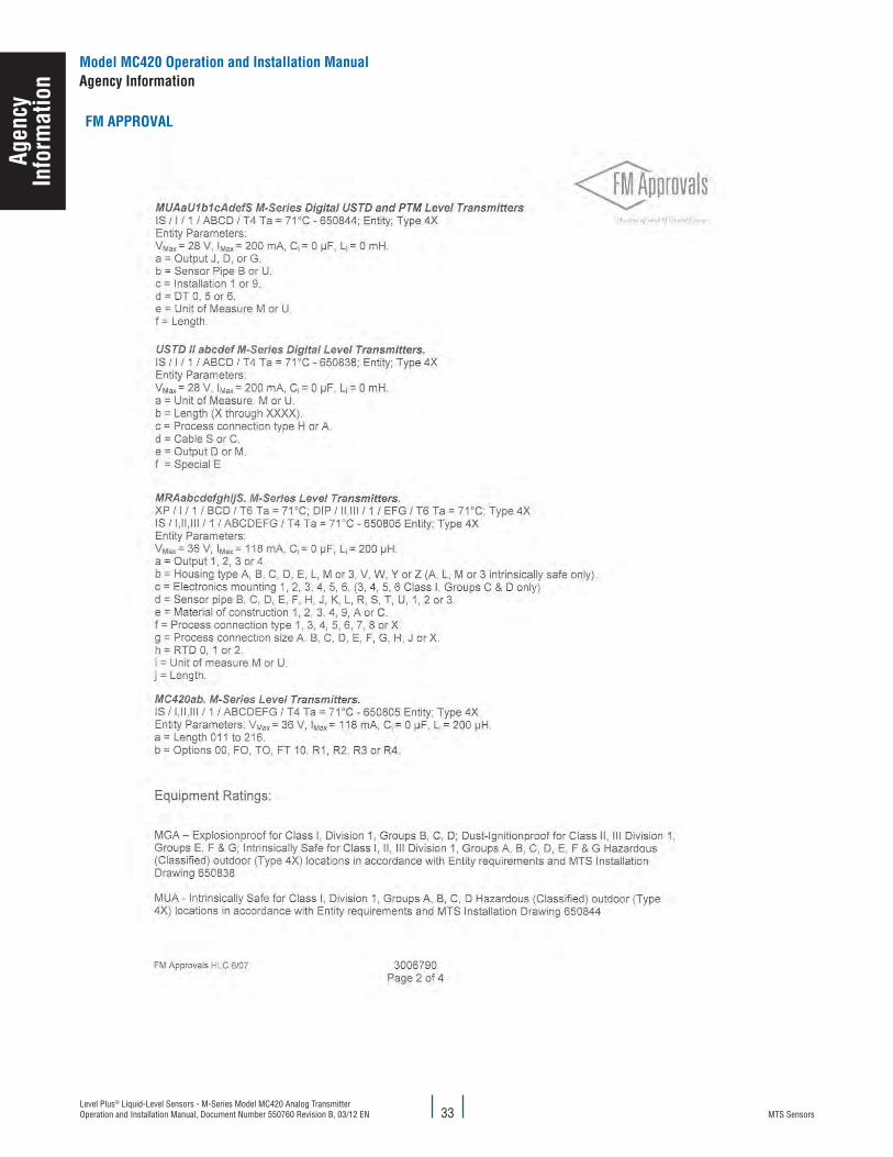
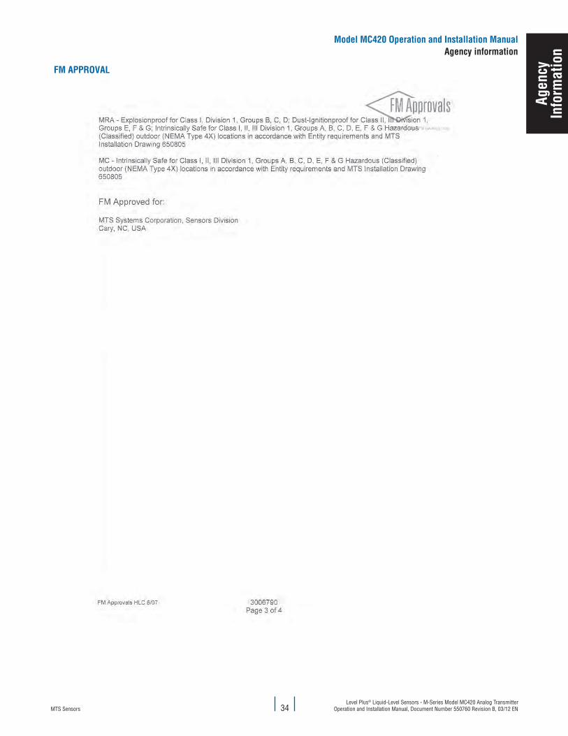
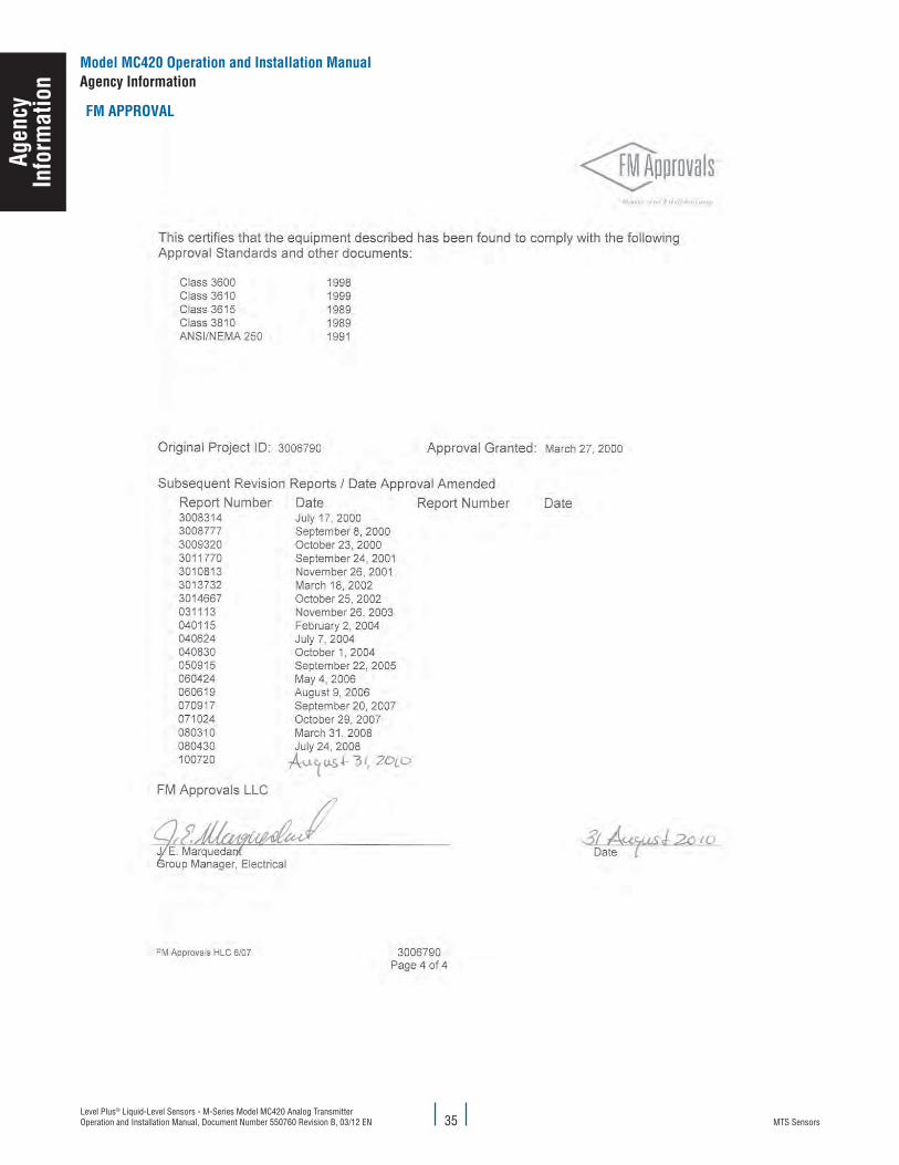
fM aPPROval
Model Mc420 Operation and Installation Manualagency information
agen
cyIn
form
atio
n
MTS SensorsLevel Plus® Liquid-Level Sensors - M-Series Model MC420 Analog Transmitter Operation and Installation Manual, Document Number 550760 Revision B, 03/12 EN 33
fM aPPROval
agen
cyIn
form
atio
nModel Mc420 Operation and Installation Manualagency Information
MTS SensorsLevel Plus® Liquid-Level Sensors - M-Series Model MC420 Analog Transmitter
Operation and Installation Manual, Document Number 550760 Revision B, 03/12 EN34
fM aPPROval
Model Mc420 Operation and Installation Manualagency information
agen
cyIn
form
atio
n
MTS SensorsLevel Plus® Liquid-Level Sensors - M-Series Model MC420 Analog Transmitter Operation and Installation Manual, Document Number 550760 Revision B, 03/12 EN 35
fM aPPROval
agen
cyIn
form
atio
nModel Mc420 Operation and Installation Manualagency Information

MTS, Temposonics and Level Plus are registered trademarks of MTS Systems Corporation. All other trademarks are the property of their respective owners. Printed in USA. Copyright © 2012 MTS Systems Corporation. All Rights Reserved in all media.
All specifications are subject to change. Contact MTS for specifications and engineering drawings that are critical to your application. Drawings contained in this document are for reference only. Go to http://www.mtssensors.com for the latest product information. Drawings contained in this document are for reference
only. Go to http://www.mtssensors.com for the latest product information
Document Part Number: 550760 Revision B, 03/12, 04/12 eN
MTS Sensor TechnologieGmbh & co. kG
Auf dem Schüffel 9D - 58513 Lüdenscheid, GermanyTel.: +49-2351-9587-0Fax: +49-2351-56491
e-mail: [email protected]://www.mtssensor.de
MTS Systems corporationSensors Division
3001 Sheldon DriveCary, North Carolina,27513, USATel.: +1-800-633-7609Fax: +1-919-677-2343
+1-800-498-4442 e-mail: [email protected]://www.mtssensors.com
SENSORS
®
MTS Sensors Technologycorporation
737 Aihara-cho, Machida-shiTokyo 194-0211, JapanTel.: +81-42-775-3838Fax: +81-42-775-5516
e-mail: [email protected]://www.mtssensor.co.jp