operation and maintenance instructions · installation, operation & maintenance xomox®...
TRANSCRIPT

www.cranecpe.com
OPERATION AND MAINTENANCE INSTRUCTIONS
XOMOX® Performance Valves Types 127; 067; 0367
XP3 / XP4DSR / HF4D
brands you trust.

www.cranecpe.com2
XOMOX® Performance Valves, Types 127, 067, 0367, XP3, XP4D, SR & HF4DInstallation, Operation & Maintenance
XOMOX® Performance Valves, Types 127, 067, 0367, XP3, XP4D, SR & HF4DInstallation, Operation & Maintenance
1. VALVE APPLICATIONSXOMOX Performance Valves – XP3 / XP4D / SR / HF4D– shall be installed within the certified limits of pressure and temperature ratings, refer to the valve label/markings.
2. SAFETY INFORMATION2.1 General Safety InformationThe same safety requirements apply for valves as for the piping system into which they are installed, and the plant control system to which they are connected. The following instructions provide such advice only, which shall be observed additionally. Separate safety information is included in the manual of the actuator attached to the valve
These valves should not be used in service conditions where materials of its parts in contact with the fluids are not suitable.
WARNING!
Subsequent caution- and warning comments are not adhered to, danger can result and the guarantee of the manufacturer will become void.The manufacturer is at your disposal for further information – please see contact information on the last page.
WARNING!
2.2 Important Information for the UserThe following will consider information of the installation and operation of XOMOX® Performance Valves (Types 127; 067; 0367 – XP3, XP4D, SR & HF4D). Before proceeding, please pay attention to the items presented in the beginning of this instruction manual and make sure that they are being followed in all following matters.
Please be aware, that it is not the liability of the Valve Manufacturer to ensure the following:• the valve is only used following personal protective procedures and
safety practices for protection as per the policy of the plant in which the valve is installed.
• the valve is only used as specified in Section 1 “Valve Application.”• an actuator for a valve supplied bare shaft has been sized and assembled
to the valve according to the manufacturer’s recommendations.• such actuator has been adjusted correctly in the valve’s end positions –
specifically in the OPEN end position.• the design of the valve’s housing allows the standard additional forces
and bending torques, which are customary in such piping systems.• the pipe system and the plant control system have been installed by
experts and that these systems are regularly inspected.• the fluid flow velocity in this pipe system is limited to the standard values,
i.e. 4 m/s (13 ft/sec) for liquids, and no abnormal service conditions occur, such as vibrations, water hammer or cavitation.
• the contents of solid – especially hard and sharp – particulates in the fluid are known and accepted by the manufacturer XOMOX.
• valves used at fluid temperatures >50°C (122°F) or <-20°C (-4°F) are protected together with the pipe connection ends from contact with the user.
• only trained and duly authorized personnel, who are trained in all aspects of plant safety – specifically for those fluids under pressure – shall operate, inspect and repair these valves.
• personnel shall read and understand the requirements of this manual.
• Only original XOMOX spare parts may be installed.• Never reassemble with used gasket, sleeve, membrane or packing.• Clean components, stuffing box and stem to ensure that they are
completely free of wear, solids or corrosion. • Ensure that the gland, bolts and nuts run freely on threads – it is
recommended that bolting are new or in “like new” condition.• Make sure that the gland follower nose is clean and fits properly into
the stuffing box.• Ensure that the bottom of the stuffing box – located in press-ring and
packing cover (if XP4D) – is flat and perpendicular to the valve stem.• Make sure that the HF4D plug stem has a surface finish of 32RMS
Ra0.8 or better and the stuffing box has a surface finish of 64RMS Ra1.6 post cleaning.
• Obtain the correct equipment to setup packing described in this document.
• Refer product literature for application date.• Review all instructions below before proceeding with installation.• If the valve is to be placed into short/long term storage, the valve
should be cycled at least three times quarterly.
WARNING!
2.3 Special Kinds of DangerDo not use thick elastomeric gaskets, as this may lead to external leakage of the valve. The gasket used shall support and overlap the mating flange surface of the valve at both sides completely.
• Before a valve is removed from the pipe, or the plug (or cover) from the valve body is disassembled, make sure that the media in the pipe system is completely depressurized.
• Valves in end-of-line-position: For normal service, a valve shall be used only if a blind flange is assembled downstream (unless otherwise noted on the valve).
• If a valve used in end-of-line-position shall be opened under pressure, open the valve very carefully; the fluid can splash out with high velocity.
• If a valve shall be removed from the pipeline, make sure that the pipe system is completely drained before the valve is removed from the pipeline. Be extra careful of residual amounts of the fluid that may remain trapped in the valve and/or in the pipeline.
WARNING!
GENERAL INFORMATION

3www.cranecpe.com
XOMOX® Performance Valves, Types 127, 067, 0367, XP3, XP4D, SR & HF4DInstallation, Operation & Maintenance
XOMOX® Performance Valves, Types 127, 067, 0367, XP3, XP4D, SR & HF4DInstallation, Operation & Maintenance
About Crane XOMOXXOMOX International is a world leader in the manufacture of Sleeved Plug Valves that continues to strive for best-in-class solutions for our customers.
Our comprehensive portfolio of trusted products have been designed to meet the strictest emission requirements and handle complex applications such as phosgene, HCN and HF derivatives.
Reliable Operation XOMOX valves have proven themselves with long-term, trouble-free service in a wide variety of applications.
When applied within their pressure and temperature limitations, properly installed, adjusted and operated, these valves should require minimum attention and lower your long-term ownership costs.
In case there are any questions, please contact your CRANE ChemPharma, XOMOX representative, XOMOX Service Center or the factory. Contact information can be found on the last page of this manual or on our website.
Important InformationThe following information, procedures and illustrations have been prepared to assist the user in assembly, installation and operation of XOMOX Performance Valves – XP3, XP4D, SR & HF4D. Please read and make sure to fully understand these instructions.
Please Notice These instructions have been prepared for valves as they are currently manufactured. If you have an older design valve that requires repair, please contact the factory and make sure that you have the correct repair parts and necessary instructions.
INTRODUCTION
XOMOX® Performance Valves – XP3 and XP4D
Patent Pending no. 299 03 320Applied for European and international patents

www.cranecpe.com4
XOMOX® Performance Valves, Types 127, 067, 0367, XP3, XP4D, SR & HF4DInstallation, Operation & Maintenance
XOMOX® Performance Valves, Types 127, 067, 0367, XP3, XP4D, SR & HF4DInstallation, Operation & Maintenance
INSTRUCTIONS – DISASSEMBLY
MEDIA EXPOSURE.Depressurize, clean and neutralize any media that may remain in the valve and/or the pipeline. In case the valve is in the pipeline, you should follow your line entry procedures.Make sure to always use and wear appropriate safety attire.
WARNING!
1. Remove the hub (or e.g. actuator and bracket).
2. Loosen the cover bolts (or nuts) approximately 4 turns each, being careful not to allow the release of the valve cover. Remove nuts and studs of push follower in case of XP4D and HF4D design
3. Rotate the plug stem ¼ turn to release any trapped pressure within the valve.
4. Remove the valve cover.
5. Use a wrench to turn the plug – remove XP3, XP4D, SR and HF4D plug kit
6. Remove body gasket without damaging body’s surfaces
7. Remove sleeve without damaging body’s surfaces
INSPECTION
See pictures above.For best sealing results, inspect the following components:1. The seal surface on the plug kit and port´s radii’s.
2. The metallic membrane surface of plug kit.
3. The seal surface of the cover
4. The body seal surface online and that aligns with the cover.
5. The sleeve.
These surfaces should be free from defects, which are typically caused by corrosion, erosion, improper handling or improper storage of a disassembled valve.
If defects are found on any of the parts mentioned above, the valve must not be repaired nor operated.

5www.cranecpe.com
XOMOX® Performance Valves, Types 127, 067, 0367, XP3, XP4D, SR & HF4DInstallation, Operation & Maintenance
XOMOX® Performance Valves, Types 127, 067, 0367, XP3, XP4D, SR & HF4DInstallation, Operation & Maintenance
INSTRUCTIONS – REASSEMBLY
4D Version Preparation Only(FRA) 4D version: Introduire 4D packing, positionner le fouloir et orienter celui-ci (petits perçages au-dessus des taraudages).
(ENG) 4D version: Introduce 4D packing, position the gland and make needed orientations (small holes above the tapping).
(GER) 4D Version: 4D Verpackung einführen, die Positionierung des Folgers und Führung desselben (kleine Löcher über dem Gewinde).
(SPA) Versión 4D: Introducir embalaje 4D, posicionar el seguidor y guiar los mismos (pequeños agujeros encima de los hilos).
5.1.1 Install the 4D packing according to Table 1 below.
Table 1: Packing Configuration
SIZE (DN & INCH.) 1X PIECE PACKING 2 PACKING RING*
1/2“ – 1“
1 1/2” – 12”
(*) NPS 14-16-18-20-24 4 rings

www.cranecpe.com6
XOMOX® Performance Valves, Types 127, 067, 0367, XP3, XP4D, SR & HF4DInstallation, Operation & Maintenance
XOMOX® Performance Valves, Types 127, 067, 0367, XP3, XP4D, SR & HF4DInstallation, Operation & Maintenance
(FRA) Mettre en place le joint de couvercle puis introduire le plug en position ouverte.
(ENG) Insert the cover gasket and the plug in open position.
(Ger) Die Deckeldichtung und den Stecker in der Öffnungsstellung.
(SPA) Montar la junta de la tapa e insertar la clavija en la posición abierta.
With 4D design – orientation of the plug must be correct in order to allow installation of the cover, adjusting screws and gland.
CAUTION!
(FRA) Pousser le plug sur la presse pour obtenir le contact entre joint de couvercle et membrane métallique.
(ENG) With the aid of the press, push the plug to make contact between the caver gasket and the metal membrane.
(GER) Schieben des Steckers an der Presse, den Kontakt zwischen Deckeldichtung und Metallmembran zu erhalten.
(SPA) Empujar el tapón en la prensa para obtener el contacto entre junta de la cubierta y la membrana de metal.
(FRA) Introduire le joint torique de couvercle (optionnel) puis positionner le couvercle sur le corps.
(ENG) Insert the cover weather O-ring (optional) and position the cover onto the body.
(GER) Setzen Sie den Deckelwetter O-Ring (optional) ein und stellen Sie die Abdeckung auf den Körper.
(SPA) Inserte la junta tórica de la tapa (opcional) y luego coloque la tapa sobre el cuerpo
With 4D design – orientation of the cover must be correct in order to allow installation of the adjusting screws and gland.
CAUTION!
INSTRUCTIONS – REASSEMBLY

7www.cranecpe.com
XOMOX® Performance Valves, Types 127, 067, 0367, XP3, XP4D, SR & HF4DInstallation, Operation & Maintenance
XOMOX® Performance Valves, Types 127, 067, 0367, XP3, XP4D, SR & HF4DInstallation, Operation & Maintenance
(FRA) Installez la visserie lubrifié et serré en pour atteindre le contact métallique avec le corps, ne pas dépasser les valeurs de couples indiques dans les tables ci-dessous.
(ENG) Install the lubricated bolts; tighten the bolts in order to reach a metallic contact with the body – make sure not to exceed the torque values indicated in the tables below.
(GER) Installieren der geschmierten Schrauben und engt den Metallkontakt mit dem Körper zu erreichen, nicht der Wert überschreitet angegebene Paare in.
(SPA) Instalar los tornillos lubricados y apretado para alcanzar el contacto de metal con el cuerpo, que no exceda el valor indicado parejas en las siguientes tablas.
METRIC
DN UNC Qty A4-70 Torque lbs-ft
15 - 20
M8
4
2025 4
40 4
50 - 80 M10 4 40
100 M12 4 70
150
M16
4
180200 6
250 8
300 M20 8 360
IMPERIAL
NPS UNC QTYA193-B7 TORQUE LBS-FT
A193-B8 TORQUE LBS-FT
1/2 – 3/4 5/16 –18 4 16 6
1
11/2 3/8 –16 4 29 9
2 - 3 7/16 –14 4 46 14
4 1/2 –13 4 70 21
6 5/8 – 11 4 139 42
8 6
10 8
12 3/4 – 10 8 247 75
16 -18 8
20 -24 1¼ – 8 8 900 375
VALVE DAMAGE.DO NOT exceed maximum torque values as this may lead to personal injury or damage of the valve.
CAUTION!
INSTRUCTIONS – REASSEMBLY
www.cranecpe.com8
XOMOX® Performance Valves, Types 127, 067, 0367, XP3, XP4D, SR & HF4DInstallation, Operation & Maintenance
XOMOX® Performance Valves, Types 127, 067, 0367, XP3, XP4D, SR & HF4DInstallation, Operation & Maintenance
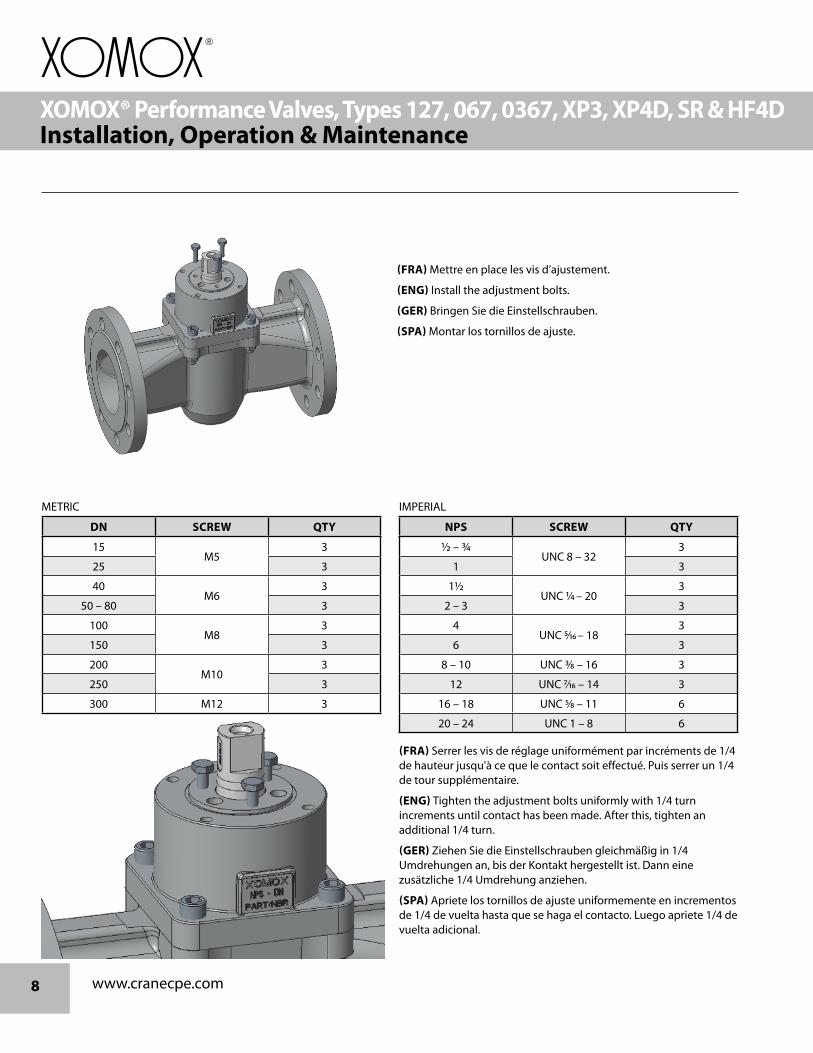
(FRA) Mettre en place les vis d’ajustement.
(ENG) Install the adjustment bolts.
(GER) Bringen Sie die Einstellschrauben.
(SPA) Montar los tornillos de ajuste.
METRIC
DN SCREW QTY
15 M5
3
25 3
40 M6
3
50 – 80 3
100 M8
3
150 3
200 M10
3
250 3
300 M12 3
IMPERIAL
NPS SCREW QTY
1/2 – 3/4 UNC 8 – 32
3
1 3
11/2 UNC ¼ – 20
3
2 – 3 3
4 UNC 5/16 – 18
3
6 3
8 – 10 UNC 3/8 – 16 3
12 UNC 7/16 – 14 3
16 – 18 UNC 5/8 – 11 6
20 – 24 UNC 1 – 8 6
(FRA) Serrer les vis de réglage uniformément par incréments de 1/4 de hauteur jusqu'à ce que le contact soit effectué. Puis serrer un 1/4 de tour supplémentaire.
(ENG) Tighten the adjustment bolts uniformly with 1/4 turn increments until contact has been made. After this, tighten an additional 1/4 turn.
(GER) Ziehen Sie die Einstellschrauben gleichmäßig in 1/4 Umdrehungen an, bis der Kontakt hergestellt ist. Dann eine zusätzliche 1/4 Umdrehung anziehen.
(SPA) Apriete los tornillos de ajuste uniformemente en incrementos de 1/4 de vuelta hasta que se haga el contacto. Luego apriete 1/4 de vuelta adicional.
9www.cranecpe.com
XOMOX® Performance Valves, Types 127, 067, 0367, XP3, XP4D, SR & HF4DInstallation, Operation & Maintenance
XOMOX® Performance Valves, Types 127, 067, 0367, XP3, XP4D, SR & HF4DInstallation, Operation & Maintenance
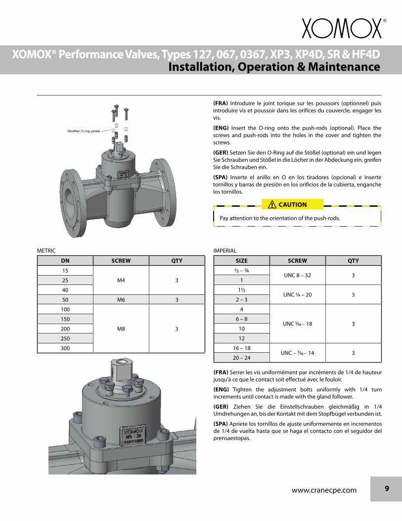
(FRA) Introduire le joint torique sur les poussoirs (optionnel) puis introduire vis et poussoir dans les orifices du couvercle, engager les vis.
(ENG) Insert the O-ring onto the push-rods (optional). Place the screws and push-rods into the holes in the cover and tighten the screws.
(GER) Setzen Sie den O-Ring auf die Stößel (optional) ein und legen Sie Schrauben und Stößel in die Löcher in der Abdeckung ein, greifen Sie die Schrauben ein.
(SPA) Inserte el anillo en O en los tiradores (opcional) e inserte tornillos y barras de presión en los orificios de la cubierta, enganche los tornillos.
Pay attention to the orientation of the push-rods.
CAUTION!
METRIC
DN SCREW QTY
15
M4 325
40
50 M6 3
100
M8 3
150
200
250
300
IMPERIAL
SIZE SCREW QTY
1/2 – 3/4UNC 8 – 32 3
1
11/2UNC ¼ – 20 3
2 – 3
4
UNC 5/16 – 18 36 – 8
10
12
16 – 18UNC – 7/16 – 14 3
20 – 24
(FRA) Serrer les vis uniformément par incréments de 1/4 de hauteur jusqu'à ce que le contact soit effectué avec le fouloir.
(ENG) Tighten the adjustment bolts uniformly with 1/4 turn increments until contact is made with the gland follower.
(GER) Ziehen Sie die Einstellschrauben gleichmäßig in 1/4 Umdrehungen an, bis der Kontakt mit dem Stopfbügel verbunden ist.
(SPA) Apriete los tornillos de ajuste uniformemente en incrementos de 1/4 de vuelta hasta que se haga el contacto con el seguidor del prensaestopas.

www.cranecpe.com10
XOMOX® Performance Valves, Types 127, 067, 0367, XP3, XP4D, SR & HF4DInstallation, Operation & Maintenance
XOMOX® Performance Valves, Types 127, 067, 0367, XP3, XP4D, SR & HF4DInstallation, Operation & Maintenance
Normal running torques may be less than the values shown in the table below.
Valve torque may be greater if the valve is used to control a highly viscous or abrasive medium.
OPERATING TORQUES
XP3 / XP4D Break Torque PN 40 - Class 150 and 300 [Nm]
SIZE PTFE/PTFEX %R-PTFE SLEEVE PTFEXC/XENITH SLEEVE UHMWPE/PFA SLEEVE
Std Built Dry Std Built Dry Std Built Dry Std Built Dry
15 16 24 20 30 21 32 32 47
20 16 24 20 30 21 32 32 47
25 45 68 57 85 61 92 90 136
40 90 136 113 170 122 183 181 271
50 124 186 155 233 168 252 249 373
80 136 203 170 254 183 275 271 407
100 271 407 339 509 366 549 542 814
150 565 847 706 1059 763 1144 1130 1695
200 881 1322 1102 1652 1190 1785 1763 2644
250 1627 2441 2034 3051 2196 3295 3254 4881
300 2373 3559 2966 4449 3203 4805 4745 7118
In case of questions please contact your service center or the XOMOX manufacturing site.
11www.cranecpe.com
XOMOX® Performance Valves, Types 127, 067, 0367, XP3, XP4D, SR & HF4DInstallation, Operation & Maintenance
XOMOX® Performance Valves, Types 127, 067, 0367, XP3, XP4D, SR & HF4DInstallation, Operation & Maintenance
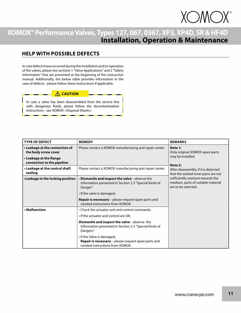
In case defects have occurred during the installation and/or operation of the valves, please see sections 1 “Valve Applications“ and 2 “Safety Information” that are presented at the beginning of this instruction manual. Additionally, the below table provides information in the case of defects - please follow these instructions if applicable.
In case a valve has been disassembled from the service line with dangerous fluids, please follow the decontamination instructions - see XOMOX <Disposal Sheets>
CAUTION!
HELP WITH POSSIBLE DEFECTS
TYPE OF DEFECT REMEDY REMARKS
• Leakage at the connection of the body screw cover
• Leakage at the flange connection to the pipeline
Please contact a XOMOX manufacturing and repair center. Note 1:Only original XOMOX spare parts may be installed.
Note 2:After disassembly, if it is detected that the wetted inner parts are not sufficiently resistant towards the medium, parts of suitable material are to be selected.
• Leakage at the control shaft sealing
Please contact a XOMOX manufacturing and repair center.
•Leakage in the locking position • Dismantle and inspect the valve - observe the information presented in Section 2.3 “Special Kinds of Danger”.
• If the valve is damaged;
Repair is necessary – please request spare parts and needed instructions from XOMOX.
• Malfunction • Check the actuator unit and control commands.
• If the actuator and control are OK;
Dismantle and inspect the valve - observe the information presented in Section 2.3 “Special Kinds of Dangers”.
• If the Valve is damaged; Repair is necessary – please request spare parts and needed instructions from XOMOX.

brands you trust.
®
®
CPE-
XOM
OX-
PV12
7-06
7-03
67-X
P3-X
P4D
-IM-E
N-L
T-20
18_0
6_6
Crane Co., and its subsidiaries cannot accept responsibility for possible errors in catalogues, brochures, other printed materials, and website information. Crane Co. reserves the right to alter its products without notice, including products already on order provided that such alteration can be made without changes being necessary in specifications already agreed. All trademarks in this material are property of the Crane Co. or its subsidiaries. The Crane and Crane brands logotype, in alphabetical order, (ALOYCO®, CENTER LINE®, COMPAC-NOZ®, CRANE®, DEPA®, DUO-CHEK®, ELRO®, FLOWSEAL®, JENKINS®, KROMBACH®, NOZ-CHEK®, PACIFIC VALVES®, RESISTOFLEX®, REVO®, SAUNDERS®, STOCKHAM®, TRIANGLE®, UNI-CHEK®, WTA®, and XOMOX®) are registered trademarks of Crane Co. All rights reserved.
Crane ChemPharma & Energy 4526 Research Forest Drive, Suite 400
The Woodlands
Texas 77381, U.S.A. Tel: +1 936 271 6500
Fax:+1 1 (936) 271 6510
www.cranecpe.com