operation and maintenance manual - sondex.net and maintena… · 6 4.2 correct operation this user...
TRANSCRIPT

Operation and Maintenance Manual Sondex All-Welded Heat Exchangers (SAW)

2 2
The contents of this publication are based on the latest information available and the materials that are used at the time of printing. However, because of rapid developments in this field we cannot be held liable for changes in specifications affecting the contents of this publication.
COPYRIGHTCopyright © SONDEX HOLDING A/S. All rights reserved. No part of this publication may be reproduced or distributed without prior written permission of SONDEX HOLDING A/S.

3 3
1 FOREWORD. . . . . . . . . . . . . . . . . . . . . . . . . . . . . . . . . . . . . . . . . . . . . . . . . . . . . . . . . . . . . . . . . . . . . 4
2 INTRODUCTION. . . . . . . . . . . . . . . . . . . . . . . . . . . . . . . . . . . . . . . . . . . . . . . . . . . . . . . . . . . . . . . . . 4
3 SAFETY ALERT NOTICES . . . . . . . . . . . . . . . . . . . . . . . . . . . . . . . . . . . . . . . . . . . . . . . . . . . . . . . . . 4
4 GENERAL . . . . . . . . . . . . . . . . . . . . . . . . . . . . . . . . . . . . . . . . . . . . . . . . . . . . . . . . . . . . . . . . . . . . . . . 5 4.1 Identification of the heat exchanger. . . . . . . . . . . . . . . . . . . . . . . . . . . . . . . . . . . . . . . . . 5 4.2 Correct operation. . . . . . . . . . . . . . . . . . . . . . . . . . . . . . . . . . . . . . . . . . . . . . . . . . . . . . . . . . . 6 4.3 Precautions. . . . . . . . . . . . . . . . . . . . . . . . . . . . . . . . . . . . . . . . . . . . . . . . . . . . . . . . . . . . . . . . . 6 4.4 Thermal design . . . . . . . . . . . . . . . . . . . . . . . . . . . . . . . . . . . . . . . . . . . . . . . . . . . . . . . . . . . . . 7
5 INSTALLATION . . . . . . . . . . . . . . . . . . . . . . . . . . . . . . . . . . . . . . . . . . . . . . . . . . . . . . . . . . . . . . . . . . 8 5.1 Requirements to the installation area. . . . . . . . . . . . . . . . . . . . . . . . . . . . . . . . . . . . . . . . 8 5.2 Transport, lifting, storage. . . . . . . . . . . . . . . . . . . . . . . . . . . . . . . . . . . . . . . . . . . . . . . . . . . . 8 5.3 Installing the pipe connections. . . . . . . . . . . . . . . . . . . . . . . . . . . . . . . . . . . . . . . . . . . . . . 9
6 COMMISSIONING / OPERATION. . . . . . . . . . . . . . . . . . . . . . . . . . . . . . . . . . . . . . . . . . . . . . . . . . 10 6.1 Commissioning and pre-checks . . . . . . . . . . . . . . . . . . . . . . . . . . . . . . . . . . . . . . . . . . . . . 10 6.2 Operation . . . . . . . . . . . . . . . . . . . . . . . . . . . . . . . . . . . . . . . . . . . . . . . . . . . . . . . . . . . . . . . . . . 10 6.3 Shut-down for a short period . . . . . . . . . . . . . . . . . . . . . . . . . . . . . . . . . . . . . . . . . . . . . . . 11 6.4 Shut-down for a long period . . . . . . . . . . . . . . . . . . . . . . . . . . . . . . . . . . . . . . . . . . . . . . . . 11
7 MAINTENANCE . . . . . . . . . . . . . . . . . . . . . . . . . . . . . . . . . . . . . . . . . . . . . . . . . . . . . . . . . . . . . . . . . 12 7.1 Clean in place (CIP) . . . . . . . . . . . . . . . . . . . . . . . . . . . . . . . . . . . . . . . . . . . . . . . . . . . . . . . . . 12 7.2 Some cleaning detergents . . . . . . . . . . . . . . . . . . . . . . . . . . . . . . . . . . . . . . . . . . . . . . . . . . 12 7.4 Maintenance of the heat exchanger . . . . . . . . . . . . . . . . . . . . . . . . . . . . . . . . . . . . . . . . . 12
8 PROBLEM SOLVING . . . . . . . . . . . . . . . . . . . . . . . . . . . . . . . . . . . . . . . . . . . . . . . . . . . . . . . . . . . . . 13
CONTENTS

4 4
Safety Alert NoticeFollowing MUST be respected by installing/running/servicing plate heat exchangers:Keeping current local safety regulations.Before any work begins ensure that the exchangers are pressureless and cooled till under 40ºC.Use gloves for preventing any injury.In all cases ensure that all laws and regulations are strictly kept concerning human/ environment protection.
YELLOW TRIANGLERefer to applicable SAFETY ALERT notices within the manual!All SAFETY ALERT notices are applicable to personal injury and identified by the following symbol.
This manual is applicable for all SAW heat exchangers produced and supplied by SONDEX.
SONDEX can not be held responsible or liable for damage as a result of incorrect installation, use and / or maintenance of SONDEX plate type heat exchanger as well as not complying with the instructions in this manual.
Please note that our heat exchangers are specially designed and built for the operating conditions (pressures, temperatures, capacities and type of fluids) provided by the customer. Sudden pressure peaks beyond the normal operating pressure (or pressure surges) which can occur during starting up or stopping of the system can severely damage the heat exchanger and should be prevented. SONDEX can not be held responsible for any damage as a result of any operation deviating from the original design conditions.
If you wish to alter the design conditions, please contact us. You may only commission the heat exchanger under the modified conditions after inspection and written approval by SONDEX. Also the name plate on the heat exchanger will be adapted.
This manual is a guide for installation, commissioning and maintenance of SAW plate type heat exchangers supplied by SONDEX.
It is meant for those who are responsible for the installation, the use and maintenance of the heat exchangers. We recommend that you read this manual carefully before commencing any work.
1 FOREWORD
2 INTRODUCTION
3 SAFETY ALERT NOTICES

5
Find your local service partner at www.sondex.net
Important: 1. The starting of the SAW must be done without shocks and against colsed valves.2. Max. working pressure may not be exceeded at any time.
Product Side Media Side
Nominel Capasity kW
Heat Surface
Max. Working Pressure bar bar
Max. Differential Pressure bar
Working Temperature Min. °C Max. °C
Volume Ltr. Ltr.
SAW Type Year
Serial No.
Flow Ltr/h
m2
5
4.1 Identification of the heat exchanger
All plate type heat exchangers supplied by SONDEX are provided with a name plate. On this plate the following details are specified:
• type of heat exchanger• year of manufacture• manufacturing number• nominal capacity in kW• transmission area in m2• max. working pressure in bar• test pressure in bar• max. working temperature in °C
4 GENERAL
EXAMPLE
FIG 1
6 6
4.2 Correct operationThis user manual provides information and instructions for correct and safe operation of the unit. Many accidents are caused by incorrect use!It is essential that you study the instructions carefully, and above all, ensure the availability to those who install, maintain and operate the heat exchanger on a daily basis. This manual is of no value if it is not available at the time when your staff needs it.
If a problem occurs with your SONDEX Heat Exchanger which is beyond the scope of this manual, do not hesitate to contact us. The installation should not be put into operation before all indistinctnesses have been solved! To avoid injuries and damages, follow the instructions and local applicable safety regulations. Also take the necessary protective measures, depending on the nature of your process or circumstances related to it, at your plant.
Please note that our plate type heat exchangers are especially designed and built for the operating conditions (pressures, temperatures, capacities and type of fluids) provided by the customer. Sudden pressure peaks beyond the normal operating pressure (or pressure surges) which can occur during starting up or stopping of the system can severely damage the heat exchanger and should be prevented.SONDEX can not be held responsible for any damage as a result of any operation deviating from the original design conditions.
If you wish to alter the design conditions, please contact us. You may only commission the heat exchanger under the modified conditions after inspection and written approval by SONDEX. Also the name plate on the heat exchanger will be adapted.
4.3 PrecautionsAll potential personal injury hazards are identified by safety alert symbol.
Bodily harm can be caused by:• burning as a result of touching the heat exchanger or other parts of the installation;• the uncontrolled release of pressurized media with which the danger of burning and
other injuries is present;• contact with chemicals;• touching sharp edges of the installation.
Damage to equipment can be caused by:• external forces;• corrosion;• chemical action;• erosion;• material exhaustion;• water hammer;• thermal and / or mechanical shock• freezing;• wrong transport / lifting.
7 7
Even after stopping the installation some parts of it can still be hot! The heat exchanger may only be used with the fluids specified on the datasheet.
The hot medium may not flow through the exchanger without the cold medium flowing through. This is to prevent damage to the exchanger. In case the cold medium is present but does not flow while the hot medium is flowing through, the cold medium will start boiling and the exchanger will be damaged.
Sudden pressure and temperature changes should be prevented.
When a heat exchanger (filled with water or a water mixture) which is not in operation is exposed to temperatures below zero, the plates can become deformed.If a danger of frost occurs, the heat exchanger should be drained completely.
If the heat exchanger is being used with temperatures above 60°C or with aggressive fluids, we advise you cover the heat exchanger with a screen plate to prevent the risk of touching.
If welding activities have to be carried out near the heat exchanger, never use the heat exchanger for earthing the construction work.If you have to weld, dismantle the connecting flanges and isolate the heat exchanger from the system.
4.4 Thermal DesignSondex heat exchangers are designed and calculated according to the newest technology.
If performance test has to be carried out, the exchanger must be totally clean.
In the Sondex data sheet the nominal capacity and pressure losses are mentioned.
8
Min.
8
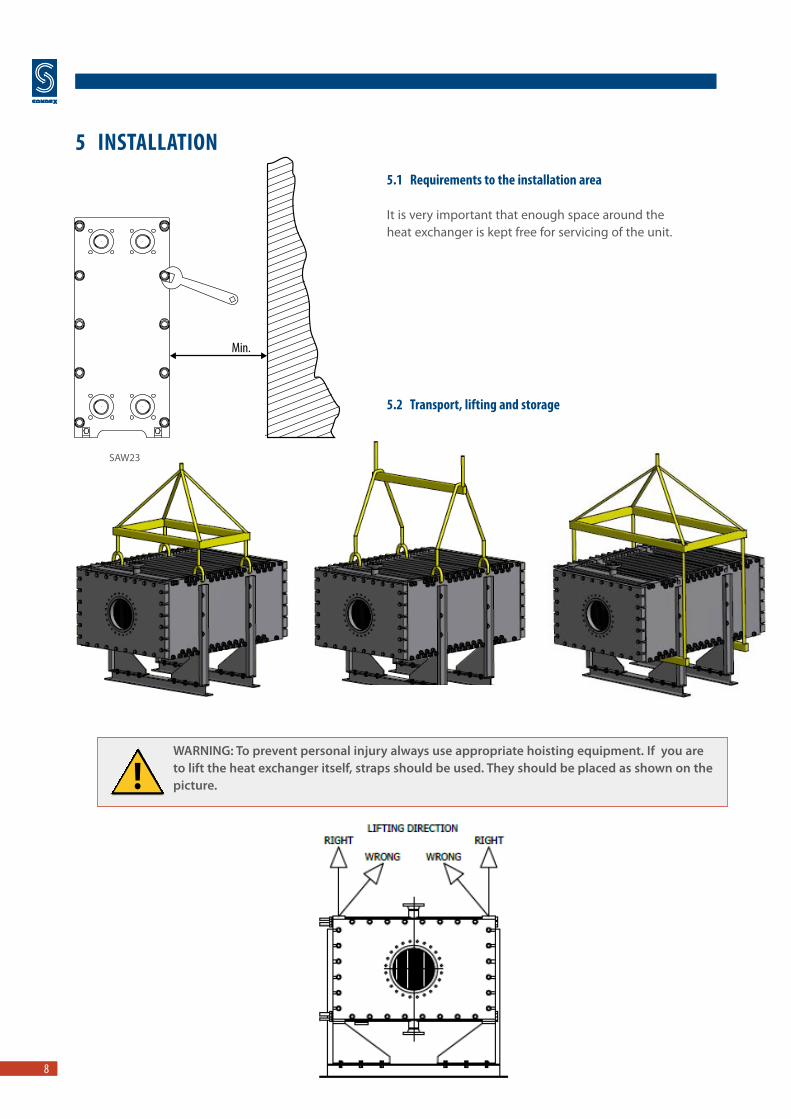
5.1 Requirements to the installation area
It is very important that enough space around the heat exchanger is kept free for servicing of the unit.
5.2 Transport, lifting and storage
5 INSTALLATION
WARNING: To prevent personal injury always use appropriate hoisting equipment. If you are to lift the heat exchanger itself, straps should be used. They should be placed as shown on the picture.
SAW23

9 9
Never lift the heat exchanger by using the connections or studs around them!
Attention:
ALWAYS: Use the lifting eyes (if fitted) Attach the straps to the clamping bolts
NEVER: Lift using the connections
Storage:Should it be necessary to store the heat exchanger for a longer period (1 month or more), certain precautions should be taken in order to prevent unnecessary damage to the equipment.
Preferably the heat exchanger should be stored inside in a room with a temperature around 15 to 20°C and a humidity of max. 70%.If this is not possible, place the heat exchanger in a wooden box which is provided with a lining on the inside against penetration of moisture.
5.3 Installing the pipe connectionsDepending on the type the SONDEX plate type heat exchanger will be provided with flanges, couplings, threaded pipes, etc.
When connecting the pipe system to the heat exchanger make sure that no stress or strain is imposed, by the pipe system, on to the heat exchanger!
We advise you of the following:• Heavy pipe work needs to be supported. This will prevent heavy forces on the heat
exchanger. • Always install flexible connections to prevent vibrations on the heat exchanger. These
flexible connections also prevent expansion of the pipe work, caused by temperature influence, onto the heat exchanger.
• These flexible connections need to be fitted in a longitudinal direction to the plate package.• The pipe work needs to be thoroughly cleaned and flushed before connecting up to the
heat exchanger.• Always install vents on both sides of the heat exchanger.
Note: For proper venting the vents should be fitted on the highest point in the direction of the flow of the medium (preferably on an air vessel). To enable the heat exchanger to be opened when necessary shut off valves should be provided in all connections!
Make sure that the pipe work, connected to the heat exchanger, is secured against pressure peaks / surges and temperature shocks!
10 10
6.1 Commissioning and pre-checksCommissioning may only be done by staff specially trained for the job or by SONDEX commissioning engineers.
Control, maintenance and repair of the installation may only be done by authorized, trained and properly instructed staff.
Maintenance and cleaning may only be done with a heat exchanger cooled to under 40° C and shut down!
Check if all connections are fitted correctly (see also 5.3).
Check the pressures and temperatures of the media and make sure that these are not more than the values specified on the name plate.
Cause of the many pressure holding weldings, it is important to heat up the heat exchanger slowly. The heating up time may not exceed 10°C / 15 minutes, when the heat exchanger has exceeded 50°C. Working pressure is to be achieved gradually max. 1 bar/min.
It is essential that the heat exchanger is not subjected to thermal or mechanical shock as this could lead to premature gasket failure
6.2 Operation
Start cold circuit first, then the hot circuit.
Fully vent the system;• Close shut off valve fitted between pump and exchanger;• Fully open valve fitted into return line from the exchanger;• Start the circulation pump normally placed by the inlet;• Gradually open closed shut off valve between pump and exchanger;• Vent system again if necessary.
Repeat the above for the secondary circuit.
6 COMMISSIONING / OPERATION

11 11
When using steam as one of the media:Use slow acting steam control valves and open slowly shut off valves!Before start up:• Ensure that the steam control valve is fully closed• Ensure that the heat exchanger is fully drained of condensate• Start cold circuit first, then the steam side• Open steam control valve slowly – this prevents water hammer of any condensate in the
steam line and reduces the pressure / thermal shock to the exchanger• Ensure that the steam trap is correctly sized to allow full condensate discharge – this
prevents water clogging inside the exchanger
Check for proper operation:• Check for pressure pulses in the system caused by the pumps or control valves. If found,
stop operation and rectify. Continuous pressure pulses will result in fatigue failure of the heat exchanger.
• Visually check the unit for leakages.• Check that all vents are closed to prevent air being sucked into the system.
When in operation, the conditions should not be changed. The max. conditions specified on the name plate should not be exceeded.
6.3 Shut-down for a short periodIf the heat exchanger has to be shut down for a short period, please follow this procedure:• Slowly close the control valve in the hot circuit whilst maintaining the full flow
in the cold circuit;• Switch off the hot circuit pump;• Cool down the heat exchanger to under 40°C;• Slowly close the control valve in the cold circuit;• Switch off the cold circuit pump;• Close all remaining shut off valves.
6.4 Shut-down for a long periodIf the unit is to be taken off line for an extended period of time then the following procedure should be followed:Point 6.3 must be followed, then:• Allow unit to cool down• Drain all circuits
Please also see chapter 5.2 - Storage
12 12
7.1 Clean in place (CIP)CIP cleaning (clean in place by circulating cleaning detergents)
To use CIP cleaning, it is a condition that the scaling on the plates is soluble. All materials in the whole circulation system of course have to be resistant to the cleaning detergent.
We advise you to ask for a confirmation from the supplier of the cleaning detergent that it will not damage the materials in the heat exchanger.
If the solution requires recirculation, select a flow that is as high as possible, andcertainly no less than the service or product flows.
Follow the instructions as given by the detergent supplier / cleaning specialist.We suggest that for recirculated cleaning detergent methods, the fluid should be pumped through the exchanger for no less than 30 minutes, but this is only an estimate, the cleaning time depends on the type of fouling.
RinsingAfter using any type of cleaning agent, always rinse thoroughly with fresh water. If cleaning in place then circulate fresh water for at least 10 minutes.
7.2 Some Cleaning DetergentsOil and grease can be removed with a water emulsifying oil solvent i.e. BP system.
Organic and grease cover can be removed with sodium hydroxide (NaOH) maximum concentration 1,5% - max. temp. 85°C. Mixture for 1,5% concentration = 5 ltr. 30% NaOH per 100 ltr. water.
Stone and limestone can be removed with nitric acid (HNO3) - max. concentration 1,5 % - max. temp. 65°C.Mixture for 1,5% concentration = 2.4 ltr. HNO3 62% per 100 ltr. water.Nitric acid also has an affective build up effect on the passivation film of stainless steel!
CAUTION: Nitric acid and Sodium Hydroxide may cause injury to exposed skin, eyes, and mucous membranes. Use of protective eyewear and gloves is strongly recommended.
7.3 Maintenance of the heat exchangerTime interval – once a year as a minimum• Check temperatures and flows against commissioning data.• Check general condition and look for any signs of leakage.• Wipe clean all painted parts and check surfaces for signs of damage
– “touch up” if necessary.• Check bolts and bars for rust and clean. Lightly coat threaded parts with molybdenum
grease or a corrosion inhibitor (ensure that no grease, etc. falls onto the plate gaskets.
7 MAINTENANCE

13 13
If you have problems with your heat exchanger, in most cases these can be solved by your own personnel. Please find below a summary of possible problems as well as possible causes and solutions.
A condition for the continuous proper functioning of your heat exchanger is in strict compliance with the permissible values for pressure and temperature mentioned on the name plate.Exceeding these values, even as short-lasting pressure peaks will causedamage to the unit and be the cause of problems. To avoid costly repairs, we advise you to have the installation work and maintenance carried out by properly trained personnel. You can also contact relevant SONDEX Sales Office.
8 PROBLEM SOLVING
Problem Possible Cause Possible Solution
Leakage At the connections • Check the flange gasket (if fitted)• Check the O-ring• Fit the pipes tension-free
Mixing of primary and secondary circuit
• Please contact Sondex
Insufficient capacity
Air in the system • De-aerate the pipe system• Check the pipe work for possible
air traps
The operating conditions deviate from the specification
• Adjust the operating conditions
The heat exchanger is dirty • Clean the heat exchanger
The connections have been interchanged
• Redo the pipe work
Flow larger the the design flow • Adjust the flow
Channels in plate(s) blocked • Flush /clean
Too high pressure drop
Incorrect measurements • Check the pressure indicator
Medium deviating from the design
• Addition of for instance anti-freeze will increase the pressure drop
Air in the system • De-aerate the pipe system• Check the pipe work for possible
air traps

Sondex A/S - Head OfficeJernet 9DK-6000 KoldingDenmarkTel.: +45 76 306 100Fax (1) +45 75 538 968Fax (2) +45 75 505 [email protected] www.sondex.net