operation and maintenance manual - holt of california · manual c4.4 industrial engine 4481-up...
TRANSCRIPT
SEBU8606-01May 2011
Operation andMaintenanceManualC4.4 Industrial Engine4481-Up (Engine)
SAFETY.CAT.COM

i03991620
Important Safety InformationMost accidents that involve product operation, maintenance and repair are caused by failure to observebasic safety rules or precautions. An accident can often be avoided by recognizing potentially hazardoussituations before an accident occurs. A person must be alert to potential hazards. This person should alsohave the necessary training, skills and tools to perform these functions properly.
Improper operation, lubrication, maintenance or repair of this product can be dangerous andcould result in injury or death.Do not operate or perform any lubrication, maintenance or repair on this product, until you haveread and understood the operation, lubrication, maintenance and repair information.Safety precautions and warnings are provided in this manual and on the product. If these hazard warningsare not heeded, bodily injury or death could occur to you or to other persons.
The hazards are identified by the “Safety Alert Symbol” and followed by a “Signal Word” such as“DANGER”, “WARNING” or “CAUTION”. The Safety Alert “WARNING” label is shown below.
The meaning of this safety alert symbol is as follows:
Attention! Become Alert! Your Safety is Involved.The message that appears under the warning explains the hazard and can be either written or pictoriallypresented.
A non-exhaustive list of operations that may cause product damage are identified by “NOTICE” labelson the product and in this publication.
Caterpillar cannot anticipate every possible circumstance that might involve a potential hazard.The warnings in this publication and on the product are, therefore, not all inclusive. You mustnot use this product in any manner different from that considered by this manual without firstsatisfying yourself that you have considered all safety rules and precautions applicable to theoperation of the product in the location of use, including site-specific rules and precautionsapplicable to the worksite. If a tool, procedure, work method or operating technique that is notspecifically recommended by Caterpillar is used, you must satisfy yourself that it is safe for youand for others. You should also ensure that the product will not be damaged or become unsafe bythe operation, lubrication, maintenance or repair procedures that you intend to use.The information, specifications, and illustrations in this publication are on the basis of information thatwas available at the time that the publication was written. The specifications, torques, pressures,measurements, adjustments, illustrations, and other items can change at any time. These changes canaffect the service that is given to the product. Obtain the complete and most current information before youstart any job. Cat dealers have the most current information available.
When replacement parts are required for thisproduct Caterpillar recommends using Cat re-placement parts or parts with equivalent speci-fications including, but not limited to, physicaldimensions, type, strength and material.
Failure to heed this warning can lead to prema-ture failures, product damage, personal injury ordeath.
In the United States, the maintenance, replacement, or repair of the emission control devices andsystems may be performed by any repair establishment or individual of the owner's choosing.
SEBU8606-01 3Table of Contents
Table of Contents
Foreword ................................................................. 4
Safety Section
Safety Messages .................................................... 6
General Hazard Information ................................... 8
Burn Prevention ..................................................... 11
Fire Prevention and Explosion Prevention ............ 12
Crushing Prevention and Cutting Prevention ........ 14
Mounting and Dismounting ................................... 15
High Pressure Fuel Lines ..................................... 15
Before Starting Engine .......................................... 16
Engine Starting ..................................................... 17
Engine Stopping ................................................... 17
Electrical System .................................................. 17
Engine Electronics ................................................ 18
Product Information Section
Model Views ......................................................... 20
Product Identification Information ........................ 29
Operation Section
Lifting and Storage ................................................ 31
Gauges and Indicators .......................................... 34
Features and Controls .......................................... 36
Engine Diagnostics ............................................... 46
Engine Starting ..................................................... 52
Engine Operation .................................................. 55
Engine Stopping ................................................... 57
Cold Weather Operation ....................................... 59
Maintenance Section
Refill Capacities .................................................... 64
Maintenance Recommendations .......................... 70
Maintenance Interval Schedule ............................ 72
Warranty Section
Warranty Information ........................................... 112
Reference Information Section
Engine Ratings .................................................... 113
Customer Service ................................................ 114
Reference Materials ............................................. 116
Index Section
Index .................................................................... 119
4 SEBU8606-01Foreword
ForewordLiterature InformationThis manual contains safety, operation instructions,lubrication and maintenance information. Thismanual should be stored in or near the engine areain a literature holder or literature storage area. Read,study and keep it with the literature and engineinformation.
English is the primary language for all Caterpillarpublications. The English used facilitates translationand consistency in electronic media delivery.
Some photographs or illustrations in this manualshow details or attachments that may be differentfrom your engine. Guards and covers may havebeen removed for illustrative purposes. Continuingimprovement and advancement of product designmay have caused changes to your engine which arenot included in this manual. Whenever a questionarises regarding your engine, or this manual, pleaseconsult with your Caterpillar dealer for the latestavailable information.
SafetyThis safety section lists basic safety precautions.In addition, this section identifies hazardous,warning situations. Read and understand the basicprecautions listed in the safety section beforeoperating or performing lubrication, maintenance andrepair on this product.
OperationOperating techniques outlined in this manual arebasic. They assist with developing the skills andtechniques required to operate the engine moreefficiently and economically. Skill and techniquesdevelop as the operator gains knowledge of theengine and its capabilities.
The operation section is a reference for operators.Photographs and illustrations guide the operatorthrough procedures of inspecting, starting, operatingand stopping the engine. This section also includes adiscussion of electronic diagnostic information.
MaintenanceThe maintenance section is a guide to engine care.The illustrated, step-by-step instructions are groupedby fuel consumption, service hours and/or calendartime maintenance intervals. Items in the maintenanceschedule are referenced to detailed instructions thatfollow.
Use fuel consumption or service hours to determineintervals. Calendar intervals shown (daily, annually,etc.) may be used instead of service meter intervalsif they provide more convenient schedules andapproximate the indicated service meter reading.
Recommended service should be performed at theappropriate intervals as indicated in the MaintenanceInterval Schedule. The actual operating environmentof the engine also governs the Maintenance IntervalSchedule. Therefore, under extremely severe,dusty, wet or freezing cold operating conditions,more frequent lubrication and maintenance than isspecified in the Maintenance Interval Schedule maybe necessary.
The maintenance schedule items are organized fora preventive maintenance management program. Ifthe preventive maintenance program is followed, aperiodic tune-up is not required. The implementationof a preventive maintenance management programshould minimize operating costs through costavoidances resulting from reductions in unscheduleddowntime and failures.
Maintenance IntervalsPerform maintenance on items at multiples of theoriginal requirement. Each level and/or individualitems in each level should be shifted ahead or backdepending upon your specific maintenance practices,operation and application. We recommend thatthe maintenance schedules be reproduced anddisplayed near the engine as a convenient reminder.We also recommend that a maintenance record bemaintained as part of the engine's permanent record.
See the section in the Operation and MaintenanceManual, “Maintenance Records” for informationregarding documents that are generally acceptedas proof of maintenance or repair. Your authorizedCaterpillar dealer can assist you in adjusting yourmaintenance schedule to meet the needs of youroperating environment.
OverhaulMajor engine overhaul details are not covered in theOperation and Maintenance Manual except for theinterval and the maintenance items in that interval.Major repairs are best left to trained personnel oran authorized Caterpillar dealer. Your Caterpillardealer offers a variety of options regarding overhaulprograms. If you experience a major engine failure,there are also numerous after failure overhaul optionsavailable from your Caterpillar dealer. Consult withyour dealer for information regarding these options.

SEBU8606-01 5Foreword
California Proposition 65 WarningDiesel engine exhaust and some of its constituentsare known to the State of California to cause cancer,birth defects, and other reproductive harm.
Battery posts, terminals and related accessoriescontain lead and lead compounds. Wash handsafter handling.

6 SEBU8606-01Safety SectionSafety Messages
Safety Sectioni04245489
Safety MessagesSMCS Code: 1000; 7405
There may be several specific warning signs on yourengine. The exact location and a description of thewarning signs are reviewed in this section. Pleasebecome familiar with all warning signs.
Ensure that all of the warning signs are legible. Cleanthe warning signs or replace the warning signs ifthe words cannot be read or if the illustrations arenot visible. Use a cloth, water, and soap to cleanthe warning signs. Do not use solvents, gasoline, orother harsh chemicals. Solvents, gasoline, or harshchemicals could loosen the adhesive that secures thewarning signs. The warning signs that are loosenedcould drop off the engine.
Replace any warning sign that is damaged ormissing. If a warning sign is attached to a part of theengine that is replaced, install a new warning sign onthe replacement part. Your Caterpillar distributor canprovide new warning signs.
(1) Universal Warning
Do not operate or work on this equipment unlessyou have read and understand the instructionsand warnings in the Operation and MaintenanceManuals. Failure to follow the instructions orheed the warnings could result in serious injuryor death.
g01154807Illustration 1
Typical example
The Universal Warning label (1) is located in twopositions. The warning labels are located on the rearright side of the valve mechanism cover and locatedon the crankcase breather body.
SEBU8606-01 7Safety Section
Safety Messages
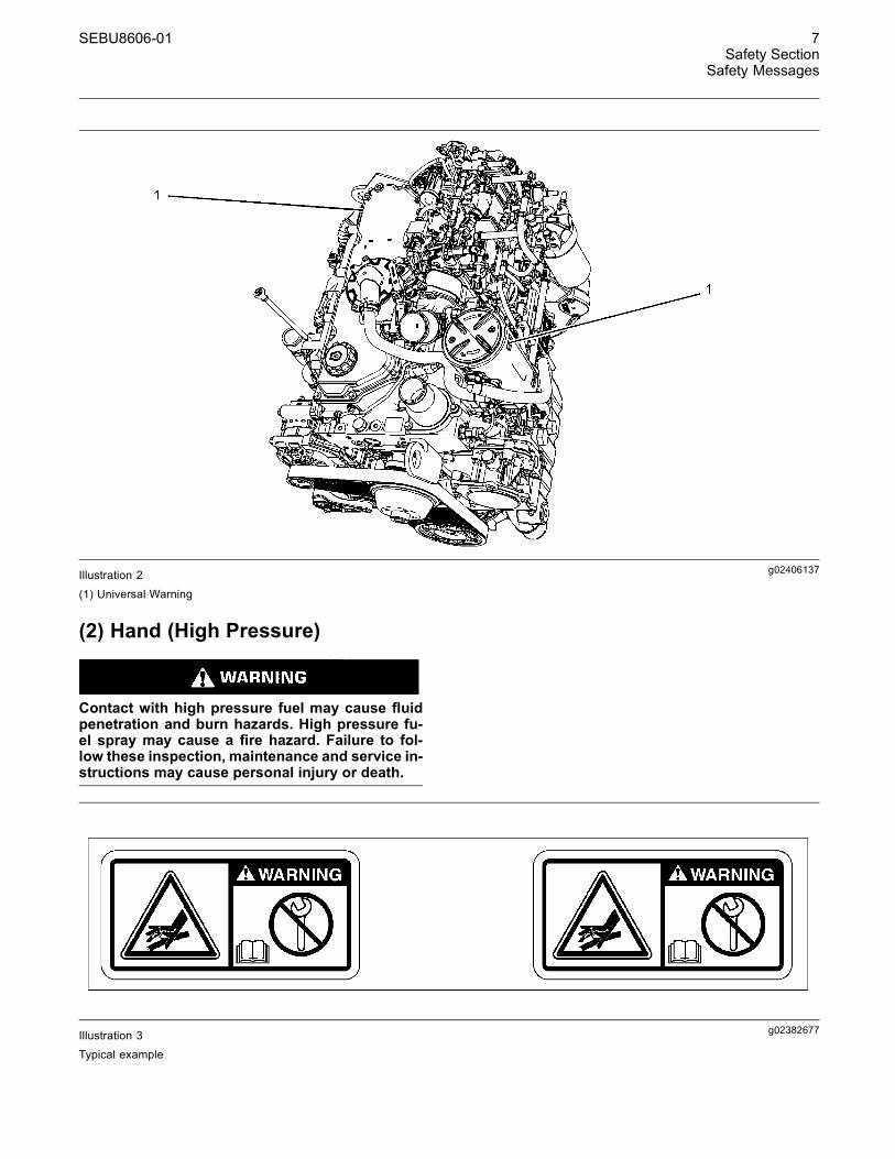
g02406137Illustration 2
(1) Universal Warning
(2) Hand (High Pressure)
Contact with high pressure fuel may cause fluidpenetration and burn hazards. High pressure fu-el spray may cause a fire hazard. Failure to fol-low these inspection, maintenance and service in-structions may cause personal injury or death.
g02382677Illustration 3Typical example
8 SEBU8606-01Safety SectionGeneral Hazard Information
g02406178Illustration 4
(2) Hand (High Pressure)
The warning label for the Hand (High Pressure)(2) is a wrap around label that is installed on thehigh-pressure fuel line.
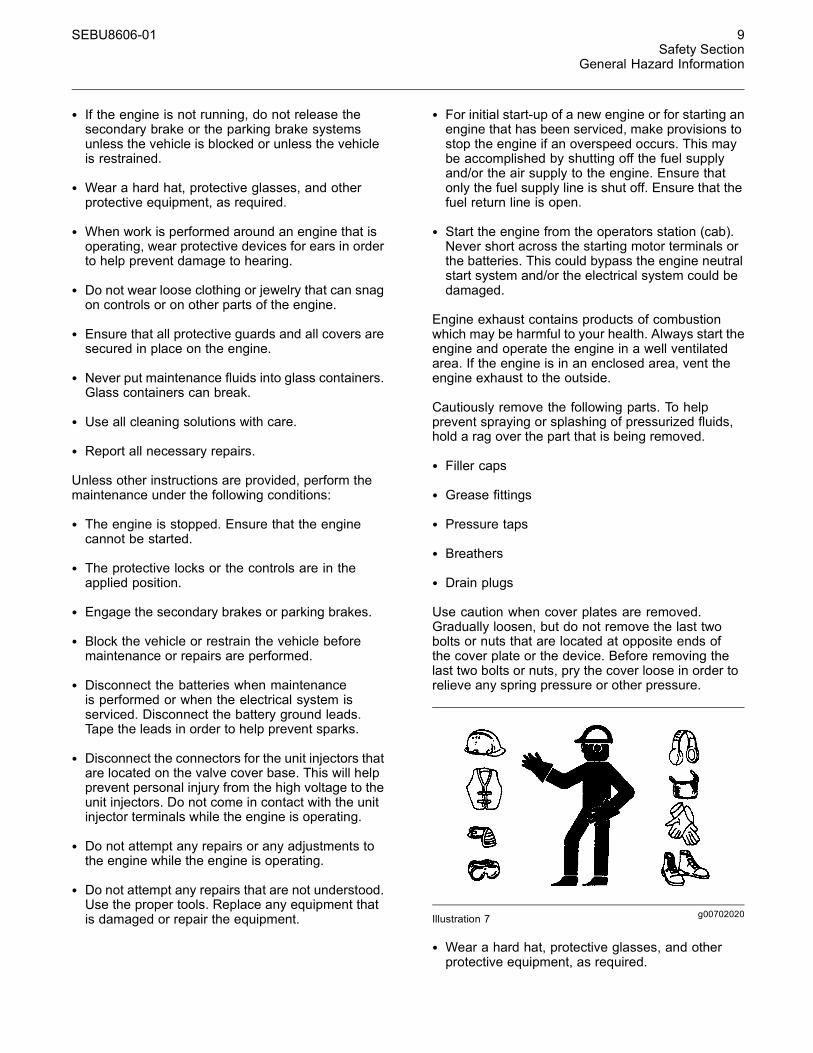
Ether WarningAn ether warning label will be installed on the aircleaner or close to the air cleaner. The location willdepend on the application.
Do not operate or work on this equipment unlessyou have read and understand the instructionsand warnings in the Operation and MaintenanceManuals. Failure to follow the instructions orheed the warnings could result in serious injuryor death.
g01154809Illustration 5
i04261691
General Hazard InformationSMCS Code: 1000; 7405
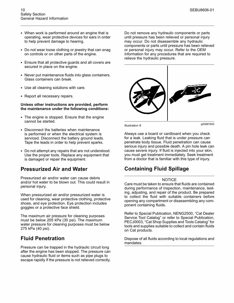
g00104545Illustration 6
Attach a “Do Not Operate” warning tag or a similarwarning tag to the start switch or to the controlsbefore the engine is serviced or before the engine isrepaired. These warning tags (Special Instruction,SEHS7332) are available from your Caterpillardealer. Attach the warning tags to the engine and toeach operator control station. When it is appropriate,disconnect the starting controls.
Do not allow unauthorized personnel on the engine,or around the engine when the engine is beingserviced.
• Tampering with the engine installation or tamperingwith the OEM supplied wiring can be dangerous.Personal injury, death and/or engine damage couldresult.
• Vent the engine exhaust to the outside when theengine is operated in an enclosed area.
SEBU8606-01 9Safety Section
General Hazard Information
• If the engine is not running, do not release thesecondary brake or the parking brake systemsunless the vehicle is blocked or unless the vehicleis restrained.
• Wear a hard hat, protective glasses, and otherprotective equipment, as required.
• When work is performed around an engine that isoperating, wear protective devices for ears in orderto help prevent damage to hearing.
• Do not wear loose clothing or jewelry that can snagon controls or on other parts of the engine.
• Ensure that all protective guards and all covers aresecured in place on the engine.
• Never put maintenance fluids into glass containers.Glass containers can break.
• Use all cleaning solutions with care.
• Report all necessary repairs.
Unless other instructions are provided, perform themaintenance under the following conditions:
• The engine is stopped. Ensure that the enginecannot be started.
• The protective locks or the controls are in theapplied position.
• Engage the secondary brakes or parking brakes.
• Block the vehicle or restrain the vehicle beforemaintenance or repairs are performed.
• Disconnect the batteries when maintenanceis performed or when the electrical system isserviced. Disconnect the battery ground leads.Tape the leads in order to help prevent sparks.
• Disconnect the connectors for the unit injectors thatare located on the valve cover base. This will helpprevent personal injury from the high voltage to theunit injectors. Do not come in contact with the unitinjector terminals while the engine is operating.
• Do not attempt any repairs or any adjustments tothe engine while the engine is operating.
• Do not attempt any repairs that are not understood.Use the proper tools. Replace any equipment thatis damaged or repair the equipment.
• For initial start-up of a new engine or for starting anengine that has been serviced, make provisions tostop the engine if an overspeed occurs. This maybe accomplished by shutting off the fuel supplyand/or the air supply to the engine. Ensure thatonly the fuel supply line is shut off. Ensure that thefuel return line is open.
• Start the engine from the operators station (cab).Never short across the starting motor terminals orthe batteries. This could bypass the engine neutralstart system and/or the electrical system could bedamaged.
Engine exhaust contains products of combustionwhich may be harmful to your health. Always start theengine and operate the engine in a well ventilatedarea. If the engine is in an enclosed area, vent theengine exhaust to the outside.
Cautiously remove the following parts. To helpprevent spraying or splashing of pressurized fluids,hold a rag over the part that is being removed.
• Filler caps
• Grease fittings
• Pressure taps
• Breathers
• Drain plugs
Use caution when cover plates are removed.Gradually loosen, but do not remove the last twobolts or nuts that are located at opposite ends ofthe cover plate or the device. Before removing thelast two bolts or nuts, pry the cover loose in order torelieve any spring pressure or other pressure.
g00702020Illustration 7
• Wear a hard hat, protective glasses, and otherprotective equipment, as required.
10 SEBU8606-01Safety SectionGeneral Hazard Information
• When work is performed around an engine that isoperating, wear protective devices for ears in orderto help prevent damage to hearing.
• Do not wear loose clothing or jewelry that can snagon controls or on other parts of the engine.
• Ensure that all protective guards and all covers aresecured in place on the engine.
• Never put maintenance fluids into glass containers.Glass containers can break.
• Use all cleaning solutions with care.
• Report all necessary repairs.
Unless other instructions are provided, performthe maintenance under the following conditions:
• The engine is stopped. Ensure that the enginecannot be started.
• Disconnect the batteries when maintenanceis performed or when the electrical system isserviced. Disconnect the battery ground leads.Tape the leads in order to help prevent sparks.
• Do not attempt any repairs that are not understood.Use the proper tools. Replace any equipment thatis damaged or repair the equipment.
Pressurized Air and WaterPressurized air and/or water can cause debrisand/or hot water to be blown out. This could result inpersonal injury.
When pressurized air and/or pressurized water isused for cleaning, wear protective clothing, protectiveshoes, and eye protection. Eye protection includesgoggles or a protective face shield.
The maximum air pressure for cleaning purposesmust be below 205 kPa (30 psi). The maximumwater pressure for cleaning purposes must be below275 kPa (40 psi).
Fluid PenetrationPressure can be trapped in the hydraulic circuit longafter the engine has been stopped. The pressure cancause hydraulic fluid or items such as pipe plugs toescape rapidly if the pressure is not relieved correctly.
Do not remove any hydraulic components or partsuntil pressure has been relieved or personal injurymay occur. Do not disassemble any hydrauliccomponents or parts until pressure has been relievedor personal injury may occur. Refer to the OEMinformation for any procedures that are required torelieve the hydraulic pressure.
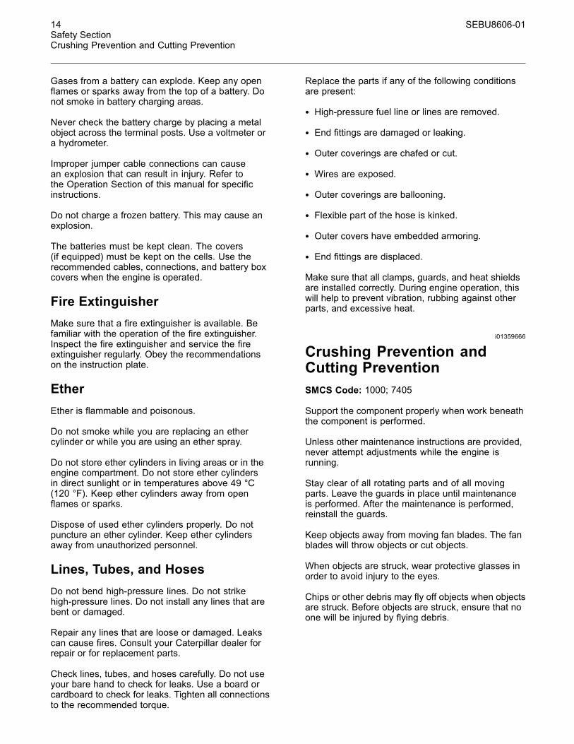
g00687600Illustration 8
Always use a board or cardboard when you checkfor a leak. Leaking fluid that is under pressure canpenetrate body tissue. Fluid penetration can causeserious injury and possible death. A pin hole leak cancause severe injury. If fluid is injected into your skin,you must get treatment immediately. Seek treatmentfrom a doctor that is familiar with this type of injury.
Containing Fluid Spillage
NOTICECare must be taken to ensure that fluids are containedduring performance of inspection, maintenance, test-ing, adjusting, and repair of the product. Be preparedto collect the fluid with suitable containers beforeopening any compartment or disassembling any com-ponent containing fluids.
Refer to Special Publication, NENG2500, “Cat DealerService Tool Catalog” or refer to Special Publication,PECJ0003, “Cat Shop Supplies and Tools Catalog” fortools and supplies suitable to collect and contain fluidson Cat products.
Dispose of all fluids according to local regulations andmandates.

SEBU8606-01 11Safety Section
Burn Prevention
Asbestos Information
g00702022Illustration 9
Caterpillar equipment and replacement parts that areshipped from Caterpillar are asbestos free. Caterpillarrecommends the use of only genuine Caterpillarreplacement parts. Use the following guidelineswhen you handle any replacement parts that containasbestos or when you handle asbestos debris.
Use caution. Avoid inhaling dust that might begenerated when you handle components that containasbestos fibers. Inhaling this dust can be hazardousto your health. The components that may containasbestos fibers are brake pads, brake bands, liningmaterial, clutch plates, and some gaskets. Theasbestos that is used in these components is usuallybound in a resin or sealed in some way. Normalhandling is not hazardous unless airborne dust thatcontains asbestos is generated.
If dust that may contain asbestos is present, thereare several guidelines that should be followed:
• Never use compressed air for cleaning.
• Avoid brushing materials that contain asbestos.
• Avoid grinding materials that contain asbestos.
• Use a wet method in order to clean up asbestosmaterials.
• A vacuum cleaner that is equipped with a highefficiency particulate air filter (HEPA) can also beused.
• Use exhaust ventilation on permanent machiningjobs.
• Wear an approved respirator if there is no otherway to control the dust.
• Comply with applicable rules and regulationsfor the work place. In the United States, useOccupational Safety and Health Administration(OSHA) requirements. These OSHA requirementscan be found in “29 CFR 1910.1001”.
• Obey environmental regulations for the disposalof asbestos.
• Stay away from areas that might have asbestosparticles in the air.
Dispose of Waste Properly
g00706404Illustration 10
Improperly disposing of waste can threaten theenvironment. Potentially harmful fluids should bedisposed of according to local regulations.
Always use leakproof containers when you drainfluids. Do not pour waste onto the ground, down adrain, or into any source of water.
i04246490
Burn PreventionSMCS Code: 1000; 7405
Do not touch any part of an operating enginesystem. The engine, the exhaust, and the engineaftertreatment system can reach temperatures ashigh as 650° C (1202° F) under normal operatingconditions.
Allow the engine system to cool before anymaintenance is performed. Relieve all pressure in theair system, hydraulic system, lubrication system, fuelsystem, and the cooling system before the relateditems are disconnected.

12 SEBU8606-01Safety SectionFire Prevention and Explosion Prevention
Contact with high pressure fuel may cause fluidpenetration and burn hazards. High pressure fu-el spray may cause a fire hazard. Failure to fol-low these inspection, maintenance and service in-structions may cause personal injury or death.
After the engine has stopped, you must wait for 10minutes in order to allow the fuel pressure to bepurged from the high-pressure fuel lines before anyservice or repair is performed on the engine fuel lines.
Allow the pressure to be purged in the air system, inthe hydraulic system, in the lubrication system, orin the cooling system before any lines, fittings, orrelated items are disconnected.
Induction System
Sulfuric Acid Burn Hazard may cause serious per-sonal injury or death.
The exhaust gas cooler may contain a smallamount of sulfuric acid. The use of fuel with sul-fur levels greater than 15 ppm may increase theamount of sulfuric acid formed. The sulfuric acidmay spill from the cooler during service of theengine. The sulfuric acid will burn the eyes, skinand clothing on contact. Always wear the appro-priate personal protective equipment (PPE) thatis noted on a material safety data sheet (MSDS)for sulfuric acid. Always follow the directions forfirst aid that are noted on a material safety datasheet (MSDS) for sulfuric acid.
CoolantWhen the engine is at operating temperature, theengine coolant is hot. The coolant is also underpressure. The radiator and all lines to the heaters orto the engine contain hot coolant.
Any contact with hot coolant or with steam can causesevere burns. Allow cooling system components tocool before the cooling system is drained.
Check that the coolant level after the engine hasstopped and the engine has been allowed to cool.
Ensure that the filler cap is cool before removing thefiller cap. The filler cap must be cool enough to touchwith a bare hand. Remove the filler cap slowly inorder to relieve pressure.
Cooling system conditioner contains alkali. Alkali cancause personal injury. Do not allow alkali to contactthe skin, the eyes, or the mouth.
OilsHot oil and hot lubricating components can causepersonal injury. Do not allow hot oil to contact theskin. Also, do not allow hot components to contactthe skin.
BatteriesElectrolyte is an acid. Electrolyte can cause personalinjury. Do not allow electrolyte to contact the skin orthe eyes. Always wear protective glasses for servicingbatteries. Wash hands after touching the batteriesand connectors. Use of gloves is recommended.
i04261710
Fire Prevention and ExplosionPreventionSMCS Code: 1000; 7405
g00704000Illustration 11
All fuels, most lubricants, and some coolant mixturesare flammable.
Flammable fluids that are leaking or spilled onto hotsurfaces or onto electrical components can causea fire. Fire may cause personal injury and propertydamage.
A flash fire may result if the covers for the enginecrankcase are removed within 15 minutes after anemergency shutdown.
Determine whether the engine will be operated in anenvironment that allows combustible gases to bedrawn into the air inlet system. These gases couldcause the engine to overspeed. Personal injury,property damage, or engine damage could result.

SEBU8606-01 13Safety Section
Fire Prevention and Explosion Prevention
If the application involves the presence of combustiblegases, consult your Caterpillar dealer for additionalinformation about suitable protection devices.
Remove all flammable materials such as fuel, oil, anddebris from the engine. Do not allow any flammablematerials to accumulate on the engine.
Store fuels and lubricants in properly markedcontainers away from unauthorized persons. Storeoily rags and any flammable materials in protectivecontainers. Do not smoke in areas that are used forstoring flammable materials.
Do not expose the engine to any flame.
Exhaust shields (if equipped) protect hot exhaustcomponents from oil or fuel spray in a case of a line,a tube, or a seal failure. Exhaust shields must beinstalled correctly.
Do not weld on lines or tanks that contain flammablefluids. Do not flame cut lines or tanks that containflammable fluid. Clean any such lines or tanksthoroughly with a nonflammable solvent prior towelding or flame cutting.
Wiring must be kept in good condition. All electricalwires must be properly routed and securely attached.Check all electrical wires daily. Repair any wiresthat are loose or frayed before you operate theengine. Clean all electrical connections and tightenall electrical connections.
Eliminate all wiring that is unattached or unnecessary.Do not use any wires or cables that are smaller thanthe recommended gauge. Do not bypass any fusesand/or circuit breakers.
Arcing or sparking could cause a fire. Secureconnections, recommended wiring, and properlymaintained battery cables will help to prevent arcingor sparking.
Contact with high pressure fuel may cause fluidpenetration and burn hazards. High pressure fu-el spray may cause a fire hazard. Failure to fol-low these inspection, maintenance and service in-structions may cause personal injury or death.
After the engine has stopped, you must wait for 10minutes in order to allow the fuel pressure to bepurged from the high-pressure fuel lines before anyservice or repair is performed on the engine fuel lines.
Inspect all lines and hoses for wear or fordeterioration. The hoses must be properly routed.The lines and hoses must have adequate supportand secure clamps. Tighten all connections to therecommended torque. Leaks can cause fires.
Oil filters and fuel filters must be properly installed.The filter housings must be tightened to the propertorque.
g00704059Illustration 12
Use caution when you are refueling an engine. Donot smoke while you are refueling an engine. Do notrefuel an engine near open flames or sparks. Alwaysstop the engine before refueling.
g00704135Illustration 13
14 SEBU8606-01Safety SectionCrushing Prevention and Cutting Prevention
Gases from a battery can explode. Keep any openflames or sparks away from the top of a battery. Donot smoke in battery charging areas.
Never check the battery charge by placing a metalobject across the terminal posts. Use a voltmeter ora hydrometer.
Improper jumper cable connections can causean explosion that can result in injury. Refer tothe Operation Section of this manual for specificinstructions.
Do not charge a frozen battery. This may cause anexplosion.
The batteries must be kept clean. The covers(if equipped) must be kept on the cells. Use therecommended cables, connections, and battery boxcovers when the engine is operated.
Fire ExtinguisherMake sure that a fire extinguisher is available. Befamiliar with the operation of the fire extinguisher.Inspect the fire extinguisher and service the fireextinguisher regularly. Obey the recommendationson the instruction plate.
EtherEther is flammable and poisonous.
Do not smoke while you are replacing an ethercylinder or while you are using an ether spray.
Do not store ether cylinders in living areas or in theengine compartment. Do not store ether cylindersin direct sunlight or in temperatures above 49 °C(120 °F). Keep ether cylinders away from openflames or sparks.
Dispose of used ether cylinders properly. Do notpuncture an ether cylinder. Keep ether cylindersaway from unauthorized personnel.
Lines, Tubes, and HosesDo not bend high-pressure lines. Do not strikehigh-pressure lines. Do not install any lines that arebent or damaged.
Repair any lines that are loose or damaged. Leakscan cause fires. Consult your Caterpillar dealer forrepair or for replacement parts.
Check lines, tubes, and hoses carefully. Do not useyour bare hand to check for leaks. Use a board orcardboard to check for leaks. Tighten all connectionsto the recommended torque.
Replace the parts if any of the following conditionsare present:
• High-pressure fuel line or lines are removed.
• End fittings are damaged or leaking.
• Outer coverings are chafed or cut.
• Wires are exposed.
• Outer coverings are ballooning.
• Flexible part of the hose is kinked.
• Outer covers have embedded armoring.
• End fittings are displaced.
Make sure that all clamps, guards, and heat shieldsare installed correctly. During engine operation, thiswill help to prevent vibration, rubbing against otherparts, and excessive heat.
i01359666
Crushing Prevention andCutting PreventionSMCS Code: 1000; 7405
Support the component properly when work beneaththe component is performed.
Unless other maintenance instructions are provided,never attempt adjustments while the engine isrunning.
Stay clear of all rotating parts and of all movingparts. Leave the guards in place until maintenanceis performed. After the maintenance is performed,reinstall the guards.
Keep objects away from moving fan blades. The fanblades will throw objects or cut objects.
When objects are struck, wear protective glasses inorder to avoid injury to the eyes.
Chips or other debris may fly off objects when objectsare struck. Before objects are struck, ensure that noone will be injured by flying debris.
SEBU8606-01 15Safety Section
Mounting and Dismounting
i04016709
Mounting and DismountingSMCS Code: 1000; 7405
Do not climb on the engine or the engineaftertreatment. The engine and aftertreatment havenot been designed with mounting or dismountinglocations.
Refer to the OEM for the location of foot and handholds for your specific application.
i03814031
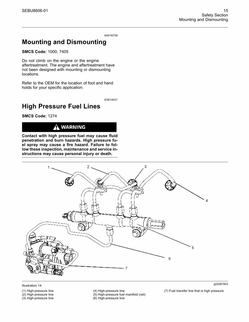
High Pressure Fuel LinesSMCS Code: 1274
Contact with high pressure fuel may cause fluidpenetration and burn hazards. High pressure fu-el spray may cause a fire hazard. Failure to fol-low these inspection, maintenance and service in-structions may cause personal injury or death.
g02067853Illustration 14
(1) High-pressure line(2) High-pressure line(3) High-pressure line
(4) High-pressure line(5) High-pressure fuel manifold (rail)(6) High-pressure line
(7) Fuel transfer line that is high pressure

16 SEBU8606-01Safety SectionBefore Starting Engine
The high-pressure fuel lines are the fuel lines thatare between the high-pressure fuel pump and thehigh-pressure fuel manifold and the fuel lines that arebetween the fuel manifold and cylinder head. Thesefuel lines are different from fuel lines on other fuelsystems.
These differences are because of the following items:
• The high-pressure fuel lines are constantly chargedwith high pressure.
• The internal pressures of the high-pressure fuellines are higher than other types of fuel system.
• The high-pressure fuel lines are formed to shapeand then strengthened by a special process.
Do not step on the high-pressure fuel lines. Do notdeflect the high-pressure fuel lines. Do not bend orstrike the high-pressure fuel lines. Deformation ordamage of the high-pressure fuel lines may cause apoint of weakness and potential failure.
Do not check the high-pressure fuel lines with theengine or the starting motor in operation. After theengine has stopped wait 10 minutes in order to allowthe fuel pressure to be purged from the high-pressurefuel lines. before any service or repair is performed.
Do not loosen the high-pressure fuel lines in orderto remove air from the fuel system. This procedureis not required.
Visually inspect the high-pressure fuel lines beforethe engine is started. This inspection should be eachday.
If you inspect the engine in operation, always usethe proper inspection procedure in order to avoida fluid penetration hazard. Refer to Operation andMaintenance Manual, “General hazard Information”.
• Inspect the high-pressure fuel lines for damage,deformation, a nick, a cut, a crease, or a dent.
• Do not operate the engine with a fuel leak. If thereis a leak, do not tighten the connection in orderto stop the leak. The connection must only betightened to the recommended torque. Refer toDisassembly and Assembly, “Fuel injection lines -Remove and Fuel injection lines - Install”.
• If the high-pressure fuel lines are torqued correctly,and the high-pressure fuel lines are leaking thehigh-pressure fuel lines must be replaced.
• Ensure that all clips on the high-pressure fuel linesare in place. Do not operate the engine with clipsthat are damaged, missing, or loose.
• Do not attach any other item to the high-pressurefuel lines.
• Loosened high-pressure fuel lines must bereplaced. Also removed high-pressure fuel linesmust be replaced. Refer to Disassembly andAssembly manual, “ Fuel Injection Lines - Install”.
i03560601
Before Starting EngineSMCS Code: 1000
NOTICEFor initial start-up of a new or rebuilt engine, and forstart-up of an engine that has been serviced, makeprovision to shut the engine off should an overspeedoccur. This may be accomplished by shutting off theair and/or fuel supply to the engine.
Engine exhaust contains products of combustionwhich may be harmful to your health. Always startand operate the engine in a well ventilated areaand, if in an enclosed area, vent the exhaust to theoutside.
Inspect the engine for potential hazards.
Do not start the engine or move any of the controlsif there is a “DO NOT OPERATE” warning tag orsimilar warning tag attached to the start switch or tothe controls.
Before starting the engine, ensure that no one is on,underneath, or close to the engine. Ensure that thearea is free of personnel.
If equipped, ensure that the lighting system for theengine is suitable for the conditions. Ensure that alllights work properly, if equipped.
All protective guards and all protective covers mustbe installed if the engine must be started in orderto perform service procedures. To help prevent anaccident that is caused by parts in rotation, workaround the parts carefully.
Do not bypass the automatic shutoff circuits. Do notdisable the automatic shutoff circuits. The circuits areprovided in order to help prevent personal injury. Thecircuits are also provided in order to help preventengine damage.
See the Service Manual for repairs and foradjustments.

SEBU8606-01 17Safety SectionEngine Starting
i03635086
Engine StartingSMCS Code: 1000
Do not use aerosol types of starting aids such asether. Such use could result in an explosion andpersonal injury.
If a warning tag is attached to the engine start switchor to the controls DO NOT start the engine or movethe controls. Consult with the person that attachedthe warning tag before the engine is started.
All protective guards and all protective covers mustbe installed if the engine must be started in orderto perform service procedures. To help prevent anaccident that is caused by parts in rotation, workaround the parts carefully.
Start the engine from the operator's compartment orfrom the engine start switch.
Always start the engine according to the procedurethat is described in the Operation and MaintenanceManual, “Engine Starting” topic in the OperationSection. Knowing the correct procedure will help toprevent major damage to the engine components.Knowing the procedure will also help to preventpersonal injury.
To ensure that the jacket water heater (if equipped)and/or the lube oil heater (if equipped) is workingcorrectly, check the water temperature gaugeand/or the oil temperature gauge during the heateroperation.
Engine exhaust contains products of combustionwhich can be harmful to your health. Always start theengine and operate the engine in a well ventilatedarea. If the engine is started in an enclosed area,vent the engine exhaust to the outside.
These engines are equipped with a glow plug startingaid in each individual cylinder that heats the intake airin order to improve starting. Some Caterpillar enginesmay have a cold starting system that is controlled bythe ECM that allows a controlled flow of ether intothe engine. The ECM will disconnect the glow plugsbefore the ether is introduced. This system wouldbe installed at the factory.
i03648639
Engine StoppingSMCS Code: 1000
To avoid overheating of the engine and acceleratedwear of the engine components, stop the engineaccording to this Operation and Maintenance Manual,“Engine Stopping” topic (Operation Section).
Use the Emergency Stop Button (if equipped)ONLY in an emergency situation. DO NOT use theEmergency Stop Button for normal engine stopping.After an emergency stop, DO NOT start the engineuntil the problem that caused the emergency stophas been corrected.
On the initial start-up of a new engine or an enginethat has been serviced, make provisions to stop theengine if an overspeed condition occurs.
i04231629
Electrical SystemSMCS Code: 1000; 1400
Never disconnect any charging unit circuit or batterycircuit cable from the battery when the charging unitis operating. A spark can cause the combustiblegases that are produced by some batteries to ignite.
To help prevent sparks from igniting combustiblegases that are produced by some batteries, thenegative “−” cable should be connected last fromthe external power source to the primary position forgrounding.
Check the electrical wires daily for wires thatare loose or frayed. Tighten all loose electricalconnections before the engine is started. Repair allfrayed electrical wires before the engine is started.See the Operation and Maintenance Manual forspecific starting instructions.
18 SEBU8606-01Safety SectionEngine Electronics
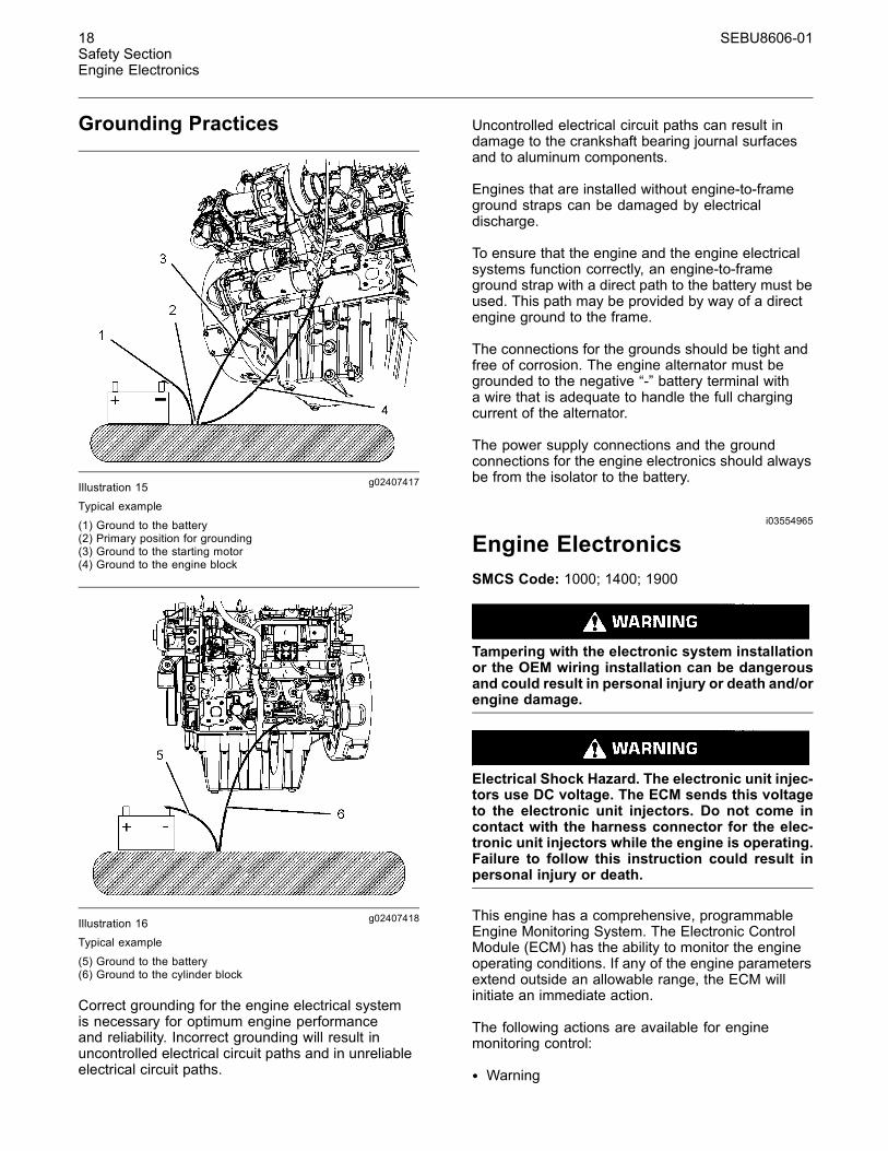
Grounding Practices
g02407417Illustration 15Typical example
(1) Ground to the battery(2) Primary position for grounding(3) Ground to the starting motor(4) Ground to the engine block
g02407418Illustration 16Typical example
(5) Ground to the battery(6) Ground to the cylinder block
Correct grounding for the engine electrical systemis necessary for optimum engine performanceand reliability. Incorrect grounding will result inuncontrolled electrical circuit paths and in unreliableelectrical circuit paths.
Uncontrolled electrical circuit paths can result indamage to the crankshaft bearing journal surfacesand to aluminum components.
Engines that are installed without engine-to-frameground straps can be damaged by electricaldischarge.
To ensure that the engine and the engine electricalsystems function correctly, an engine-to-frameground strap with a direct path to the battery must beused. This path may be provided by way of a directengine ground to the frame.
The connections for the grounds should be tight andfree of corrosion. The engine alternator must begrounded to the negative “-” battery terminal witha wire that is adequate to handle the full chargingcurrent of the alternator.
The power supply connections and the groundconnections for the engine electronics should alwaysbe from the isolator to the battery.
i03554965
Engine ElectronicsSMCS Code: 1000; 1400; 1900
Tampering with the electronic system installationor the OEM wiring installation can be dangerousand could result in personal injury or death and/orengine damage.
Electrical Shock Hazard. The electronic unit injec-tors use DC voltage. The ECM sends this voltageto the electronic unit injectors. Do not come incontact with the harness connector for the elec-tronic unit injectors while the engine is operating.Failure to follow this instruction could result inpersonal injury or death.
This engine has a comprehensive, programmableEngine Monitoring System. The Electronic ControlModule (ECM) has the ability to monitor the engineoperating conditions. If any of the engine parametersextend outside an allowable range, the ECM willinitiate an immediate action.
The following actions are available for enginemonitoring control:
• Warning

SEBU8606-01 19Safety Section
Engine Electronics
• Derate
• Shutdown
The following monitored engine operating conditionsand components have the ability to limit enginespeed and/or the engine power:
• Engine Coolant Temperature
• Engine Oil Pressure
• Engine Speed
• Intake Manifold Air Temperature
• Engine Intake Throttle Valve Fault
• Wastegate Regulator
• Supply Voltage to Sensors
• Fuel Pressure in Manifold (Rail)
• NOx Reduction System
• Engine Aftertreatment System
The Engine Monitoring package can vary for differentengine models and different engine applications.However, the monitoring system and the enginemonitoring control will be similar for all engines.
Note:Many of the engine control systems and displaymodules that are available for Caterpillar Engineswill work in unison with the Engine MonitoringSystem. Together, the two controls will provide theengine monitoring function for the specific engineapplication. Refer to the Troubleshooting for moreinformation on the Engine Monitoring System.

20 SEBU8606-01Product Information SectionModel Views
Product InformationSection
Model Viewsi04246230
Model View IllustrationsSMCS Code: 1000
The following model views show typical featuresof the engine and the aftertreatment system.Due to individual applications, your engine, andyour aftertreatment may appear different from theillustrations.
Series Turbocharger Arrangement
g02409511Illustration 17
(1) Front lifting eye(2) Crankcase breather(3) NOx Reduction system (NRS)(4) Primary fuel filter(5) Secondary fuel filter
(6) Electronic control module (ECM)(7) Fuel priming pump(8) Oil gauge (dipstick)(9) Fuel strainer(10) Oil filter
(11) Oil sampling valve(12) Oil filler(13) High-pressure fuel pump

SEBU8606-01 21Product Information Section
Model Views
g02409512Illustration 18
(14) Rear lifting eye(15) High-pressure turbocharger(16) Low-pressure turbocharger(17) Back pressure valve
(18) Starting motor(19) Oil drain plug(20) Exhaust outlet(21) Flywheel housing
(22) Flywheel(23) NRS cooler

22 SEBU8606-01Product Information SectionModel Views
g02409862Illustration 19
(24) Belt(25) Air intake(26) Coolant outlet connection
(27) Thermostat housing(28) Water pump(29) Coolant inlet connection
(30) Crankshaft pulley(31) Belt tensioner(32) Alternator

SEBU8606-01 23Product Information Section
Model Views
Engine with a Single Turbocharger
g02407436Illustration 20(1) Front lifting eye(2) Crankcase breather(3) NOx reduction system (NRS)(4) Secondary fuel filter
(5) Primary fuel filter(6) Fuel priming pump(7) Fuel strainer(8) Electronic control module (ECM)
(9) Oil filter(10) Oil sampling valve(11) High-pressure fuel pump
24 SEBU8606-01Product Information SectionModel Views
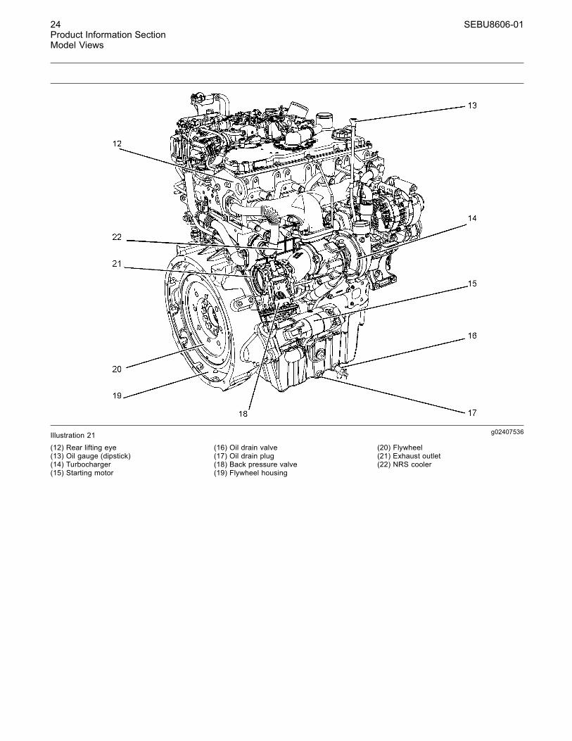
g02407536Illustration 21
(12) Rear lifting eye(13) Oil gauge (dipstick)(14) Turbocharger(15) Starting motor
(16) Oil drain valve(17) Oil drain plug(18) Back pressure valve(19) Flywheel housing
(20) Flywheel(21) Exhaust outlet(22) NRS cooler

SEBU8606-01 25Product Information Section
Model Views
g02407537Illustration 22
(23) Oil filler(24) Air intake(25) Coolant outlet connection(26) Thermostat housing
(27) Water pump(28) Coolant intake connector(29) Crankshaft pulley(30) Belt tensioner
(31) Alternator(32) Belt
26 SEBU8606-01Product Information SectionModel Views
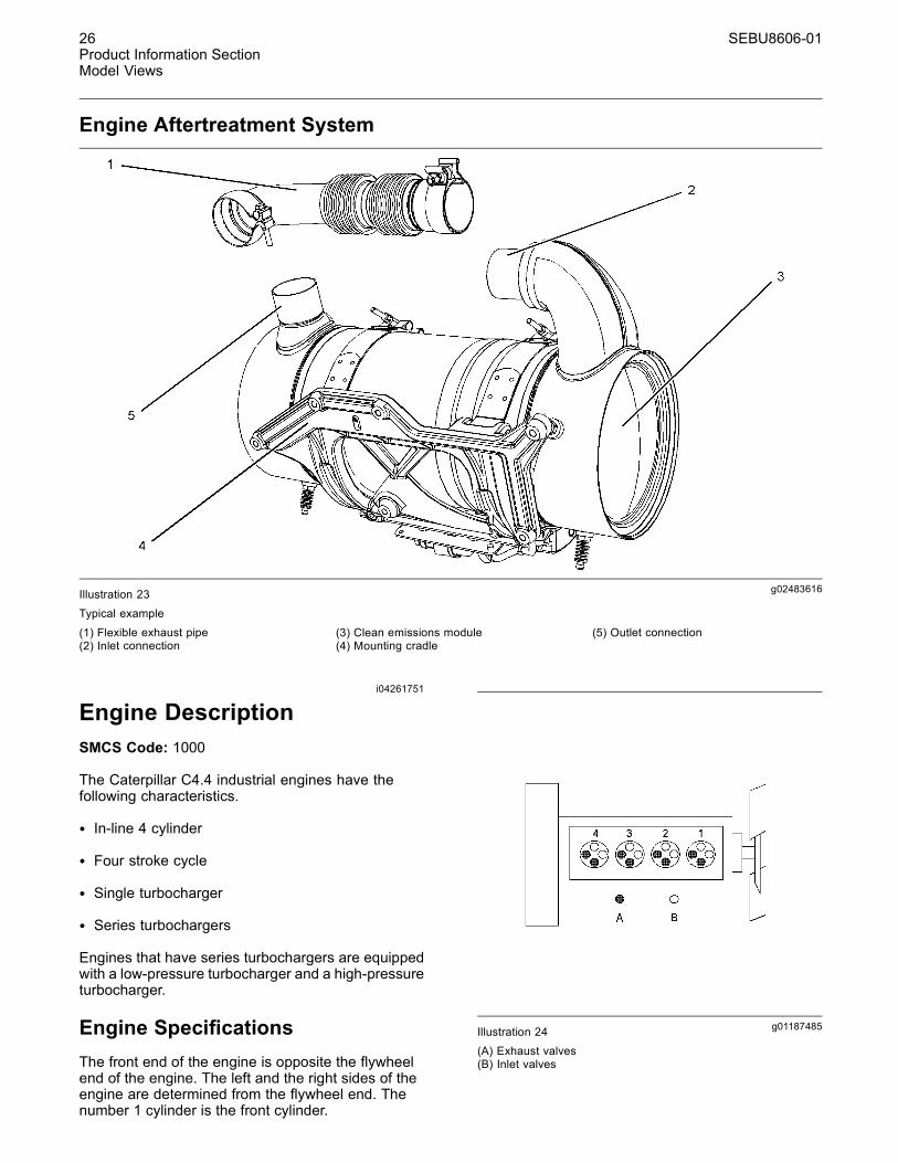
Engine Aftertreatment System
g02483616Illustration 23Typical example
(1) Flexible exhaust pipe(2) Inlet connection
(3) Clean emissions module(4) Mounting cradle
(5) Outlet connection
i04261751
Engine DescriptionSMCS Code: 1000
The Caterpillar C4.4 industrial engines have thefollowing characteristics.
• In-line 4 cylinder
• Four stroke cycle
• Single turbocharger
• Series turbochargers
Engines that have series turbochargers are equippedwith a low-pressure turbocharger and a high-pressureturbocharger.
Engine SpecificationsThe front end of the engine is opposite the flywheelend of the engine. The left and the right sides of theengine are determined from the flywheel end. Thenumber 1 cylinder is the front cylinder.
g01187485Illustration 24(A) Exhaust valves(B) Inlet valves
SEBU8606-01 27Product Information Section
Model Views
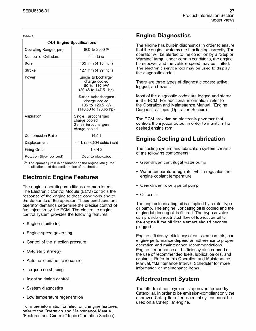
Table 1
C4.4 Engine Specifications
Operating Range (rpm) 800 to 2200 (1)
Number of Cylinders 4 In-Line
Bore 105 mm (4.13 inch)
Stroke 127 mm (4.99 inch)
Single turbochargercharge cooled60 to 110 kW
(80.46 to 147.51 hp)
Power
Series turbochargerscharge cooled105 to 129.5 kW
(140.80 to 173.65 hp)
Aspiration Single Turbochargedcharge cooledSeries turbochargerscharge cooled
Compression Ratio 16.5:1
Displacement 4.4 L (268.504 cubic inch)
Firing Order 1-3-4-2
Rotation (flywheel end) Counterclockwise(1) The operating rpm is dependent on the engine rating, theapplication, and the configuration of the throttle.
Electronic Engine FeaturesThe engine operating conditions are monitored.The Electronic Control Module (ECM) controls theresponse of the engine to these conditions and tothe demands of the operator. These conditions andoperator demands determine the precise control offuel injection by the ECM. The electronic enginecontrol system provides the following features:
• Engine monitoring
• Engine speed governing
• Control of the injection pressure
• Cold start strategy
• Automatic air/fuel ratio control
• Torque rise shaping
• Injection timing control
• System diagnostics
• Low temperature regeneration
For more information on electronic engine features,refer to the Operation and Maintenance Manual,“Features and Controls” topic (Operation Section).
Engine DiagnosticsThe engine has built-in diagnostics in order to ensurethat the engine systems are functioning correctly. Theoperator will be alerted to the condition by a “Stop orWarning” lamp. Under certain conditions, the enginehorsepower and the vehicle speed may be limited.The electronic service tool may be used to displaythe diagnostic codes.
There are three types of diagnostic codes: active,logged, and event.
Most of the diagnostic codes are logged and storedin the ECM. For additional information, refer tothe Operation and Maintenance Manual, “EngineDiagnostics” topic (Operation Section).
The ECM provides an electronic governor thatcontrols the injector output in order to maintain thedesired engine rpm.
Engine Cooling and LubricationThe cooling system and lubrication system consistsof the following components:
• Gear-driven centrifugal water pump
• Water temperature regulator which regulates theengine coolant temperature
• Gear-driven rotor type oil pump
• Oil cooler
The engine lubricating oil is supplied by a rotor typeoil pump. The engine lubricating oil is cooled and theengine lubricating oil is filtered. The bypass valvecan provide unrestricted flow of lubrication oil tothe engine if the oil filter element should becomeplugged.
Engine efficiency, efficiency of emission controls, andengine performance depend on adherence to properoperation and maintenance recommendations.Engine performance and efficiency also depend onthe use of recommended fuels, lubrication oils, andcoolants. Refer to this Operation and MaintenanceManual, “Maintenance Interval Schedule” for moreinformation on maintenance items.
Aftertreatment SystemThe aftertreatment system is approved for use byCaterpillar. In order to be emission-compliant only theapproved Caterpillar aftertreatment system must beused on a Caterpillar engine.
28 SEBU8606-01Product Information SectionModel Views
Clean Emission Module (CEM)
The CEM comprises of two main components in asingle unit, the Diesel Oxidation Catalyst DOC andthe Diesel Particulate Filter DPF. The function of theCEM is to ensure that the engine exhaust meetsthe required emissions regulation for the country ofoperation.
The engine exhaust is connected by a flexible pipe tothe CEM. The exhaust gases pass through the DOCin order to remove contaminants, carbon monoxide,and hydrocarbons. The exhaust gases then enter theDPF where any particulate matter soot and ash willbe trapped.
The CEM uses a passive regeneration process toensure that normal operation of the engine removesthe soot. The soot is removed at an equal rate ofwhich the soot is captured. The ash remains in theDPF and must be removed at an engine overhaul.
Engine Service LifeEngine efficiency and maximum utilization of engineperformance depend on the adherence to properoperation and maintenance recommendations. Inaddition, use recommended fuels, coolants, andlubricants. Use the Operation and MaintenanceManual as a guide for required engine maintenance.
Expected engine life is generally predicted by theaverage power that is demanded. The average powerthat is demanded is based on fuel consumption ofthe engine over a period of time. Reduced hours ofoperation at full throttle and/or operating at reducedthrottle settings result in a lower average powerdemand. Reduced hours of operation will increasethe length of operating time before an engineoverhaul is required.
Aftermarket Products andCaterpillar EnginesCaterpillar does not warrant the quality orperformance of non-Caterpillar fluids and filters.
When auxiliary devices, accessories, or consumables(filters, additives, catalysts, ) which are made by othermanufacturers are used on Caterpillar products, theCaterpillar warranty is not affected simply becauseof such use.
However, failures that result from the installationor use of other manufacturers devices,accessories, or consumables are NOT Caterpillardefects. Therefore, the defects are NOT coveredunder the Caterpillar warranty.
SEBU8606-01 29Product Information Section
Product Identification Information
Product IdentificationInformation
i03895545
Plate Locations and FilmLocationsSMCS Code: 1000
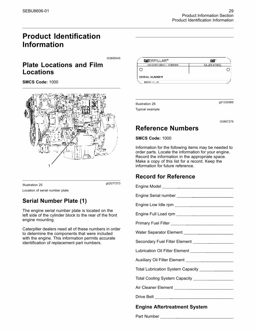
g02077373Illustration 25
Location of serial number plate
Serial Number Plate (1)The engine serial number plate is located on theleft side of the cylinder block to the rear of the frontengine mounting.
Caterpiller dealers need all of these numbers in orderto determine the components that were includedwith the engine. This information permits accurateidentification of replacement part numbers.
g01332986Illustration 26Typical example
i03867276
Reference NumbersSMCS Code: 1000
Information for the following items may be needed toorder parts. Locate the information for your engine.Record the information in the appropriate space.Make a copy of this list for a record. Keep theinformation for future reference.
Record for ReferenceEngine Model _______________________________________________
Engine Serial number _____________________________________
Engine Low Idle rpm ______________________________________
Engine Full Load rpm _____________________________________
Primary Fuel Filter _________________________________________
Water Separator Element ________________________________
Secondary Fuel Filter Element __________________________
Lubrication Oil Filter Element ___________________________
Auxiliary Oil Filter Element _______________________________
Total Lubrication System Capacity _____________________
Total Cooling System Capacity _________________________
Air Cleaner Element _______________________________________
Drive Belt ____________________________________________________
Engine Aftertreatment System
Part Number ________________________________________________

30 SEBU8606-01Product Information SectionProduct Identification Information
Serial Number ______________________________________________
i04274710
Emissions Certification FilmSMCS Code: 1000; 7405
The label for the emission is installed on the frontgear cover.
Note: A second emission label will be supplied withthe engine. If necessary, the second emission labelwill be installed on the application by the originalequipment manufacturer.
g02443539Illustration 27Typical example

SEBU8606-01 31Operation SectionLifting and Storage
Operation Section
Lifting and Storagei04195469
Product Lifting(Clean Emission Module)SMCS Code: 1000; 1404; 7002
g02385036Illustration 28
Ensure that the correct clothing is worn, refer tothis Operation and Maintenance Manual, “GeneralHazard Information”.
The weight of the clean emission module (CEM)when laden is approximately 50 kg (110 lb). Twosuitable double looped slings are required in order tolift the CEM. Also a suitable hoist will be required inorder to remove and install the assembly.
The slings must be attached to the CEM in thepositions as shown in illustration 28.
Ensure that the slings only contact the body of theCEM. A test lift may be required in order to achievethe correct balance of the assembly.
Some applications may require a frame or jig in orderto lift the CEM. A frame or jig must only be connectedto the cradle of the CEM. Refer to the OEM for moreinformation.
i04332710
Product Lifting(Engine)SMCS Code: 1000; 1404; 7002
g00103219Illustration 29
NOTICENever bend the eyebolts and the brackets. Only loadthe eyebolts and the brackets under tension. Remem-ber that the capacity of an eyebolt is less as the anglebetween the supporting members and the object be-comes less than 90 degrees.
When it is necessary to remove a component at anangle, only use a link bracket that is properly rated forthe weight.
Use a hoist to remove heavy components. Usean adjustable lifting beam to lift the engine. Allsupporting members (chains and cables) should beparallel to each other. The chains and cables shouldbe perpendicular to the top of the object that is beinglifted.
Some removals require lifting the fixtures in order toobtain proper balance and safety.
To remove the engine ONLY, use the lifting eyes thatare on the engine.
Lifting eyes are designed and installed for the specificengine arrangement. Alterations to the lifting eyesand/or the engine make the lifting eyes and the liftingfixtures obsolete. If alterations are made, ensurethat proper lifting devices are provided. Consult yourCaterpillar dealer for information regarding fixturesfor proper engine lifting.

32 SEBU8606-01Operation SectionLifting and Storage
Industrial Open Power Unit
g02488437Illustration 30Typical example
(1) Location of front lifting eye(2) Location of rear lifting eye
SEBU8606-01 33Operation SectionLifting and Storage
i04342749
Product StorageSMCS Code: 1000; 1404; 7002
If the engine will not be started for several weeks, thelubricating oil will drain from the cylinder walls andfrom the piston rings. Rust can form on the cylinderliner surface. Rust on the cylinder liner surface willcause increased engine wear and a reduction inengine service life.
To help prevent excessive engine wear, use thefollowing guidelines:
• Complete all of the lubrication recommendationsthat are listed in this Operation and MaintenanceManual, “Maintenance Interval Schedule”(Maintenance Section).
• If freezing temperatures are expected, check thecooling system for adequate protection againstfreezing. See this Operation and MaintenanceManual, “Refill Capacities and Recommendations”(Maintenance Section).
If an engine is out of operation and if use of the engineis not planned, special precautions should be made.If the engine will be stored for more than one month,a complete protection procedure is recommended.
For more detailed information on engine storage, seeSpecial Instruction, SEHS9031, “Storage ProcedureFor Caterpillar Products”.
Your Cat dealer can assist in preparing the engine forextended storage periods.
34 SEBU8606-01Operation SectionGauges and Indicators
Gauges and Indicatorsi04215941
Gauges and IndicatorsSMCS Code: 1900; 7450
Your engine may not have the same gauges or all ofthe gauges that are described. For more informationabout the gauge package, see the OEM information.
Gauges provide indications of engine performance.Ensure that the gauges are in good working order.Determine the normal operating range by observingthe gauges over a period of time.
Noticeable changes in gauge readings indicatepotential gauge or engine problems. Problems mayalso be indicated by gauge readings that changeeven if the readings are within specifications.Determine and correct the cause of any significantchange in the readings. Consult your Caterpillardealer for assistance.
Some engine applications are equipped with IndicatorLamps. Indicator lamps can be used as a diagnosticaid. There are two lamps. One lamp has an orangelens and the other lamp has a red lens.
These indicator lamps can be used in two ways:
• The indicator lamps can be used to identify thecurrent operational status of the engine. Theindicator lamps can also indicate that the enginehas a fault. This system is automatically operatedvia the ignition switch.
• The indicator lamps can be used to identify activediagnostic codes. This system is activated bypressing the Flash Code button.
Refer to the Troubleshooting Guide, “IndicatorLamps” for further information.
NOTICEIf no oil pressure is indicated, STOP the engine. Ifmaximum coolant temperature is exceeded, STOPthe engine. Engine damage can result.
Engine Oil Pressure – The oil pressureshould be greatest after a cold engine isstarted. The typical engine oil pressure with
SAE10W40 is 350 to 450 kPa ( 50 to 65 psi) at ratedrpm.
A lower oil pressure is normal at low idle. If the loadis stable and the gauge reading changes, performthe following procedure:
1. Remove the load.
2. Stop the engine.
3. Check and maintain the oil level.
Jacket Water Coolant Temperature –Typical temperature range is 82° to 94°C(179.6° to 201.2°F). This temperature range
will vary according to engine load and the ambienttemperature.
A 100 kPa (14.5 psi) radiator cap must be installedon the cooling system. The maximum temperaturefor the cooling system is 108° C (226.4° F). Thistemperature is measured at the outlet for thewater temperature regulator. The engine coolanttemperature is regulated by the engine sensorsand the engine ECM. This programming cannot bealtered. An engine derate can occur if the maximumengine coolant temperature is exceeded.
If the engine is operating above the normal range,reduce the engine load. If high coolant temperaturesare a frequent event, perform the followingprocedures:
1. Reduce the load and the engine rpm.
2. Determine if the engine must be shut downimmediately or if the engine can be cooled byreducing the load.
3. Inspect the cooling system for leaks. If necessary,consult your Caterpillar dealer for assistance.
Tachometer – This gauge indicates enginespeed (rpm). When the throttle control leveris moved to the full throttle position without
load, the engine is running at high idle. The engine isrunning at the full load rpm when the throttle controllever is at the full throttle position with maximumrated load.
NOTICEOperation at speeds exceeding high idle rpm shouldbe kept to a minimum. Overspeeding can result in se-rious damage to the engine.
Ammeter – This gauge indicates theamount of charge or discharge in thebattery charging circuit. Operation of the
indicator should be to the “+” side of “0” (zero).
Fuel Level – This gauge indicates the fuellevel in the fuel tank. The fuel level gaugeoperates when the “START/STOP” switch
is in the “on” position.
SEBU8606-01 35Operation Section
Gauges and Indicators
Service Hour Meter – The gauge indicatestotal operating hours of the engine.
Indicator LampsThere are four indicator lamps that are available.
• Shutdown Lamp
• Warning Lamp
• Wait to Start Lamp
• Low Oil Pressure Lamp
For information, refer to this manual, “MonitoringSystem (Table for the Indicator Lamps)” for thesequence of operation of the shutdown lamp and thewarning lamp.
The function of the wait to start lamp is automaticallycontrolled at engine start-up.
The function of the low oil pressure lamp is controlledby the engine ECM. If low oil pressure is detected,the lamp will be illuminated. The reason for theillumination of the low-pressure lamp should beinvestigated immediately.
All lamps will illuminate for 2 seconds in order tocheck that the lamps are functioning when thekeyswitch is turned to the ON position. If any of thelamps stay illuminated, the reason for illuminationshould be investigated immediately.
Instrument panels and DisplaysIn order to monitor the engine a wide verity ofinstrument panels are available. These instrumentpanels can contain the indicator lamps and thegauges for the application.
Also available are mini power displays andperformance monitors. These displays and monitorscan show the operator the following engineinformation.
• The system configuration parameters
• The customer specified parameters
• Diagnostic codes
• Event codes
• Coolant temperature
• Oil temperature
• Oil pressure
• Intake temperature
• Intake pressure
• Atmospheric pressure
• Fuel temperature
36 SEBU8606-01Operation SectionFeatures and Controls
Features and Controlsi04340969
Monitoring SystemSMCS Code: 1900; 7400; 7402; 7450; 7451
If the Shutdown mode has been selected and thewarning indicator activates, engine shutdownmaytake as little as 20 seconds from the time the warn-ing indicator is activated. Depending on the ap-plication, special precautions should be taken toavoid personal injury. The engine can be restartedfollowing shutdown for emergency maneuvers, ifnecessary.
NOTICEThe Engine Monitoring System is not a guaranteeagainst catastrophic failures. Programmed delaysand derate schedules are designed to minimize falsealarms and provide time for the operator to stop theengine.
The following parameters are monitored:
• Coolant temperature
• Intake manifold air temperature
• Intake manifold air pressure
• Oil pressure
• Pressure in the fuel rail
• Engine speed/timing
• Fuel temperature
• Atmospheric pressure (Barometric pressure)
• The Inlet pressure and outlet pressure of the NOxreduction system
• Temperature of the NOx reduction system
• Water in fuel switch
• The amount of soot in the Diesel particulate filter
Programmable Options andSystems Operation
If the Warning/Derate/Shutdown mode has beenselected and the warning indicator activates,bring the engine to a stop whenever possible. De-pending on the application, special precautionsshould be taken to avoid personal injury.
The engine can be programmed to the followingmodes:
“Warning”
The orange warning lamp will turn “ON” and thewarning signal is activated continuously in order toalert the operator that one or more of the engineparameters is not within normal operating range.
“Derate”
The orange warning lamp will be flashing. After thewarning, the engine power will be derated.
The engine will be derated if the engine exceedspreset operational limits. The engine derate isachieved by restricting the amount of fuel that isavailable for each injection. The amount of thisreduction of fuel is dependent on the severity of thefault that has caused the engine derate, typically upto a limit of 50%. This reduction in fuel results in apredetermined reduction in engine power.
“Shutdown”
The orange warning will be flashing and the redshutdown lamp will be on solid. After the warning,the engine power will be derated. The engine willcontinue at the rpm of the set derate until a shutdownof the engine occurs. The engine can be restartedafter a shutdown for use in an emergency.
A shutdown of the engine may occur in as littleas 20 seconds. The engine can be restarted aftera shutdown for use in an emergency. However,the cause of the initial shutdown may still exist.The engine may shut down again in as little as 20seconds.
If there is a signal for high coolant temperature,there will be a 2 second delay in order to verify thecondition.
If there is a signal for low oil pressure, there will be a2 second delay in order to verify the condition.

SEBU8606-01 37Operation Section
Features and Controls
For information on the operation of the warning lampsand the shutdown lamp, refer to this Operation andMaintenance Manual, “ Monitoring System (Tablefor Indicator Lamps)”. For each of the programmedmodes, refer to Troubleshooting Guide, “IndicatorLamps” for more information on Indicator Lamps.
For more information or assistance for repairs,consult your Caterpillar dealer.
38 SEBU8606-01Operation SectionFeatures and Controls
i04201172
Monitoring System(Table for the Indicator lamps)SMCS Code: 1900; 7400; 7402; 7450; 7451
Note: When in operation the amber warning lamphas three states, solid, flashing, and fast flashing.The sequence is to give a visual indication of theimportance of the warning. Some application canhave an audible warning installed.
Ensure that the engine maintenance is carried out atthe correct intervals. A lack of maintenance can resultin illumination of the warning lamp. For the correctintervals of maintenance, refer to the Operationand Maintenance Manual, “Maintenance IntervalSchedule”.
Table 2
WarningLamp
ShutdownLamp
Lamp State Description of the Indication Engine Status
On On Lamp Check When the keyswitch is moved to theON position, the lamps come on for 2seconds and the lamps will then gooff.
The keyswitch is in the ON position butthe engine has not yet been cranked.
Off Off No Faults With the engine in operation, thereare no active warnings, diagnosticcodes, or event codes.
The engine is operating with no detectedfaults.
On Solid Off Warning Level 1 warning The engine is operating normally butthere is one or more faults with theelectronic management system for theengine.
Flashing Off Warning Level 2 warning The engine continues to be operated,but the level of importance of thewarning has increased.Depending on the particular fault andthe severity the engine may be de-rated.The engine could be damaged ifcontinued to be operated.
Flashing On EngineShutdown
Level 3 warningIf both the warning lamp and theshutdown lamp are in operation, thisissue indicates one of the followingconditions.
1. One or more of the shutdownvalues for the engine protectionstrategy has been exceeded.
2. A serious active diagnostic codehas been detected.
After a short time period, the enginemay shut down.
The engine is either shutdown or anengine shutdown is imminent. One ormore monitored engine parametershave exceeded the limit for an engineshutdown. This pattern of lamps can becaused by the detection of a seriousactive diagnostic code.

SEBU8606-01 39Operation Section
Features and Controls
i04215952
Sensors and ElectricalComponents(Aftertreatment)SMCS Code: 1439; 1900; 7400
The illustration within the section shows thetypical locations of the sensors and other electricalcomponents on the industrial engine. Specific engineaftertreatment systems may appear different due tothe application.
g02395776Illustration 31(1) Temperature Sensor(2) Connector for Temperature Sensor(3) Soot Sensor Connection(4) Aftertreatment Identification Module(5) Soot Sensor Connection(6) Soot Sensor
Note: The location of the soot sensor will dependon the application.
i04246269
Sensors and ElectricalComponentsSMCS Code: 1439; 1900; 7400
The illustration within the section shows thetypical locations of the sensors and other electricalcomponents on the Industrial engine. Specificengines may appear different due to the application.
40 SEBU8606-01Operation SectionFeatures and Controls
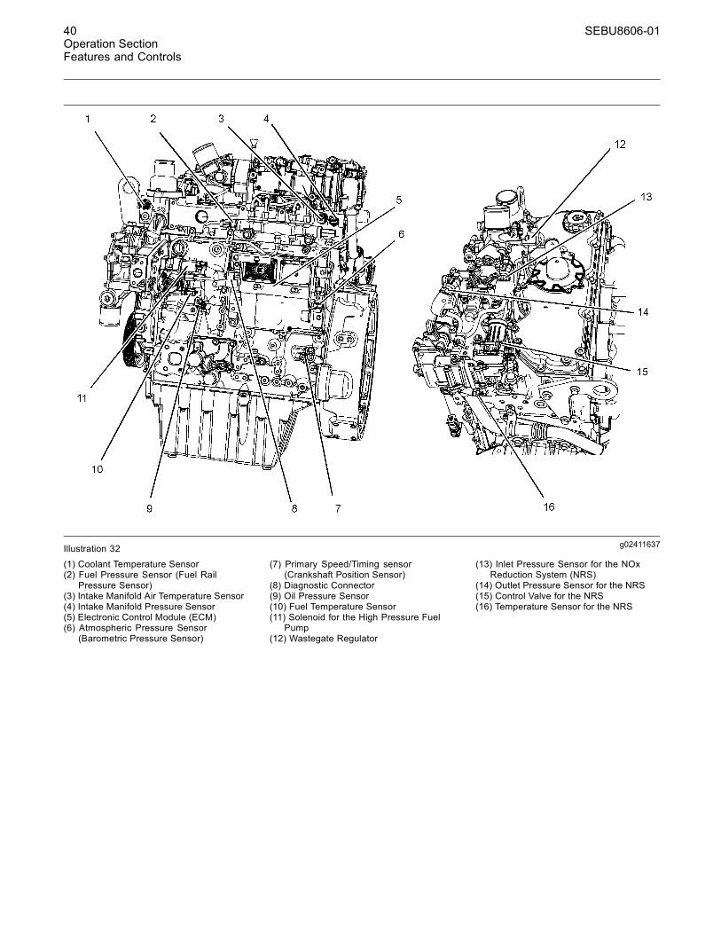
g02411637Illustration 32
(1) Coolant Temperature Sensor(2) Fuel Pressure Sensor (Fuel Rail
Pressure Sensor)(3) Intake Manifold Air Temperature Sensor(4) Intake Manifold Pressure Sensor(5) Electronic Control Module (ECM)(6) Atmospheric Pressure Sensor
(Barometric Pressure Sensor)
(7) Primary Speed/Timing sensor(Crankshaft Position Sensor)
(8) Diagnostic Connector(9) Oil Pressure Sensor(10) Fuel Temperature Sensor(11) Solenoid for the High Pressure Fuel
Pump(12) Wastegate Regulator
(13) Inlet Pressure Sensor for the NOxReduction System (NRS)
(14) Outlet Pressure Sensor for the NRS(15) Control Valve for the NRS(16) Temperature Sensor for the NRS

SEBU8606-01 41Operation Section
Features and Controls
g02411837Illustration 33(17) Back Pressure Valve(18) Alternator
(19) Secondary Speed/Timing Sensor(Camshaft Position Sensor)
(20) Starting Motor
(21) Water in Fuel Switch(22) Oil Level Switch (if Equipped)(23) Electric Priming Pump
g02413838Illustration 34
(1) Coolant Temperature Sensor(2) Fuel Pressure Sensor (Fuel Rail
Pressure Sensor)
(3) Intake Manifold Air Temperature Sensor(4) Intake Manifold Pressure Sensor(5) Electronic Control Module (ECM)

42 SEBU8606-01Operation SectionFeatures and Controls
g02413839Illustration 35(6) Atmospheric Pressure Sensor
(Barometric Pressure Sensor)(7) Primary Speed/Timing sensor
(Crankshaft Position Sensor)(8) Diagnostic Connector(9) Oil Pressure Sensor
g02413840Illustration 36
(10) Fuel Temperature Sensor(11) Solenoid for the High Pressure Fuel
Pump
(12) Wastegate Regulator(13) Inlet Pressure Sensor for the NOx
Reduction System (NRS)
(14) Outlet Pressure Sensor for the NRS
SEBU8606-01 43Operation Section
Features and Controls
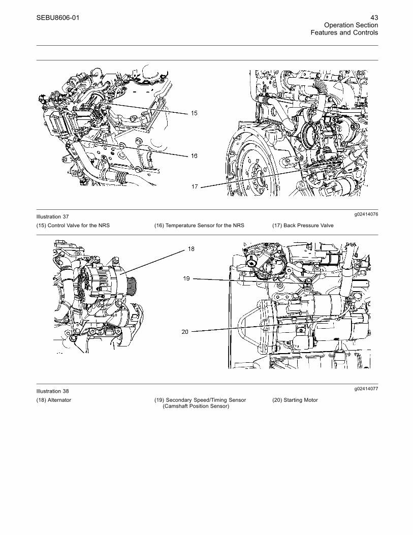
g02414076Illustration 37(15) Control Valve for the NRS (16) Temperature Sensor for the NRS (17) Back Pressure Valve
g02414077Illustration 38
(18) Alternator (19) Secondary Speed/Timing Sensor(Camshaft Position Sensor)
(20) Starting Motor
44 SEBU8606-01Operation SectionFeatures and Controls
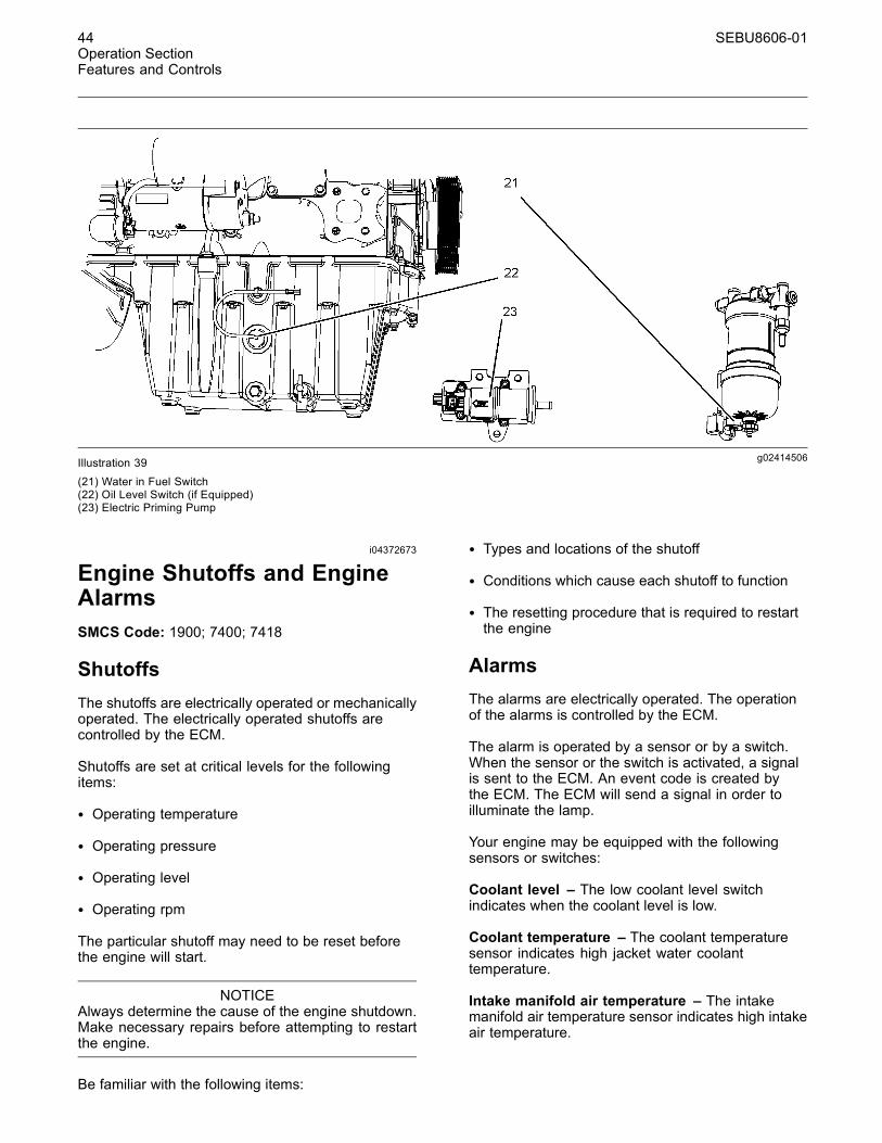
g02414506Illustration 39(21) Water in Fuel Switch(22) Oil Level Switch (if Equipped)(23) Electric Priming Pump
i04372673
Engine Shutoffs and EngineAlarmsSMCS Code: 1900; 7400; 7418
ShutoffsThe shutoffs are electrically operated or mechanicallyoperated. The electrically operated shutoffs arecontrolled by the ECM.
Shutoffs are set at critical levels for the followingitems:
• Operating temperature
• Operating pressure
• Operating level
• Operating rpm
The particular shutoff may need to be reset beforethe engine will start.
NOTICEAlways determine the cause of the engine shutdown.Make necessary repairs before attempting to restartthe engine.
Be familiar with the following items:
• Types and locations of the shutoff
• Conditions which cause each shutoff to function
• The resetting procedure that is required to restartthe engine
AlarmsThe alarms are electrically operated. The operationof the alarms is controlled by the ECM.
The alarm is operated by a sensor or by a switch.When the sensor or the switch is activated, a signalis sent to the ECM. An event code is created bythe ECM. The ECM will send a signal in order toilluminate the lamp.
Your engine may be equipped with the followingsensors or switches:
Coolant level – The low coolant level switchindicates when the coolant level is low.
Coolant temperature – The coolant temperaturesensor indicates high jacket water coolanttemperature.
Intake manifold air temperature – The intakemanifold air temperature sensor indicates high intakeair temperature.
SEBU8606-01 45Operation Section
Features and Controls
Intake manifold pressure – The intake manifoldpressure sensor checks the rated pressure in theengine manifold.
Fuel rail pressure – The fuel rail pressure sensorchecks for high pressure or low pressure in the fuelrail.
Engine oil pressure – The engine oil pressuresensor indicates when oil pressure drops below ratedsystem pressure, at a set engine speed.
Engine overspeed – If the engine rpm exceeds theoverspeed setting, the alarm will be activated.
Air filter restriction – The switch checks the airfilter when the engine is operating.
User-Defined switch – This switch can shut downthe engine remotely.
Water in fuel switch – This switch checks for waterin the primary fuel filter when the engine is operating.
Fuel temperature – The fuel temperature sensormonitors the pressurized fuel in the high-pressurefuel pump.
Note: The sensing element of the coolanttemperature switch must be submerged in coolantin order to operate.
Engines may be equipped with alarms in orderto alert the operator when undesirable operatingconditions occur.
NOTICEWhen an alarm is activated, corrective measuresmustbe taken before the situation becomes an emergencyin order to avoid possible engine damage.
If corrective measures are not taken within areasonable time, engine damage could result. Thealarm will continue until the condition is corrected.The alarm may need to be reset.
TestingTurning the keyswitch to the ON position will checkthe indicator lights on the control panel. All theindicator lights will be illuminated for 2 seconds afterthe keyswitch is operated. Replace suspect bulbsimmediately.
Refer to Troubleshooting, KENR9111 for moreinformation.
i03554501
OverspeedSMCS Code: 1900; 1907; 1912; 7427
• ECM ______________________Electronic Control Module
• RPM ________________________ Revolutions Per Minute
An overspeed is detected by the speed/timingsensors.
The default setting for an overspeed is 3000 rpm.The ECM will cut the power to the electronic unitinjectors, until the rpm drops below 200 rpm of theoverspeed setting. A diagnostic fault code will belogged into the ECM memory and a warning lamp willindicate a diagnostic fault code.
An overspeed can be set from 2600 rpm to 3000 rpm.This setting depends on the application.
46 SEBU8606-01Operation SectionEngine Diagnostics
Engine Diagnosticsi01796959
Self-DiagnosticsSMCS Code: 1000; 1900; 1901; 1902
Caterpillar Electronic Engines have the capability toperform a self-diagnostics test. When the systemdetects an active problem, a diagnostic lampis activated. Diagnostic codes will be stored inpermanent memory in the Electronic Control Module(ECM). The diagnostic codes can be retrieved byusing Caterpillar electronic service tools.
Some installations have electronic displays thatprovide direct readouts of the engine diagnosticcodes. Refer to the manual that is provided by theOEM for more information on retrieving enginediagnostic codes.
Active codes represent problems that currently exist.These problems should be investigated first.
Logged codes represent the following items:
• Intermittent problems
• Recorded events
• Performance history
The problems may have been repaired since thelogging of the code. These codes do not indicate thata repair is needed. The codes are guides or signalswhen a situation exists. Codes may be helpful totroubleshoot problems.
When the problems have been corrected, thecorresponding logged fault codes should be cleared.
i03554520
Diagnostic LampSMCS Code: 1000; 1900; 1901; 1902; 7451
A diagnostic lamp is used to indicate the existenceof an active fault. A fault diagnostic code will remainactive until the problem is repaired. The diagnosticcode may be retrieved by using the electronic servicetool.
i04215570
Diagnostic Flash CodeRetrievalSMCS Code: 1000; 1900; 1901; 1902
Use the “DIAGNOSTIC” lamp or an electronic servicetool to determine the diagnostic flash code.
Use the following procedure to retrieve the flashcodes if the engine is equipped with a “DIAGNOSTIC”lamp:
1. Move the keyswitch from the on/off two timeswithin 3 seconds.
A flashing YELLOW lamp indicates a 3-digit code forthe engine. The sequence of flashes represents thesystem diagnostic message. Count the first sequenceof flashes in order to determine the first digit of theflash code. After a two second pause, the secondsequence of flashes will identify the second digit ofthe flash code. After the second pause, the thirdsequence of flashes will identify the flash code.
Table 3
Flash Code Table
Description Flash Code
Injector fault 111
Injector number 2 current out of range 112
Injector number 3 current out of range 113
Injector number 4 current out of range 114
Injector number 5 current out of range(6 cylinder only)
115
Injector number 6 current out of range(6 cylinder only)
116
Intake manifold air temperaturesensor out of range
133
Engine speed sensor out of range 141
Engine timing offset fault 143
Engine operation mode selectorswitch erratic, intermittent, orincorrect
144
High air filter restriction - Warning 151
Atmospheric pressure sensor out ofrange
152
Throttle position sensor out of range 154
Secondary throttle position sensorout of range
155
Oil pressure sensor out of range 157
(continued)

SEBU8606-01 47Operation SectionEngine Diagnostics
(Table 3, contd)
Fuel rail pressure sensor out of range 159
Fuel temperature sensor out of range 165
Engine coolant temperature sensorout of range
168
Low Engine Coolant Level -Shutdown
169
Turbo wastegate drive out of range 177
Intake manifold pressure sensor outof range
197
Glow plug start aid relay currentabove normal
199
Diesel Particulate Filter DPF Intaketemperature sensor out of range
224
DPF Soot sensors out of range 226
Exhaust gas recirculationtemperature/pressure out of range
227
Exhaust gas recirculation valvecontrol current out of range
228
Exhaust gas recirculation valvecontrol voltage out of range
229
Exhaust gas recirculation pressuresensor out of range
231
Air inlet temperature sensor voltageout of range
232
Ether injection control solenoid out ofrange
233
Idle validation switch #1 erratic,intermittent, or incorrect
245
Idle validation switch #2 erratic,intermittent, or incorrect
246
Exhaust Gas Recirculation OutletPressure Sensor out of range
247
Exhaust back pressure regulatorposition voltage out of range
249
Engine Fuel Supply Lift Pump Relayout of range
253
Personality module erratic,intermittent, or incorrect
415
Machine security system moduleabnormal update rate
426
Ignition key switch loss of signal 429
Electrical System Voltage fault 511
SAE J1939 Data Link abnormalupdate rate
514
5 Volt sensor DC power supplyvoltage out of range
516
(continued)
(Table 3, contd)
8 V DC Supply voltage out of range 517
Programmed parameter fault erratic,intermittent, or incorrect
527
5 Volt Sensor DC Power Supply #2out of range
528
No diagnostic code detected 551
Refer to Troubleshooting, “Diagnostic Flash CodeCross Reference” for more information.
i03554529
Fault LoggingSMCS Code: 1000; 1900; 1901; 1902
The system provides the capability of Fault Logging.When the Electronic Control Module (ECM)generates an active diagnostic code, the code will belogged in the memory of the ECM. The codes thathave been logged in the memory of the ECM canbe retrieved with electronic service tools. The codesthat have been logged can be cleared with electronicservice tools. The codes that have been logged in thememory of the ECM will be automatically cleared fromthe memory after 100 hours. The following faults cannot be cleared from the memory of the ECM withoutusing a factory password: overspeed, low engine oilpressure, and high engine coolant temperature.

48 SEBU8606-01Operation SectionEngine Diagnostics
i03554534
Engine Operation with ActiveDiagnostic CodesSMCS Code: 1000; 1900; 1901; 1902
If a diagnostic lamp illuminates during normal engineoperation, the system has identified a situation thatis not within the specification. Use electronic servicetools to check the active diagnostic codes.
Note: If the customer has selected “DERATE” and ifthere is a low oil pressure condition, the ElectronicControl Module (ECM) will limit the engine poweruntil the problem is corrected. If the oil pressure iswithin the normal range, the engine may be operatedat the rated speed and load. However, maintenanceshould be performed as soon as possible.
The active diagnostic code should be investigated.The cause of the problem should be corrected assoon as possible. If the cause of the active diagnosticcode is repaired and there is only one activediagnostic code, the diagnostic lamp will turn off.
Operation of the engine and performance of theengine can be limited as a result of the activediagnostic code that is generated. Accelerationrates may be significantly slower. Refer to theTroubleshooting Guide for more information on therelationship between these active diagnostic codesand engine performance.
i01797063
Engine Operation withIntermittent Diagnostic CodesSMCS Code: 1000; 1900; 1901; 1902
If a diagnostic lamp illuminates during normal engineoperation and the diagnostic lamp shuts off, anintermittent fault may have occurred. If a fault hasoccurred, the fault will be logged into the memory ofthe Electronic Control Module (ECM).
In most cases, it is not necessary to stop the enginebecause of an intermittent code. However, theoperator should retrieve the logged fault codesand the operator should reference the appropriateinformation in order to identify the nature of the event.The operator should log any observation that couldhave caused the lamp to light.
• Low power
• Limits of the engine speed
• Excessive smoke, etc
This information can be useful to help troubleshootthe situation. The information can also be used forfuture reference. For more information on diagnosticcodes, refer to the Troubleshooting Guide for thisengine.
i04217251
Configuration ParametersSMCS Code: 1000; 1900; 1901; 1902
The engine electronic control module (ECM) hastwo types of configuration parameters. The systemconfiguration parameters and the customer specifiedparameters.
The electronic service tool is required in order to alterthe configuration parameters.
System Configuration ParametersSystem configuration parameters affect the emissionsof the engine or the power of the engine. Systemconfiguration parameters are programmed at thefactory. Normally, system configuration parameterswould never require changing through the lifeof the engine. System configuration parametersmust be reprogrammed if an ECM is replaced.System configuration parameters do not requirereprogrammed if the ECM software is changed.Factory passwords are required to change theseparameters.
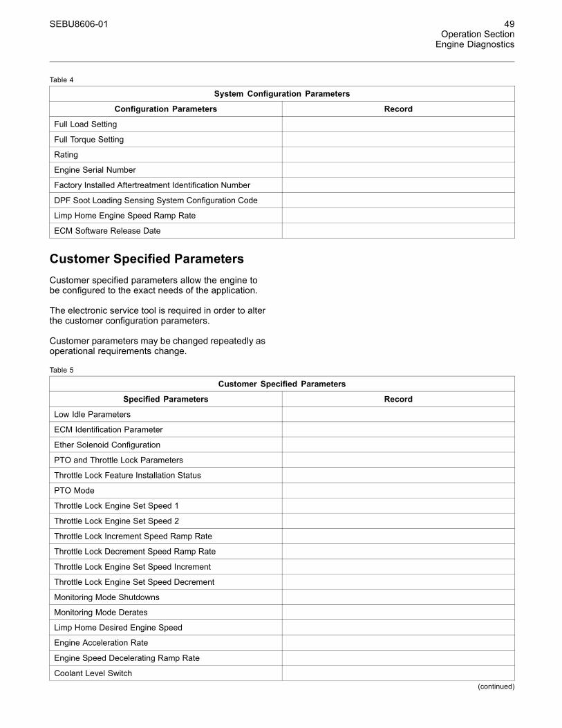
SEBU8606-01 49Operation SectionEngine Diagnostics
Table 4
System Configuration Parameters
Configuration Parameters Record
Full Load Setting
Full Torque Setting
Rating
Engine Serial Number
Factory Installed Aftertreatment Identification Number
DPF Soot Loading Sensing System Configuration Code
Limp Home Engine Speed Ramp Rate
ECM Software Release Date
Customer Specified ParametersCustomer specified parameters allow the engine tobe configured to the exact needs of the application.
The electronic service tool is required in order to alterthe customer configuration parameters.
Customer parameters may be changed repeatedly asoperational requirements change.
Table 5
Customer Specified Parameters
Specified Parameters Record
Low Idle Parameters
ECM Identification Parameter
Ether Solenoid Configuration
PTO and Throttle Lock Parameters
Throttle Lock Feature Installation Status
PTO Mode
Throttle Lock Engine Set Speed 1
Throttle Lock Engine Set Speed 2
Throttle Lock Increment Speed Ramp Rate
Throttle Lock Decrement Speed Ramp Rate
Throttle Lock Engine Set Speed Increment
Throttle Lock Engine Set Speed Decrement
Monitoring Mode Shutdowns
Monitoring Mode Derates
Limp Home Desired Engine Speed
Engine Acceleration Rate
Engine Speed Decelerating Ramp Rate
Coolant Level Switch(continued)
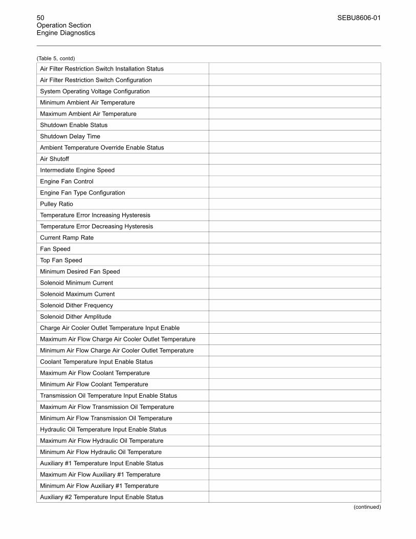
50 SEBU8606-01Operation SectionEngine Diagnostics
(Table 5, contd)
Air Filter Restriction Switch Installation Status
Air Filter Restriction Switch Configuration
System Operating Voltage Configuration
Minimum Ambient Air Temperature
Maximum Ambient Air Temperature
Shutdown Enable Status
Shutdown Delay Time
Ambient Temperature Override Enable Status
Air Shutoff
Intermediate Engine Speed
Engine Fan Control
Engine Fan Type Configuration
Pulley Ratio
Temperature Error Increasing Hysteresis
Temperature Error Decreasing Hysteresis
Current Ramp Rate
Fan Speed
Top Fan Speed
Minimum Desired Fan Speed
Solenoid Minimum Current
Solenoid Maximum Current
Solenoid Dither Frequency
Solenoid Dither Amplitude
Charge Air Cooler Outlet Temperature Input Enable
Maximum Air Flow Charge Air Cooler Outlet Temperature
Minimum Air Flow Charge Air Cooler Outlet Temperature
Coolant Temperature Input Enable Status
Maximum Air Flow Coolant Temperature
Minimum Air Flow Coolant Temperature
Transmission Oil Temperature Input Enable Status
Maximum Air Flow Transmission Oil Temperature
Minimum Air Flow Transmission Oil Temperature
Hydraulic Oil Temperature Input Enable Status
Maximum Air Flow Hydraulic Oil Temperature
Minimum Air Flow Hydraulic Oil Temperature
Auxiliary #1 Temperature Input Enable Status
Maximum Air Flow Auxiliary #1 Temperature
Minimum Air Flow Auxiliary #1 Temperature
Auxiliary #2 Temperature Input Enable Status(continued)
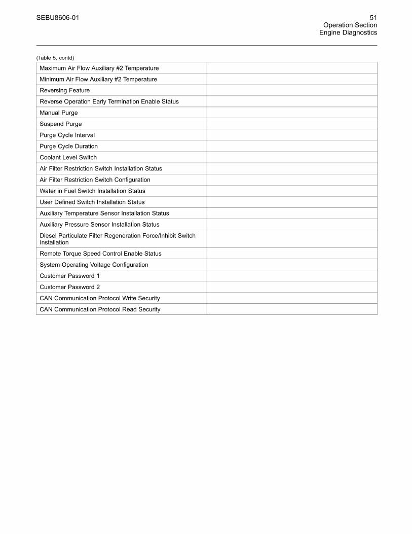
SEBU8606-01 51Operation SectionEngine Diagnostics
(Table 5, contd)
Maximum Air Flow Auxiliary #2 Temperature
Minimum Air Flow Auxiliary #2 Temperature
Reversing Feature
Reverse Operation Early Termination Enable Status
Manual Purge
Suspend Purge
Purge Cycle Interval
Purge Cycle Duration
Coolant Level Switch
Air Filter Restriction Switch Installation Status
Air Filter Restriction Switch Configuration
Water in Fuel Switch Installation Status
User Defined Switch Installation Status
Auxiliary Temperature Sensor Installation Status
Auxiliary Pressure Sensor Installation Status
Diesel Particulate Filter Regeneration Force/Inhibit SwitchInstallation
Remote Torque Speed Control Enable Status
System Operating Voltage Configuration
Customer Password 1
Customer Password 2
CAN Communication Protocol Write Security
CAN Communication Protocol Read Security

52 SEBU8606-01Operation SectionEngine Starting
Engine Startingi03648917
Before Starting EngineSMCS Code: 1000; 1400; 1450
Perform the required daily maintenance and otherperiodic maintenance before the engine is started.Inspect the engine compartment. This inspection canhelp prevent major repairs at a later date. Refer to theOperation and Maintenance Manual, “MaintenanceInterval Schedule” for more information.
• Ensure that the engine has an adequate fuelsupply.
• Open the fuel supply valve (if equipped).
NOTICEAll valves in the fuel return line must be open and fuelsupply lines must be open. Damage to the fuel systemcan occure if fuel lines are closed with the engine inoperation.
If the engine has not been started for several weeks,fuel may have drained from the fuel system. Airmay have entered the filter housing. Also, when fuelfilters have been changed, some air pockets will betrapped in the engine. In these instances, prime thefuel system. Refer to the Operation and MaintenanceManual, “Fuel System - Prime” for more informationon priming the fuel system. Also, check that the fuelspecification is correct and that the fuel conditionis correct. Refer to the Operation and MaintenanceManual, “Fuel Recommendations”.
Engine exhaust contains products of combustionwhich may be harmful to your health. Always startand operate the engine in a well ventilated areaand, if in an enclosed area, vent the exhaust to theoutside.
• Do not start the engine or move any of the controlsif there is a “DO NOT OPERATE” warning tag orsimilar warning tag attached to the start switch orto the controls.
• Reset all of the shutoffs or alarm components.
• Ensure that any driven equipment has beendisengaged. Minimize electrical loads or removeany electrical loads.
i02322203
Starting the EngineSMCS Code: 1000; 1450
Note: Do not adjust the engine speed control duringstart-up. The electronic control module (ECM) willcontrol the engine speed during start-up.
Starting the Engine1. Disengage any equipment that is driven by theengine.
2. Turn the keyswitch to the RUN position. Leave thekeyswitch in the RUN position until the warninglight for the glow plugs is extinguished.
3. When the warning light for the glow plugs isextinguished turn the keyswitch to the STARTposition in order to engage the electric startingmotor and crank the engine.
Note: The operating period of the warning light forthe glow plugs will change due to the temperatureof the engine.
NOTICEDo not engage the starting motor when flywheel isturning. Do not start the engine under load.
If the engine fails to start within 30 seconds, releasethe starter switch or button and wait two minutes toallow the starting motor to cool before attempting tostart the engine again.
4. Allow the keyswitch to return to the RUN positionafter the engine starts.
5. Repeat step 2 through step 4 if the engine failsto start.
i03586430
Cold Weather StartingSMCS Code: 1000; 1250; 1450; 1453; 1456; 1900
Do not use aerosol types of starting aids such asether. Such use could result in an explosion andpersonal injury.
Startability will be improved at temperatures below−18 °C (0 °F) from the use of a jacket water heateror extra battery capacity.
SEBU8606-01 53Operation SectionEngine Starting
When Group 2 diesel fuel is used, the following itemsprovide a means of minimizing starting problemsand fuel problems in cold weather: Engine oil panheaters, jacket water heaters, fuel heaters, andfuel line insulation. For more information, refer toCommercial Diesel Engine Fluids Recommendations, SEBU6251.
Use the procedure that follows for cold weatherstarting.
Note: Do not adjust the engine speed control duringstart-up. The electronic control module (ECM) willcontrol the engine speed during start-up.
1. Disengage any driven equipment.
2. Turn the keyswitch to the RUN position. Leave thekeyswitch in the RUN position until the warninglight for the glow plugs is extinguished.
NOTICEDo not engage the starting motor when flywheel isturning. Do not start the engine under load.
If the engine fails to start within 30 seconds, releasethe starter switch or button and wait two minutes toallow the starting motor to cool before attempting tostart the engine again.
3. When the warning light for the glow plugs isextinguished turn the keyswitch to the STARTposition in order to engage the electric startingmotor and crank the engine.
Note: The operating period of the warning light forthe glow plugs will change due to the temperatureof the engine.
4. Allow the keyswitch to return to the RUN positionafter the engine starts.
5. Repeat step 2 through step 4 if the engine failsto start.
Note: The engine should not be “raced” in order tospeed up the warm up process.
6. Allow the engine to idle for three to five minutes, orallow the engine to idle until the water temperatureindicator begins to rise. When idling after theengine has started in cold weather, increase theengine rpm from 1000 to 1200 rpm. This willwarm up the engine more quickly. Maintainingan elevated low idle speed for extended periodswill be easier with the installation of a handthrottle. Allow the white smoke to disperse beforeproceeding with normal operation.
7. Operate the engine at low load until all systemsreach operating temperature. Check the gaugesduring the warm-up period.
i03653722
Starting with Jump StartCablesSMCS Code: 1000; 1401; 1402; 1900
Improper jump start cable connections can causean explosion resulting in personal injury.
Prevent sparks near the batteries. Sparks couldcause vapors to explode. Do not allow jump startcable ends to contact each other or the engine.
If the installation is not equipped with a backupbattery system, it may be necessary to start theengine from an external electrical source.
For information on troubleshooting the chargingsystem, refer to Special Instruction, REHS0354,“Charging System Troubleshooting”.
Many batteries which are considered unusable arestill rechargeable. After jump starting, the alternatormay not be able to fully recharge batteries thatare severely discharged. The batteries must becharged to the proper voltage with a battery charger.For information on testing and charging, refer tothe Special Instruction, SEHS7633, “Battery TestProcedure”.
NOTICEUsing a battery source with the same voltage as theelectric starting motor. Use ONLY equal voltage forjump starting. The use of higher voltage will damagethe electrical system.
Do not reverse the battery cables. The alternator canbe damaged. Attach ground cable last and removefirst.
When using an external electrical source to start theengine, turn the generator set control switch to the“OFF” position. Turn all electrical accessories OFF be-fore attaching the jump start cables.
Ensure that the main power switch is in the OFF posi-tion before attaching the jump start cables to the en-gine being started.
1. Turn the start switch on the stalled engine to theOFF position. Turn off all the engine's accessories.

54 SEBU8606-01Operation SectionEngine Starting
2. Connect one positive end of the jump start cableto the positive cable terminal of the dischargedbattery. Connect the other positive end of the jumpstart cable to the positive cable terminal of theelectrical source.
3. Connect one negative end of the jump start cableto the negative cable terminal of the electricalsource. Connect the other negative end of thejump start cable to the engine block or to thechassis ground. This procedure helps to preventpotential sparks from igniting the combustiblegases that are produced by some batteries.
Note: The engine ECM must be powered before thestarting motor is operated or damage can occur.
4. Start the engine in the normal operating procedure.Refer to this Operation and Maintenance Manual,“Starting the Engine”.
5. Immediately after the engine is started, disconnectthe jump start cables in reverse order.
After jump starting, the alternator may not be able tofully recharge batteries that are severely discharged.The batteries must be replaced or charged to theproper voltage with a battery charger after the engineis stopped. Many batteries which are consideredunusable are still rechargeable. Refer to Operationand Maintenance Manual, “Battery - Replace” andTesting and Adjusting Manual, “Battery - Test”.
Refer to the Electrical Schematic for your engine.Consult your Caterpillar dealer for more information.
i02330138
After Starting EngineSMCS Code: 1000
Note: In ambient temperatures from 0 to 60°C(32 to 140°F), the warm-up time is approximatelythree minutes. In temperatures below 0°C (32°F),additional warm-up time may be required.
When the engine idles during warm-up, observe thefollowing conditions:
Do not check the high pressure fuel lines with theengine or the starting motor in operation. If youinspect the engine in operation, always use theproper inspection procedure in order to avoid afluid penetration hazard. Refer to Operation andMaintenance Manual, “General hazard Information”.
• Check for any fluid or for any air leaks at idle rpmand at one-half full rpm (no load on the engine)before operating the engine under load. This is notpossible in some applications.
• Allow the engine to idle for three to five minutes, orallow the engine to idle until the water temperatureindicator begins to rise. Check all gauges duringthe warm-up period.
Note: Gauge readings should be observed andthe data should be recorded frequently while theengine is operating. Comparing the data over timewill help to determine normal readings for eachgauge. Comparing data over time will also helpdetect abnormal operating developments. Significantchanges in the readings should be investigated.

SEBU8606-01 55Operation SectionEngine Operation
Engine Operationi03858430
Engine OperationSMCS Code: 1000
Proper operation and maintenance are key factorsin obtaining the maximum life and economy ofthe engine. If the directions in the Operation andMaintenance Manual are followed, costs can beminimized and engine service life can be maximized.
The time that is needed for the engine to reachnormal operating temperature can be less than thetime taken for a walk-around inspection of the engine.
The engine can be operated at the rated rpm afterthe engine is started and after the engine reachesoperating temperature. The engine will reach normaloperating temperature sooner during a low enginespeed (rpm) and during a low-power demand. Thisprocedure is more effective than idling the engineat no load. The engine should reach operatingtemperature in a few minutes.
Avoid excess idling. Excessive idling causes carbonbuildup, engine slobber, and soot loading of theDiesel Particulate Filter (DPF). These issues areharmful to the engine.
Gauge readings should be observed and the datashould be recorded frequently while the engineis operating. Comparing the data over time willhelp to determine normal readings for each gauge.Comparing data over time will also help detectabnormal operating developments. Significantchanges in the readings should be investigated.
Reduction of Particulate EmissionsThe Diesel Particulate Filter (DPF) will reduceparticulate emissions. The DPF collects the soot andany ash that is produced by the combustion in theengine. During regeneration, the soot is convertedinto a gas which is released into the atmosphere. TheAsh remains in the DPF.
The temperature of the DPF must be above aparticular value in order for regeneration to occur.The exhaust gas provides heat for the regenerationprocess.
Passive Regeneration – The engine providessufficient exhaust gas temperature for regeneration.
Engine Operation and a DPF
During normal engine operation, the operator of theengine may notice the lack of black smoke from theexhaust system.
Passive regeneration is the process that is usedby the DPF in order to remove soot from the DPF.In some applications, the engine idle speed willautomatically be increased in order to allow passiveregeneration to occur.
i01646335
Engaging the DrivenEquipmentSMCS Code: 1000
1. Operate the engine at one-half of the rated rpm,when possible.
2. Engage the driven equipment without a load onthe equipment, when possible.
Interrupted starts put excessive stress on the drivetrain. Interrupted starts also waste fuel. To get thedriven equipment in motion, engage the clutchsmoothly with no load on the equipment. Thismethod should produce a start that is smooth andeasy. The engine rpm should not increase and theclutch should not slip.
3. Ensure that the ranges of the gauges are normalwhen the engine is operating at one-half ofthe rated rpm. Ensure that all gauges operateproperly.
4. Increase the engine rpm to the rated rpm. Alwaysincrease the engine rpm to the rated rpm beforethe load is applied.
5. Apply the load. Begin operating the engine at lowload. Check the gauges and equipment for properoperation. After normal oil pressure is reachedand the temperature gauge begins to move,the engine may be operated at full load. Checkthe gauges and equipment frequently when theengine is operated under load.
Extended operation at low idle or at reduced loadmay cause increased oil consumption and carbonbuildup in the cylinders. This carbon buildupresults in a loss of power and/or poor performance.

56 SEBU8606-01Operation SectionEngine Operation
i04018250
Fuel Conservation PracticesSMCS Code: 1000; 1250
The efficiency of the engine can affect the fueleconomy. Caterpillar's design and technology inmanufacturing provides maximum fuel efficiency inall applications. Follow the recommended proceduresin order to attain optimum performance for the lifeof the engine.
• Avoid spilling fuel.
Fuel expands when the fuel is warmed up. The fuelmay overflow from the fuel tank. Inspect fuel lines forleaks. Repair the fuel lines, as needed.
• Be aware of the properties of the different fuels.Use only the recommended fuels. Refer to theOperations and Maintenance Manual, “FuelRecommendations”for further information.
• Avoid unnecessary idling.
Shut off the engine rather than idle for long periods oftime.
• Observe the service indicator frequently. Keep theair cleaner elements clean.
• Ensure that the turbocharger is operating correctly.For more information refer to this Operation andMaintenance Manual, “Turbocharger - Inspect”.
• Maintain a good electrical system.
One faulty battery cell will overwork the alternator.This fault will consume excess power and excessfuel.
• The belt should be in good condition. Refer to theSystems Operation, Testing and Adjusting, “V -Belt Test” for further information.
• Ensure that all of the connections of the hoses aretight. The connections should not leak.
• Ensure that the driven equipment is in goodworking order.
• Cold engines consume excess fuel. Utilize heatfrom the jacket water system and the exhaustsystem, when possible. Keep cooling systemcomponents clean and keep cooling systemcomponents in good repair. Never operate theengine without water temperature regulators.All of these items will help maintain operatingtemperatures.

SEBU8606-01 57Operation SectionEngine Stopping
Engine Stoppingi02334873
Stopping the EngineSMCS Code: 1000; 7000
NOTICEStopping the engine immediately after it has beenworking under load, can result in overheating and ac-celerated wear of the engine components.
Avoid accelerating the engine prior to shutting it down.
Avoiding hot engine shutdowns will maximize tur-bocharger shaft and bearing life.
Note: Individual applications will have differentcontrol systems. Ensure that the shutoff proceduresare understood. Use the following general guidelinesin order to stop the engine.
1. Remove the load from the engine. Reduce theengine speed (rpm) to low idle. Allow the engineto idle for five minutes in order to cool the engine.
2. Stop the engine after the cool down periodaccording to the shutoff system on the engine andturn the ignition key switch to the OFF position.If necessary, refer to the instructions that areprovided by the OEM.
i03554860
Emergency StoppingSMCS Code: 1000; 7418
NOTICEEmergency shutoff controls are for EMERGENCY useONLY. DO NOT use emergency shutoff devices orcontrols for normal stopping procedure.
Ensure that any components for the external systemthat support the engine operation are secured afterthe engine is stopped.
Emergency Stop Button
g00104303Illustration 40
Typical emergency stop button
The emergency stop button is in the OUT position fornormal engine operation. Push the emergency stopbutton. The engine will not start when the button islocked. Turn the button clockwise in order to reset.
Refer to Operation and Maintenance Manual,“Features and Controls” for the location and theoperation of the emergency stop button.
i03648931
After Stopping EngineSMCS Code: 1000
Note: Before you check the engine oil, do not operatethe engine for at least 10 minutes in order to allowthe engine oil to return to the oil pan.
58 SEBU8606-01Operation SectionEngine Stopping
Contact with high pressure fuel may cause fluidpenetration and burn hazards. High pressure fu-el spray may cause a fire hazard. Failure to fol-low these inspection, maintenance and service in-structions may cause personal injury or death.
• After the engine has stopped, you must wait for10 minutes in order to allow the fuel pressure tobe purged from the high pressure fuel lines beforeany service or repair is performed on the enginefuel lines. If necessary, perform minor adjustments.Repair any leaks from the low pressure fuelsystem and from the cooling, lubrication or airsystems. Replace any high pressure fuel line thathas leaked. Refer to Disassembly and assemblyManual, “Fuel Injection Lines - Install”.
• Check the crankcase oil level. Maintain the oil levelbetween the “MIN” mark and the “MAX” mark onthe engine oil level gauge.
• If the engine is equipped with a service hour meter,note the reading. Perform the maintenance thatis in the Operation and Maintenance Manual,“Maintenance Interval Schedule”.
• Fill the fuel tank in order to help preventaccumulation of moisture in the fuel. Do not overfillthe fuel tank.
NOTICEOnly use antifreeze/coolant mixtures recommended inthe Refill Capacities and Recommendations topic thatis in this Operation and Maintenance Manual. Failureto do so can cause engine damage.
Pressurized System: Hot coolant can cause seri-ous burns. To open the cooling system filler cap,stop the engine and wait until the cooling systemcomponents are cool. Loosen the cooling systempressure cap slowly in order to relieve the pres-sure.
• Allow the engine to cool. Check the coolant level.
• Check the coolant for correct antifreeze protectionand the correct corrosion protection. Add thecorrect coolant/water mixture, if necessary.
• Perform all required periodic maintenance on alldriven equipment. This maintenance is outlined inthe instructions from the OEM.

SEBU8606-01 59Operation Section
Cold Weather Operation
Cold Weather Operationi04224330
Cold Weather OperationSMCS Code: 1000; 1250
Caterpillar Diesel Engines can operate effectively incold weather. During cold weather, the starting andthe operation of the diesel engine is dependent onthe following items:
• The type of fuel that is used
• The viscosity of the engine oil
• The operation of the glow plugs
• Optional Cold starting aid
• Battery condition
Refer to Special Publication, SEBU5898, “ColdWeather Recommendations for CaterpillarMachines”.
This section will cover the following information:
• Potential problems that are caused by cold-weatheroperation
• Suggest steps which can be taken in order tominimize starting problems and operating problemswhen the ambient air temperature is between“0° to −40 °C (32° to -40 °F)”.
The operation and maintenance of an engine infreezing temperatures is complex . This complexity isbecause of the following conditions:
• Weather conditions
• Engine applications
Recommendations from your Caterpillar dealer arebased on past proven practices. The information thatis contained in this section provides guidelines forcold-weather operation.
Hints for Cold Weather Operation• If the engine will start, operate the engine until aminimum operating temperature of 80° C (176° F)is achieved. Achieving operating temperature willhelp prevent the intake valves and exhaust valvesfrom sticking.
• The cooling system and the lubrication systemfor the engine do not lose heat immediately uponshutdown. This means that an engine can be shutdown for a period and the engine can still startreadily.
• Install the correct specification of engine lubricantbefore the beginning of cold weather.
• Check all rubber parts (hoses, fan drive belts)weekly.
• Check all electrical wiring and connections for anyfraying or damaged insulation.
• Keep all batteries fully charged and warm.
• Fill the fuel tank at the end of each shift.
• Drain the water from the fuel system. Refer to thisOperation and Maintenance Manual, “Fuel SystemPrimary Filter/Water Separator - Drain”.
• Check the air cleaners and the air intake daily.Check the air intake more often when you operatein snow.
• Ensure that the glow plugs are in working order.Refer to Troubleshooting , “Glow Plug Starting Aid- Test”.
Personal injury or property damage can resultfrom alcohol or starting fluids.
Alcohol or startingfluids are highly flammable andtoxic and if improperly stored could result in injuryor property damage.
Do not use aerosol types of starting aids such asether. Such use could result in an explosion andpersonal injury.
• For jump starting with cables in cold weather,refer to the Operation and Maintenance Manual,“Starting with Jump Start Cables.” for instructions.
Viscosity of the Engine LubricationOilCorrect engine oil viscosity is essential. Oil viscosityaffects the amount of torque that is needed tocrank the engine. Refer to this Operation andMaintenance Manual, “Fluid Recommendations” forthe recommended viscosity of oil.

60 SEBU8606-01Operation SectionCold Weather Operation
Recommendations for the CoolantProvide cooling system protection for the lowestexpected outside temperature. Refer to this Operationand Maintenance Manual, “Fluid Recommendations”for the recommended coolant mixture.
In cold weather, check the coolant often for thecorrect glycol concentration in order to ensureadequate freeze protection.
Engine Block Heaters
Engine block heaters (if equipped) heat theengine jacket water that surrounds the combustionchambers. This heat provides the following functions:
• Startability is improved.
• Warm up time is reduced.
An electric block heater can be activated once theengine is stopped. A block heater can be 110V dcor 240V dc. The output can be 750/1000W. Consultyour Caterpillar dealer for more information.
Idling the EngineWhen idling after the engine is started in coldweather, increase the engine rpm from 1000 to1200 rpm. This increase in RPM will warm up theengine more quickly. Maintaining an elevated low idlespeed for extended periods will be easier with theinstallation of a hand throttle. The engine should notbe “raced” in order to speed up the warm-up process.
While the engine is idling, the application of a lightload (parasitic load) will assist in achieving theminimum operating temperature. The minimumoperating temperature is 80° C (176° F).
Recommendations for CoolantWarm UpWarm up an engine that has cooled below normaloperating temperatures due to inactivity. Thisprocedure should be performed before the engine isreturned to full operation. During operation in verycold temperature conditions, damage to enginevalve mechanisms can result from engine operationfor short intervals. This damage can happen if theengine is started and the engine is stopped manytimes without being operated in order to warm upcompletely.
When the engine is operated below normal operatingtemperatures, fuel and oil are not completely burnedin the combustion chamber. This fuel and oil causessoft carbon deposits to form on the valve stems.Generally, the deposits do not cause problems andthe deposits are burned off during operation atnormal engine operating temperatures.
When the engine is started and the engine is stoppedmany times without being operated in order to warmup completely, the carbon deposits become thicker.This carbon can cause the following problems:
• Free operation of the valves is prevented.
• Valves become stuck.
• Pushrods may become bent.
• Other damage to valve train components canresult.
For this reason, when the engine is started,the engine must be operated until the coolanttemperature is 80° C (176° F) minimum. Carbondeposits on the valve stems will be kept at a minimumand the free operation of the valves and the valvecomponents will be maintained.
The engine must be thoroughly warmed in order tokeep other engine parts in better condition. Also, theservice life of the engine will be generally extended.Lubrication will be improved. There will be less acidand less sludge in the oil. This improvement willprovide longer service life for the engine bearings,the piston rings, and other parts. However, limitunnecessary idle time to 10 minutes in order toreduce wear and unnecessary fuel consumption.
The Water Temperature Regulator andInsulated Heater Lines
The engine is equipped with a water temperatureregulator. When the engine coolant is below thecorrect operating temperature, jacket water circulatesthrough the engine cylinder block and into theengine cylinder head. The coolant then returns to thecylinder block via an internal passage that bypassesthe valve of the coolant temperature regulator. Thisensures that coolant flows around the engine undercold operating conditions. The water temperatureregulator begins to open when the engine jacketwater has reached the correct minimum operatingtemperature. As the jacket water coolant temperaturerises above the minimum operating temperature thewater temperature regulator opens further allowingmore coolant through the radiator to dissipate excessheat.
SEBU8606-01 61Operation Section
Cold Weather Operation
The progressive opening of the water temperatureregulator operates the progressive closing of thebypass passage between the cylinder block andhead. This process ensures maximum coolant flowto the radiator in order to achieve maximum heatdissipation.
Note: Do not restrict the air flow. Restriction to theair flow can damage the fuel system. Caterpillarstrongly discourages the use of all air flow restrictiondevices such as radiator shutters. Restriction of theair flow can result in the following: high exhausttemperatures, power loss, excessive fan usage, andreduction in fuel economy.
A cab heater is beneficial in very cold weather. Thefeed from the engine and the return lines from thecab should be insulated in order to reduce heat lossto the outside air.
Insulating the Air Inlet and EngineCompartment
When temperatures below −18 °C (−0 °F) will befrequently encountered, an air cleaner inlet thatis located in the engine compartment may bespecified. An air cleaner that is located in the enginecompartment may also minimize the entry of snowinto the air cleaner. Also, heat that is rejected by theengine helps to warm the intake air.
Additional heat can be retained around the engine byinsulating the engine compartment.
Recommendation for Crankcase BreatherProtection
Crankcase ventilation gases contain a large quantityof water vapor. This water vapor can freeze incold ambient conditions and can plug or damagethe crankcase ventilation system. If the engine isoperated in temperatures below −25° C (−13° F),measures must be taken to prevent freezing andplugging of the breather system. Insulated hoses anda heated canister assembly should be installed.
Consult with your Caterpillar dealer for therecommended breather components for operationfrom −25° to -40°C (−13° to -40.°F).
i01457051
Radiator RestrictionsSMCS Code: 1353; 1396
Caterpillar discourages the use of airflow restrictiondevices that are mounted in front of radiators. Airflowrestriction can cause the following conditions:
• High exhaust temperatures
• Power loss
• Excessive fan usage
• Reduction in fuel economy
If an airflow restriction device must be used, thedevice should have a permanent opening directlyin line with the fan hub. The device must have aminimum opening dimension of at least 770 cm2
(120 in2).
A centered opening that is directly in line with the fanhub is specified in order to prevent an interruptedairflow on the fan blades. Interrupted airflow on thefan blades could cause a fan failure.
Caterpillar recommends a warning device for theinlet manifold temperature and/or the installation ofan inlet air temperature gauge. The warning devicefor the inlet manifold temperature should be set at75 °C (167 °F). The inlet manifold air temperatureshould not exceed 75 °C (167 °F). Temperatures thatexceed this limit can cause power loss and potentialengine damage.
i02237624
Fuel and the Effect from ColdWeatherSMCS Code: 1000; 1250
The following fuels are the grades that are availablefor Caterpillar engines:
• No. 1
• No. 2
• Blend of No. 1 and No. 2
No. 2 diesel fuel is the most commonly used fuel.Either No. 1 diesel fuel or a blend of No. 1 and No. 2is best suited for cold weather operation.
62 SEBU8606-01Operation SectionCold Weather Operation
Quantities of No. 1 diesel fuel are limited. No. 1 dieselfuels are usually available during the months of thewinter in the colder climates. During cold weatheroperation, if No. 1 diesel fuel is not available, use No.2 diesel fuel, if necessary.
There are three major differences between No. 1 andNo. 2 diesel fuel. No. 1 diesel fuel has the followingproperties:
• Lower cloud point
• Lower pour point
• Lower rating of kJ (BTU) per unit volume of fuel
When No. 1 diesel fuel is used, a decrease in powerand in fuel efficiency may be noticed. Other operatingeffects should not be experienced.
The cloud point is the temperature when a cloud ofwax crystals begins to form in the fuel. These crystalscan cause the fuel filters to plug. The pour point isthe temperature when diesel fuel will thicken. Thediesel fuel becomes more resistant to flow throughfuel pumps and through fuel lines.
Be aware of these values when diesel fuel ispurchased. Anticipate the average ambienttemperature of the area. Engines that are fueled inone climate may not operate well if the engines aremoved to another climate. Problems can result dueto changes in temperature.
Before troubleshooting for low power or for poorperformance in the winter, check the type of fuel thatis being used.
When No. 2 diesel fuel is used the followingcomponents provide a means of minimizing problemsin cold weather:
• Starting aids
• Engine oil pan heaters
• Engine coolant heaters
• Fuel heaters
• Fuel line insulation
For more information on cold weather operation,see Special Publication, SEBU5898, “Cold WeatherRecommendations”.
i04004437
Fuel Related Components inCold WeatherSMCS Code: 1000; 1250
Fuel TanksCondensation can form in partially filled fuel tanks.Top off the fuel tanks after you operate the engine.
Fuel tanks should contain some provision for drainingwater and sediment from the bottom of the tanks.Some fuel tanks use supply pipes that allow waterand sediment to settle below the end of the fuelsupply pipe.
Some fuel tanks use supply lines that take fueldirectly from the bottom of the tank. If the engine isequipped with this system, regular maintenance ofthe fuel system filter is important.
Drain the water and sediment from any fuel storagetank at the following intervals: weekly, serviceintervals, and refueling of the fuel tank. Thisprocedure will help prevent water and/or sedimentfrom being pumped from the fuel storage tank andinto the engine fuel tank.
Fuel FiltersAfter you change the fuel filter, always prime the fuelsystem in order to remove air bubbles from the fuelsystem. Refer to the Operation and MaintenanceManual in the Maintenance Section for moreinformation on priming the fuel system.
The micron rating and the location of a primary fuelfilter is important in cold-weather operation. Theprimary fuel filter and the fuel supply line are the mostcommon components that are affected by cold fuel.
NOTICEIn order to maximize fuel system life and preventpremature wear out from abrasive particles in thefuel, a four micron[c] absolute high efficiency fuel filteris required for all Caterpillar Electronic Unit Injectors.Caterpillar High Efficiency Fuel Filters meet theserequirements. Consult your Caterpillar dealer for theproper part numbers.
Fuel HeatersFuel heaters help to prevent fuel filters from pluggingin cold weather due to waxing. A fuel heater shouldbe installed in the fuel system before the primaryfuel filter.

SEBU8606-01 63Operation Section
Cold Weather Operation
For further information on fuel heaters, consult yourCaterpillar dealer.
64 SEBU8606-01Maintenance SectionRefill Capacities
Maintenance Section
Refill Capacitiesi04251377
Refill Capacities andRecommendationsSMCS Code: 1348; 1395; 7560
Engine Oil
NOTICEThese recommendations are subject to change with-out notice. Contact your local Caterpillar dealer for themost up-to-date fluids recommendations.
• EMA____________Engine Manufacturers Association
• API_____________________American Petroleum Institute
• SAE___________________________________________Society OfAutomotive Engineers Inc.
• DEO-ULS _______________________________________ DieselEngine Oil-Ultra Low Sulfur
Cat DEO-ULS
Cat DEO-ULS is developed and tested in orderto provide superior protection and life for yourCaterpillar industrial engines.
• Better Detergents
• Advanced Additive Package
• Enhanced Dispersants
• Improved Protection from Thermal breakdown andOxidation Breakdown
Due to significant variations in the quality and inthe performance of commercially available oils,Caterpillar makes the following recommendations:
• Cat DEO-ULS (SAE 10W-30)
• Cat DEO-ULS (SAE 15W-40)
Cat DEO Multigrade oil is available in variousviscosity grades that include SAE 10W-30 and SAE15W-40. To choose the correct viscosity grade for theambient temperature, see illustration 41. Multigradeoils provide the correct viscosity for a broad rangeof operating temperatures. Multigrade oils are alsoeffective in maintaining low oil consumption and lowlevels of piston deposits.
Consult your Caterpillar dealer for part numbers andfor available sizes of containers.
Note: Cat DEO in SAE 15W-40 passes the followingproprietary tests: sticking of the piston ring, oilcontrol tests, wear tests, and soot tests. Proprietarytests help ensure that Caterpillar multigrade oilprovides superior performance in Caterpillar DieselEngines. In addition, Cat DEO Multigrade oil exceedsmany of the performance requirements of othermanufacturers of diesel engines. Therefore, this oil isan excellent choice for many mixed fleets. True highperformance oil is produced with a combinationof the following factors: industry standard tests,proprietary tests, field tests, and prior experiencewith similar formulations. The design and thedevelopment of Caterpillar lubricants that areboth high performance and high quality arebased on these factors.
Commercial Oils
Note: Non-Caterpillar commercial oils are secondchoice oils.
NOTICECaterpillar Strongly Recommend the use of the follow-ing specification of engine oil. Failure to use the appro-priate specification of engine oil will reduce the life ofyour engine. The life of the aftertreatment system willalso be reduced.
Table 6
API Classifications for the Industrial Engine
Oil Specification
ECF-3API CJ-4AECA E9
NOTICEFailure to follow these oil recommendations can causeshortened engine service life due to deposits and/orexcessive wear.
Note: Refer to Special Publication, SEBU6251,“Caterpillar Commercial Diesel Engine FluidsRecommendations” for additional information thatrelates to lubrication for your engine.

SEBU8606-01 65Maintenance Section
Refill Capacities
Lubricant Viscosity Recommendations
The proper SAE viscosity grade of oil is determinedby the minimum ambient temperature duringcold engine start-up, and the maximum ambienttemperature during engine operation.
Refer to illustration 41 (minimum temperature) inorder to determine the required oil viscosity forstarting a cold engine.
Refer to illustration 41 (maximum temperature) inorder to select the oil viscosity for engine operation atthe highest ambient temperature that is anticipated.
Note: Generally, use the highest oil viscosity that isavailable to meet the requirement for the temperatureat start-up.
If ambient temperature conditions at engine start-uprequire the use of multigrade SAE 0W oil, SAE0W-40 viscosity grade is preferred over SAE 0W-20or SAE 0W-30.
g01918619Illustration 41
Supplemental heat is recommended for cold soaked starts belowthe minimum ambient temperature. Supplemental heat may berequired for cold soaked starts that are above the minimumtemperature that is stated, depending on the parasitic load andother factors. Cold soaked starts occur when the engine has notbeen operated for a period. This action will allow the oil to becomemore viscous due to cooler ambient temperatures.
S·O·S Oil Analysis
Caterpillar has developed a tool for maintenancemanagement that evaluates oil degradation and thetool also detects the early signs of wear on internalcomponents. The Caterpillar tool for oil analysis iscalled S·O·S Oil Analysis and the tool is part of theS·O·S Services program. S·O·S Oil Analysis dividesoil analysis into three categories:
• Wear Analysis
• Oil condition
• Additional tests
The wear analysis monitors metal particles, some oiladditives, and some contaminants.
Oil condition uses infrared (IR) analysis to evaluatethe chemistry of the oil. Infrared analysis is also usedto detect certain types of contamination.
Additional tests are used to measure contaminationlevels from water, fuel, or coolant. Oil viscosity andcorrosion protection can be evaluated, as needed.
Refer to Special Publication, SEBU6251, “CaterpillarCommercial Diesel Engine Fluids Recommendations”or contact your local Caterpillar dealer for additionalinformation concerning the S·O·S Oil Analysisprogram.
Lubrication System
The refill capacities for the engine crankcase reflectthe approximate capacity of the crankcase or sumpplus standard oil filters. Auxiliary oil filter systems willrequire additional oil. Refer to the OEM specificationsin order to find the capacity of the auxiliary oil filter.
Table 7
EngineRefill Capacities
Compartmentor System
Minimum (1) Maximum (2)
Crankcase OilSump
6 L (1.6 US gal) 14 L (3.7 US gal)
(1) The minimum value is the approximate capacity for thecrankcase oil sump (aluminum) which includes the standardfactory installed oil filters. Engines with auxiliary oil filters willrequire additional oil. Refer to the OEM specifications for thecapacity of the auxiliary oil filter. The design of the oil pan canchange the oil capacity of the oil pan.
(2) Approximate capacity of the largest crankcase oil sump. Referto OEM for more information.
These values are the approximate capacities forthe crankcase oil sump (aluminum) which includesthe standard factory installed oil filters. Engineswith auxiliary oil filters will require additional oil.Refer to the OEM specifications for the capacity ofthe auxiliary oil filter. The design of the oil pan canchange the oil capacity of the oil pan.

66 SEBU8606-01Maintenance SectionRefill Capacities
Lubricating GreaseCaterpillar provides a range of moderate greasesto extremely high performance greases in order toservice the entire line of Caterpillar products thatoperate throughout the wide variety of climates. Youwill always be able to find a grease that will meetyour machines requirements for a certain application.Caterpillar grease products often exceed Caterpillarspecifications.
Before selecting a grease products for anyapplication, the performance requirements must bedetermined. Consult the grease recommendationsthat are made by the OEM for the equipment whenthe equipment is operated in the expected conditions.Then, consult with your Caterpillar dealer for a list ofgreases and the following related characteristics.
• Performance specifications
• Available sizes of containers
• Part numbers
Always choose a grease that meets therecommendations that are specified by theequipment manufacturer for the application, orchoose a grease that exceeds the recommendationsthat are specified by the equipment manufacturer forthe application.
If it is necessary to choose a single grease for useon all of the equipment at one site, always choosea grease that meets the requirements of the mostdemanding application. A product that barely meetsthe minimum performance requirements will shortenthe life of the part. Use the grease that yields the leasttotal operating cost. Base this cost on an analysisthat includes the costs of the parts, the labor, thedowntime, and the cost of the grease that is used.
Some greases are not chemically compatible.Consult your supplier in order to determine if two ormore greases are compatible.
Purge the grease from a joint at the following times:
• Switching from one grease to another grease
• Switching from one supplier to another supplier
Note: All Caterpillar brand name greases arecompatible with each other.
Note: Refer to Special Publication, SEBU6251,“Caterpillar Commercial Diesel Engine FluidsRecommendations” for additional information thatrelates to lubrication for your engine.
FuelRefer to Special Publication, SEBU6251, “CaterpillarCommercial Diesel Engine Fluids Recommendations”for the Caterpillar Specification for distillate fuel andfor additional information that relates to fuel for yourengine.
Ultra low Sulfur Diesel (ULSD)
The Caterpillar industrial diesel engine must useultra low sulfur diesel fuel. This fuel complies withthe emissions regulations that are prescribed bythe Environmental Protection Agency of the UnitedStates.
Engines that are manufactured by Caterpillar arecertified with the fuel that is prescribed by the UnitedStates Environmental Protection Agency. Enginesthat are manufactured by Caterpillar are certifiedwith the fuel that is prescribed by the EuropeanCertification. Caterpillar does not certify dieselengines on any other fuel.
Note: The owner and the operator of the engine hasthe responsibility of using the fuel that is prescribedby the United States Environmental ProtectionAgency and other appropriate regulatory agencies.
Fuel Additives
Many types of fuel additives are available. Caterpillardoes not generally recommend the use of fueladditives.
In special circumstances, Caterpillar recognizes theneed for fuel additives. Fuel additives need to be usedwith caution. The additive may not be compatible withthe fuel. Some additives may precipitate. This actioncauses deposits in the fuel system. The deposits maycause seizure. Some additives may be corrosive andsome additives may be harmful to the elastomersin the fuel system.
Some additives may damage emission controlsystems. Some additives may cause the amount ofsulfur in the fuel to be greater than 15 ppm.
Contact your fuel supplier for those circumstanceswhen fuel additives are required. Your fuel suppliercan recommend the best additives for yourapplication and for the proper level of treatment.
Note: For the best results, your fuel supplier shouldtreat the fuel when additives are necessary.
CoolantThe following two coolants are used in Caterpillardiesel engines:
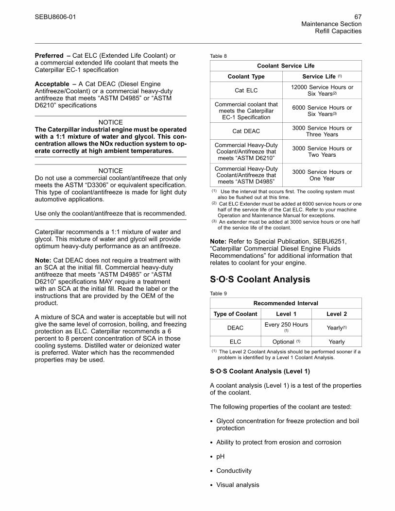
SEBU8606-01 67Maintenance Section
Refill Capacities
Preferred – Cat ELC (Extended Life Coolant) ora commercial extended life coolant that meets theCaterpillar EC-1 specification
Acceptable – A Cat DEAC (Diesel EngineAntifreeze/Coolant) or a commercial heavy-dutyantifreeze that meets “ASTM D4985” or “ASTMD6210” specifications
NOTICEThe Caterpillar industrial enginemust be operatedwith a 1:1 mixture of water and glycol. This con-centration allows the NOx reduction system to op-erate correctly at high ambient temperatures.
NOTICEDo not use a commercial coolant/antifreeze that onlymeets the ASTM “D3306” or equivalent specification.This type of coolant/antifreeze is made for light dutyautomotive applications.
Use only the coolant/antifreeze that is recommended.
Caterpillar recommends a 1:1 mixture of water andglycol. This mixture of water and glycol will provideoptimum heavy-duty performance as an antifreeze.
Note: Cat DEAC does not require a treatment withan SCA at the initial fill. Commercial heavy-dutyantifreeze that meets “ASTM D4985” or “ASTMD6210” specifications MAY require a treatmentwith an SCA at the initial fill. Read the label or theinstructions that are provided by the OEM of theproduct.
A mixture of SCA and water is acceptable but will notgive the same level of corrosion, boiling, and freezingprotection as ELC. Caterpillar recommends a 6percent to 8 percent concentration of SCA in thosecooling systems. Distilled water or deionized wateris preferred. Water which has the recommendedproperties may be used.
Table 8
Coolant Service Life
Coolant Type Service Life (1)
Cat ELC 12000 Service Hours orSix Years(2)
Commercial coolant thatmeets the CaterpillarEC-1 Specification
6000 Service Hours orSix Years(3)
Cat DEAC 3000 Service Hours orThree Years
Commercial Heavy-DutyCoolant/Antifreeze thatmeets “ASTM D6210”
3000 Service Hours orTwo Years
Commercial Heavy-DutyCoolant/Antifreeze thatmeets “ASTM D4985”
3000 Service Hours orOne Year
(1) Use the interval that occurs first. The cooling system mustalso be flushed out at this time.
(2) Cat ELC Extender must be added at 6000 service hours or onehalf of the service life of the Cat ELC. Refer to your machineOperation and Maintenance Manual for exceptions.
(3) An extender must be added at 3000 service hours or one halfof the service life of the coolant.
Note: Refer to Special Publication, SEBU6251,“Caterpillar Commercial Diesel Engine FluidsRecommendations” for additional information thatrelates to coolant for your engine.
S·O·S Coolant AnalysisTable 9
Recommended Interval
Type of Coolant Level 1 Level 2
DEAC Every 250 Hours(1) Yearly(1)
ELC Optional (1) Yearly(1) The Level 2 Coolant Analysis should be performed sooner if aproblem is identified by a Level 1 Coolant Analysis.
S·O·S Coolant Analysis (Level 1)
A coolant analysis (Level 1) is a test of the propertiesof the coolant.
The following properties of the coolant are tested:
• Glycol concentration for freeze protection and boilprotection
• Ability to protect from erosion and corrosion
• pH
• Conductivity
• Visual analysis
68 SEBU8606-01Maintenance SectionRefill Capacities
• Odor analysis
The results are reported, and appropriaterecommendations are made.
Refer to the Maintenance Interval Schedule in thisOperation and Maintenance Manual in order to findthe maintenance interval for collecting the coolantsamples.
S·O·S Coolant Analysis (Level 2)
A coolant analysis (Level 2) is a comprehensivechemical evaluation of the coolant. This analysis isalso a check of the overall condition of the inside ofthe cooling system.
The S·O·S Coolant Analysis has the followingfeatures:
• Full coolant analysis (Level 1)
• Identification of the source of metal corrosion andof contaminants
• Water hardness
• Identification of buildup of the impurities that causecorrosion
• Identification of buildup of the impurities that causescaling
The results are reported, and appropriaterecommendations are made.
Refer to the Maintenance Interval Schedule inthis Operation and Maintenance Manual, “CoolingSystem Coolant Sample (Level 2) - Obtain” forthe maintenance interval for collecting the coolantsamples.
Testing the engine coolant is important to ensure thatthe engine is protected from internal cavitation andfrom corrosion. The analysis also tests the ability ofthe coolant to protect the engine from boiling andfrom freezing. The S·O·S Coolant Analysis can bedone at your Caterpillar dealer. Caterpillar S·O·SCoolant Analysis is the best way to monitor thecondition of your coolant and your cooling system.S·O·S Coolant Analysis is a program that is basedon periodic samples.
Refer to Special Publication, SEBU6251, “CaterpillarCommercial Diesel Engine Fluids Recommendations”for additional information.
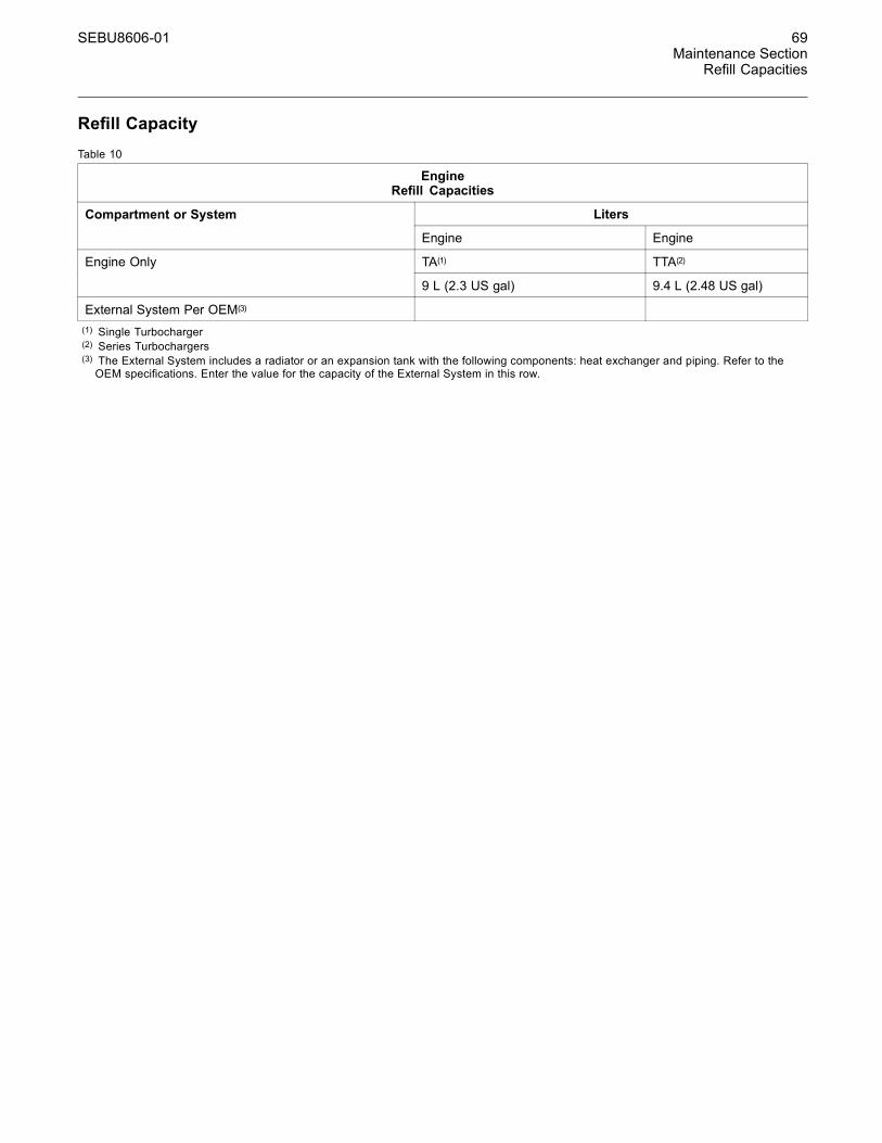
SEBU8606-01 69Maintenance Section
Refill Capacities
Refill CapacityTable 10
EngineRefill Capacities
LitersCompartment or System
Engine Engine
TA(1) TTA(2)Engine Only
9 L (2.3 US gal) 9.4 L (2.48 US gal)
External System Per OEM(3)
(1) Single Turbocharger(2) Series Turbochargers(3) The External System includes a radiator or an expansion tank with the following components: heat exchanger and piping. Refer to theOEM specifications. Enter the value for the capacity of the External System in this row.

70 SEBU8606-01Maintenance SectionMaintenance Recommendations
MaintenanceRecommendations
i03648938
System Pressure ReleaseSMCS Code: 1250; 1300; 1350; 5050
Coolant System
Pressurized system: Hot coolant can cause seri-ous burn. To open cap, stop engine, wait until ra-diator is cool. Then loosen cap slowly to relievethe pressure.
The engine can have the ability to auto start. Ensurethat the power supply is isolated before any serviceor repair is performed.
To relieve the pressure from the coolant system, turnoff the engine. Allow the cooling system pressure capto cool. Remove the cooling system pressure capslowly in order to relieve pressure.
Fuel SystemTo relieve the pressure from the fuel system, turn offthe engine.
High Pressure Fuel Lines
Contact with high pressure fuel may cause fluidpenetration and burn hazards. High pressure fu-el spray may cause a fire hazard. Failure to fol-low these inspection, maintenance and service in-structions may cause personal injury or death.
The high pressure fuel lines are the fuel lines thatare between the high pressure fuel pump and thehigh pressure fuel manifold and the fuel lines that arebetween the fuel manifold and cylinder head. Thesefuel lines are different from fuel lines on other fuelsystems.
This is because of the following differences:
• The high pressure fuel lines are constantly chargedwith high pressure.
• The internal pressures of the high pressure fuellines are higher than other types of fuel system.
Before any service or repair is performed on theengine fuel lines, perform the following tasks:
1. Stop the engine.
2. Wait for 10 minutes.
Do not loosen the high pressure fuel lines in order toremove air from the fuel system.
Engine OilTo relieve pressure from the lubricating system, turnoff the engine.
i04103075
Welding on Engines withElectronic ControlsSMCS Code: 1000
NOTICEBecause the strength of the frame may decrease,some manufacturers do not recommend welding ontoa chassis frame or rail. Consult the OEM of the equip-ment or your Caterpillar dealer regarding welding ona chassis frame or rail.
Proper welding procedures are necessary in orderto avoid damage to the engines ECM, sensors, andassociated components. When possible, removethe component from the unit and then weld thecomponent. If removal of the component is notpossible, the following procedure must be followedwhen you weld on a unit equipped with an ElectronicEngine. The following procedure is considered to bethe safest procedure to weld on a component. Thisprocedure should provide a minimum risk of damageto electronic components.
NOTICEDo not ground the welder to electrical componentssuch as the ECM or sensors. Improper grounding cancause damage to the drive train bearings, hydrauliccomponents, electrical components, and other com-ponents.
Clamp the ground cable from the welder to the com-ponent that will be welded. Place the clamp as closeas possible to the weld. This will help reduce the pos-sibility of damage.
Note: Perform the welding in areas that are free fromexplosive hazards.
1. Stop the engine. Turn the switched power to theOFF position.

SEBU8606-01 71Maintenance Section
Maintenance Recommendations
2. Ensure that the fuel supply to the engine is turnedoff.
3. Disconnect the negative battery cable from thebattery. If a battery disconnect switch is provided,open the switch.
4. Disconnect all electronic components fromthe wiring harnesses. Include the followingcomponents:
• Electronic components for the driven equipment
• ECM
• Sensors
• Electronically controlled valves
• Relays
• Aftertreatment ID module
NOTICEDo not use electrical components (ECM or ECM sen-sors) or electronic component grounding points forgrounding the welder.
g01075639Illustration 42
Use the example above. The current flow from the welder tothe ground clamp of the welder will not damage any associatedcomponents.
(1) Engine(2) Welding electrode(3) Keyswitch in the OFF position(4) Battery disconnect switch in the open position(5) Disconnected battery cables(6) Battery(7) Electrical/Electronic component(8) Minimum distance between the component that is being welded
and any electrical/electronic component(9) The component that is being welded(10) Current path of the welder(11) Ground clamp for the welder
5. Connect the welding ground cable directly tothe part that will be welded. Place the groundcable as close as possible to the weld in order toreduce the possibility of welding current damageto the following components. Bearings, hydrauliccomponents, electrical components, and groundstraps.
Note: If electrical/electronic components are usedas a ground for the welder, or electrical/electroniccomponents are located between the welder groundand the weld, current flow from the welder couldseverely damage the component.
6. Protect the wiring harness from welding debrisand spatter.
7. Use standard welding practices to weld thematerials.
72 SEBU8606-01Maintenance SectionMaintenance Interval Schedule
i04246289
Maintenance Interval ScheduleSMCS Code: 1000; 7500
When Required
Battery - Replace .................................................. 74Battery or Battery Cable - Disconnect .................. 75Engine - Clean ...................................................... 84Engine Air Cleaner Element (Dual Element) -Clean/Replace .................................................... 84Engine Air Cleaner Element (Single Element) -Inspect/Replace .................................................. 87Engine Air Cleaner Element (Single Element) -Replace ............................................................... 87Fuel System - Prime ............................................. 96Severe Service Application - Check ................... 106
Daily
Cooling System Coolant Level - Check ................ 81Engine Air Cleaner Service Indicator - Inspect ..... 88Engine Air Precleaner - Check/Clean ................... 89Engine Oil Level - Check ...................................... 91Fuel System Primary Filter/Water Separator -Drain ................................................................... 99Walk-Around Inspection ...................................... 109
Every Week
Hoses and Clamps - Inspect/Replace ................ 101
Every 50 Service Hours or Monthly
Fuel Tank Water and Sediment - Drain ............... 101
Every 250 Service Hours
Cooling System Coolant Sample (Level 1) -Obtain ................................................................. 81Engine Oil Sample - Obtain .................................. 92
Every 500 Service Hours
Belt - Inspect ......................................................... 75Engine Oil and Filter - Change ............................. 92Fan Clearance - Check ......................................... 95
Every 500 Service Hours or 1 Year
Battery Electrolyte Level - Check .......................... 74Cooling System Supplemental Coolant Additive(SCA) - Test/Add ................................................. 83Engine Air Cleaner Element (Dual Element) -Clean/Replace .................................................... 84Engine Air Cleaner Element (Single Element) -Inspect/Replace .................................................. 87Engine Air Cleaner Element (Single Element) -Replace ............................................................... 87Fuel System Primary Filter (Water Separator)Element - Replace .............................................. 97
Fuel System Secondary Filter - Replace .............. 99Radiator - Clean .................................................. 105
Every 1000 Service Hours
Water Pump - Inspect .......................................... 110
Every 1500 Service Hours
Engine Crankcase Breather Element - Replace ... 89
Every 2000 Service Hours
Aftercooler Core - Inspect ..................................... 73Engine Mounts - Inspect ....................................... 91Starting Motor - Inspect ...................................... 107Turbocharger - Inspect ........................................ 107
Every Year
Cooling System Coolant Sample (Level 2) -Obtain ................................................................. 82
Every 3000 Service Hours
Alternator - Inspect ............................................... 73Alternator and Fan Belts - Replace ....................... 73Belt Tensioner - Inspect ........................................ 76Radiator Pressure Cap - Clean/Replace ............ 106
Every 3000 Service Hours or 2 Years
Cooling System Coolant (DEAC) - Change .......... 76
Every 4000 Service Hours
Aftercooler Core - Clean/Test ............................... 73
Every 6000 Service Hours or 3 Years
Cooling System Coolant Extender (ELC) - Add .... 80
Every 12 000 Service Hours or 6 Years
Cooling System Coolant (ELC) - Change ............. 78
Overhaul
Overhaul Considerations .................................... 102
Commissioning
Fan Clearance - Check ......................................... 95
SEBU8606-01 73Maintenance Section
Aftercooler Core - Clean/Test
i01807350
Aftercooler Core - Clean/Test(Air-To-Air Aftercooler)SMCS Code: 1064-070; 1064-081
The air-to-air aftercooler is OEM installed in manyapplications. Please refer to the OEM specificationsfor information that is related to the aftercooler.
i04380914
Aftercooler Core - InspectSMCS Code: 1064-040
Note: Adjust the frequency of cleaning according tothe effects of the operating environment.
Inspect the aftercooler for these items: damaged fins,corrosion, dirt, grease, insects, leaves, oil, and otherdebris. Clean the aftercooler, if necessary.
For air-to-air aftercoolers, use the same methods thatare used for cleaning radiators.
Personal injury can result from air pressure.
Personal injury can result without following prop-er procedure.When using pressure air, wear a pro-tective face shield and protective clothing.
Maximum air pressure at the nozzle must be lessthan 205 kPa (30 psi) for cleaning purposes.
Pressurized air is the preferred method for removingloose debris. Direct the air in the opposite directionof the fans air flow. Hold the nozzle approximately6 mm (.25 inch) away from the fins. Slowly movethe air nozzle in a direction that is parallel with thetubes. The pressurized air will remove debris that isbetween the tubes.
Pressurized water may also be used for cleaning.The maximum water pressure for cleaning purposesmust be less than 275 kPa (40 psi). Use pressurizedwater in order to soften mud. Clean the core fromboth sides.
Use a degreaser and steam for removal of oil andgrease. Clean both sides of the core. Wash the corewith detergent and hot water. Thoroughly rinse thecore with clean water.
After cleaning, start the engine and accelerate theengine to high idle rpm. This will help in the removalof debris and drying of the core. Stop the engine.Use a light bulb behind the core in order to inspectthe core for cleanliness. Repeat the cleaning, ifnecessary.
Inspect the fins for damage. Bent fins may be openedwith a “comb”.
Note: If parts of the aftercooler system are repairedor replaced, a leak test is highly recommended. Formore information, refer to OEM specification for theaftercooler.
Inspect these items for good condition: welds,mounting brackets, air lines, connections, clamps,and seals. Make repairs, if necessary.
i03641972
Alternator - InspectSMCS Code: 1405-040
Caterpillar recommends a scheduled inspectionof the alternator. Inspect the alternator for looseconnections and proper battery charging. Inspect theammeter (if equipped) during engine operation inorder to ensure proper battery performance and/orproper performance of the electrical system. Makerepairs, as required.
Check the alternator and the battery charger forproper operation. If the batteries are properlycharged, the ammeter reading should be very nearzero. All batteries should be kept charged. Thebatteries should be kept warm because temperatureaffects the cranking power of the battery. If the batteryis too cold, the battery will not crank the engine.
When the engine is not run for long periods of timeor if the engine is run for short periods, the batteriesmay not fully charge. A battery with a low charge willfreeze more easily than a battery with a full charge.
i02320208
Alternator and Fan Belts -ReplaceSMCS Code: 1357-510
Refer to Disassembly and Assembly Manual , “Alternator Belt - Remove and Install”.

74 SEBU8606-01Maintenance SectionBattery - Replace
i03559623
Battery - ReplaceSMCS Code: 1401-510
Batteries give off combustible gases which canexplode. A spark can cause the combustible gas-es to ignite. This can result in severe personal in-jury or death.
Ensure proper ventilation for batteries that are inan enclosure. Follow the proper procedures in or-der to help prevent electrical arcs and/or sparksnear batteries. Do not smoke when batteries areserviced.
The battery cables or the batteries should not beremoved with the battery cover in place. The bat-tery cover should be removed before any servic-ing is attempted.
Removing the battery cables or the batteries withthe cover in place may cause a battery explosionresulting in personal injury.
1. Switch the engine to the OFF position. Removeall electrical loads.
2. Turn off any battery chargers. Disconnect anybattery chargers.
3. Ensure that the battery disconnect switch is in theOFF position.
4. Disconnect the NEGATIVE “-” cable from theNEGATIVE “-” battery terminal.
5. Disconnect the POSITIVE “+” cable from thePOSITIVE “+” battery terminal.
Note: Always recycle a battery. Never discard abattery. Dispose of used batteries to an appropriaterecycling facility.
6. Remove the used battery.
7. Install the new battery.
Note: Before the cables are connected, ensure thatthe battery disconnect switch is in the OFF position.
8. Connect the POSITIVE “+” cable to the POSITIVE“+” battery terminal.
9. Connect the NEGATIVE “-” cable to the NEGATIVE“-” battery terminal.
10. Turn the battery disconnect switch to the ONposition.
i02724529
Battery Electrolyte Level -CheckSMCS Code: 1401-535
When the engine is not run for long periods of time orwhen the engine is run for short periods, the batteriesmay not fully recharge. Ensure a full charge in orderto help prevent the battery from freezing. If batteriesare properly charged, ammeter reading should bevery near zero,when the engine is in operation.
All lead-acid batteries contain sulfuric acid whichcan burn the skin and clothing. Always wear a faceshield and protective clothing when working on ornear batteries.
1. Remove the filler caps. Maintain the electrolytelevel to the “FULL” mark on the battery.
If the addition of water is necessary, use distilledwater. If distilled water is not available use cleanwater that is low in minerals. Do not use artificiallysoftened water.
2. Check the condition of the electrolyte with the245-5829 Coolant Battery Tester Refractometer.
3. Keep the batteries clean.
Clean the battery case with one of the followingcleaning solutions:
• Use a solution of 0.1 kg (0.2 lb) baking sodaand 1 L (1 qt) of clean water.
• Use a solution of ammonium hydroxide.
Thoroughly rinse the battery case with clean water.
Use a fine grade of sandpaper to clean theterminals and the cable clamps. Clean the itemsuntil the surfaces are bright or shiny. DO NOTremove material excessively. Excessive removalof material can cause the clamps to not fit properly.Coat the clamps and the terminals with 5N-5561Silicone Lubricant, petroleum jelly or MPGM.

SEBU8606-01 75Maintenance Section
Battery or Battery Cable - Disconnect
i02323088
Battery or Battery Cable -DisconnectSMCS Code: 1402-029
The battery cables or the batteries should not beremoved with the battery cover in place. The bat-tery cover should be removed before any servic-ing is attempted.
Removing the battery cables or the batteries withthe cover in place may cause a battery explosionresulting in personal injury.
1. Turn the start switch to the OFF position. Turn theignition switch (if equipped) to the OFF positionand remove the key and all electrical loads.
2. Disconnect the negative battery terminal. Ensurethat the cable cannot contact the terminal. Whenfour 12 volt batteries are involved, two negativeconnection must be disconnected.
3. Remove the positive connection.
4. Clean all disconnected connection and batteryterminals.
5. Use a fine grade of sandpaper to clean theterminals and the cable clamps. Clean the itemsuntil the surfaces are bright or shiny. DO NOTremove material excessively. Excessive removalof material can cause the clamps to not fitcorrectly. Coat the clamps and the terminals witha suitable silicone lubricant or petroleum jelly.
6. Tape the cable connections in order to helpprevent accidental starting.
7. Proceed with necessary system repairs.
8. In order to connect the battery, connect thepositive connection before the negative connector.
i03973719
Belt - InspectSMCS Code: 1357-040; 1357; 1397-040; 1397
NOTICEEnsure that the engine is stopped before any servicingor repair is performed.
g01906354Illustration 43Typical example
To maximize the engine performance, inspect the belt(1) for wear and for cracking. Replace the belt if thebelt is worn or damaged.
• Inspect the belt for cracks, splits, glazing, grease,displacement of the cord and evidence of fluidcontamination.
The belt must be replaced if the following conditionsare present.
• The belt has a crack in more than one rib.
• More than one section of the belt is displaced inone rib of a maximum length of 50.8 mm (2 inch).
To replace the belt, refer to Disassembly andAssembly, “Alternator Belt - Remove and Install”.If necessary, replace the belt tensioner. Referto Disassembly and Assembly, “Alternator Belt -Remove and Install” for the correct procedure.

76 SEBU8606-01Maintenance SectionBelt Tensioner - Inspect
i03868550
Belt Tensioner - InspectSMCS Code: 1358-040
g02111454Illustration 44
Typical example
Remove the belt. Refer to Disassembly andAssembly, “Alternator Belt - Remove and Install”.
Ensure that the belt tensioner is securely installed.Visually inspect the belt tensioner (2) for damage.Check that the pulley on the tensioner rotates freelyand that the bearing is not loose. Some engineshave an idler pulley (1). Ensure that the idler pulleyis securely installed. Visually inspect the idler pulleyfor damage. Ensure that the idler pulley can rotatefreely and that the bearing is not loose. If necessary,replace damaged components.
Install the belt. Refer to Disassembly and Assembly,“Alternator Belt - Remove and Install”.
i04261830
Cooling System Coolant(DEAC) - ChangeSMCS Code: 1350-070; 1395-044
Clean the cooling system and flush the coolingsystem before the recommended maintenanceinterval if the following conditions exist:
• The engine overheats frequently.
• Foaming is observed.
• The oil has entered the cooling system and thecoolant is contaminated.
• The fuel has entered the cooling system and thecoolant is contaminated.
NOTICEUse of commercially available cooling system clean-ers may cause damage to cooling system compo-nents. Use only cooling system cleaners that are ap-proved for Caterpillar engines.
NOTICEWhen any servicing or repair of the engine cool-ing system is performed, the procedure must beperformed with the engine on level ground. This pro-cedure will allow you to accurately check the coolantlevel. This procedure will also help in avoiding the riskof introducing an air lock into the coolant system.
Note: Inspect the water pump and the watertemperature regulator after the cooling system hasbeen drained. This inspection is a good opportunityto replace the water pump, the water temperatureregulator, and the hoses, if necessary.
Drain
Pressurized System: Hot coolant can cause seri-ous burns. To open the cooling system filler cap,stop the engine and wait until the cooling systemcomponents are cool. Loosen the cooling systempressure cap slowly in order to relieve the pres-sure.
1. Stop the engine and allow the engine to cool.Loosen the cooling system filler cap slowly inorder to relieve any pressure. Remove the coolingsystem filler cap.
Note: Refer to Operation and Maintenance Manual,“General Hazard Information” for information onContaining Fluid Spillage.
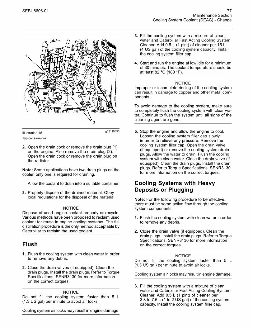
SEBU8606-01 77Maintenance Section
Cooling System Coolant (DEAC) - Change
g02119093Illustration 45Typical example
2. Open the drain cock or remove the drain plug (1)on the engine. Also remove the drain plug (2).Open the drain cock or remove the drain plug onthe radiator.
Note: Some applications have two drain plugs on thecooler, only one is required for draining.
Allow the coolant to drain into a suitable container.
3. Properly dispose of the drained material. Obeylocal regulations for the disposal of the material.
NOTICEDispose of used engine coolant properly or recycle.Various methods have been proposed to reclaim usedcoolant for reuse in engine cooling systems. The fulldistillation procedure is the only method acceptable byCaterpillar to reclaim the used coolant.
Flush1. Flush the cooling system with clean water in orderto remove any debris.
2. Close the drain valves (if equipped). Clean thedrain plugs. Install the drain plugs. Refer to TorqueSpecifications, SENR3130 for more informationon the correct torques.
NOTICEDo not fill the cooling system faster than 5 L(1.3 US gal) per minute to avoid air locks.
Cooling system air locksmay result in engine damage.
3. Fill the cooling system with a mixture of cleanwater and Caterpillar Fast Acting Cooling SystemCleaner. Add 0.5 L (1 pint) of cleaner per 15 L(4 US gal) of the cooling system capacity. Installthe cooling system filler cap.
4. Start and run the engine at low idle for a minimumof 30 minutes. The coolant temperature should beat least 82 °C (180 °F).
NOTICEImproper or incomplete rinsing of the cooling systemcan result in damage to copper and other metal com-ponents.
To avoid damage to the cooling system, make sureto completely flush the cooling system with clear wa-ter. Continue to flush the system until all signs of thecleaning agent are gone.
5. Stop the engine and allow the engine to cool.Loosen the cooling system filler cap slowlyin order to relieve any pressure. Remove thecooling system filler cap. Open the drain valve(if equipped) or remove the cooling system drainplugs. Allow the water to drain. Flush the coolingsystem with clean water. Close the drain valve (ifequipped). Clean the drain plugs. Install the drainplugs. Refer to Torque Specifications, SENR3130for more information on the correct torques.
Cooling Systems with HeavyDeposits or PluggingNote: For the following procedure to be effective,there must be some active flow through the coolingsystem components.
1. Flush the cooling system with clean water in orderto remove any debris.
2. Close the drain valve (if equipped). Clean thedrain plugs. Install the drain plugs. Refer to TorqueSpecifications, SENR3130 for more informationon the correct torques.
NOTICEDo not fill the cooling system faster than 5 L(1.3 US gal) per minute to avoid air locks.
Cooling system air locks may result in engine damage.
3. Fill the cooling system with a mixture of cleanwater and Caterpillar Fast Acting Cooling SystemCleaner. Add 0.5 L (1 pint) of cleaner per3.8 to 7.6 L (1 to 2 US gal) of the cooling systemcapacity. Install the cooling system filler cap.
78 SEBU8606-01Maintenance SectionCooling System Coolant (ELC) - Change
4. Start and run the engine at low idle for a minimumof 90 minutes. The coolant temperature should beat least 82 °C (180 °F).
NOTICEImproper or incomplete rinsing of the cooling systemcan result in damage to copper and other metal com-ponents.
To avoid damage to the cooling system, make sureto completely flush the cooling system with clear wa-ter. Continue to flush the system until all signs of thecleaning agent are gone.
5. Stop the engine and allow the engine to cool.Loosen the cooling system filler cap slowlyin order to relieve any pressure. Remove thecooling system filler cap. Open the drain valve(if equipped) or remove the cooling system drainplugs. Allow the water to drain. Flush the coolingsystem with clean water. Close the drain valve (ifequipped). Clean the drain plugs. Install the drainplugs. Refer to Torque Specifications, SENR3130for more information on the correct torques.
Fill
NOTICEDo not fill the cooling system faster than 5 L(1.3 US gal) per minute to avoid air locks.
Cooling system air locksmay result in engine damage.
1. Fill the cooling system with the coolant/antifreeze.Refer to this Operation and Maintenance Manual,“Refill Capacities and Recommendations” topic(Maintenance Section) for more information oncooling system specifications. Do not install thecooling system filler cap.
2. Start and run the engine at low idle. Increasethe engine rpm to high idle. Operate the enginein order to open the engine thermostat. Thisoperation will allow any air in the system to bepurged. Decrease the engine speed to low idle.Stop the engine.
3. Maintain the coolant level at the maximum markthat is correct for your application.
4. Clean the cooling system filler cap. Inspect thegasket that is on the cooling system filler cap.If the gasket that is on the cooling system fillercap is damaged, discard the old cooling systemfiller cap. Install a new cooling system filler cap.If the gasket that is on the cooling system fillercap is not damaged, perform a pressure test. A9S-8140 Pressurizing Pump is used to performthe pressure test. The correct pressure for thecooling system filler cap is stamped on the face ofthe cooling system filler cap. If the cooling systemfiller cap does not retain the correct pressure,install a new cooling system filler cap.
5. Start the engine. Inspect the cooling system forleaks and for the correct operating temperature.
i04261831
Cooling System Coolant (ELC)- ChangeSMCS Code: 1350-070; 1395-044
Clean the cooling system and flush the coolingsystem before the recommended maintenanceinterval if the following conditions exist:
• The engine overheats frequently.
• Foaming is observed.
• The oil has entered the cooling system and thecoolant is contaminated.
• The fuel has entered the cooling system and thecoolant is contaminated.
Note: When the cooling system is cleaned, onlyclean water is needed when the ELC is drained andreplaced.
Note: Inspect the water pump and the watertemperature regulator after the cooling system hasbeen drained. This inspection is a good opportunityto replace the water pump, the water temperatureregulator, and the hoses, if necessary.
NOTICEWhen any servicing or repair of the engine cool-ing system is performed, the procedure must beperformed with the engine on level ground. This pro-cedure will allow you to accurately check the coolantlevel. This procedure will also help in avoiding the riskof introducing an air lock into the coolant system.
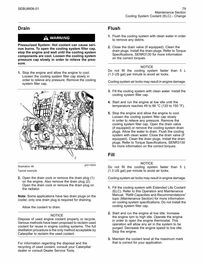
SEBU8606-01 79Maintenance Section
Cooling System Coolant (ELC) - Change
Drain
Pressurized System: Hot coolant can cause seri-ous burns. To open the cooling system filler cap,stop the engine and wait until the cooling systemcomponents are cool. Loosen the cooling systempressure cap slowly in order to relieve the pres-sure.
1. Stop the engine and allow the engine to cool.Loosen the cooling system filler cap slowly inorder to relieve any pressure. Remove the coolingsystem filler cap.
g02119093Illustration 46Typical example
2. Open the drain cock or remove the drain plug (1)on the engine. Also remove the drain plug (2).Open the drain cock or remove the drain plug onthe radiator.
Note: Some applications have two drain plugs on thecooler, only one drain plug is required for draining.
Allow the coolant to drain.
NOTICEDispose of used engine coolant properly or recycle.Various methods have been proposed to reclaim usedcoolant for reuse in engine cooling systems. The fulldistillation procedure is the only method acceptable byCaterpillar to reclaim the used coolant.
For information regarding the disposal and therecycling of used coolant, consult your Caterpillardealer or consult Dealer Service Tools.
Flush1. Flush the cooling system with clean water in orderto remove any debris.
2. Close the drain valve (if equipped). Clean thedrain plugs. Install the drain plugs. Refer to TorqueSpecifications, SENR3130 for more informationon the correct torques.
NOTICEDo not fill the cooling system faster than 5 L(1.3 US gal) per minute to avoid air locks.
Cooling system air locks may result in engine damage.
3. Fill the cooling system with clean water. Install thecooling system filler cap.
4. Start and run the engine at low idle until thetemperature reaches 49 to 66 °C (120 to 150 °F).
5. Stop the engine and allow the engine to cool.Loosen the cooling system filler cap slowlyin order to relieve any pressure. Remove thecooling system filler cap. Open the drain valve(if equipped) or remove the cooling system drainplugs. Allow the water to drain. Flush the coolingsystem with clean water. Close the drain valve (ifequipped). Clean the drain plugs. Install the drainplugs. Refer to Torque Specifications, SENR3130for more information on the correct torques.
Fill
NOTICEDo not fill the cooling system faster than 5 L(1.3 US gal) per minute to avoid air locks.
Cooling system air locks may result in engine damage.
1. Fill the cooling system with Extended Life Coolant(ELC). Refer to this Operation and MaintenanceManual, “Refill Capacities and Recommendations”topic (Maintenance Section) for more informationon cooling system specifications. Do not install thecooling system filler cap.
2. Start and run the engine at low idle. Increasethe engine rpm to high idle. Operate the enginein order to open the engine thermostat. Thisoperation will allow any air in the system to bepurged. Decrease the engine speed to low idle.Stop the engine.
3. Maintain the coolant level at the maximum markthat is correct for your application.

80 SEBU8606-01Maintenance SectionCooling System Coolant Extender (ELC) - Add
4. Clean the cooling system filler cap. Inspect thegasket that is on the cooling system filler cap. Ifthe gasket that is on the cooling system filler capis damaged, discard the old cooling system fillercap. Install a new cooling system filler cap. If thegasket that is on the cooling system filler cap isnot damaged, use a 9S-8140 Pressurizing Pumpin order to pressure test the cooling system fillercap. The correct pressure for the cooling systemfiller cap is stamped on the face of the coolingsystem filler cap. If the cooling system filler capdoes not retain the correct pressure, install a newcooling system filler cap.
5. Start the engine. Inspect the cooling system forleaks and for proper operating temperature.
i03644814
Cooling System CoolantExtender (ELC) - AddSMCS Code: 1352-045; 1395-081
Cat ELC (Extended Life Coolant) does not requirethe frequent additions of any supplemental coolingadditives which are associated with the presentconventional coolants. The Cat ELC Extender onlyneeds to be added once.
NOTICEUse only Cat Extended Life Coolant (ELC) Extenderwith Cat ELC.
Do NOT use conventional supplemental coolant addi-tive (SCA) with Cat ELC. Mixing Cat ELC with conven-tional coolants and/or conventional SCA reduces theCat ELC service life.
Check the cooling system only when the engine isstopped and cool.
Personal injury can result from hot coolant, steamand alkali.
At operating temperature, engine coolant is hotand under pressure. The radiator and all linesto heaters or the engine contain hot coolant orsteam. Any contact can cause severe burns.
Remove cooling system pressure cap slowly torelieve pressure only when engine is stopped andcooling system pressure cap is cool enough totouch with your bare hand.
Do not attempt to tighten hose connections whenthe coolant is hot, the hose can come off causingburns.
Cooling System Coolant Additive contains alkali.Avoid contact with skin and eyes.
NOTICECare must be taken to ensure that fluids are containedduring performance of inspection, maintenance, test-ing, adjusting and repair of the product. Be prepared tocollect the fluid with suitable containers before open-ing any compartment or disassembling any compo-nent containing fluids.
Refer to Special Publication, NENG2500, “CaterpillarDealer Service Tool Catalog” for tools and suppliessuitable to collect and contain fluids on Caterpillarproducts.
Dispose of all fluids according to local regulations andmandates.
NOTICEWhen any servicing or repair of the engine coolingsystem is performed the proceduremust be performedwith the engine on level ground. This will allow you toaccurately check the coolant level. This will also helpin avoiding the risk of introducing an air lock into thecoolant system.
1. Loosen the cooling system filler cap slowly inorder to relieve pressure. Remove the coolingsystem filler cap.
2. It may be necessary to drain enough coolant fromthe cooling system in order to add the Cat ELCExtender.
3. Add Cat ELC Extender according to therequirements for your engine's cooling systemcapacity. Refer to the Operation and MaintenanceManual, “Refill Capacities and Recommendations”article for more information.
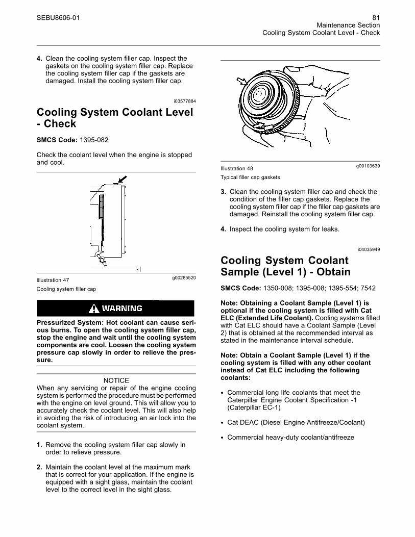
SEBU8606-01 81Maintenance Section
Cooling System Coolant Level - Check
4. Clean the cooling system filler cap. Inspect thegaskets on the cooling system filler cap. Replacethe cooling system filler cap if the gaskets aredamaged. Install the cooling system filler cap.
i03577884
Cooling System Coolant Level- CheckSMCS Code: 1395-082
Check the coolant level when the engine is stoppedand cool.
g00285520Illustration 47
Cooling system filler cap
Pressurized System: Hot coolant can cause seri-ous burns. To open the cooling system filler cap,stop the engine and wait until the cooling systemcomponents are cool. Loosen the cooling systempressure cap slowly in order to relieve the pres-sure.
NOTICEWhen any servicing or repair of the engine coolingsystem is performed the proceduremust be performedwith the engine on level ground. This will allow you toaccurately check the coolant level. This will also helpin avoiding the risk of introducing an air lock into thecoolant system.
1. Remove the cooling system filler cap slowly inorder to relieve pressure.
2. Maintain the coolant level at the maximum markthat is correct for your application. If the engine isequipped with a sight glass, maintain the coolantlevel to the correct level in the sight glass.
g00103639Illustration 48Typical filler cap gaskets
3. Clean the cooling system filler cap and check thecondition of the filler cap gaskets. Replace thecooling system filler cap if the filler cap gaskets aredamaged. Reinstall the cooling system filler cap.
4. Inspect the cooling system for leaks.
i04035949
Cooling System CoolantSample (Level 1) - ObtainSMCS Code: 1350-008; 1395-008; 1395-554; 7542
Note: Obtaining a Coolant Sample (Level 1) isoptional if the cooling system is filled with CatELC (Extended Life Coolant). Cooling systems filledwith Cat ELC should have a Coolant Sample (Level2) that is obtained at the recommended interval asstated in the maintenance interval schedule.
Note: Obtain a Coolant Sample (Level 1) if thecooling system is filled with any other coolantinstead of Cat ELC including the followingcoolants:
• Commercial long life coolants that meet theCaterpillar Engine Coolant Specification -1(Caterpillar EC-1)
• Cat DEAC (Diesel Engine Antifreeze/Coolant)
• Commercial heavy-duty coolant/antifreeze
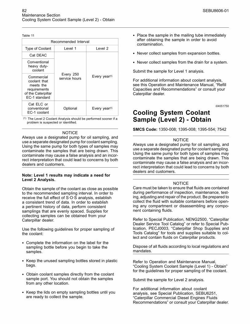
82 SEBU8606-01Maintenance SectionCooling System Coolant Sample (Level 2) - Obtain
Table 11
Recommended Interval
Type of Coolant Level 1 Level 2
Cat DEAC
Conventionalheavy duty-coolant
Commercialcoolant thatmeets therequirements
of the CaterpillarEC-1 standard
Every 250service hours Every year(1)
Cat ELC orconventionalEC-1 coolant
Optional Every year(1)
(1) The Level 2 Coolant Analysis should be performed sooner if aproblem is suspected or identified.
NOTICEAlways use a designated pump for oil sampling, anduse a separate designated pump for coolant sampling.Using the same pump for both types of samples maycontaminate the samples that are being drawn. Thiscontaminate may cause a false analysis and an incor-rect interpretation that could lead to concerns by bothdealers and customers.
Note: Level 1 results may indicate a need forLevel 2 Analysis.
Obtain the sample of the coolant as close as possibleto the recommended sampling interval. In order toreceive the full effect of S·O·S analysis, establisha consistent trend of data. In order to establisha pertinent history of data, perform consistentsamplings that are evenly spaced. Supplies forcollecting samples can be obtained from yourCaterpillar dealer.
Use the following guidelines for proper sampling ofthe coolant:
• Complete the information on the label for thesampling bottle before you begin to take thesamples.
• Keep the unused sampling bottles stored in plasticbags.
• Obtain coolant samples directly from the coolantsample port. You should not obtain the samplesfrom any other location.
• Keep the lids on empty sampling bottles until youare ready to collect the sample.
• Place the sample in the mailing tube immediatelyafter obtaining the sample in order to avoidcontamination.
• Never collect samples from expansion bottles.
• Never collect samples from the drain for a system.
Submit the sample for Level 1 analysis.
For additional information about coolant analysis,see this Operation and Maintenance Manual, “RefillCapacities and Recommendations” or consult yourCaterpillar dealer.
i04051750
Cooling System CoolantSample (Level 2) - ObtainSMCS Code: 1350-008; 1395-008; 1395-554; 7542
NOTICEAlways use a designated pump for oil sampling, anduse a separate designated pump for coolant sampling.Using the same pump for both types of samples maycontaminate the samples that are being drawn. Thiscontaminate may cause a false analysis and an incor-rect interpretation that could lead to concerns by bothdealers and customers.
NOTICECare must be taken to ensure that fluids are containedduring performance of inspection, maintenance, test-ing, adjusting and repair of the product. Be prepared tocollect the fluid with suitable containers before open-ing any compartment or disassembling any compo-nent containing fluids.
Refer to Special Publication, NENG2500, “CaterpillarDealer Service Tool Catalog” or refer to Special Pub-lication, PECJ0003, “Caterpillar Shop Supplies andTools Catalog” for tools and supplies suitable to col-lect and contain fluids on Caterpillar products.
Dispose of all fluids according to local regulations andmandates.
Refer to Operation and Maintenance Manual,“Cooling System Coolant Sample (Level 1) - Obtain”for the guidelines for proper sampling of the coolant.
Submit the sample for Level 2 analysis.
For additional information about coolantanalysis, see Special Publication, SEBU6251,“Caterpillar Commercial Diesel Engines FluidsRecommendations” or consult your Caterpillar dealer.
SEBU8606-01 83Maintenance Section
Cooling System Supplemental Coolant Additive (SCA) - Test/Add
i03644817
Cooling System SupplementalCoolant Additive (SCA) -Test/AddSMCS Code: 1352-045; 1395-081
Cooling system coolant additive contains alkali.To help prevent personal injury, avoid contact withthe skin and the eyes. Do not drink cooling systemcoolant additive.
Note: Test the concentration of the SupplementalCoolant Additive (SCA) or test the SCA concentrationas part of an S·O·S Coolant Analysis.
Test for SCA Concentration
Coolant and SCA
NOTICEDo not exceed the recommended six percent supple-mental coolant additive concentration.
Use the 8T-5296 Coolant Conditioner Test Kitor use the 4C-9301 Coolant Conditioner Test Kitin order to check the concentration of the SCA.Refer to this Operation and Maintenance Manual,“Refill Capacities and Recommendations” for moreinformation.
Water and SCA
NOTICEDo not exceed the recommended eight percent sup-plemental coolant additive concentration.
Test the concentration of the SCA with the 8T-5296Coolant Conditioner Test Kit. Refer to the SpecialPublication, SEBU6251, “Caterpillar CommercialDiesel Engine Fluids Recommendations” for moreinformation.
S·O·S Coolant AnalysisS·O·S coolant samples can be analyzed at yourCaterpillar dealer. S·O·S Coolant Analysis is aprogram that is based on periodic samples.
Level 1
Level 1 is a basic analysis of the coolant. Thefollowing items are tested:
• Glycol Concentration
• Concentration of SCA
• pH
• Conductivity
The results are reported, and recommendationsare made according to the results. Consult yourCaterpillar dealer for information on the benefits ofmanaging your equipment with an S·O·S CoolantAnalysis.
Level 2
This level coolant analysis is recommended when theengine is overhauled. Refer to this Operations andMaintenance Manual, “Overhaul Considerations” forfurther information.
Add the SCA, If Necessary
NOTICEDo not exceed the recommended amount of sup-plemental coolant additive concentration. Excessivesupplemental coolant additive concentration can formdeposits on the higher temperature surfaces of thecooling system, reducing the engine's heat transfercharacteristics. Reduced heat transfer could causecracking of the cylinder head and other high temper-ature components. Excessive supplemental coolantadditive concentration could also result in radiatortube blockage, overheating, and/or accelerated waterpump seal wear. Never use both liquid supplementalcoolant additive and the spin-on element (if equipped)at the same time. The use of those additives togethercould result in supplemental coolant additive concen-tration exceeding the recommended maximum.
Pressurized System: Hot coolant can cause seri-ous burns. To open the cooling system filler cap,stop the engine and wait until the cooling systemcomponents are cool. Loosen the cooling systempressure cap slowly in order to relieve the pres-sure.
NOTICEWhen any servicing or repair of the engine coolingsystem is performed the proceduremust be performedwith the engine on level ground. This will allow you toaccurately check the coolant level. This will also helpin avoiding the risk of introducing an air lock into thecoolant system.
84 SEBU8606-01Maintenance SectionEngine - Clean
1. Slowly loosen the cooling system filler cap inorder to relieve the pressure. Remove the coolingsystem filler cap.
Note: Always discard drained fluids according tolocal regulations.
2. If necessary, drain some coolant from the coolingsystem into a suitable container in order to allowspace for the extra SCA.
3. Add the proper amount of SCA. Referto the Special Publication, SEBU6251,“Caterpillar Commercial Diesel Engines FluidsRecommendations” for more information on SCArequirements.
4. Clean the cooling system filler cap. Inspect thegaskets of the cooling system filler cap. If thegaskets are damaged, replace the old coolingsystem filler cap with a new cooling system fillercap. Install the cooling system filler cap.
i03991933
Engine - CleanSMCS Code: 1000-070
Personal injury or death can result from high volt-age.
Moisture can create paths of electrical conductiv-ity.
Make sure that the electrical system is OFF. Lockout the starting controls and tag the controls “DONOT OPERATE”.
NOTICEAccumulated grease and oil on an engine is a fire haz-ard. Keep the engine clean. Remove debris and fluidspills whenever a significant quantity accumulates onthe engine.
Periodic cleaning of the engine is recommended.Steam cleaning the engine will remove accumulatedoil and grease. A clean engine provides the followingbenefits:
• Easy detection of fluid leaks
• Maximum heat transfer characteristics
• Ease of maintenance
Note: Caution must be used in order to preventelectrical components from being damaged byexcessive water when the engine is cleaned.Pressure washers and steam cleaners should not bedirected at any electrical connectors or the junction ofcables into the rear of the connectors. Avoid electricalcomponents such as the alternator, the starter, andthe ECM. Protect the fuel injection pump from fluidsin order to wash the engine.
AftertreatmentDuring the engine cleaning process, ensurethat water or cleaning fluids cannot enter theaftertreatment system. If cleaning fluids enters theaftertreatment system, damage could occur.
i01553486
Engine Air Cleaner Element(Dual Element) - Clean/ReplaceSMCS Code: 1054-037; 1054-510
NOTICENever run the engine without an air cleaner elementinstalled. Never run the engine with a damaged aircleaner element. Do not use air cleaner elements withdamaged pleats, gaskets or seals. Dirt entering theengine causes premature wear and damage to enginecomponents. Air cleaner elements help to prevent air-borne debris from entering the air inlet.
NOTICENever service the air cleaner element with the enginerunning since this will allow dirt to enter the engine.
Servicing the Air Cleaner ElementsIf the air cleaner element becomes plugged, the aircan split the material of the air cleaner element.Unfiltered air will drastically accelerate internal enginewear. Your Caterpillar dealer has the proper aircleaner elements for your application. Consult yourCaterpillar dealer for the correct air cleaner element.
• Check the precleaner (if equipped) daily foraccumulation of dirt and debris. Remove any dirtand debris, as needed.
• Operating conditions (dust, dirt and debris) mayrequire more frequent service of the air cleanerelement.
• The air cleaner element may be cleaned up tosix times if the element is properly cleaned andinspected.

SEBU8606-01 85Maintenance Section
Engine Air Cleaner Element (Dual Element) - Clean/Replace
• The air cleaner element should be replaced at leastone time per year. This replacement should beperformed regardless of the number of cleanings.
Replace the dirty paper air cleaner elements withclean air cleaner elements. Before installation, theair cleaner elements should be thoroughly checkedfor tears and/or holes in the filter material. Inspectthe gasket or the seal of the air cleaner element fordamage. Maintain a supply of suitable air cleanerelements for replacement purposes.
Dual Element Air Cleaners
The dual element air cleaner contains a primaryair cleaner element and a secondary air cleanerelement. The primary air cleaner element can beused up to six times if the element is properly cleanedand inspected. The primary air cleaner elementshould be replaced at least one time per year. Thisreplacement should be performed regardless of thenumber of cleanings.
The secondary air cleaner element is not serviceableor washable. The secondary air cleaner elementshould be removed and discarded for every threecleanings of the primary air cleaner element. Whenthe engine is operating in environments that aredusty or dirty, air cleaner elements may require morefrequent replacement.
g00736431Illustration 49
(1) Cover(2) Primary air cleaner element(3) Secondary air cleaner element(4) Turbocharger air inlet
1. Remove the cover. Remove the primary aircleaner element.
2. The secondary air cleaner element should beremoved and discarded for every three cleaningsof the primary air cleaner element.
Note: Refer to “Cleaning the Primary Air CleanerElements”.
3. Cover the turbocharger air inlet with tape in orderto keep dirt out.
4. Clean the inside of the air cleaner cover and bodywith a clean, dry cloth.
5. Remove the tape for the turbocharger air inlet.Install the secondary air cleaner element. Install aprimary air cleaner element that is new or cleaned.
6. Install the air cleaner cover.
7. Reset the air cleaner service indicator.
Cleaning the Primary Air CleanerElements
NOTICECaterpillar recommends certified air filter cleaning ser-vices that are available at Caterpillar dealers. TheCaterpillar cleaning process uses proven proceduresto assure consistent quality and sufficient filter life.
Observe the following guidelines if you attempt toclean the filter element:
Do not tap or strike the filter element in order to re-move dust.
Do not wash the filter element.
Use low pressure compressed air in order to removethe dust from the filter element. Air pressure must notexceed 207 kPa (30 psi). Direct the air flow up thepleats and down the pleats from the inside of the filterelement. Take extreme care in order to avoid damageto the pleats.
Do not use air filters with damaged pleats, gaskets, orseals. Dirt entering the engine will cause damage toengine components.
The primary air cleaner element can be used upto six times if the element is properly cleaned andinspected. When the primary air cleaner element iscleaned, check for rips or tears in the filter material.The primary air cleaner element should be replacedat least one time per year. This replacement shouldbe performed regardless of the number of cleanings.
Use clean primary air cleaner elements while dirtyelements are being cleaned.
NOTICEDo not clean the air cleaner elements by bumping ortapping. This could damage the seals. Do not use el-ements with damaged pleats, gaskets or seals. Dam-aged elements will allow dirt to pass through. Enginedamage could result.

86 SEBU8606-01Maintenance SectionEngine Air Cleaner Element (Dual Element) - Clean/Replace
Visually inspect the primary air cleaner elementsbefore cleaning. Inspect the air cleaner elements fordamage to the seal, the gaskets, and the outer cover.Discard any damaged air cleaner elements.
There are two common methods that are used toclean primary air cleaner elements:
• Pressurized air
• Vacuum cleaning
Pressurized Air
Pressurized air can be used to clean primary aircleaner elements that have not been cleaned morethan two times. Pressurized air will not removedeposits of carbon and oil. Use filtered, dry air with amaximum pressure of 207 kPa (30 psi).
g00281692Illustration 50
Note: When the primary air cleaner elements arecleaned, always begin with the clean side (inside)in order to force dirt particles toward the dirty side(outside).
Aim the hose so that the air flows inside the elementalong the length of the filter in order to help preventdamage to the paper pleats. Do not aim the streamof air directly at the primary air cleaner element. Dirtcould be forced further into the pleats.
Note: Refer to “Inspecting the Primary Air CleanerElements”.
Vacuum Cleaning
Vacuum cleaning is a good method for cleaningprimary air cleaner elements which require dailycleaning because of a dry, dusty environment.Cleaning with pressurized air is recommended priorto vacuum cleaning. Vacuum cleaning will not removedeposits of carbon and oil.
Note: Refer to “Inspecting the Primary Air CleanerElements”.
Inspecting the Primary Air CleanerElements
g00281693Illustration 51
Inspect the clean, dry primary air cleaner element.Use a 60 watt blue light in a dark room or in a similarfacility. Place the blue light in the primary air cleanerelement. Rotate the primary air cleaner element.Inspect the primary air cleaner element for tearsand/or holes. Inspect the primary air cleaner elementfor light that may show through the filter material. If itis necessary in order to confirm the result, comparethe primary air cleaner element to a new primary aircleaner element that has the same part number.
Do not use a primary air cleaner element that hasany tears and/or holes in the filter material. Do notuse a primary air cleaner element with damagedpleats, gaskets or seals. Discard damaged primaryair cleaner elements.
Storing Primary Air Cleaner Elements
If a primary air cleaner element that passes inspectionwill not be used, the primary air cleaner element canbe stored for future use.
g00281694Illustration 52

SEBU8606-01 87Maintenance Section
Engine Air Cleaner Element (Single Element) - Inspect/Replace
Do not use paint, a waterproof cover, or plastic as aprotective covering for storage. An airflow restrictionmay result. To protect against dirt and damage, wrapthe primary air cleaner elements in Volatile CorrosionInhibited (VCI) paper.
Place the primary air cleaner element into a boxfor storage. For identification, mark the outside ofthe box and mark the primary air cleaner element.Include the following information:
• Date of cleaning
• Number of cleanings
Store the box in a dry location.
i01432811
Engine Air CleanerElement (Single Element) -Inspect/ReplaceSMCS Code: 1054-040; 1054-510
Perform the Operation and Maintenance Manual,“Engine Air Cleaner Service Indicator-Inspect”procedure and perform the Operation andMaintenance Manual, “Engine Air PrecleanerCheck/Clean” procedure (if equipped) beforeperforming the following procedure.
NOTICENever run the engine without an air cleaner elementinstalled. Never run the engine with a damaged aircleaner element. Do not use air cleaner elements withdamaged pleats, gaskets or seals. Dirt entering theengine causes premature wear and damage to enginecomponents. Air cleaner elements help to prevent air-borne debris from entering the air inlet.
NOTICENever service the air cleaner element with the enginerunning since this will allow dirt to enter the engine.
g00310664Illustration 53(1) Air cleaner cover(2) Air filter element(3) Air inlet
1. Remove air cleaner cover (1) and remove air filterelement (2).
2. Cover air inlet (3) with tape or a clean cloth so thatdebris cannot enter the air inlet.
3. Clean the inside of air cleaner cover (1). Clean thebody that holds the air cleaner element.
4. Inspect the replacement element for the followingitems:damage, dirt, and debris.
5. Remove the seal from the opening of the air inlet.
6. Install a clean, undamaged air filter element (2).
7. Install air cleaner cover (1).
8. Reset the air cleaner service indicator.
i02242500
Engine Air Cleaner Element(Single Element) - ReplaceSMCS Code: 1051; 1054-510
NOTICENever service the air cleaner element with the enginerunning since this will allow dirt to enter the engine.
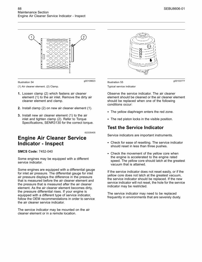
88 SEBU8606-01Maintenance SectionEngine Air Cleaner Service Indicator - Inspect
g00109823Illustration 54(1) Air cleaner element. (2) Clamp.
1. Loosen clamp (2) which fastens air cleanerelement (1) to the air inlet. Remove the dirty aircleaner element and clamp.
2. Install clamp (2) on new air cleaner element (1).
3. Install new air cleaner element (1) to the airinlet and tighten clamp (2). Refer to TorqueSpecifications, SENR3130 for the correct torque.
i02335405
Engine Air Cleaner ServiceIndicator - InspectSMCS Code: 7452-040
Some engines may be equipped with a differentservice indicator.
Some engines are equipped with a differential gaugefor inlet air pressure. The differential gauge for inletair pressure displays the difference in the pressurethat is measured before the air cleaner element andthe pressure that is measured after the air cleanerelement. As the air cleaner element becomes dirty,the pressure differential rises. If your engine isequipped with a different type of service indicator,follow the OEM recommendations in order to servicethe air cleaner service indicator.
The service indicator may be mounted on the aircleaner element or in a remote location.
g00103777Illustration 55Typical service indicator
Observe the service indicator. The air cleanerelement should be cleaned or the air cleaner elementshould be replaced when one of the followingconditions occur:
• The yellow diaphragm enters the red zone.
• The red piston locks in the visible position.
Test the Service IndicatorService indicators are important instruments.
• Check for ease of resetting. The service indicatorshould reset in less than three pushes.
• Check the movement of the yellow core whenthe engine is accelerated to the engine ratedspeed. The yellow core should latch at the greatestvacuum that is attained.
If the service indicator does not reset easily, or if theyellow core does not latch at the greatest vacuum,the service indicator should be replaced. If the newservice indicator will not reset, the hole for the serviceindicator may be restricted.
The service indicator may need to be replacedfrequently in environments that are severely dusty.

SEBU8606-01 89Maintenance Section
Engine Air Precleaner - Check/Clean
i02927289
Engine Air Precleaner -Check/CleanSMCS Code: 1055-070; 1055-535
g01453058Illustration 56
Typical engine air precleaner(1) Wing nut(2) Cover(3) Body
Remove wing nut (1) and cover (2). Check for anaccumulation of dirt and debris in body (3). Clean thebody, if necessary.
After cleaning the precleaner, install cover (2) andwing nut (1).
Note: When the engine is operated in dustyapplications, more frequent cleaning is required.
i04246290
Engine Crankcase BreatherElement - ReplaceSMCS Code: 1317-510-FQ
Hot oil and hot components can cause personalinjury. Do not allow hot oil or hot components tocontact the skin.
NOTICEEnsure that the engine is stopped before any servicingor repair is performed.
NOTICECare must be taken to ensure that fluids are containedduring performance of inspection, maintenance, test-ing, adjusting, and repair of the product. Be preparedto collect the fluid with suitable containers beforeopening any compartment or disassembling any com-ponent containing fluids.
Refer to Special Publication, NENG2500, “Cat DealerService Tool Catalog” or refer to Special Publication,PECJ0003, “Cat Shop Supplies and Tools Catalog” fortools and supplies suitable to collect and contain fluidson Cat products.
Dispose of all fluids according to local regulations andmandates.
The crankcase breather is a very importantcomponent in order to keep your engine emissionscompliant.
• The filter element within the crankcase breathermust be serviced at the prescribed service interval.
• The correct filter element must be installed beforethe engine is operated.
• The installation of the filter element is veryimportant.
• The quality of the filter element that is installed isvery important.
• The filter element protects the engine fromexcessive quantities of oil from entering theinduction system. The filter element also protectsthe engine aftertreatment system.
Note: Excessive quantities of oil that enter theinduction system of the engine can rapidly increasethe engine speed without control.
For information on aftermarket products, referto Operation and Maintenance Manual, “EngineDescription”. Within that section, refer to the title“Aftermarket Products and Caterpillar Engines”.

90 SEBU8606-01Maintenance SectionEngine Crankcase Breather Element - Replace
g02415998Illustration 57Typical example
1. Ensure that dirt cannot enter the breatherassembly. Ensure that the outside body of thebreather assembly is clean and free from damage.Place a container under the breather assembly.
2. Rotate the cap (1) counterclockwise into theunlocked position. Remove the cap from the bodyof the breather (3).
3. Note the orientation of the filter element (2).Remove the filter element .
g01884135Illustration 58
(B) Alignment position
Note: The cut away from section (5) in the cap allowsaccess to the seal.
4. Remove the old seal (4) and install a new seal.
5. Install a new filter element into the breather body(3) and orient the filter element so that position (A)is aligned. Refer to illustration 57. Align position(A) on the filter element to position (B) on the cap.
g02415999Illustration 59
Typical example
6. Install the cap (1). Rotate the cap by handclockwise until the cap locks into the lockedposition C on the breather body.
7. Remove the container.
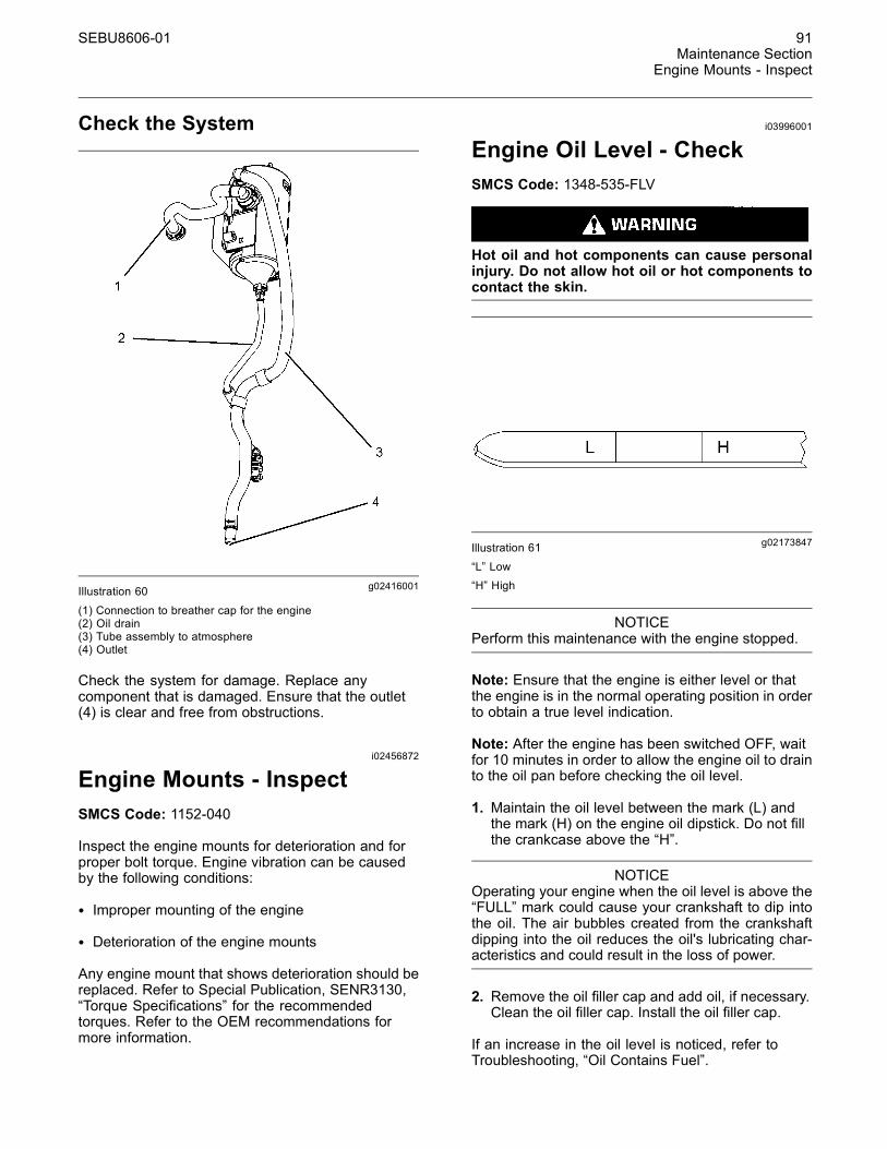
SEBU8606-01 91Maintenance Section
Engine Mounts - Inspect
Check the System
g02416001Illustration 60
(1) Connection to breather cap for the engine(2) Oil drain(3) Tube assembly to atmosphere(4) Outlet
Check the system for damage. Replace anycomponent that is damaged. Ensure that the outlet(4) is clear and free from obstructions.
i02456872
Engine Mounts - InspectSMCS Code: 1152-040
Inspect the engine mounts for deterioration and forproper bolt torque. Engine vibration can be causedby the following conditions:
• Improper mounting of the engine
• Deterioration of the engine mounts
Any engine mount that shows deterioration should bereplaced. Refer to Special Publication, SENR3130,“Torque Specifications” for the recommendedtorques. Refer to the OEM recommendations formore information.
i03996001
Engine Oil Level - CheckSMCS Code: 1348-535-FLV
Hot oil and hot components can cause personalinjury. Do not allow hot oil or hot components tocontact the skin.
g02173847Illustration 61
“L” Low“H” High
NOTICEPerform this maintenance with the engine stopped.
Note: Ensure that the engine is either level or thatthe engine is in the normal operating position in orderto obtain a true level indication.
Note: After the engine has been switched OFF, waitfor 10 minutes in order to allow the engine oil to drainto the oil pan before checking the oil level.
1. Maintain the oil level between the mark (L) andthe mark (H) on the engine oil dipstick. Do not fillthe crankcase above the “H”.
NOTICEOperating your engine when the oil level is above the“FULL” mark could cause your crankshaft to dip intothe oil. The air bubbles created from the crankshaftdipping into the oil reduces the oil's lubricating char-acteristics and could result in the loss of power.
2. Remove the oil filler cap and add oil, if necessary.Clean the oil filler cap. Install the oil filler cap.
If an increase in the oil level is noticed, refer toTroubleshooting, “Oil Contains Fuel”.
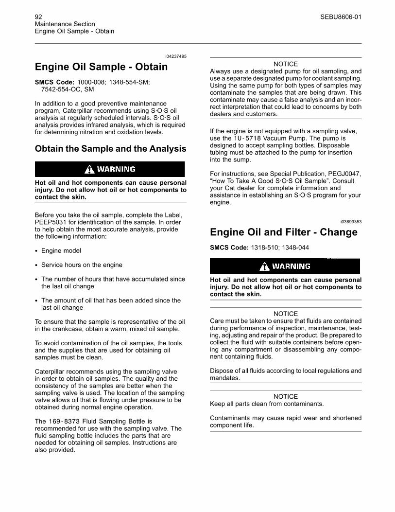
92 SEBU8606-01Maintenance SectionEngine Oil Sample - Obtain
i04237495
Engine Oil Sample - ObtainSMCS Code: 1000-008; 1348-554-SM;7542-554-OC, SM
In addition to a good preventive maintenanceprogram, Caterpillar recommends using S·O·S oilanalysis at regularly scheduled intervals. S·O·S oilanalysis provides infrared analysis, which is requiredfor determining nitration and oxidation levels.
Obtain the Sample and the Analysis
Hot oil and hot components can cause personalinjury. Do not allow hot oil or hot components tocontact the skin.
Before you take the oil sample, complete the Label,PEEP5031 for identification of the sample. In orderto help obtain the most accurate analysis, providethe following information:
• Engine model
• Service hours on the engine
• The number of hours that have accumulated sincethe last oil change
• The amount of oil that has been added since thelast oil change
To ensure that the sample is representative of the oilin the crankcase, obtain a warm, mixed oil sample.
To avoid contamination of the oil samples, the toolsand the supplies that are used for obtaining oilsamples must be clean.
Caterpillar recommends using the sampling valvein order to obtain oil samples. The quality and theconsistency of the samples are better when thesampling valve is used. The location of the samplingvalve allows oil that is flowing under pressure to beobtained during normal engine operation.
The 169-8373 Fluid Sampling Bottle isrecommended for use with the sampling valve. Thefluid sampling bottle includes the parts that areneeded for obtaining oil samples. Instructions arealso provided.
NOTICEAlways use a designated pump for oil sampling, anduse a separate designated pump for coolant sampling.Using the same pump for both types of samples maycontaminate the samples that are being drawn. Thiscontaminate may cause a false analysis and an incor-rect interpretation that could lead to concerns by bothdealers and customers.
If the engine is not equipped with a sampling valve,use the 1U-5718 Vacuum Pump. The pump isdesigned to accept sampling bottles. Disposabletubing must be attached to the pump for insertioninto the sump.
For instructions, see Special Publication, PEGJ0047,“How To Take A Good S·O·S Oil Sample”. Consultyour Cat dealer for complete information andassistance in establishing an S·O·S program for yourengine.
i03899353
Engine Oil and Filter - ChangeSMCS Code: 1318-510; 1348-044
Hot oil and hot components can cause personalinjury. Do not allow hot oil or hot components tocontact the skin.
NOTICECare must be taken to ensure that fluids are containedduring performance of inspection, maintenance, test-ing, adjusting and repair of the product. Be prepared tocollect the fluid with suitable containers before open-ing any compartment or disassembling any compo-nent containing fluids.
Dispose of all fluids according to local regulations andmandates.
NOTICEKeep all parts clean from contaminants.
Contaminants may cause rapid wear and shortenedcomponent life.

SEBU8606-01 93Maintenance Section
Engine Oil and Filter - Change
Do not drain the engine lubricating oil when theengine is cold. As the engine lubricating oil cools,suspended waste particles settle on the bottom ofthe oil pan. The waste particles are not removed withdraining cold oil. Drain the oil pan with the enginestopped. Drain the oil pan with the oil warm. Thisdraining method allows the waste particles that aresuspended in the oil to be drained properly.
Failure to follow this recommended procedure willcause the waste particles to be recirculated throughthe engine lubrication system with the new oil.
Drain the Engine Lubricating OilNote: Ensure that the vessel that will be used is largeenough to collect the waste oil.
After the engine has been run at the normal operatingtemperature, stop the engine. Use one of thefollowing methods to drain the engine oil pan:
g02131361Illustration 62
• If the engine is equipped with a drain valve (2),turn the drain valve knob counterclockwise in orderto drain the oil. After the oil has drained, turn thedrain valve knob clockwise in order to close thedrain valve.
• If the engine is not equipped with a drain valve,remove the oil drain plug (1) in order to allow the oilto drain. If the engine is equipped with a shallow oilpan, remove the bottom oil drain plugs from bothends of the oil pan.
After the oil has drained, the oil drain plug should becleaned and installed. If necessary, replace the Oring seal. Tighten the drain plug to 34 N·m (25 lb ft).
Remove the container and disposal of the waste oilin accordance with local regulations.
Replace the Oil Filter
NOTICECaterpillar oil filters are manufactured to Caterpillarspecifications. Use of an oil filter that is not recom-mended by Caterpillar could result in severe damageto the engine bearings, crankshaft, etc, as a result ofthe larger waste particles from unfiltered oil enteringthe engine lubricating system. Only use oil filters rec-ommended by Caterpillar.
1. Place a suitable container below the oil filterassembly. Remove the oil filter with a 1U-8760Chain Wrench.
Note: The following actions can be carried out aspart of the preventive maintenance program.
g01999595Illustration 63Element with debris
2. Cut the oil filter open with a 175-7546 Oil FilterCutter . Break apart the pleats and inspect theoil filter for metal debris. An excessive amountof metal debris in the oil filter may indicate earlywear or a pending failure.
Use a magnet to differentiate between the ferrousmetals and the nonferrous metals that are found inthe oil filter element. Ferrous metals may indicatewear on the steel and cast iron parts of the engine.
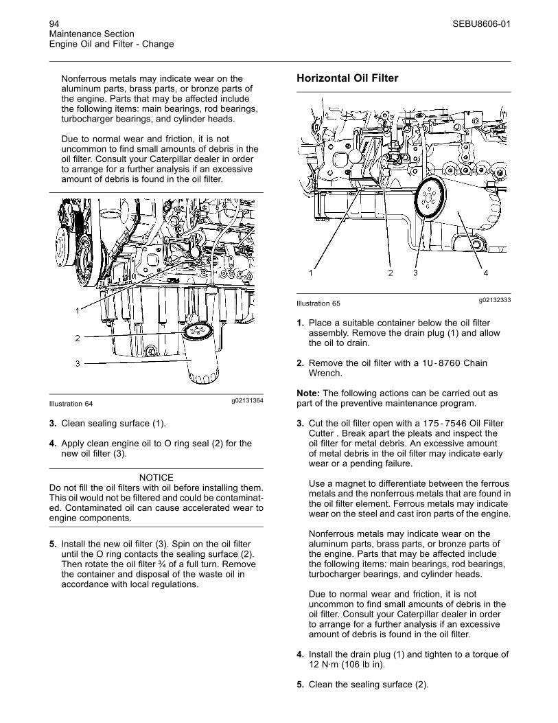
94 SEBU8606-01Maintenance SectionEngine Oil and Filter - Change
Nonferrous metals may indicate wear on thealuminum parts, brass parts, or bronze parts ofthe engine. Parts that may be affected includethe following items: main bearings, rod bearings,turbocharger bearings, and cylinder heads.
Due to normal wear and friction, it is notuncommon to find small amounts of debris in theoil filter. Consult your Caterpillar dealer in orderto arrange for a further analysis if an excessiveamount of debris is found in the oil filter.
g02131364Illustration 64
3. Clean sealing surface (1).
4. Apply clean engine oil to O ring seal (2) for thenew oil filter (3).
NOTICEDo not fill the oil filters with oil before installing them.This oil would not be filtered and could be contaminat-ed. Contaminated oil can cause accelerated wear toengine components.
5. Install the new oil filter (3). Spin on the oil filteruntil the O ring contacts the sealing surface (2).Then rotate the oil filter ¾ of a full turn. Removethe container and disposal of the waste oil inaccordance with local regulations.
Horizontal Oil Filter
g02132333Illustration 65
1. Place a suitable container below the oil filterassembly. Remove the drain plug (1) and allowthe oil to drain.
2. Remove the oil filter with a 1U-8760 ChainWrench.
Note: The following actions can be carried out aspart of the preventive maintenance program.
3. Cut the oil filter open with a 175-7546 Oil FilterCutter . Break apart the pleats and inspect theoil filter for metal debris. An excessive amountof metal debris in the oil filter may indicate earlywear or a pending failure.
Use a magnet to differentiate between the ferrousmetals and the nonferrous metals that are found inthe oil filter element. Ferrous metals may indicatewear on the steel and cast iron parts of the engine.
Nonferrous metals may indicate wear on thealuminum parts, brass parts, or bronze parts ofthe engine. Parts that may be affected includethe following items: main bearings, rod bearings,turbocharger bearings, and cylinder heads.
Due to normal wear and friction, it is notuncommon to find small amounts of debris in theoil filter. Consult your Caterpillar dealer in orderto arrange for a further analysis if an excessiveamount of debris is found in the oil filter.
4. Install the drain plug (1) and tighten to a torque of12 N·m (106 lb in).
5. Clean the sealing surface (2).

SEBU8606-01 95Maintenance Section
Fan Clearance - Check
NOTICEDo not fill the oil filters with oil before installing them.This oil would not be filtered and could be contaminat-ed. Contaminated oil can cause accelerated wear toengine components.
6. Apply clean engine oil to O ring seal (3) for thenew oil filter (4).
7. Install the new oil filter. Spin on the oil filter (4)until the O ring contacts the sealing surface (2).Then rotate the oil filter ¾ of a full turn. Removethe container and disposal of the waste oil inaccordance with local regulations.
Fill the Oil Pan1. Remove the oil filler cap. Refer to thisOperation and Maintenance Manual, “FluidRecommendations” for more information onsuitable oils. Fill the oil pan with the correctamount of new engine lubricating oil. Referto this Operation and Maintenance Manual,“Refill Capacities” for more information on refillcapacities.
NOTICEIf equipped with an auxiliary oil filter system or a re-mote filter system, follow the OEM or the filter manu-factures recommendations. Under filling or over fillingthe crankcase with oil can cause engine damage.
2. Start the engine and run the engine at “LOWIDLE” for 2 minutes. Perform this procedure inorder to ensure that the lubrication system hasoil and that the oil filters are filled. Inspect the oilfilter for oil leaks.
3. Stop the engine and allow the oil to drain back tothe oil pan for a minimum of 10 minutes.
g02173847Illustration 66“L” Low“H” High
4. Remove the engine oil level gauge in order tocheck the oil level. Maintain the oil level between“L” and “H” marks on the engine oil level gauge.Do not fill the crankcase above the “H” mark.
i04323342
Fan Clearance - CheckSMCS Code: 1356; 1359; 1360
There are different types of cooling systems. Refer tothe OEM for information on clearance for the fan.
Ensure that the engine is stopped. Ensure that thecooling system is full. The clearance between thecover (1) and the fan (2) will require checking. Thegap (A) between the edge of the cover and the tip ofthe fan blade must be checked in four equally spacedpositions.

96 SEBU8606-01Maintenance SectionFuel System - Prime
g02479476Illustration 67
Typical example
Adjustment of the cover will change the clearance(gap) between the edge of the cover and the tip ofthe fan blade. Ensure that the cover is centralized tothe fan.
The maximum clearance is 18 mm (0.71 inch). Theminimum clearance is 10 mm (0.39 inch).
i03906114
Fuel System - PrimeSMCS Code: 1258-548
Note: Refer to Systems Operation, Testing,and Adjusting, “Cleanliness of Fuel SystemComponents” for detailed information on thestandards of cleanliness that must be observedduring ALL work on the fuel system.
Ensure that all adjustments and repairs are performedby authorized personnel that have had the correcttraining.
NOTICEDo not crank the engine continuously for more than30 seconds. Allow the starting motor to cool for twominutes before cranking the engine again.
If air enters the fuel system, the air must be purgedfrom the fuel system before the engine can bestarted. Air can enter the fuel system when thefollowing events occur:
• The fuel tank is empty or the fuel tank has beenpartially drained.
• The low-pressure fuel lines are disconnected.
• A leak exists in the low-pressure fuel system.
• The fuel filter has been replaced.
Use the following procedures in order to remove airfrom the fuel system:
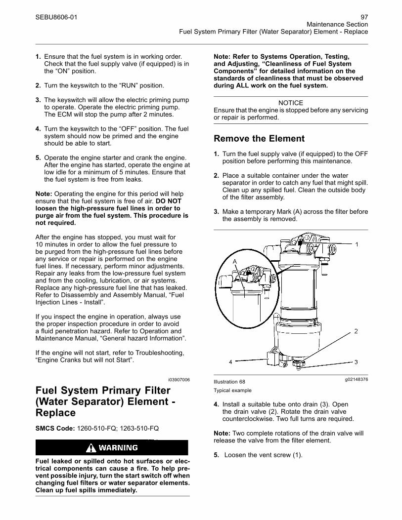
SEBU8606-01 97Maintenance Section
Fuel System Primary Filter (Water Separator) Element - Replace
1. Ensure that the fuel system is in working order.Check that the fuel supply valve (if equipped) is inthe “ON” position.
2. Turn the keyswitch to the “RUN” position.
3. The keyswitch will allow the electric priming pumpto operate. Operate the electric priming pump.The ECM will stop the pump after 2 minutes.
4. Turn the keyswitch to the “OFF” position. The fuelsystem should now be primed and the engineshould be able to start.
5. Operate the engine starter and crank the engine.After the engine has started, operate the engine atlow idle for a minimum of 5 minutes. Ensure thatthe fuel system is free from leaks.
Note: Operating the engine for this period will helpensure that the fuel system is free of air. DO NOTloosen the high-pressure fuel lines in order topurge air from the fuel system. This procedure isnot required.
After the engine has stopped, you must wait for10 minutes in order to allow the fuel pressure tobe purged from the high-pressure fuel lines beforeany service or repair is performed on the enginefuel lines. If necessary, perform minor adjustments.Repair any leaks from the low-pressure fuel systemand from the cooling, lubrication, or air systems.Replace any high-pressure fuel line that has leaked.Refer to Disassembly and Assembly Manual, “FuelInjection Lines - Install”.
If you inspect the engine in operation, always usethe proper inspection procedure in order to avoida fluid penetration hazard. Refer to Operation andMaintenance Manual, “General hazard Information”.
If the engine will not start, refer to Troubleshooting,“Engine Cranks but will not Start”.
i03907006
Fuel System Primary Filter(Water Separator) Element -ReplaceSMCS Code: 1260-510-FQ; 1263-510-FQ
Fuel leaked or spilled onto hot surfaces or elec-trical components can cause a fire. To help pre-vent possible injury, turn the start switch off whenchanging fuel filters or water separator elements.Clean up fuel spills immediately.
Note: Refer to Systems Operation, Testing,and Adjusting, “Cleanliness of Fuel SystemComponents” for detailed information on thestandards of cleanliness that must be observedduring ALL work on the fuel system.
NOTICEEnsure that the engine is stopped before any servicingor repair is performed.
Remove the Element1. Turn the fuel supply valve (if equipped) to the OFFposition before performing this maintenance.
2. Place a suitable container under the waterseparator in order to catch any fuel that might spill.Clean up any spilled fuel. Clean the outside bodyof the filter assembly.
3. Make a temporary Mark (A) across the filter beforethe assembly is removed.
g02148376Illustration 68
Typical example
4. Install a suitable tube onto drain (3). Openthe drain valve (2). Rotate the drain valvecounterclockwise. Two full turns are required.
Note: Two complete rotations of the drain valve willrelease the valve from the filter element.
5. Loosen the vent screw (1).

98 SEBU8606-01Maintenance SectionFuel System Primary Filter (Water Separator) Element - Replace
6. Allow the fuel to drain into the container. Removethe tube and install the drain valve into the filterelement. Engage the threads of the drain valveinto the filter element. Do not secure the drainvalve.
7. Tighten the vent screw (1) securely . Remove thewiring harness from connection (4).
8. Remove the filter bowl (6). Rotate the filterassembly counterclockwise in order to remove theassembly. Refer to your caterpillar dealer for thecorrect tool.
g02148402Illustration 69Typical example
9. Rotate the filter element counterclockwise andremove the filter element (5). Clean the filter bowl.
Install the Element
g02148441Illustration 70Typical example
1. Locate the thread in the filter element (8) onto thethreads (9). Spin on the element. Do not tighten.
2. Lubricate the O ring seal (7) with clean engine oil.Do NOT fill the bowl with fuel before the assemblyis installed.
3. Do not use a tool in order to install the filterassembly. Tighten the filter bowl (6) by hand.Install the filter bowl (6) and align with yourtemporary marks (A).
4. Tighten the valve (2) securely. Remove thecontainer and dispose of the fuel in a safe place.
5. The secondary filter element must be replaced atthe same time as the primary filter element. Referto the Operation and Maintenance Manual , “FuelSystem Filter - Replace”.
In-line StrainerThe fuel system as an in-line strainer installed beforethe electric priming pump. Caterpillar recommendedthat the in-line strainer be replaced when required.
The location of the in-line strainer will depend on theapplication.

SEBU8606-01 99Maintenance Section
Fuel System Primary Filter/Water Separator - Drain
i03906996
Fuel System PrimaryFilter/Water Separator - DrainSMCS Code: 1260-543; 1263-543
Fuel leaked or spilled onto hot surfaces or elec-trical components can cause a fire. To help pre-vent possible injury, turn the start switch off whenchanging fuel filters or water separator elements.Clean up fuel spills immediately.
NOTICEEnsure that the engine is stopped before any servicingor repair is performed.
NOTICEThe water separator can be under suction during nor-mal engine operation. Ensure that the drain valve istightened securely to help prevent air from enteringthe fuel system.
1. Place a suitable container under the waterseparator in order to catch any fluid that mightspill. Clean up any spilled fluid.
2. Ensure that the outer body of the filter assembly isclean and free from dirt.
g02148370Illustration 71Typical example
3. Install a suitable tube onto drain (3). Openthe drain valve (2). Rotate the drain valvecounterclockwise. Two full turns are required.Loosen vent screw (1).
Note: Two complete rotations of the valve will releasethe drain valve from the filter element.
4. Allow the fluid to drain into the container.
5. Engage the threads of the valve into the filterelement and tighten the drain valve by handpressure only. Remove the tube and remove thecontainer.
6. Tighten the vent screw securely.
i04380916
Fuel System Secondary Filter -ReplaceSMCS Code: 1261-510-SE
Fuel leaked or spilled onto hot surfaces or elec-trical components can cause a fire. To help pre-vent possible injury, turn the start switch off whenchanging fuel filters or water separator elements.Clean up fuel spills immediately.
NOTICEEnsure that the engine is stopped before any servicingor repair is performed.
Refer to Systems Operation, Testing, andAdjusting, “Cleanliness of Fuel SystemComponents” for detailed information on thestandards of cleanliness that must be observedduring ALL work on the fuel system.
Remove the Element1. Turn the fuel supply valve (if equipped) to the OFFposition before performing this maintenance.
2. Place a suitable container under the fuel filter inorder to catch any fuel that might spill. Clean upany spilled fuel. Clean the outside body of the filterassembly.

100 SEBU8606-01Maintenance SectionFuel System Secondary Filter - Replace
g02546439Illustration 72
3. Make a temporary Mark (A) across the filter beforethe assembly is removed. Install a suitable tubeonto drain (4). Open the drain valve (3). Rotatethe drain valve counterclockwise. Two full turnsare required. Loosen vent screw (1).
Note: Two complete rotations of the valve will releasethe valve from the filter element.
4. Allow the fuel to drain into the container. Removethe tube and install the valve into the filter element.Engage the threads of the valve into the filterelement. Do not secure the valve.
5. Tighten the vent screw (1) securely.
6. Remove the filter bowl (2). Rotate the filterassembly counterclockwise in order to remove theassembly. Refer to your caterpillar dealer for thecorrect tool number.
g02546456Illustration 73
7. Rotate the filter element counterclockwise andremove the filter element (5). Clean the filter bowl.
Install the Element
g02148528Illustration 74
1. Locate the thread in the filter element (7) onto thethreads (8). Spin on the element. Do not tighten.
2. Lubricate the O ring seal (6) with clean engine oil.Do NOT fill the filter bowl (2) with fuel before thefilter assembly is installed.
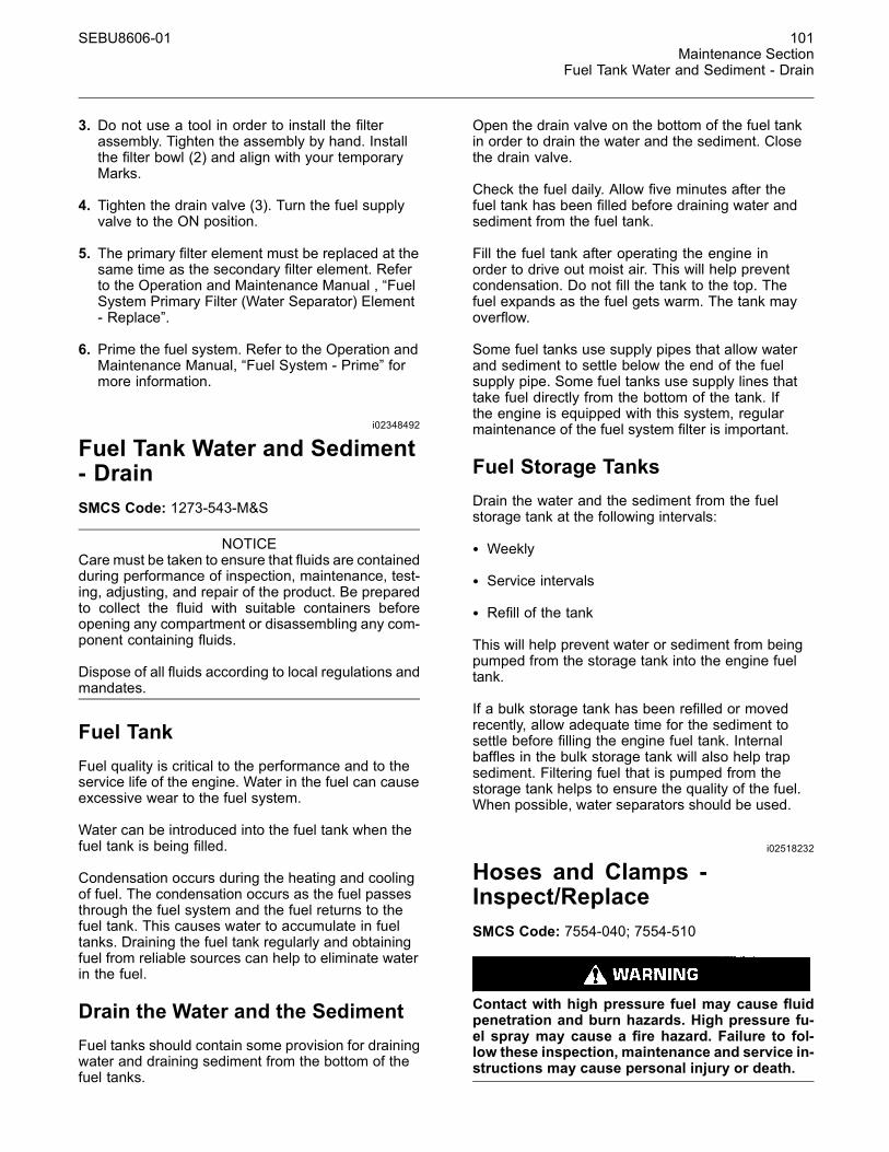
SEBU8606-01 101Maintenance Section
Fuel Tank Water and Sediment - Drain
3. Do not use a tool in order to install the filterassembly. Tighten the assembly by hand. Installthe filter bowl (2) and align with your temporaryMarks.
4. Tighten the drain valve (3). Turn the fuel supplyvalve to the ON position.
5. The primary filter element must be replaced at thesame time as the secondary filter element. Referto the Operation and Maintenance Manual , “FuelSystem Primary Filter (Water Separator) Element- Replace”.
6. Prime the fuel system. Refer to the Operation andMaintenance Manual, “Fuel System - Prime” formore information.
i02348492
Fuel Tank Water and Sediment- DrainSMCS Code: 1273-543-M&S
NOTICECare must be taken to ensure that fluids are containedduring performance of inspection, maintenance, test-ing, adjusting, and repair of the product. Be preparedto collect the fluid with suitable containers beforeopening any compartment or disassembling any com-ponent containing fluids.
Dispose of all fluids according to local regulations andmandates.
Fuel TankFuel quality is critical to the performance and to theservice life of the engine. Water in the fuel can causeexcessive wear to the fuel system.
Water can be introduced into the fuel tank when thefuel tank is being filled.
Condensation occurs during the heating and coolingof fuel. The condensation occurs as the fuel passesthrough the fuel system and the fuel returns to thefuel tank. This causes water to accumulate in fueltanks. Draining the fuel tank regularly and obtainingfuel from reliable sources can help to eliminate waterin the fuel.
Drain the Water and the SedimentFuel tanks should contain some provision for drainingwater and draining sediment from the bottom of thefuel tanks.
Open the drain valve on the bottom of the fuel tankin order to drain the water and the sediment. Closethe drain valve.
Check the fuel daily. Allow five minutes after thefuel tank has been filled before draining water andsediment from the fuel tank.
Fill the fuel tank after operating the engine inorder to drive out moist air. This will help preventcondensation. Do not fill the tank to the top. Thefuel expands as the fuel gets warm. The tank mayoverflow.
Some fuel tanks use supply pipes that allow waterand sediment to settle below the end of the fuelsupply pipe. Some fuel tanks use supply lines thattake fuel directly from the bottom of the tank. Ifthe engine is equipped with this system, regularmaintenance of the fuel system filter is important.
Fuel Storage TanksDrain the water and the sediment from the fuelstorage tank at the following intervals:
• Weekly
• Service intervals
• Refill of the tank
This will help prevent water or sediment from beingpumped from the storage tank into the engine fueltank.
If a bulk storage tank has been refilled or movedrecently, allow adequate time for the sediment tosettle before filling the engine fuel tank. Internalbaffles in the bulk storage tank will also help trapsediment. Filtering fuel that is pumped from thestorage tank helps to ensure the quality of the fuel.When possible, water separators should be used.
i02518232
Hoses and Clamps -Inspect/ReplaceSMCS Code: 7554-040; 7554-510
Contact with high pressure fuel may cause fluidpenetration and burn hazards. High pressure fu-el spray may cause a fire hazard. Failure to fol-low these inspection, maintenance and service in-structions may cause personal injury or death.
102 SEBU8606-01Maintenance SectionOverhaul Considerations
If you inspect the engine in operation, always usethe proper inspection procedure in order to avoida fluid penetration hazard. Refer to Operation andMaintenance Manual, “General hazard Information”.
Inspect all hoses for leaks that are caused by thefollowing conditions:
• Cracking
• Softness
• Loose clamps
Replace hoses that are cracked or soft. Tighten anyloose clamps.
Check for the following conditions:
• End fittings that are damaged or leaking
• Outer covering that is chafed or cut
• Exposed wire that is used for reinforcement
• Outer covering that is ballooning locally
• Flexible part of the hose that is kinked or crushed
• Armoring that is embedded in the outer covering
A constant torque hose clamp can be used in placeof any standard hose clamp. Ensure that the constanttorque hose clamp is the same size as the standardclamp.
Due to extreme temperature changes, the hose willharden. Hardening of the hoses will cause hoseclamps to loosen. This can result in leaks. A constanttorque hose clamp will help to prevent loose hoseclamps.
Each installation application can be different. Thedifferences depend on the following factors:
• Type of hose
• Type of fitting material
• Anticipated expansion and contraction of the hose
• Anticipated expansion and contraction of thefittings
Replace the Hoses and the ClampsRefer to the OEM information for further informationon removing and replacing fuel hoses (if equipped).
The following text describes a typical methodof replacing coolant hoses. Refer to the OEMinformation for further information on the coolantsystem and the hoses for the coolant system.
Pressurized System: Hot coolant can cause seri-ous burns. To open the cooling system filler cap,stop the engine and wait until the cooling systemcomponents are cool. Loosen the cooling systempressure cap slowly in order to relieve the pres-sure.
1. Stop the engine. Allow the engine to cool.
2. Loosen the cooling system filler cap slowly inorder to relieve any pressure. Remove the coolingsystem filler cap.
Note: Drain the coolant into a suitable, cleancontainer. The coolant can be reused.
3. Drain the coolant from the cooling system to alevel that is below the hose that is being replaced.
4. Remove the hose clamps.
5. Disconnect the old hose.
6. Replace the old hose with a new hose.
7. Install the hose clamps with a torque wrench.
Note: For the correct coolant, see this Operation andMaintenance Manual, “Fluid Recommendations”.
8. Refill the cooling system. Refer to the OEMinformation for further information on refilling thecooling system.
9. Clean the cooling system filler cap. Inspect thecooling system filler cap's seals. Replace thecooling system filler cap if the seals are damaged.Install the cooling system filler cap.
10.Start the engine. Inspect the cooling system forleaks.
i04224312
Overhaul ConsiderationsSMCS Code: 7595-043
Reduced hours of operation at full load will result in alower average power demand. A decreased averagepower demand should increase both the engineservice life and the overhaul interval.

SEBU8606-01 103Maintenance Section
Overhaul Considerations
The need for an overhaul is indicated by increasedfuel consumption, increased oil consumption,excessive engine blowby, and reduced power. Arctictemperatures, extreme high temperatures, corrosiveenvironments, or extreme dusty conditions contributeto premature wear and the need for an overhaul.
The following factors are important when a decisionis being made on the proper time for an engineoverhaul:
• The need for preventive maintenance
• The quality of the fuel that is being used
• The operating conditions
• The results of the S·O·S analysis
Oil Consumption as an OverhaulIndicatorOil consumption, fuel consumption, and maintenanceinformation can be used to estimate the totaloperating cost for your Caterpillar engine. Oilconsumption can also be used to estimate therequired capacity of a makeup oil tank that is suitablefor the maintenance intervals.
Oil consumption is in proportion to the percentageof the rated engine load. As the percentage of theengine load is increased, the amount of oil that isconsumed per hour also increases.
The oil consumption rate (brake-specific oilconsumption) is measured in grams per kW/h (lb perbhp). The brake-specific oil consumption (BSOC)depends on the engine load. Consult your Caterpillardealer for assistance in determining the typical oilconsumption rate for your engine.
When an engines oil consumption has risen to threetimes the original oil consumption rate due to normalwear, an engine overhaul should be scheduled.There may be a corresponding increase in blowbyand a slight increase in fuel consumption.
Overhaul Options
Before Failure Overhaul
A planned overhaul before failure may be the bestvalue for the following reasons:
• Costly unplanned downtime can be avoided.
• Many original parts can be reused according to thestandards for reusable parts.
• The engines service life can be extended withoutthe risk of a major catastrophe due to enginefailure.
• The best cost/value relationship per hour ofextended life can be attained.
After Failure Overhaul
If a major engine failure occurs and the enginemust be removed, many options are available. Anoverhaul should be performed if the engine block orthe crankshaft needs to be repaired.
If the engine block is repairable and/or the crankshaftis repairable, the overhaul cost will be less than thecost of a new engine with a similar exchange core.
This lower cost can be attributed to three aspects:
• Specially designed Caterpillar engine features
• Caterpillar dealer exchange components
• Caterpillar Inc. remanufactured exchangecomponents
Overhaul RecommendationTo minimize downtime, Caterpillar Inc. recommends ascheduled engine overhaul by your Caterpillar dealerbefore the engine fails. This process will provide youwith the best cost/value relationship.
Note: Overhaul programs vary according to theengine application and according to the dealer thatperforms the overhaul. Consult your Caterpillardealer for specific information about the availableoverhaul programs and about overhaul services forextending the engine life.
Aftertreatment
The aftertreatment system can be expected tofunction properly for the useful life of the engine(emissions durability period), as defined byregulation, subject to prescribed maintenancerequirements being followed.
Rebuild or Exchange
If an overhaul is performed without overhaul servicefrom your Caterpillar dealer, be aware of the followingmaintenance recommendations.
104 SEBU8606-01Maintenance SectionOverhaul Considerations
Cylinder Head Assembly, Oil Pump, and FuelTransfer Pump
These components should be inspected according tothe instructions that are found in various Caterpillarreusability publications. The Special Publication,SEBF8029 lists the reusability publications that areneeded for inspecting the engine parts.
If the parts comply with the established inspectionspecifications that are expressed in the reusableparts guideline, the parts should be reused.
Parts that are not within the established inspectionspecifications should be dealt with in one of thefollowing manners:
• Salvaging
• Repairing
• Replacing
Using out-of-spec parts can result in the followingproblems:
• Unscheduled downtime
• Costly repairs
• Damage to other engine parts
• Reduced engine efficiency
• Increased fuel consumption
Reduced engine efficiency and increased fuelconsumption translates into higher operating costs.Therefore, Caterpillar Inc. recommends repairingout-of-spec parts or replacing out-of-spec parts.
Inspection and/or Replacement
Crankshaft Bearings Crankshaft Seals andPistons
The following components may not last until thesecond overhaul.
• Thrust bearings
• Main bearings
• Rod bearings
• Crankshaft seals
• Piston assembly
Caterpillar Inc. recommends the installation of newparts at each overhaul period.
Inspect these parts while the engine is disassembledfor an overhaul.
Inspect the crankshaft for any of the followingconditions:
• Deflection
• Damage to the journals
• Bearing material that has seized to the journals
Check the journal taper and the profile of thecrankshaft journals. If the wear patterns on the rodbearing or the main bearing show a problem, thecrankshaft will need to be measured with specialistequipment.
Inspect the camshaft for damage to the journals andto the lobes.
Note: If the camshaft is removed for any reason, usethe magnetic particle inspection process to check forcracks in the camshaft.
Inspect the following components for signs of wear orfor signs of scuffing:
• Camshaft bearings
• Lifters
Caterpillar Inc. recommends replacing the crankshaftvibration damper.
Oil Cooler Core
During an overhaul, Caterpillar Inc. recommends theremoval of the oil cooler core. Clean the oil coolercore. Then, pressure test the oil cooler core.
NOTICEDo not use caustic cleaners to clean the core.
Caustic cleaners can attack the internal metals of thecore and cause leakage.
Note: Use this cleaning procedure to clean the oilcooler core.
1. Remove the oil cooler core.
2. Remove any debris from the oil cooler core. Toremove debris from the oil cooler core, turn the oilcooler core onto one end.
3. Flush the oil cooler core internally with cleaner inorder to loosen foreign substances. This flushingwill also help to remove oil from the oil cooler core.
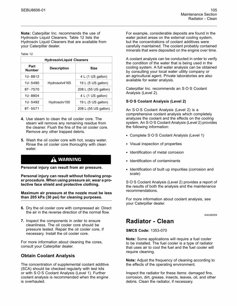
SEBU8606-01 105Maintenance Section
Radiator - Clean
Note: Caterpillar Inc. recommends the use ofHydrosolv Liquid Cleaners. Table 12 lists theHydrosolv Liquid Cleaners that are available fromyour Caterpillar dealer.
Table 12
HydrosolvLiquid Cleaners
PartNumber Description Size
1U-8812 4 L (1 US gallon)
1U-5490 19 L (5 US gallon)
8T-7570
Hydrosolv4165
208 L (55 US gallon)
1U-8804 4 L (1 US gallon)
1U-5492 19 L (5 US gallon)
8T-5571
Hydrosolv100
208 L (55 US gallon)
4. Use steam to clean the oil cooler core. Thesteam will remove any remaining residue fromthe cleaner. Flush the fins of the oil cooler core.Remove any other trapped debris.
5. Wash the oil cooler core with hot, soapy water.Rinse the oil cooler core thoroughly with cleanwater.
Personal injury can result from air pressure.
Personal injury can result without following prop-er procedure.When using pressure air, wear a pro-tective face shield and protective clothing.
Maximum air pressure at the nozzle must be lessthan 205 kPa (30 psi) for cleaning purposes.
6. Dry the oil cooler core with compressed air. Directthe air in the reverse direction of the normal flow.
7. Inspect the components in order to ensurecleanliness. The oil cooler core should bepressure tested. Repair the oil cooler core, ifnecessary. Install the oil cooler core.
For more information about cleaning the cores,consult your Caterpillar dealer.
Obtain Coolant Analysis
The concentration of supplemental coolant additive(SCA) should be checked regularly with test kitsor with S·O·S Coolant Analysis (Level 1). Furthercoolant analysis is recommended when the engineis overhauled.
For example, considerable deposits are found in thewater jacket areas on the external cooling system,but the concentrations of coolant additives werecarefully maintained. The coolant probably containedminerals that were deposited on the engine over time.
A coolant analysis can be conducted in order to verifythe condition of the water that is being used in thecooling system. A full water analysis can be obtainedby consulting your local water utility company oran agricultural agent. Private laboratories are alsoavailable for water analysis.
Caterpillar Inc. recommends an S·O·S CoolantAnalysis (Level 2).
S·O·S Coolant Analysis (Level 2)
An S·O·S Coolant Analysis (Level 2) is acomprehensive coolant analysis which completelyanalyzes the coolant and the effects on the coolingsystem. An S·O·S Coolant Analysis (Level 2) providesthe following information:
• Complete S·O·S Coolant Analysis (Level 1)
• Visual inspection of properties
• Identification of metal corrosion
• Identification of contaminants
• Identification of built up impurities (corrosion andscale)
S·O·S Coolant Analysis (Level 2) provides a report ofthe results of both the analysis and the maintenancerecommendations.
For more information about coolant analysis, seeyour Caterpillar dealer.
i04248509
Radiator - CleanSMCS Code: 1353-070
Note: Some applications will require a fuel coolerto be installed. The fuel cooler is a type of radiatorthat uses air to cool the fuel and the fuel cooler willrequire cleaning.
Note: Adjust the frequency of cleaning according tothe effects of the operating environment.
Inspect the radiator for these items: damaged fins,corrosion, dirt, grease, insects, leaves, oil, and otherdebris. Clean the radiator, if necessary.
106 SEBU8606-01Maintenance SectionRadiator Pressure Cap - Clean/Replace
Personal injury can result from air pressure.
Personal injury can result without following prop-er procedure.When using pressure air, wear a pro-tective face shield and protective clothing.
The maximum air pressure for cleaning purposesmust be reduced to 205 kPa (30 psi) when the airnozzle is deadheaded.
Pressurized air is the preferred method for removingloose debris. Direct the air in the opposite directionof the air flow. Hold the nozzle approximately 6 mm(0.25 inch) away from the fins. Slowly move the airnozzle in a direction that is parallel with the tubes.This movement will remove debris that is betweenthe tubes.
Pressurized water may also be used for cleaning.The maximum water pressure for cleaning purposesmust be less than 275 kPa (40 psi). Use pressurizedwater in order to soften mud. Clean the core fromboth sides.
Use a degreaser and steam for removal of oil andgrease. Clean both sides of the core. Wash the corewith detergent and hot water. Thoroughly rinse thecore with clean water.
After cleaning, start the engine and accelerate theengine to high idle rpm. This procedure will help inthe removal of debris and drying of the core. Stop theengine. Use a light bulb behind the core in order toinspect the core for cleanliness. Repeat the cleaning,if necessary.
Inspect the fins for damage. Bent fins may be openedwith a “comb”. Inspect these items for good condition:welds, mounting brackets, air lines, connections,clamps, and seals. Make repairs, if necessary.
i03639888
Radiator Pressure Cap -Clean/ReplaceSMCS Code: 1353-Z2
Pressurized System: Hot coolant can cause seri-ous burns. To open the cooling system filler cap,stop the engine and wait until the cooling systemcomponents are cool. Loosen the cooling systempressure cap slowly in order to relieve the pres-sure.
NOTICEWhen any servicing or repair of the engine coolingsystem is performed the proceduremust be performedwith the engine on level ground. This will allow you toaccurately check the coolant level. This will also helpin avoiding the risk of introducing an air lock into thecoolant system.
1. Stop the engine and allow the engine to cool.Loosen the cooling system filler cap slowly inorder to relieve any pressure. Remove the radiatorpressure cap.
2. Check coolant level. Refer to Operation andMaintenance Manual, “Cooling System CoolantLevel - Check”.
3. Install new radiator pressure cap.
i00151038
Severe Service Application -CheckSMCS Code: 1000-535
Severe service is an application of an engine thatexceeds current published standards for that engine.Caterpillar maintains standards for the followingengine parameters:
• Performance (power range, speed range, and fuelconsumption)
• Fuel quality
• Altitude range
• Maintenance intervals
• Oil selection and maintenance
• Coolant selection and maintenance
• Environmental qualities
• Installation
Refer to the standards for the engine or consult withyour Caterpillar dealer in order to determine if theengine is operating within the defined parameters.
Severe service operation can accelerate componentwear. Engines that operate under severe conditionsmay need more frequent maintenance intervals inorder to ensure maximum reliability and retention offull service life.
SEBU8606-01 107Maintenance Section
Starting Motor - Inspect
Due to individual applications, it is not possible toidentify all of the factors which can contribute tosevere service operation. Consult your Caterpillardealer for the unique maintenance that is necessaryfor the engine.
The operating environment, improper operatingprocedures and improper maintenance procedurescan be factors which contribute to severe serviceconditions.
Environmental FactorsAmbient temperatures – The engine may beexposed to extended operation in extremelycold environments or hot environments. Valvecomponents can be damaged by carbon buildup ifthe engine is frequently started and stopped in verycold temperatures. Extremely hot inlet air reducesengine performance.
Air Quality – The engine may be exposed toextended operation in an environment that is dirtyor dusty, unless the equipment is cleaned regularly.Mud, dirt and dust can encase components.Maintenance can be very difficult. The buildup cancontain corrosive chemicals.
Buildup – Compounds, elements, corrosivechemicals and salt can damage some components.
Altitude – Problems can arise when the engine isoperated at altitudes that are higher than the intendedsettings for that application. Necessary adjustmentsshould be made.
Improper Operating Procedures• Extended operation at low idle
• Frequent hot shutdowns
• Operating at excessive loads
• Operating at excessive speeds
• Operating outside the intended application
Improper Maintenance Procedures• Extending the maintenance intervals
• Failure to use recommended fuel, lubricants andcoolant/antifreeze
i02348493
Starting Motor - InspectSMCS Code: 1451-040; 1453-040
Caterpillar recommends a scheduled inspection ofthe starting motor. If the starting motor fails, theengine may not start in an emergency situation.
Check the starting motor for correct operation. Checkthe electrical connections and clean the electricalconnections. Refer to the Systems Operation, Testingand Adjusting Manual, “Electric Starting System -Test” for more information on the checking procedureand for specifications or consult your Caterpillardealer for assistance.
i04293330
Turbocharger - InspectSMCS Code: 1052-040; 1052
Hot engine components can cause injury fromburns. Before performing maintenance on theengine, allow the engine and the components tocool.
NOTICETurbocharger bearing failures can cause large quanti-ties of oil to enter the air intake and exhaust systems.Loss of engine lubricant can result in serious enginedamage.
Minor leakage of oil into a turbocharger under extend-ed low idle operation should not cause problems aslong as a turbocharger bearing failure has not oc-cured.
When a turbocharger bearing failure is accompaniedby a significant engine performance loss (exhaustsmoke or engine rpm up at no load), do not continueengine operation until the turbocharger is renewed.
A visual inspection of the turbocharger orturbochargers can minimize unscheduled downtime.A visual inspection of the turbocharger orturbochargers can also reduce the chance forpotential damage to other engine parts. Do notinspect the engine with the engine in operation.

108 SEBU8606-01Maintenance SectionTurbocharger - Inspect
Single Turbocharger
g02136079Illustration 75Typical example
1. Ensure that the turbocharger is clean and free fromdirt before removing components for inspection.
2. Remove the pipe from the turbocharger exhaustoutlet and remove the air intake pipe (1). Visuallyinspect the piping for the presence of oil. Cleanthe interior of the pipes in order to prevent dirtfrom entering during reassembly.
3. Check for obvious heat discoloration of theturbocharger. Check for any loose bolts or anymissing bolts. Check for damage to the oil supplyline and the oil drain line. Check for cracks inthe housing of the turbocharger. Ensure that thecompressor wheel can rotate freely.
4. Check for the presence of oil. If oil is leaking fromthe back side of the compressor wheel, there is apossibility of a failed turbocharger oil seal.
The presence of oil may be the result of extendedengine operation at low idle. The presence of oilmay also be the result of a restriction of the linefor the intake air (clogged air filters), which causesthe turbocharger to slobber.
5. Install the air intake pipe and the exhaust outletpipe to the turbocharger housing. Ensure that allclamps are installed correctly and that all clampsare tightened securely. For more information, referto Systems Operation, Testing, and Adjusting,“Turbocharger - Inspect”.
Engine Install with High Pressureand Low Pressure Turbochargers
g02136113Illustration 76
Typical example
The engine is equipped with a high-pressureturbocharger (1) and a low-pressure turbocharger (3).A regular visual inspection of both turbochargers isrecommended. If the turbocharger fails during engineoperation, damage to the turbocharger compressorwheel and/or to the engine may occur. Damage tothe turbocharger compressor wheel can damage thepistons, the valves, and the cylinder head.
Inspecting
NOTICEThe compressor housing for the turbocharger mustnot be removed from the turbocharger for inspectionor removed for the cleaning of the compressor.
1. Ensure that the turbochargers are clean andfree from dirt before removing components forinspection.
2. Remove the pipe from the high-pressureturbocharger exhaust outlet and remove the airintake pipe to the turbocharger. Visually inspectthe piping for the presence of oil. Clean the interiorof the pipes in order to prevent dirt from enteringduring reassembly.
3. Remove elbow (2) and check for the presence ofengine oil.
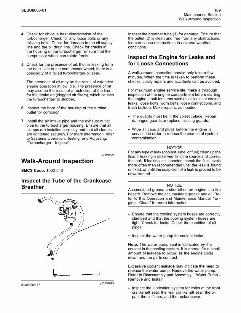
SEBU8606-01 109Maintenance Section
Walk-Around Inspection
4. Check for obvious heat discoloration of theturbocharger. Check for any loose bolts or anymissing bolts. Check for damage to the oil supplyline and the oil drain line. Check for cracks inthe housing of the turbocharger. Ensure that thecompressor wheel can rotate freely.
5. Check for the presence of oil. If oil is leaking fromthe back side of the compressor wheel, there is apossibility of a failed turbocharger oil seal.
The presence of oil may be the result of extendedengine operation at low idle. The presence of oilmay also be the result of a restriction of the linefor the intake air (clogged air filters), which causesthe turbocharger to slobber.
6. Inspect the bore of the housing of the turbineoutlet for corrosion.
7. Install the air intake pipe and the exhaust outletpipe to the turbocharger housing. Ensure that allclamps are installed correctly and that all clampsare tightened securely. For more information, referto Systems Operation, Testing, and Adjusting,“Turbocharger - Inspect”.
i03893509
Walk-Around InspectionSMCS Code: 1000-040
Inspect the Tube of the CrankcaseBreather
g02137093Illustration 77
Inspect the breather tube (1) for damage. Ensure thatthe outlet (2) is clean and free from any obstructions.Ice can cause obstructions in adverse weatherconditions.
Inspect the Engine for Leaks andfor Loose ConnectionsA walk-around inspection should only take a fewminutes. When the time is taken to perform thesechecks, costly repairs and accidents can be avoided.
For maximum engine service life, make a thoroughinspection of the engine compartment before startingthe engine. Look for items such as oil leaks or coolantleaks, loose bolts, worn belts, loose connections, andtrash buildup. Make repairs, as needed:
• The guards must be in the correct place. Repairdamaged guards or replace missing guards.
• Wipe all caps and plugs before the engine isserviced in order to reduce the chance of systemcontamination.
NOTICEFor any type of leak (coolant, lube, or fuel) clean up thefluid. If leaking is observed, find the source and correctthe leak. If leaking is suspected, check the fluid levelsmore often than recommended until the leak is foundor fixed, or until the suspicion of a leak is proved to beunwarranted.
NOTICEAccumulated grease and/or oil on an engine is a firehazard. Remove the accumulated grease and oil. Re-fer to this Operation and Maintenance Manual, “En-gine - Clean” for more information.
• Ensure that the cooling system hoses are correctlyclamped and that the cooling system hoses aretight. Check for leaks. Check the condition of allpipes.
• Inspect the water pump for coolant leaks.
Note: The water pump seal is lubricated by thecoolant in the cooling system. It is normal for a smallamount of leakage to occur, as the engine coolsdown and the parts contract.
Excessive coolant leakage may indicate the need toreplace the water pump. Remove the water pump.Refer to Disassembly and Assembly , “Water Pump -Remove and Install”.
• Inspect the lubrication system for leaks at the frontcrankshaft seal, the rear crankshaft seal, the oilpan, the oil filters, and the rocker cover.
110 SEBU8606-01Maintenance SectionWater Pump - Inspect
• Inspect the piping for the air intake system and theelbows for cracks and for loose clamps. Ensurethat hoses and tubes are not contacting otherhoses, tubes, wiring harnesses.
• Ensure that the areas around the rotating parts areclear.
• Inspect the alternator belts and any accessorydrive belts for cracks, breaks, or other damage.
• Inspect the wiring harness for damage.
Belts for multiple groove pulleys must be replaced asmatched sets. If only one belt is replaced, the belt willcarry more load than the belts that are not replaced.The older belts are stretched. The additional load onthe new belt could cause the belt to break.
High Pressure Fuel Lines
Contact with high pressure fuel may cause fluidpenetration and burn hazards. High pressure fu-el spray may cause a fire hazard. Failure to fol-low these inspection, maintenance and service in-structions may cause personal injury or death.
After the engine has stopped, wait 10 minutes inorder to allow the fuel pressure to be purged from thehigh-pressure fuel lines before any service or repair isperformed. If necessary, perform minor adjustments.Repair any leaks from the low-pressure fuel systemand from the cooling, lubrication, or air systems.Replace any high-pressure fuel line that has leaked.Refer to Disassembly and Assembly Manual, “FuelInjection Lines - Install”.
If you inspect the engine in operation, always usethe proper inspection procedure in order to avoida fluid penetration hazard. Refer to Operation andMaintenance Manual, “General hazard Information”.
Visually inspect the high-pressure fuel lines fordamage or signs of fuel leakage. Replace anydamaged high-pressure fuel lines or high-pressurefuel lines that have leaked.
Ensure that all clips on the high-pressure fuel linesare in place and that the clips are not loose.
• Inspect the rest of the fuel system for leaks. Lookfor loose fuel line clamps.
• Drain the water and the sediment from the fueltank on a daily basis in order to ensure that onlyclean fuel enters the fuel system.
• Inspect the wiring and the wiring harnesses forloose connections and for worn wires or frayedwires. Check for any loose tie-wraps or missingtie-wraps.
• Inspect the ground strap for a good connection andfor good condition.
• Disconnect any battery chargers that are notprotected against the current drain of the startingmotor. Check the condition and the electrolyte levelof the batteries, unless the engine is equipped witha maintenance free battery.
• Check the condition of the gauges. Replace anygauges that are cracked. Replace any gauge thatcannot be calibrated.
i03570653
Water Pump - InspectSMCS Code: 1361-040; 1361
A failed water pump may cause severe engineoverheating problems that could result in the followingconditions:
• Cracks in the cylinder head
• A piston seizure
• Other potential damage to the engine
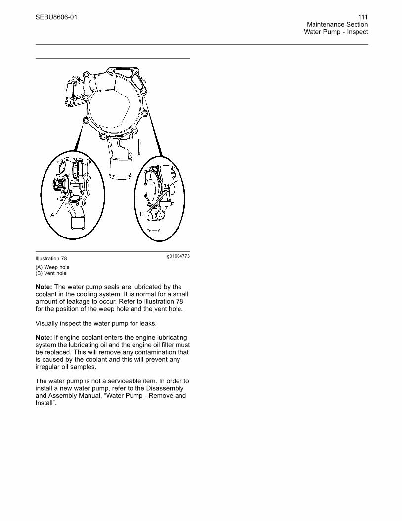
SEBU8606-01 111Maintenance SectionWater Pump - Inspect
g01904773Illustration 78
(A) Weep hole(B) Vent hole
Note: The water pump seals are lubricated by thecoolant in the cooling system. It is normal for a smallamount of leakage to occur. Refer to illustration 78for the position of the weep hole and the vent hole.
Visually inspect the water pump for leaks.
Note: If engine coolant enters the engine lubricatingsystem the lubricating oil and the engine oil filter mustbe replaced. This will remove any contamination thatis caused by the coolant and this will prevent anyirregular oil samples.
The water pump is not a serviceable item. In order toinstall a new water pump, refer to the Disassemblyand Assembly Manual, “Water Pump - Remove andInstall”.
112 SEBU8606-01Warranty SectionWarranty Information
Warranty Section
Warranty Informationi04395613
Emissions WarrantyInformationSMCS Code: 1000
This engine may be certified to comply with exhaustemission standards and gaseous emission standardsthat are prescribed by law at the time of manufacture,and this engine may be covered by an EmissionsWarranty. A detailed explanation of the EmissionsWarranty that is applicable to emissions certifiedengines is found in Supplement, SEBU6981, “FederalEmissions Control Warranty Information”. Consultyour authorized Caterpillar dealer to determine if yourengine is emissions certified and if your engine issubject to an Emissions Warranty.
Engine Protection Plans
Extended Warranties and ServiceContracts
A wide variety of protection plans are available forCaterpillar Engines. Consult your Caterpillar dealerfor detailed information on the specific programs andcoverages that are available.
Consult your Caterpillar dealer for information on aplan that is tailored in order to fit your requirements.

SEBU8606-01 113Reference Information Section
Engine Ratings
Reference InformationSection
Engine Ratingsi03900090
Engine Rating ConditionsSMCS Code: 1000
It is important to know the use of the engine sothat the rating will match the operating profile. Theproper rating selection is also important so that thecustomers perception of price and value is realized.
In selecting a rating for a specific application, themost important consideration is the time that is spentat full throttle. The rating definitions identify thepercent of time at full throttle. The definitions alsoidentify the corresponding times below rated rpm.
Note: For an exact determination of the appropriaterating, follow the OEM specifications or consult yourCaterpillar dealer.
There are five ratings from A to E. The rating for theC4.4 industrial engine is C.
C – Intermittent service with maximum power and/orspeed that are cyclic. The engine at full load shouldnot exceed 50 percent of the duty cycle.
NOTICEOperating engines above the rating definitions can re-sult in shorter service life before overhaul.
i03579033
Engine Rating DefinitionsSMCS Code: 1000
All engine ratings are in compliance with the followingstandard ambient air conditions of “SAE J1349”:
• 100 kPa (29.3 Inches Hg)
• 30 percent relative humidity
• A temperature of 25 °C (77 °F)
Ratings relate to the standard condition of“ISO14396:2002”.
The engine ratings are based on the following fuelspecifications:
• The Low Heat Value (LHV) of the fuel at 29 °C(84.2 °F) at 42780 kJ/kg (18390 Btu/lb)
• Gravity (API) of 35 degrees at 15 °C (60 °F)
• Specific gravity of .849 at 15 °C (60 °F)
The engine ratings are gross output ratings.
Gross Output Ratings – The total output capabilityof the engine that is equipped with standardaccessories.
Standard accessories include the followingcomponents:
• Oil pumps
• Fuel pumps
• Water pumps
Subtract the power that is required to drive auxiliarycomponents from the gross output. This will producethe net power that is available for the external load(flywheel).
114 SEBU8606-01Reference Information SectionCustomer Service
Customer Servicei03996951
Customer AssistanceSMCS Code: 1000
USA and CanadaWhen a problem arises concerning the operation orthe service of an engine, the problem will normally bemanaged by the dealer in your area.
Outside of the USA and of CanadaIf a problem arises outside the USA and outsideCanada, and if the problem cannot be resolved at thedealer level, consult the appropriate Caterpillar office.
Latin America, Mexico, CarribeanCaterpillar Americas Co.701 Waterford Way, Suite 200Miami, FL 33126-4670USAPhone: 305-476-6800Fax: 305-476-6801
Europe, Africa, and Middle EastCaterpillar Overseas S.A.76 Route de FrontenexP.O. Box 6000CH-1211 Geneva 6SwitzerlandPhone: 22-849-4444Fax: 22-849-4544
Far EastCaterpillar Asia Pte. Ltd.7 Tractor RoadJurong, Singapore 627968Republic of SingaporePhone: 65-662-8333Fax: 65-662-8302
ChinaCaterpillar China Ltd.37/F., The Lee Gardens33 Hysan AvenueCauseway BayG.P.O. Box 3069Hong KongPhone: 852-2848-0333Fax: 852-2848-0440
JapanShin Caterpillar Mitsubishi Ltd.SBS Tower10-1, Yoga 4-ChomeSetagaya-Ku, Tokyo 158-8530JapanPhone: 81-3-5717-1150Fax: 81-3-5717-1177
JapanCaterpillar Power Systems, Inc.SBS Tower (14th floor)4-10-1, YogaSetagaya-Ku, Tokyo 158-0097Phone: 81-3-5797-4300Fax: 81-3-5797-4359
Australia and New ZealandCaterpillar of Australia Ltd.1 Caterpillar DrivePrivate Mail Bag 4Tullamarine, Victoria 3043AustraliaPhone: 03-9953-9333Fax: 03-9335-3366
i03655027
Ordering Replacement PartsSMCS Code: 7567
When replacement parts are required for thisproduct Caterpillar recommends using Caterpillarreplacement parts or parts with equivalent spec-ifications including, but not limited to, physicaldimensions, type, strength and material.
Failure to heed this warning can lead to prema-ture failures, product damage, personal injury ordeath.
Quality Caterpillar replacement parts are availablefrom Caterpillar dealers throughout the world.Caterpillar dealers' parts inventories are up-to-date.The parts stocks include all of the parts that arenormally needed to protect your Caterpillar engineinvestment.
When you order parts, please specify the followinginformation:
• When a Caterpillar engine requires maintenanceand/or repair, provide the dealer with all theinformation that is stamped on the InformationPlate. Refer to this Operation and MaintenanceManual, “Plate Locations and Film Locations”.

SEBU8606-01 115Reference Information Section
Customer Service
• Part number
• Part name
• Quantity
If there is a question concerning the part number,please provide your dealer with a completedescription of the needed item.
Discuss the problem with the dealer. Inform thedealer about the conditions of the problem and thenature of the problem. Inform the dealer about whenthe problem occurs. This will help the dealer introubleshooting the problem and solving the problemfaster.
116 SEBU8606-01Reference Information SectionReference Materials
Reference Materialsi04390416
Reference MaterialSMCS Code: 1000
The following literature can be obtained through anyCaterpillar dealer.
Lubricants• Special Publication, PEHP0002, “Data Sheet -Molybdenum (MPGM) Grease”
• Special Publication, NEHP6015, “Data Sheet -Caterpillar High Speed Bearing Grease”
• Special Publication, SEBD0640, “Oil and YourEngine”
• Operation and Maintenance Manual, SEBU5898,“Cold Weather Recommendations”
• Operation and Maintenance Manual, SEBU6251,“Caterpillar Commercial Diesel Engine FluidsRecommendations”
• Special Publication, PEHP6001, “How To Take AGood Oil Sample”
Coolants• Special Publication, PEHP7057, “Data Sheet -S·O·S Coolant Analysis”
• Special Publication, SEBD0970, “Coolant and YourEngine”
Miscellaneous• Service Manual, REG1139F, “Service ManualContents Microfiche”
• Service Manual, KENR9133, “C4.4 IndustrialEngines”
• Troubleshooting, KENR9111, “C4.4 IndustrialEngines”
• Systems Operation, Testing, and Adjusting,KENR9119, “C4.4 Industrial Engines”
• Specifications, KENR9118, “C4.4 IndustrialEngines.”
• Disassembly and Assembly, KENR9120, “C4.4Industrial Engines”
• Specifications, SENR3130, “Torque Specifications”
• Special Publication, SEBF8029, “Index toGuidelines for Reusable Parts and SalvageOperations”
• Special Instruction, SEHS9031, “StorageProcedure for Caterpillar Products”
• Special Publication, SEBU6251, “CaterpillarCommercial Diesel Engine FluidsRecommendations”
• Special Instruction, SEHS7633, “Battery TestProcedure”
i02780825
Additional Reference MaterialSMCS Code: 1000
The “Society of Automotive Engineers (SAE)Specifications” can be found in your SAE handbook.This publication can also be obtained from thefollowing locations: local technological society, locallibrary, and local college. If necessary, consult SAEat the following address:
SAE International400 Commonwealth DriveWarrendale, PA, USA 15096-0001Telephone: (724) 776-4841
The “American Petroleum Institute Publication No.1509” can be obtained from the following locations:local technological society, local library, and localcollege. If necessary, consult API at the followingaddress:
American Petroleum Institute1220 L St. N.W.Washington, DC, USA 20005Telephone: (202) 682-8000
The International Organization for Standardization(ISO) offers information and customer serviceregarding international standards and standardizingactivities. ISO can also supply information on thefollowing subjects that are not controlled by ISO:national standards, regional standards, regulations,certification, and related activities. Consult themember of ISO in your country.
SEBU8606-01 117Reference Information Section
Reference Materials
International Organization for Standardization(ISO)1, rue de VarembéCase postale 56CH-1211 Genève 20SwitzerlandTelephone: +41 22 749 01 11Facsimile: +41 22 733 34 30E-mail: [email protected] site: http://www.iso.ch
European classifications are established by theCounseil International Des Machines a Combustion(CIMAC) (International Council on CombustionEngines).
CIMAC Central SecretariatLyoner Strasse 1860528 FrankfurtGermanyTelephone: +49 69 6603 1567Facsimile: +49 69 6603 1566
i03989612
Decommissioning andDisposalSMCS Code: 1000
When the product is removed from service, localregulations for the product decommissioning willvary. Disposal of the product will vary with localregulations. Consult the nearest Cat dealer foradditional information.
i00912149
Maintenance RecordsSMCS Code: 1000
Caterpillar Inc. recommends the retention of accuratemaintenance records. Accurate maintenance recordscan be used for the following purposes:
• Determine operating costs.
• Establish maintenance schedules for other enginesthat are operated in the same environment.
• Show compliance with the required maintenancepractices and maintenance intervals.
Maintenance records can be used for a variety ofother business decisions that are related to enginemaintenance.
Maintenance records are a key element of amaintenance program that is well managed. Accuratemaintenance records can help your Caterpillar dealerto fine tune the recommended maintenance intervalsin order to meet the specific operating situation. Thisshould result in a lower engine operating cost.
Records should be kept for the following items:
Fuel Consumption – A record of fuel consumptionis essential in order to determine when the loadsensitive components should be inspected orrepaired. Fuel consumption also determines overhaulintervals.
Service Hours – A record of service hours isessential to determine when the speed sensitivecomponents should be inspected or repaired.
Documents – These items should be easy toobtain, and these items should be kept in the enginehistory file. All of the documents should show thisinformation: date, service hours, fuel consumption,unit number, and engine serial number. The followingtypes of documents should be kept as proof ofmaintenance or repair for warranty:
Keep the following types of documents as proof ofmaintenance for warranty. Also, keep these types ofdocuments as proof of repair for warranty:
• Dealer work orders and itemized bills
• Owner's repair costs
• Owner's receipts
• Maintenance log

118 SEBU8606-01Reference Information SectionReference Materials
i01176304
Maintenance LogSMCS Code: 1000
Table 13
Engine Model Customer Identifier
Serial Number Arrangement Number
ServiceHours
QuantityOf Fuel Service Item Date Authorization
SEBU8606-01 119Index Section
Index
A
Additional Reference Material .............................. 116After Starting Engine ............................................. 54After Stopping Engine............................................ 57Aftercooler Core - Clean/Test (Air-To-AirAftercooler) .......................................................... 73Aftercooler Core - Inspect...................................... 73Alternator - Inspect ................................................ 73Alternator and Fan Belts - Replace ....................... 73
B
Battery - Replace................................................... 74Battery Electrolyte Level - Check .......................... 74Battery or Battery Cable - Disconnect ................... 75Before Starting Engine .................................... 16, 52Belt - Inspect.......................................................... 75Belt Tensioner - Inspect ......................................... 76Burn Prevention...................................................... 11Batteries............................................................. 12Coolant............................................................... 12Induction System ............................................... 12Oils..................................................................... 12
C
Cold Weather Operation........................................ 59Hints for Cold Weather Operation...................... 59Idling the Engine ................................................ 60Recommendations for Coolant Warm Up .......... 60Recommendations for the Coolant .................... 60Viscosity of the Engine Lubrication Oil............... 59
Cold Weather Starting ........................................... 52Configuration Parameters...................................... 48Customer Specified Parameters ........................ 49System Configuration Parameters ..................... 48
Cooling System Coolant (DEAC) - Change........... 76Cooling Systems with Heavy Deposits orPlugging ........................................................... 77Drain .................................................................. 76Fill ...................................................................... 78Flush .................................................................. 77
Cooling System Coolant (ELC) - Change.............. 78Drain .................................................................. 79Fill ...................................................................... 79Flush .................................................................. 79
Cooling System Coolant Extender (ELC) - Add..... 80Cooling System Coolant Level - Check ................. 81Cooling System Coolant Sample (Level 1) -Obtain .................................................................. 81Cooling System Coolant Sample (Level 2) -Obtain .................................................................. 82
Cooling System Supplemental Coolant Additive(SCA) - Test/Add.................................................. 83Add the SCA, If Necessary ................................ 83S·O·S Coolant Analysis...................................... 83Test for SCA Concentration ............................... 83
Crushing Prevention and Cutting Prevention ........ 14Customer Assistance............................................ 114Outside of the USA and of Canada................... 114USA and Canada.............................................. 114
Customer Service ................................................. 114
D
Decommissioning and Disposal ........................... 117Diagnostic Flash Code Retrieval ........................... 46Diagnostic Lamp.................................................... 46
E
Electrical System................................................... 17Grounding Practices .......................................... 18
Emergency Stopping ............................................. 57Emergency Stop Button ..................................... 57
Emissions Certification Film .................................. 30Emissions Warranty Information........................... 112Engine Protection Plans.................................... 112
Engaging the Driven Equipment............................ 55Engine - Clean....................................................... 84Aftertreatment .................................................... 84
Engine Air Cleaner Element (Dual Element) -Clean/Replace ..................................................... 84Cleaning the Primary Air Cleaner Elements ...... 85Servicing the Air Cleaner Elements ................... 84
Engine Air Cleaner Element (Single Element) -Inspect/Replace................................................... 87Engine Air Cleaner Element (Single Element) -Replace................................................................ 87Engine Air Cleaner Service Indicator - Inspect...... 88Test the Service Indicator................................... 88
Engine Air Precleaner - Check/Clean.................... 89Engine Crankcase Breather Element - Replace.... 89Check the System.............................................. 91
Engine Description ................................................ 26Aftermarket Products and Caterpillar Engines... 28Aftertreatment System ....................................... 27Electronic Engine Features................................ 27Engine Cooling and Lubrication ......................... 27Engine Diagnostics ............................................ 27Engine Service Life ............................................ 28Engine Specifications......................................... 26
Engine Diagnostics................................................ 46Engine Electronics................................................. 18Engine Mounts - Inspect........................................ 91
120 SEBU8606-01Index Section
Engine Oil and Filter - Change .............................. 92Drain the Engine Lubricating Oil ........................ 93Fill the Oil Pan.................................................... 95Replace the Oil Filter ......................................... 93
Engine Oil Level - Check....................................... 91Engine Oil Sample - Obtain ................................... 92Obtain the Sample and the Analysis.................. 92
Engine Operation................................................... 55Reduction of Particulate Emissions ................... 55
Engine Operation with Active Diagnostic Codes ... 48Engine Operation with Intermittent DiagnosticCodes .................................................................. 48Engine Rating Conditions..................................... 113Engine Rating Definitions ..................................... 113Engine Ratings ..................................................... 113Engine Shutoffs and Engine Alarms...................... 44Alarms................................................................ 44Shutoffs.............................................................. 44Testing................................................................ 45
Engine Starting ................................................ 17, 52Engine Stopping .............................................. 17, 57
F
Fan Clearance - Check.......................................... 95Fault Logging......................................................... 47Features and Controls ........................................... 36Fire Prevention and Explosion Prevention ............ 12Ether .................................................................. 14Fire Extinguisher ................................................ 14Lines, Tubes, and Hoses ................................... 14
Foreword ................................................................. 5California Proposition 65 Warning ....................... 5Literature Information........................................... 4Maintenance ........................................................ 4Maintenance Intervals.......................................... 4Operation ............................................................. 4Overhaul .............................................................. 4Safety................................................................... 4
Fuel and the Effect from Cold Weather ................. 61Fuel Conservation Practices.................................. 56Fuel Related Components in Cold Weather .......... 62Fuel Filters ......................................................... 62Fuel Heaters ...................................................... 62Fuel Tanks.......................................................... 62
Fuel System - Prime.............................................. 96Fuel System Primary Filter (Water Separator)Element - Replace ............................................... 97In-line Strainer.................................................... 98Install the Element ............................................. 98Remove the Element ......................................... 97
Fuel System Primary Filter/Water Separator -Drain .................................................................... 99Fuel System Secondary Filter - Replace............... 99Install the Element ........................................... 100Remove the Element ......................................... 99
Fuel Tank Water and Sediment - Drain ............... 101Drain the Water and the Sediment................... 101Fuel Storage Tanks.......................................... 101Fuel Tank ......................................................... 101
G
Gauges and Indicators .......................................... 34Indicator Lamps ................................................. 35Instrument panels and Displays......................... 35
General Hazard Information .................................... 8Asbestos Information .......................................... 11Containing Fluid Spillage ................................... 10Dispose of Waste Properly ................................. 11Fluid Penetration................................................ 10Pressurized Air and Water ................................. 10
H
High Pressure Fuel Lines ...................................... 15Hoses and Clamps - Inspect/Replace ................. 101Replace the Hoses and the Clamps ................ 102
I
Important Safety Information ................................... 2
L
Lifting and Storage ................................................ 31
M
Maintenance Interval Schedule ............................. 72Maintenance Log.................................................. 118Maintenance Recommendations........................... 70Maintenance Records........................................... 117Maintenance Section............................................. 64Model View Illustrations......................................... 20Engine Aftertreatment System........................... 26Engine with a Single Turbocharger.................... 23Series Turbocharger Arrangement .................... 20
Model Views .......................................................... 20Monitoring System................................................. 36Programmable Options and SystemsOperation ......................................................... 36
Monitoring System (Table for the Indicatorlamps) .................................................................. 38Mounting and Dismounting.................................... 15
O
Operation Section.................................................. 31Ordering Replacement Parts ................................ 114Overhaul Considerations..................................... 102Oil Consumption as an Overhaul Indicator ...... 103Overhaul Recommendation ............................. 103
Overspeed............................................................. 45

SEBU8606-01 121Index Section
P
Plate Locations and Film Locations....................... 29Serial Number Plate (1) ..................................... 29
Product Identification Information .......................... 29Product Information Section .................................. 20Product Lifting (Clean Emission Module) .............. 31Product Lifting (Engine) ......................................... 31Industrial Open Power Unit ................................ 32
Product Storage..................................................... 33
R
Radiator - Clean .................................................. 105Radiator Pressure Cap - Clean/Replace ............. 106Radiator Restrictions ............................................. 61Reference Information Section ............................. 113Reference Material ............................................... 116Coolants............................................................ 116Lubricants ......................................................... 116Miscellaneous ................................................... 116
Reference Materials ............................................. 116Reference Numbers .............................................. 29Record for Reference......................................... 29
Refill Capacities..................................................... 64Refill Capacities and Recommendations............... 64Coolant............................................................... 66Engine Oil .......................................................... 64Fuel .................................................................... 66Lubricating Grease............................................. 66S·O·S Coolant Analysis...................................... 67
S
Safety Messages..................................................... 6(1) Universal Warning .......................................... 6(2) Hand (High Pressure)..................................... 7Ether Warning ...................................................... 8
Safety Section ......................................................... 6Self-Diagnostics..................................................... 46Sensors and Electrical Components ..................... 39Sensors and Electrical Components(Aftertreatment).................................................... 39Severe Service Application - Check .................... 106Environmental Factors ..................................... 107Improper Maintenance Procedures.................. 107Improper Operating Procedures ...................... 107
Starting Motor - Inspect ....................................... 107Starting the Engine................................................ 52Starting the Engine ............................................ 52
Starting with Jump Start Cables ............................ 53Stopping the Engine .............................................. 57System Pressure Release..................................... 70Coolant System.................................................. 70Engine Oil .......................................................... 70Fuel System....................................................... 70
T
Table of Contents..................................................... 3Turbocharger - Inspect ........................................ 107Engine Install with High Pressure and LowPressure Turbochargers ................................ 108Inspecting......................................................... 108Single Turbocharger ........................................ 108
W
Walk-Around Inspection ...................................... 109High Pressure Fuel Lines.................................. 110Inspect the Engine for Leaks and for LooseConnections ................................................... 109Inspect the Tube of the Crankcase Breather ... 109
Warranty Information ............................................ 112Warranty Section .................................................. 112Water Pump - Inspect ........................................... 110Welding on Engines with Electronic Controls ........ 70

122 SEBU8606-01Index Section
Product and Dealer InformationNote: For product identification plate locations, see the section “Product Identification Information” in the Operationand Maintenance Manual.
Delivery Date:
Product InformationModel:
Product Identification Number:
Engine Serial Number:
Transmission Serial Number:
Generator Serial Number:
Attachment Serial Numbers:
Attachment Information:
Customer Equipment Number:
Dealer Equipment Number:
Dealer InformationName: Branch:
Address:
Dealer Contact Phone Number Hours
Sales:
Parts:
Service:

©2011 CaterpillarAll Rights Reserved
Cat, Caterpillar, their respective logos, “Caterpillar Yellow” and the Power edgetrade dress, as well as corporate and product identity used herein, are trademarksof Caterpillar and may not be used without permission.