operation and maintenance manual - renewable … and maintenance manual wind and solar energy...
TRANSCRIPT

Operation and Maintenance Manual
Wind and Solar Energy Powered
Water Pumping System
Sitio Buli, Cabra, Lubang Island,
Mindoro Occidental
Date created: 23rd April 2008 Version: 1.0

1
Contact Information
SIBAT:
Office address and contact details: 4th and 5th Floor, 40 Matulungin Street,
Brgy Central, Diliman, Quezon City, 1100
Phone: (632) 926-8971 Telefax: (632) 928-8316
Email: [email protected]
Engineer Andrew Corbyn – Cell Phone: 09164 871 376 Email: [email protected]
Engineer Carlo Fabia – Cell Phone: 09266 449 260
Email: [email protected]
Engineer Matthew Little – Cell Phone: 09159 864 816 Email: [email protected]
Administrative Officer Jove Benosa – Cell Phone: 09208 264 873
Email: [email protected]
LGU:
Municipal Planning and Development Office:
Engineer Alfred Insigne – Cell Phone: 09182 090 006
National Disaster Coordinator Gina – Cell Phone: 09214 224 387
Local Peoples Organisation:
****info required****

Contents Contact Information...............................................................................................1 Contents ...............................................................................................................2 Installed System....................................................................................................4
O&M Logbook ...................................................................................................5 Operation ..............................................................................................................6
In event of typhoon............................................................................................9 Maintenance Overview .......................................................................................10
Daily ................................................................................................................10 Monthly............................................................................................................10 Yearly ..............................................................................................................11
Wind Turbine.......................................................................................................16 Safety ..............................................................................................................20
General safety .............................................................................................20 Wind turbine maintenance safety.................................................................20
Raising and lowering tower .............................................................................20 Safety ..........................................................................................................20
Wind turbine lowering process ........................................................................22 Wind turbine raising process ...........................................................................24 Wind turbine assembly ....................................................................................28 Wind turbine disassembly ...............................................................................33 Maintenance....................................................................................................34 Troubleshooting...............................................................................................37
Solar Panels........................................................................................................40 Safety ..............................................................................................................40 Maintenance....................................................................................................40 Troubleshooting...............................................................................................40
Batteries..............................................................................................................41 Safety ..............................................................................................................41 Maintenance....................................................................................................45 Troubleshooting...............................................................................................46
Controls ..............................................................................................................47 1. Charge controller .....................................................................................48 2. Dump load ...............................................................................................48 3. System voltage ........................................................................................48 4. Solar current ............................................................................................49 5. Solar panel regulator................................................................................49 6. Wind current ............................................................................................50 7. Wind turbine rectifier ................................................................................50 8. Pump current ...........................................................................................50 9. Pump controls..........................................................................................50
Maintenance....................................................................................................51 Troubleshooting...............................................................................................51
Inverter................................................................................................................52 Maintenance....................................................................................................53

Troubleshooting...............................................................................................53 Pump ..................................................................................................................55
Pump raising procedure ..................................................................................55 Maintenance....................................................................................................55 Troubleshooting...............................................................................................56
Tools ...................................................................................................................57 Tools for tower erection...................................................................................57 Tools for wind turbine servicing .......................................................................57 Tools for electrical systems .............................................................................57
Appendices .........................................................................................................58
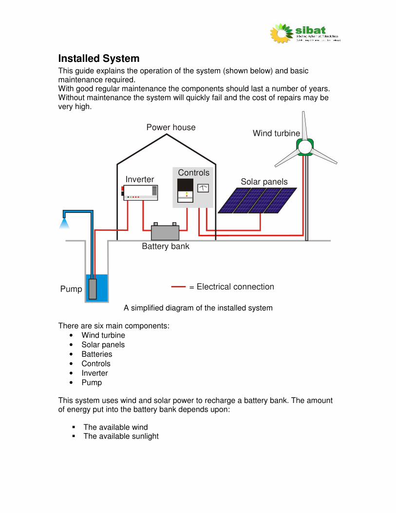
Installed System This guide explains the operation of the system (shown below) and basic maintenance required. With good regular maintenance the components should last a number of years. Without maintenance the system will quickly fail and the cost of repairs may be very high.
= Electrical connection
Power houseWind turbine
Solar panelsControls
Battery bank
Inverter
Pump
A simplified diagram of the installed system
There are six main components:
• Wind turbine
• Solar panels
• Batteries
• Controls
• Inverter
• Pump This system uses wind and solar power to recharge a battery bank. The amount of energy put into the battery bank depends upon:
� The available wind � The available sunlight

More wind or sun on a given day will mean that the battery bank will store more energy. The energy stored in the batteries is used to pump water up from a well. The water is stored in a set of water barrels. An automatic float switch turns off the pump when the barrels are full. The pump is turned ON and OFF in the powerhouse by the system operator. The system operator controls how long the pump can be run by looking at how much energy is in the battery. If there has been a lot of sun or wind then the pump can be run for a longer time. If it has been cloudy or there has been no wind then the pump should be run for a shorter time. The judgement of how long to run the pump must be made by the system operator depending upon the system voltage, the charge regulator indicator lights, the current from the wind turbine and solar panels and the recent weather pattern.
O&M Logbook
Keep a daily record in the Operation & Maintenance (O&M) Logbook of:
• Time
• Date
• Operator’s name
• Battery voltage before running pump
• The length of time the pump is run
• Battery voltage after running pump
• Problems and observations
• Maintenance
• Cost involved
This information will be required by the SIBAT engineers in the event of a problem.
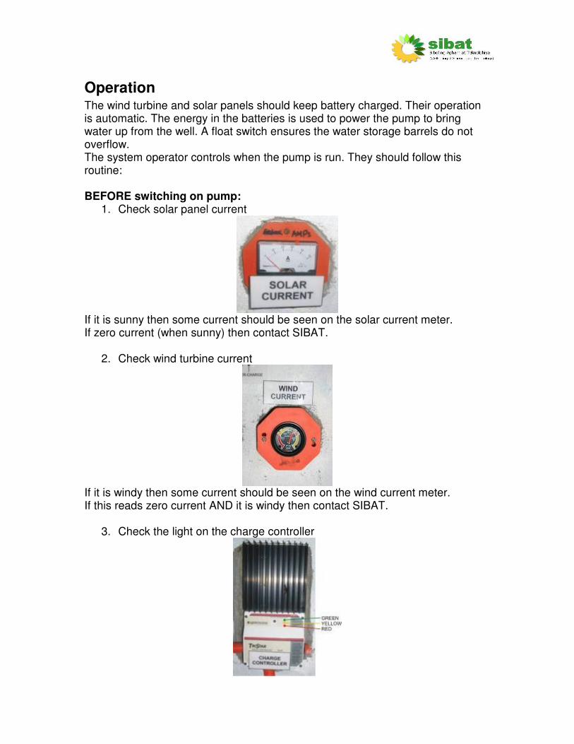
Operation The wind turbine and solar panels should keep battery charged. Their operation is automatic. The energy in the batteries is used to power the pump to bring water up from the well. A float switch ensures the water storage barrels do not overflow. The system operator controls when the pump is run. They should follow this routine: BEFORE switching on pump:
1. Check solar panel current
If it is sunny then some current should be seen on the solar current meter. If zero current (when sunny) then contact SIBAT.
2. Check wind turbine current
If it is windy then some current should be seen on the wind current meter. If this reads zero current AND it is windy then contact SIBAT.
3. Check the light on the charge controller
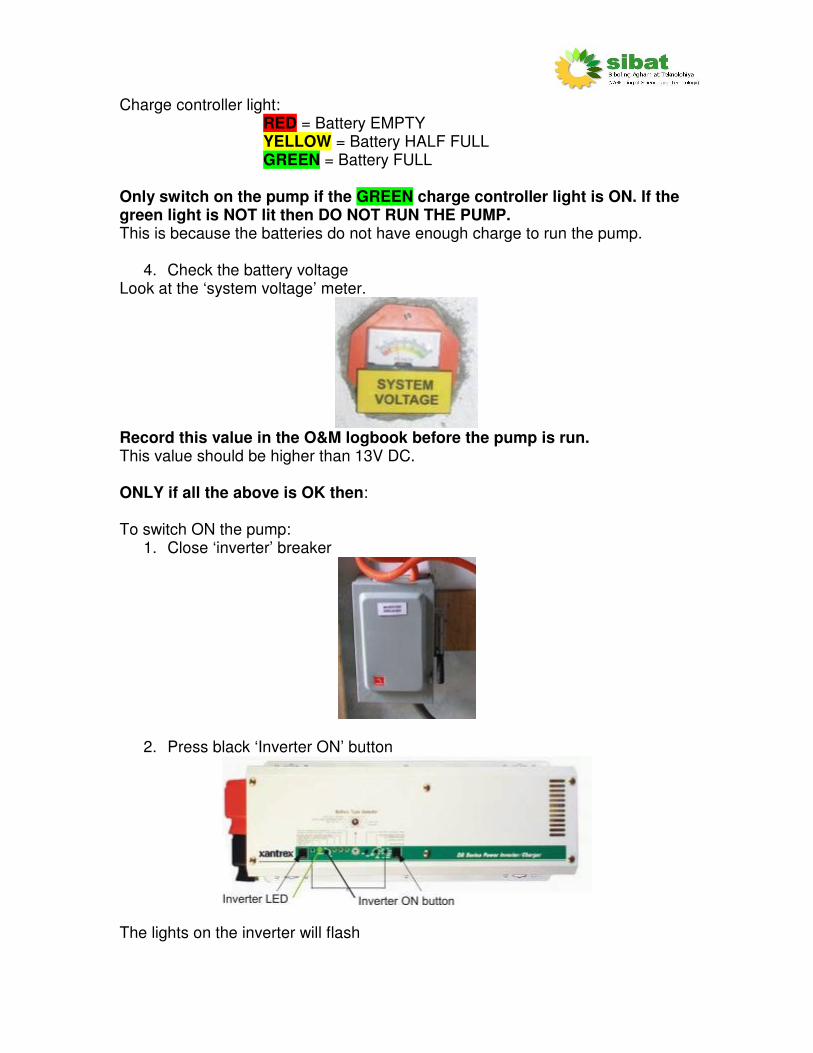
Charge controller light: RED = Battery EMPTY YELLOW = Battery HALF FULL GREEN = Battery FULL
Only switch on the pump if the GREEN charge controller light is ON. If the green light is NOT lit then DO NOT RUN THE PUMP. This is because the batteries do not have enough charge to run the pump.
4. Check the battery voltage Look at the ‘system voltage’ meter.
Record this value in the O&M logbook before the pump is run. This value should be higher than 13V DC. ONLY if all the above is OK then: To switch ON the pump:
1. Close ‘inverter’ breaker
2. Press black ‘Inverter ON’ button
The lights on the inverter will flash
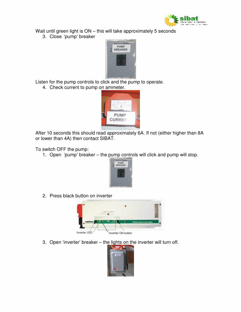
Wait until green light is ON – this will take approximately 5 seconds 3. Close ‘pump’ breaker
Listen for the pump controls to click and the pump to operate.
4. Check current to pump on ammeter.
After 10 seconds this should read approximately 6A. If not (either higher than 8A or lower than 4A) then contact SIBAT. To switch OFF the pump:
1. Open ‘pump’ breaker – the pump controls will click and pump will stop.
2. Press black button on inverter
3. Open ‘inverter’ breaker – the lights on the inverter will turn off.

4. Look at the ‘system voltage’ meter. This value should be recorded in the O&M logbook.
In event of typhoon
A strong typhoon may cause damage to the wind turbine. The Memorandum of Agreement between Buli PO, the LGU and SIBAT dictates that the LGU will give advance warning to the Buli PO in the event of a signal 3 typhoon. Buli PO should lower the wind turbine as soon as possible after receiving the warning to avoid damage to the turbine. The wind turbine can be erected again as soon as the storm has passed.
Maintenance Overview ALL maintenance jobs completed should be recorded in the Operation and Maintenance Logbook.
Daily
• Check and record system voltage: Is this with acceptable range? Should the pump be run?
• Listen to wind turbine: Does it sound OK? Does it sound different to previous days?
• Look at wind turbine and mast: Does anything look damaged?
Monthly
1. Clean batteries:
Warning: there could be battery acid present. Wear acid-resistant gloves and goggles. Wipe the tops with a slightly damp cloth then dry thoroughly.
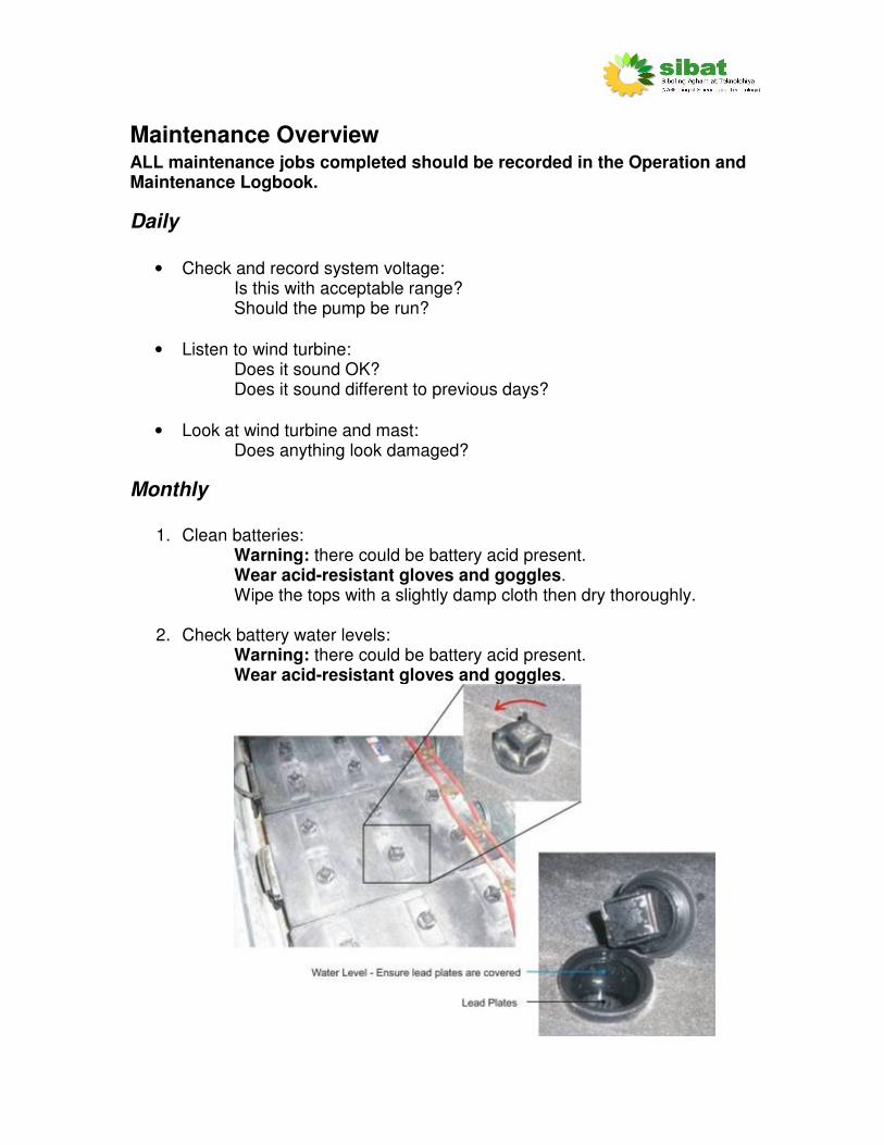
2. Check battery water levels: Warning: there could be battery acid present. Wear acid-resistant gloves and goggles.
Take each battery in turn. Remove the caps from the battery. If any grey metal can be seen, then the levels are too low. The battery should be filled nearly to the top with DISTILLED water. Then replace the lids. Ensure no dirt or debris enters the batteries while the tops are removed.
3. Clean powerhouse: The power house should be kept clean and dry.
Do not use the power house as a storeroom. Always ensure a clear path to the door.
4. Check tools: Ensure all tools are in their correct location. Check they are in good working order.
Tools should be kept clean and dry.
Yearly
1. Clean solar panels:
Use slightly soapy water and a soft cloth. Rinse well with fresh water. Dry thoroughly. Careful when working at heights
2. Full inspection of wind turbine
Lower the wind turbine - follow raise/lower procedure in wind turbine chapter.
a. Cleaning The blades should be cleaned with soapy water to remove any dirt or salt. Inspect the blades for cracks, holes, rust, fatigue or bent sections and make a note in the operation and maintenance log book.
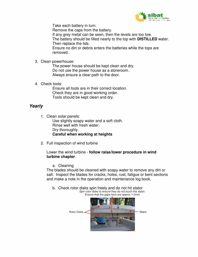
b. Check rotor disks spin freely and do not hit stator Spin rotor disks to ensure they do not touch the stator.
Ensure that the gaps here are approx 1-2mm
Rotor Disks Stator

c. Painting. All painted steel parts on the wind turbine, tower and foundations should be painted periodically to prevent rusting. This includes:
� Chassis and yaw pipe � Tail � Bearing � Guy wire connecting strips � Guy wire foundation posts � Tower base and hinge
If the parts are already rusty, apply rust remover and clean the part, then apply a fresh coat of paint. The wooden tail vane should also be painted periodically. After a few years the tail vane may become weathered and cracked. This can be replaced with wood of an equivalent size, shape and weight.
d. Lubrication The wind turbine chassis rotates around the top of the tower to follow the wind. The point of rotation (where the chassis sits on top of the tower) is called the yaw bearing. This bearing must be kept lubricated to ensure easy rotation of the turbine. To do this, apply grease to the tube at the top of the tower before the chassis is placed onto the tower.
Chassis
Top of tower
Applygreasehere
e. Check bearing Ensure that the bearing rotates freely but without any ‘wobble’. If any noise can be heard from the bearing or it does not rotate correctly then replace the bearing.
Spin rotor disks to check bearing.

f. Cable twist
Two power cables go from the rectifier box, down the tower and to the power house. It is possible that these cables can become twisted due to the rotation of the wind turbine chassis on the tower. When the wind turbine is lowered, check to see if the cables have become too twisted. If they are, then rectify this by disconnecting the positive and negative terminals from the rectifier within the rectifier box. You may need to cut away the sealant on the entry point to the rectifier box. Untwist the cables manually. When untwisted reconnect the terminals ensuring the correct polarity.
Ensure these entry points are sealed
Apply sealant around lid beforesealing the box
2 x DC CablesThese go down
the tower
3 x AC CablesThese go to the stator
Ensure correctpolarity
Re-apply sealant to the cable entry points to the rectifier box and around the lid of the rectifier box. Tightly fasten the lid screws to ensure that the rectifier box is fully sealed. Note: This system does not use a waterproof box. Future systems should.
g. Check tower and turnbuckles Ensure they are all tight and that the tower is straight.

Guy cable
Guy cable clamp
Thimble
Turnbuckle
When everything has been checked, raise the turbine (follow raise/lower
procedure in the ‘wind turbine’ chapter).
3. Pump maintenance The pump is at the end of the water pipe, submerged under the well water level. The pump should require minimal maintenance although it ought to be raised every year for a visual inspection and a thorough clean. The pump is very complicated and contains no user-serviceable parts. DO NOT attempt to open the unit. If no problem can be seen then refer to SIBAT or the pump manufacturer.

Pump raising process (***need to define this – what is best?****)
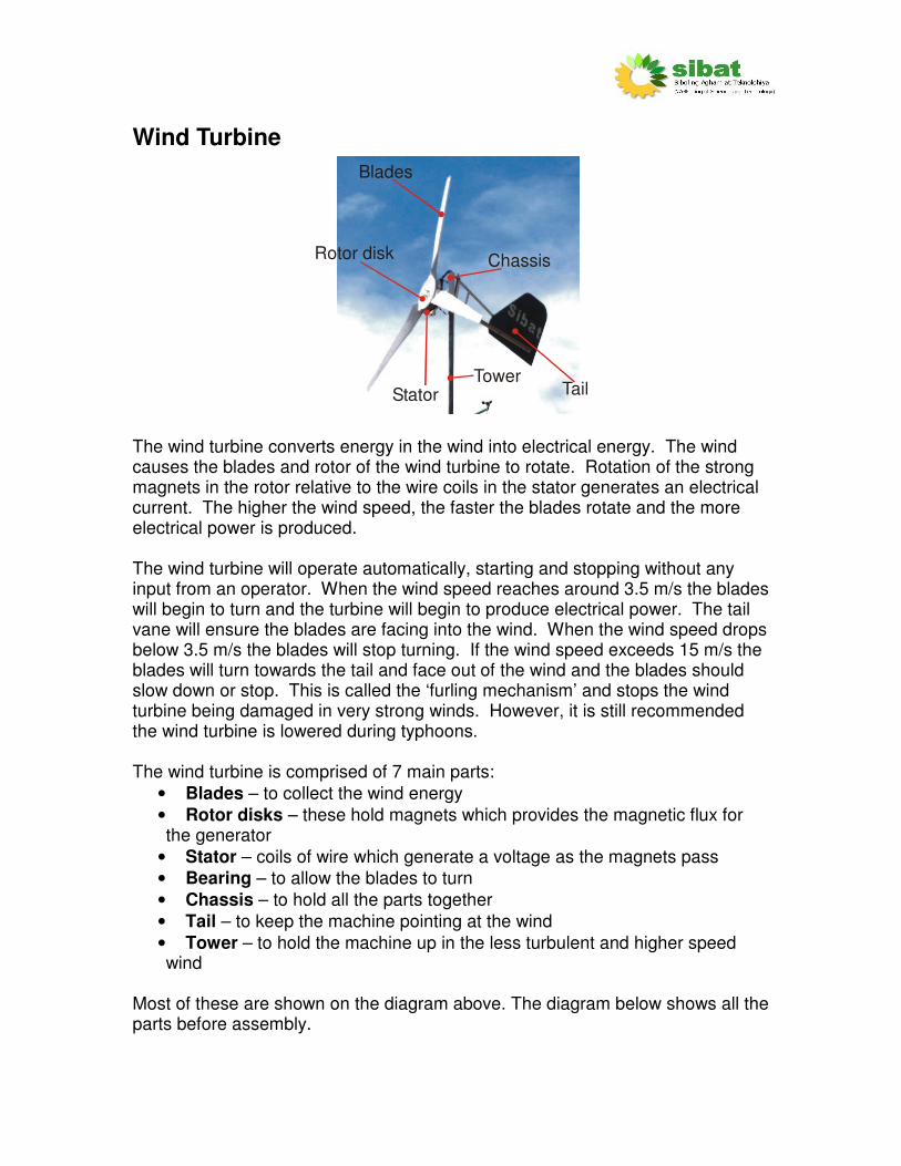
Wind Turbine
Blades
ChassisRotor disk
Stator TailTower
The wind turbine converts energy in the wind into electrical energy. The wind causes the blades and rotor of the wind turbine to rotate. Rotation of the strong magnets in the rotor relative to the wire coils in the stator generates an electrical current. The higher the wind speed, the faster the blades rotate and the more electrical power is produced. The wind turbine will operate automatically, starting and stopping without any input from an operator. When the wind speed reaches around 3.5 m/s the blades will begin to turn and the turbine will begin to produce electrical power. The tail vane will ensure the blades are facing into the wind. When the wind speed drops below 3.5 m/s the blades will stop turning. If the wind speed exceeds 15 m/s the blades will turn towards the tail and face out of the wind and the blades should slow down or stop. This is called the ‘furling mechanism’ and stops the wind turbine being damaged in very strong winds. However, it is still recommended the wind turbine is lowered during typhoons. The wind turbine is comprised of 7 main parts:
• Blades – to collect the wind energy
• Rotor disks – these hold magnets which provides the magnetic flux for the generator
• Stator – coils of wire which generate a voltage as the magnets pass
• Bearing – to allow the blades to turn
• Chassis – to hold all the parts together
• Tail – to keep the machine pointing at the wind
• Tower – to hold the machine up in the less turbulent and higher speed wind
Most of these are shown on the diagram above. The diagram below shows all the parts before assembly.
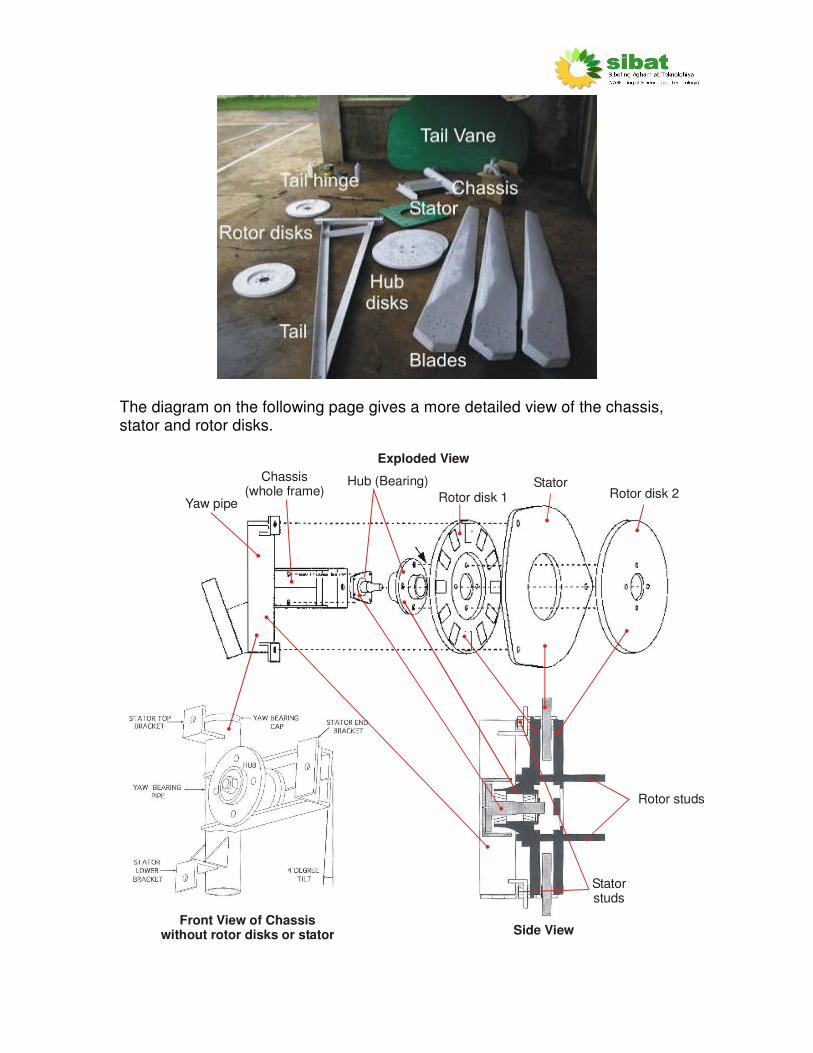
The diagram on the following page gives a more detailed view of the chassis, stator and rotor disks.
Exploded View
Side ViewFront View of Chassis
without rotor disks or stator
Hub (Bearing)
Rotor disk 1Stator
Rotor disk 2
Chassis(whole frame)
Rotor studs
Statorstuds
Yaw pipe
When discussing the wind turbine, the following terms and definitions are used:
• Chassis – refers to the metal mounting for the alternator and blades.
• Alternator – This is a general term for the electricity generation part, comprising the assembly of the two rotor disks and the stator.
• Rotor – refers to the rotating parts of the wind turbine including the blades and the rotor disks.
• Rotor disk – the turning part of the alternator that contains the magnets. Two rotor disks are required - front and rear.
• Stator – the stationary part of the alternator that contains the wire coils. Three cables from the alternator carry the output power to the rectifier. From the rectifier, two cables carry the power to the main system.
• Blades – the long white part shaped like an airplane wing. There are 3 blades. As the wind moves past the blades they are forced to rotate.
• Blade hub – the circular wooden disks that are screwed on the front and rear of the blades.
• Blade assembly – the assembly of the blades and blade hubs. A number of wood screws hold the blades onto the blade hubs.
• Yaw pipe / yaw bearing – the pipe on the side of the chassis. The yaw pipe sits on top of the tower. The cap on the top of the yaw pipe acts as a bearing surface so the wind turbine can rotate and turn into the wind. The hole in the cap is for the cable coming from the stator and going down the tower.
• Rotor studs – the four long studs attached to the bearing that hold the two rotor disks and blades.
• Stator studs – the four medium length studs that attach to the stator mounting lugs on the chassis and hole the stator in position.
• Stator mounting brackets – the four lugs welded on the chassis that the hold the stator studs, and hence the stator.
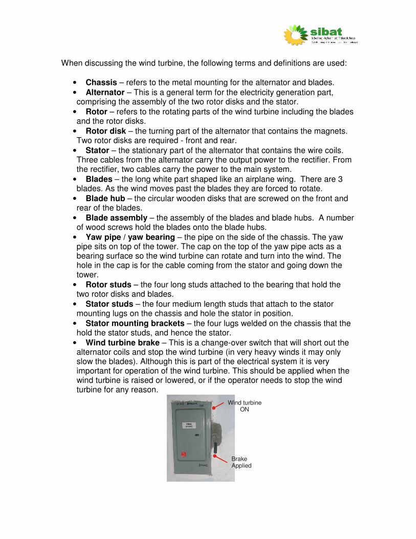
• Wind turbine brake – This is a change-over switch that will short out the alternator coils and stop the wind turbine (in very heavy winds it may only slow the blades). Although this is part of the electrical system it is very important for operation of the wind turbine. This should be applied when the wind turbine is raised or lowered, or if the operator needs to stop the wind turbine for any reason.
Brake Applied
Wind turbineON
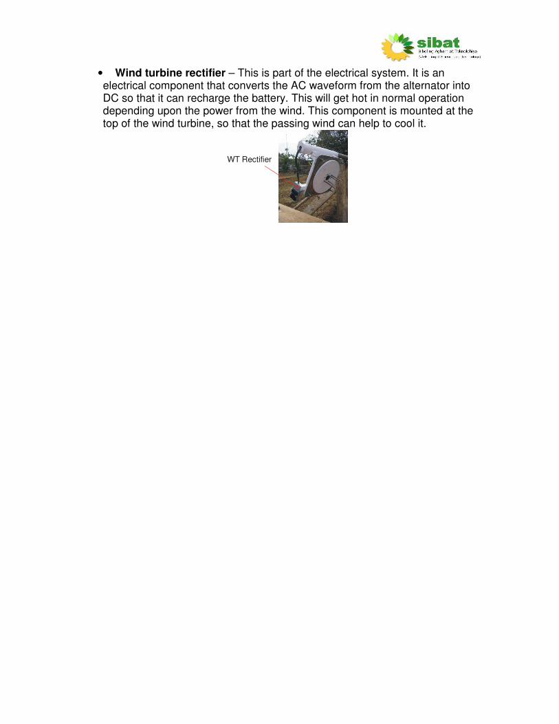
• Wind turbine rectifier – This is part of the electrical system. It is an electrical component that converts the AC waveform from the alternator into DC so that it can recharge the battery. This will get hot in normal operation depending upon the power from the wind. This component is mounted at the top of the wind turbine, so that the passing wind can help to cool it.
WT Rectifier

Safety
General safety
• Never climb the tower to inspect the turbine. The wind turbine should always be lowered to the ground.
• Keep people away from the area directly under the wind turbine at all times. If possible, fence off this area.
Wind turbine maintenance safety
• Careful of strong magnets. When disassembled the two rotor disks should be kept separate. The disks should also be kept away from and steel or magnetic items that may scratch or dirty the surface.
• Careful of rotating machinery
• Always apply the electrical brake to minimize risk of electric shock.
Raising and lowering tower
Safety
• This should not be attempted if there are insufficient people.
• Always apply electrical brake.
• Erect and lower the wind turbine in times of low wind.
• Always follow the correct procedure to erect and lower the tower (explained in this guide).
• Keep people away from raise/lower area while raising or lowering
View from above
Anchor point 1
BaseAnchor point 2
Anchor point 3
Anchor point 4
Anchor point 5
DANGER AREAKEEP PEOPLE AWAY
DANGER AREAKEEP PEOPLE AWAY
DANGER AREAS - KEEP PEOPLE AWAY
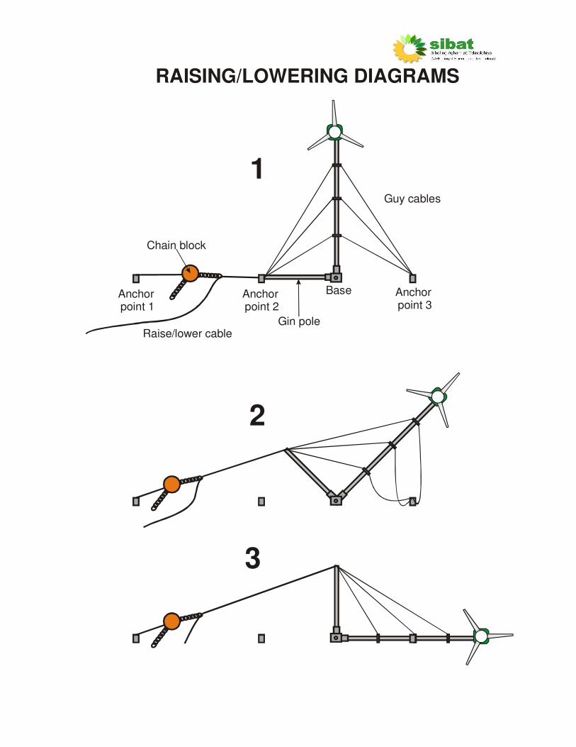
Raise/lower cable
Anchor point 1
Base
Gin pole
Chain block
Guy cables
Anchor point 2
Anchor point 3
3
2
1
RAISING/LOWERING DIAGRAMS

Wind turbine lowering process
1. Organise items required:
• Chain block - check this is in good condition
• 13mm Spanners x 4
• Raise/lower steel cable - check this is in good condition
• Cable clamps - check these are in good condition
• Gin pole and pin
• At least 3 people
2. Assign jobs to people:
• One or two people to operate chain block
• One person to watch for tension in the guy wires
• One person to ensure safety and that people are not in the vicinity of the wind turbine fall area.
3. Apply the wind turbine brake (in the powerhouse).
If possible raise and lower the turbine on a calm day.
4. Insert the gin pole into hole in the wind turbine base. Place the pin (made from a piece of rebar) through the hole in the wind turbine base and the gin pole. This is to stop the gin pole being pulled out of the wind turbine base. The pin should be kept with the other items.
5. Attach chain block to anchor point 1 using steel cable.
The steel cable must be looped around the anchor point and attached with THREE cable clamps (see diagram in stage 8). This cable will take the full weight of the wind turbine so ensure this is secure.
6. Ensure the heavy lifting chain is correctly fitted into the chain block with
no twisted links. 7. Attach the raise/lower cable to the lifting chain and to the gin pole.
Ensure THREE cable clamps are used at each fastening point.
8. At this point the apparatus should look like:
Anchor point 1
View from above
Ensure 3 cable clampson each loop
Cable clamp Chain
BlockLiftingchain
Smallchain
Raise/lowercable
Gin Pole
9. Ensure slight tension in the raise lower cable. This is required to
ensure the tower does not fall when the guy cables are changed from anchor point 2 and onto the gin pole (steps 10 to13). This can be done by winding in the chain block until there is tension within the raise/lower cable.
10. Now you must detach the guy cables from anchor point 2 and
reconnect them to the loop on the end of the gin pole. Do this one at a time, starting with the outer guy cable.
11. Disconnect the outer guy cable. Be careful when doing this as there
may be tension in the cable which may cause it to move suddenly.
12. Connect the outer guy cable to anchor point 2. Always ensure THREE guy cable clamps are used and that they are securely tightened.
13. Repeat steps 10 to 12 with the other two guy cables.
Ensure that there is similar tension in the three guy cables, so that the tower will be straight when lowered.
14. The guy wires at anchor points 4 and 5 can be loosened by slackening
their turnbuckles. This is to ensure that any tension that may occur due to misalignment of the anchor points, when the tower is lowered, does not result in the tower bending to either side. The tension in these side guy wires should be checked at regular intervals during the lowering procedure.
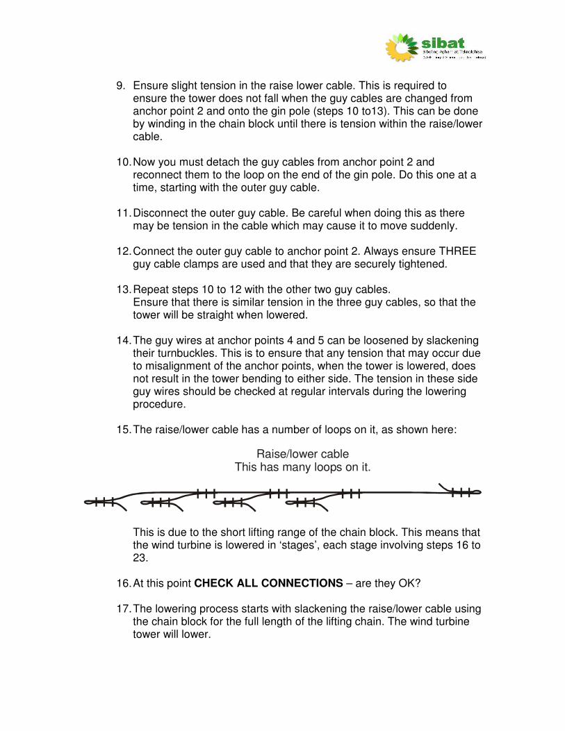
15. The raise/lower cable has a number of loops on it, as shown here:
Raise/lower cableThis has many loops on it.
This is due to the short lifting range of the chain block. This means that the wind turbine is lowered in ‘stages’, each stage involving steps 16 to 23.
16. At this point CHECK ALL CONNECTIONS – are they OK?
17. The lowering process starts with slackening the raise/lower cable using
the chain block for the full length of the lifting chain. The wind turbine tower will lower.
18. When the lifting chain has been extended almost fully (but not quite as far as the chain can go) through the chain block, the raise/lower cable must then be secured onto anchor point 1. This is done by looping the raise/lower cable around anchor point 1 and securing with THREE cable clamps. Ensure that the raise/lower cable is secured well.
19. The chain block is then slackened (using the final part of the lifting
chain). The weight will then be taken by the raise/lower cable and the lifting chain will be loose. The lifting chain can then be released from the loop on the raise/lower cable.
20. The lifting chain is then wound back to its shortest length.
21. The lifting chain can then be attached to the next of the raise/lower
cable loops. 22. The lifting chain is then pulled in to take the weight of the wind turbine.
This will allow the raise/lower cable to be released. Disconnect the raise/lower cable from anchor point 1.
23. The lifting chain can then be slackened again and the process
repeated from step 16 until the wind turbine is fully lowered. Take this process slowly. Check all the cable tensions many times. If anything feels too tight or shows any sign of bending STOP! Find the problem and correct it.
24. The greatest strain on the cable will be at the end of the lowering process (shown in number 3 of the raising/lowering diagrams).
25. When lowered, support the tower with a number of cross-braces (made
from wood or bamboo) along the length of the tower. Now breathe and relax, the lowering process is finished.
26. The raise/lower cable can then be disconnected and stored, along with
the chain block and other tools in a dry place. It is advised to grease the chain block each time it is used.
Wind turbine raising process
1. Organise items required:
• Chain block - check this is in good condition
• 13mm Spanners x 4
• Raise/lower steel cable - check this is in good condition
• Cable clamps - check these are in good condition
• Gin pole –already be in place as it was used during lowering
• At least 3 people

2. Assign jobs to people:
• One or two people to operate chain block
• One person to watch for tension in the guy wires
• One person to ensure safety and that people are not in the vicinity of the wind turbine fall area.
3. Apply the wind turbine brake (in the powerhouse).
If possible raise and lower the turbine on a calm day. 4. Attach chain block to anchor point 1 using steel cable.
The cable must be looped around the anchor point and attached with THREE cable clamps (see diagram in stage 7). This cable will take the full weight of the wind turbine so ensure this is secure.
5. Ensure the heavy lifting chain is correctly fitted into the chain block with no twisted links.
6. Attach the raise/lower cable to the lifting chain and to the gin pole.
7. At this point the apparatus should look like:
Anchor point 1
View from above
Ensure 3 cable clampson each loop
Cable clamp Chain
BlockLiftingchain
Smallchain
Raise/lowercable
Gin Pole
8. The raise/lower cable has a number of loops on it, as shown here:
Raise/lower cableThis has many loops on it.

This is due to the short lifting range of the chain block. This means that the wind turbine is raised in ‘stages’, each stage involving steps 9 to 16.
9. At this point CHECK ALL CONNECTIONS – are they OK? Is the tower
leaning to one side? Do the guy wires feel too tight?
10. The lifting process starts with pulling the raise/lower cable using the chain block for the full length of the lifting chain. The wind turbine tower will rise. The greatest strain on the cable will be at the start of the raising process (shown in number 3 of the raising/lowering diagrams).
11. When the lifting chain has been pulled fully through the chain block, the
raise/lower cable must then be secured onto anchor point 1. This is done by looping the raise/lower cable around anchor point 1 and securing with THREE cable clamps. Ensure that the raise/lower cable is secured well.
12. The chain block is then slackened (by reversing the direction of the
chain block and hence loosening the lifting chain). The weight will then be taken by the raise/lower cable. The lifting chain can then be released from the loop on the raise/lower cable.
13. The lifting chain is then extended to its full range.
14. The lifting chain can then be attached to the next of the raise/lower
cable loops. 15. The lifting chain is then pulled in to take the weight of the wind turbine.
This will allow the raise/lower cable to be released. Disconnect the raise/lower cable from anchor point 1.
16. The lifting chain can then be pulled in again and the process repeated
from step 9 until the wind turbine is fully raised. Take this process slowly. Check all the cable tensions many times. If anything feels too tight or shows any sign of bending STOP! Find the problem and correct it, even if it means lowering the tower.
17. When the wind turbine is fully raised (diagram 3), the guy cables need to be attached to anchor point 2. Do this one at a time, starting with the outer guy cable.
18. Disconnect the outer guy cable. Careful when this is done as there
may be tension in the cable which may cause it to move suddenly.
19. Connect the outer guy cable to anchor point 2.
20. Repeat with the other two guy cables.
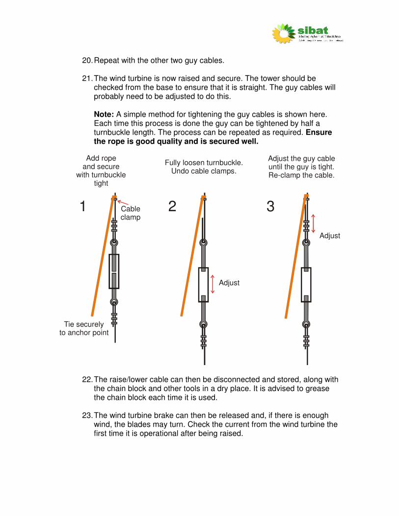
21. The wind turbine is now raised and secure. The tower should be
checked from the base to ensure that it is straight. The guy cables will probably need to be adjusted to do this. Note: A simple method for tightening the guy cables is shown here. Each time this process is done the guy can be tightened by half a turnbuckle length. The process can be repeated as required. Ensure the rope is good quality and is secured well.
Cable clamp
Add ropeand secure
with turnbuckle tight
Tie securelyto anchor point
Fully loosen turnbuckle.Undo cable clamps.
Adjust
Adjust
Adjust the guy cableuntil the guy is tight.Re-clamp the cable.
1 2 3
22. The raise/lower cable can then be disconnected and stored, along with the chain block and other tools in a dry place. It is advised to grease the chain block each time it is used.
23. The wind turbine brake can then be released and, if there is enough
wind, the blades may turn. Check the current from the wind turbine the first time it is operational after being raised.
Wind turbine assembly
1. Begin with the chassis laid flat on its back (the yaw pipe should be on the left hand side).
2. Bolt the bearing to the chassis. Use washers both sides and two nuts to
lock.
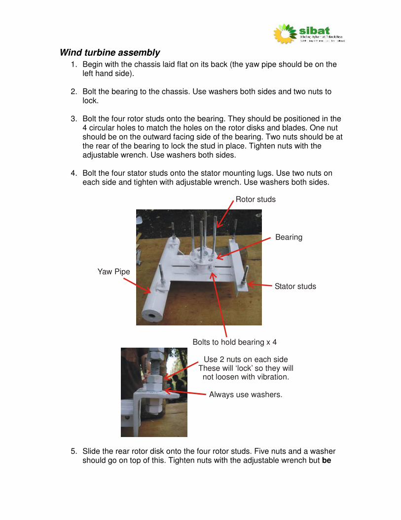
3. Bolt the four rotor studs onto the bearing. They should be positioned in the 4 circular holes to match the holes on the rotor disks and blades. One nut should be on the outward facing side of the bearing. Two nuts should be at the rear of the bearing to lock the stud in place. Tighten nuts with the adjustable wrench. Use washers both sides.
4. Bolt the four stator studs onto the stator mounting lugs. Use two nuts on
each side and tighten with adjustable wrench. Use washers both sides.
Stator studs
Yaw Pipe
Bolts to hold bearing x 4
Bearing
Rotor studs
Use 2 nuts on each sideThese will ‘lock’ so they willnot loosen with vibration.
Always use washers.
5. Slide the rear rotor disk onto the four rotor studs. Five nuts and a washer
should go on top of this. Tighten nuts with the adjustable wrench but be

careful as the magnets in the rotor will attract the steel spanner. Use washers both sides.
6. Position 2 more nuts on to each stator stud. Slide the stator down to sit on the two nuts. There should be an air gap between the stator and the rotor disk of about 2mm. Screw two more nuts on top of the stator. Use washers both sides. Do not tighten the nuts yet so you can adjust later.
Ensure that the stator is level and that the rotor can easily spin around without
touching. The gap should be approximately 1 to 2 mm.

7. Slide the front rotor disk onto the four rotor studs. Ensure that the front and back rotor disks are correctly aligned with each other. The mark on the edge of the front rotor disk must be in line with the mark on the edge of the rear rotor disk. Be careful of trapping fingers as the rotor disk will fall sharply as it is attracted by the magnets. In order to stop this, use pieces of wood or bamboo, these can then be slowly eased out. Add a washer and a nut on top of the rotor disk on each rotor stud.
8. Turn the rotor disks using the rotor studs. They should be able to turn
without touching the stator. An air gap of about 1 to 2mm should be maintained between the stator and the rotor on each side. The stator can be moved up and down by turning the nuts holding the stator in place. Adjust until an air gap of approx. 2mm is between the stator and rotor on both sides.
Spin rotor disks to ensure they do not touch the stator.
Ensure that the gaps here are approx 1-2mm
Rotor Disks Stator
9. The chassis and alternator can now be placed onto the tower. Apply grease onto the top part of the tower tube in order to lubricate the yaw bearing. The wires connecting the stator to the tower cable wires should be connected.
Ensure these entry points are sealed
Apply sealant around lid beforesealing the box
2 x DC CablesThese go down
the tower
3 x AC CablesThese go to the stator
Ensure correctpolarity
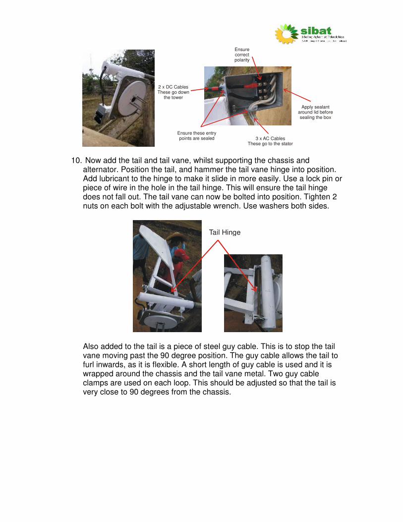
10. Now add the tail and tail vane, whilst supporting the chassis and
alternator. Position the tail, and hammer the tail vane hinge into position. Add lubricant to the hinge to make it slide in more easily. Use a lock pin or piece of wire in the hole in the tail hinge. This will ensure the tail hinge does not fall out. The tail vane can now be bolted into position. Tighten 2 nuts on each bolt with the adjustable wrench. Use washers both sides.
Tail Hinge
Also added to the tail is a piece of steel guy cable. This is to stop the tail vane moving past the 90 degree position. The guy cable allows the tail to furl inwards, as it is flexible. A short length of guy cable is used and it is wrapped around the chassis and the tail vane metal. Two guy cable clamps are used on each loop. This should be adjusted so that the tail is very close to 90 degrees from the chassis.
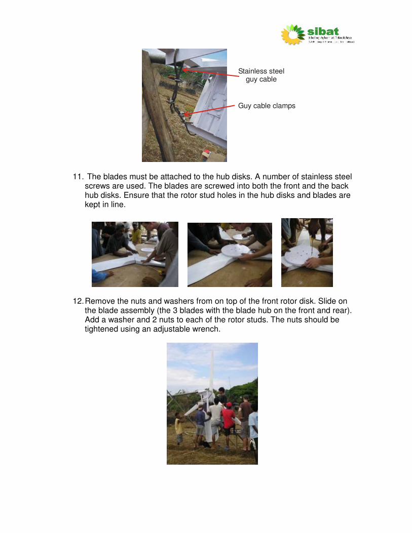
Stainless steel guy cable
Guy cable clamps
11. The blades must be attached to the hub disks. A number of stainless steel
screws are used. The blades are screwed into both the front and the back hub disks. Ensure that the rotor stud holes in the hub disks and blades are kept in line.
12. Remove the nuts and washers from on top of the front rotor disk. Slide on
the blade assembly (the 3 blades with the blade hub on the front and rear). Add a washer and 2 nuts to each of the rotor studs. The nuts should be tightened using an adjustable wrench.
13. Note: This section is only required when first assembled. The blades must now be balanced. Even if they had been balanced in the workshop, there will be differences when the blade assembly is attached to the alternator. To balance the blades first ensure that it is a very calm day – any wind may affect the results. Then, with the blades perpendicular to the ground, release the blades gently (ensure that the blades are not spun at all). If the blades are balanced then they should not turn. If the blades do turn, wait until the blades have stopped. This should mean that the heaviest part is at the bottom. Weight, in the form of a nut and bolt, or any other weight, can be added to the rotor disk at the point above where the blades had come to rest (i.e. add weight on the other side to balance the blades). Continue this process until the blades are balanced. Ensure that the weights are very well attached, as they could be dangerous if they were to come loose.
Wind turbine disassembly
1. First lower the wind turbine to the ground. Follower the lowering procedure. Support the blade assembly and alternator so they do not hit the ground.
2. Remove the tail vane as a whole unit. To do this, first disconnect the piece
of cable by undoing the cable clamps. Then remove the securing pin in the tail hinge. The tail hinge can then be removed, usually by hammering the end.
3. Unscrew the four nuts holding the blade assembly in place and remove
the blade assembly as a whole unit. This can be quite difficult and may require a number of wedges to be driven in between the front rotor disk and the blade hub disk. Ensure the blades are not used to pull the blade assembly.
4. Remove the sealant from around the two main power cables at the entry
point of the rectifier box and disconnect the two wires.
5. The chassis and alternator can now be taken off the tower. Lay the chassis flat on its back on a horizontal surface.
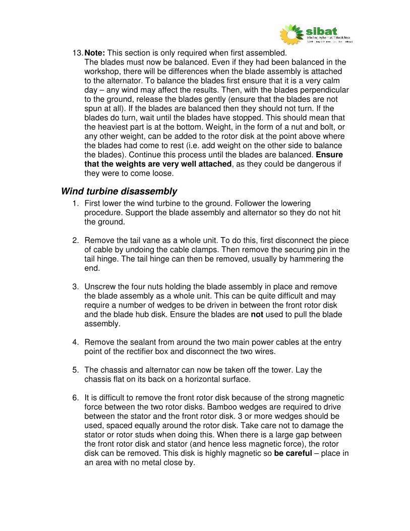
6. It is difficult to remove the front rotor disk because of the strong magnetic
force between the two rotor disks. Bamboo wedges are required to drive between the stator and the front rotor disk. 3 or more wedges should be used, spaced equally around the rotor disk. Take care not to damage the stator or rotor studs when doing this. When there is a large gap between the front rotor disk and stator (and hence less magnetic force), the rotor disk can be removed. This disk is highly magnetic so be careful – place in an area with no metal close by.
7. Remove the nuts holding the stator. The stator can then be removed.
8. Unbolt the rear rotor disk and remove. Store in a different place from the front rotor disk. Take care as the strong magnetism can pull the two rotor disks together and trap fingers.
9. If required, remove the nuts and rotor studs from the bearing.
Maintenance
The wind turbine should be lowered and inspected every year. If lowered due to a typhoon it would be a good idea to perform a maintenance check before the wind turbine is raised again.
Lower the wind turbine - follow raise/lower procedure in wind turbine chapter.
• Cleaning The blades should be cleaned with soapy water to remove any dirt or salt. Inspect the blades for cracks, holes, rust, fatigue or bent sections and make a note in the operation and maintenance log book.
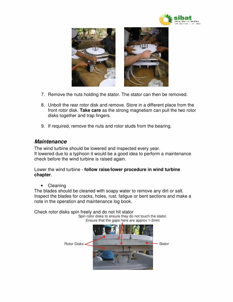
Check rotor disks spin freely and do not hit stator
Spin rotor disks to ensure they do not touch the stator.Ensure that the gaps here are approx 1-2mm
Rotor Disks Stator

• Painting. All painted steel parts on the wind turbine, tower and foundations should be painted periodically to prevent rusting. This includes:
o Chassis and yaw pipe o Tail o Bearing o Guy wire connecting strips o Guy wire foundation posts o Tower base and hinge
If the parts are already rusty, apply rust remover and clean the part, then apply a fresh coat of paint. The wooden tail vane should also be painted periodically. After a few years the tail vane may become weathered and cracked. This can be replaced with wood of an equivalent size, shape and weight.
• Lubrication The wind turbine chassis rotates around the top of the tower to follow the wind. The point of rotation (where the chassis sits on top of the tower) is called the yaw bearing. This bearing must be kept lubricated to ensure easy rotation of the turbine. To do this, apply grease to the tube at the top of the tower before the chassis is placed onto the tower.
Chassis
Top of tower
Applygreasehere
• Check bearing Ensure that the bearing rotates freely but without any ‘wobble’. If any noise can be heard from the bearing or it does not rotate correctly then replace the bearing.
Spin rotor disks to check bearing.

• Cable twist Two power cables go from the rectifier box, down the tower and to the power house. It is possible that these cables can become twisted due to the rotation of the wind turbine chassis on the tower. When the wind turbine is lowered, check to see if the cables have become too twisted. If they are, then rectify this by disconnecting the positive and negative terminals from the rectifier within the rectifier box. You may need to cut away the sealant on the entry point to the rectifier box. Untwist the cables manually. When untwisted reconnect the terminals ensuring the correct polarity.
Ensure these entry points are sealed
Apply sealant around lid beforesealing the box
2 x DC CablesThese go down
the tower
3 x AC CablesThese go to the stator
Ensure correctpolarity
Re-apply sealant to the cable entry points to the rectifier box and around the lid of the rectifier box. Tightly fasten the lid screws to ensure that the rectifier box is fully sealed. Note: This system does not use a waterproof box. Future systems should. When everything has been checked, raise the turbine (follow raise/lower procedure in the ‘wind turbine’ chapter).
• Lastly, check tower and turnbuckles Ensure they are all tight and that the tower is straight.
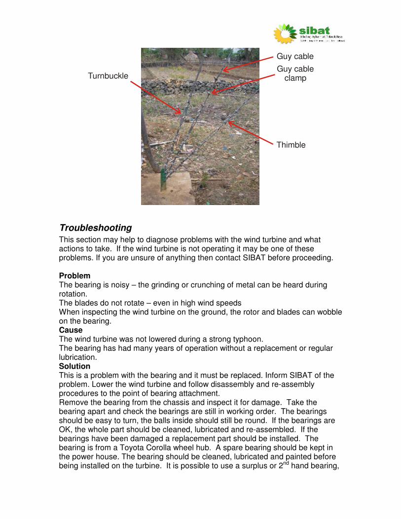
Guy cable
Guy cable clamp
Thimble
Turnbuckle
Troubleshooting
This section may help to diagnose problems with the wind turbine and what actions to take. If the wind turbine is not operating it may be one of these problems. If you are unsure of anything then contact SIBAT before proceeding. Problem The bearing is noisy – the grinding or crunching of metal can be heard during rotation. The blades do not rotate – even in high wind speeds When inspecting the wind turbine on the ground, the rotor and blades can wobble on the bearing. Cause The wind turbine was not lowered during a strong typhoon. The bearing has had many years of operation without a replacement or regular lubrication. Solution This is a problem with the bearing and it must be replaced. Inform SIBAT of the problem. Lower the wind turbine and follow disassembly and re-assembly procedures to the point of bearing attachment. Remove the bearing from the chassis and inspect it for damage. Take the bearing apart and check the bearings are still in working order. The bearings should be easy to turn, the balls inside should still be round. If the bearings are OK, the whole part should be cleaned, lubricated and re-assembled. If the bearings have been damaged a replacement part should be installed. The bearing is from a Toyota Corolla wheel hub. A spare bearing should be kept in the power house. The bearing should be cleaned, lubricated and painted before being installed on the turbine. It is possible to use a surplus or 2nd hand bearing,
however the performance will probably not be as good, with a shorter expected life. Cost Approximately Php 1000 for a 2nd hand bearing. Problem The wind turbine is not rotating during strong winds after a lightning storm in the area. The wind turbine is most likely the tallest object in the area – making it a perfect target for lightning. Cause The wind turbine has had a direct lightning strike. The high voltage of the lightning strike can damage electrical components or melt or burn turbine parts. Solution Lower the wind turbine. If major damage has occurred it should be visible – most probably as a blackened burnt patch. The blades or tail may be damaged. The wire cable returning to the ground may be burnt. SIBAT should be informed of any major lightning strikes and the resulting damage. A lightning rod has been installed to carry try to protect the electrical equipment in the power house. This should be maintained for damage limitation. Cost Unable to say – depends upon extent of damage. Problem Cracks appear in the polyester resin casing of the stator. Cause The polyester resin casing for the stator has fatigued. The stator is heated by the wire coils embedded in the polyester resin. Heating and cooling of the stator, plus being subject to direct sunlight can cause the polyester resin to corrode and crack. Solution If the cracks in the stator are small it is possible to fill them with a sealant or filler (such as car body filler). It is important the part remains watertight. If the cracks grow and expose lots of wires and distort the part SIBAT should be informed Cost Replacement stator cost approx Php 6000. Problem The blades are damaged. During operation the blades make a louder noise than usual. Inspection from the ground, or when the wind turbine has been lowered may reveal cracks in the blades, or the blades are bent out of shape. Cause Strong wind has caused the joints in the fiberglass material to come apart. Direct sunlight for a number of years can cause damage to the fiberglass. Solution

SIBAT should be informed. If major damage has occurred to the blade SIBAT should be informed and other blades can be ordered. Cost Replacement set of blades cost approx. Php 10000
Solar Panels
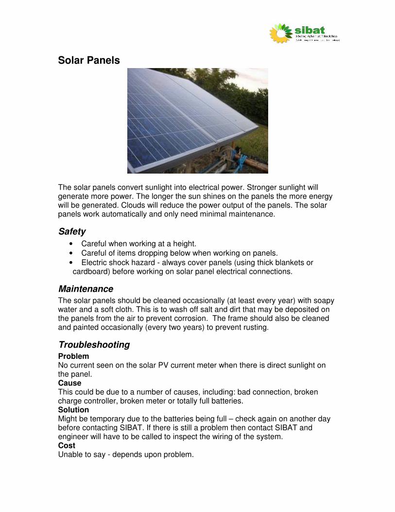
The solar panels convert sunlight into electrical power. Stronger sunlight will generate more power. The longer the sun shines on the panels the more energy will be generated. Clouds will reduce the power output of the panels. The solar panels work automatically and only need minimal maintenance.
Safety
• Careful when working at a height.
• Careful of items dropping below when working on panels.
• Electric shock hazard - always cover panels (using thick blankets or cardboard) before working on solar panel electrical connections.
Maintenance
The solar panels should be cleaned occasionally (at least every year) with soapy water and a soft cloth. This is to wash off salt and dirt that may be deposited on the panels from the air to prevent corrosion. The frame should also be cleaned and painted occasionally (every two years) to prevent rusting.
Troubleshooting
Problem No current seen on the solar PV current meter when there is direct sunlight on the panel. Cause This could be due to a number of causes, including: bad connection, broken charge controller, broken meter or totally full batteries. Solution Might be temporary due to the batteries being full – check again on another day before contacting SIBAT. If there is still a problem then contact SIBAT and engineer will have to be called to inspect the wiring of the system. Cost Unable to say - depends upon problem.
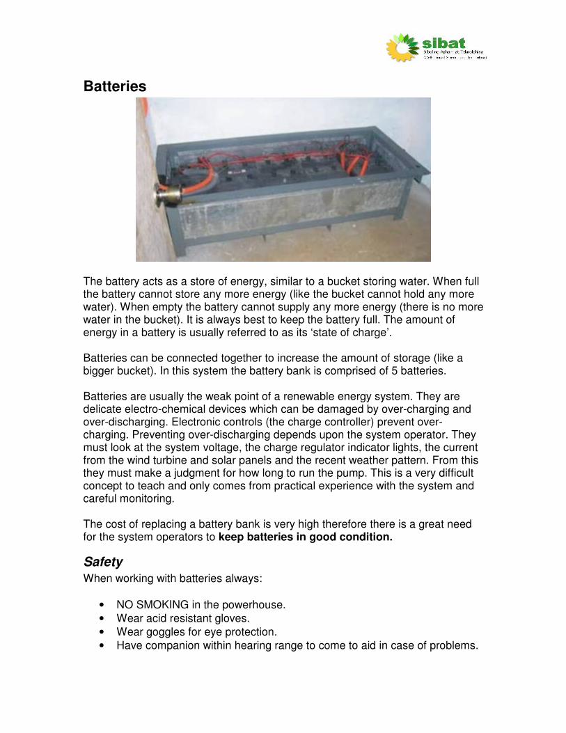
Batteries
The battery acts as a store of energy, similar to a bucket storing water. When full the battery cannot store any more energy (like the bucket cannot hold any more water). When empty the battery cannot supply any more energy (there is no more water in the bucket). It is always best to keep the battery full. The amount of energy in a battery is usually referred to as its ‘state of charge’. Batteries can be connected together to increase the amount of storage (like a bigger bucket). In this system the battery bank is comprised of 5 batteries. Batteries are usually the weak point of a renewable energy system. They are delicate electro-chemical devices which can be damaged by over-charging and over-discharging. Electronic controls (the charge controller) prevent over-charging. Preventing over-discharging depends upon the system operator. They must look at the system voltage, the charge regulator indicator lights, the current from the wind turbine and solar panels and the recent weather pattern. From this they must make a judgment for how long to run the pump. This is a very difficult concept to teach and only comes from practical experience with the system and careful monitoring. The cost of replacing a battery bank is very high therefore there is a great need for the system operators to keep batteries in good condition.
Safety
When working with batteries always:
• NO SMOKING in the powerhouse.
• Wear acid resistant gloves.
• Wear goggles for eye protection.
• Have companion within hearing range to come to aid in case of problems.

• Have plenty of fresh water and soap around in case of battery acid contacting skin, clothes etc.
• If acid splashed onto clothes or skin wash thoroughly with soap and clean water.
• If acid splashed into eye flush with clean water for a least 20min and immediately get medical attention (this may be difficult on Cabra Island so ALWAYS WEAR EYE PROTECTION).

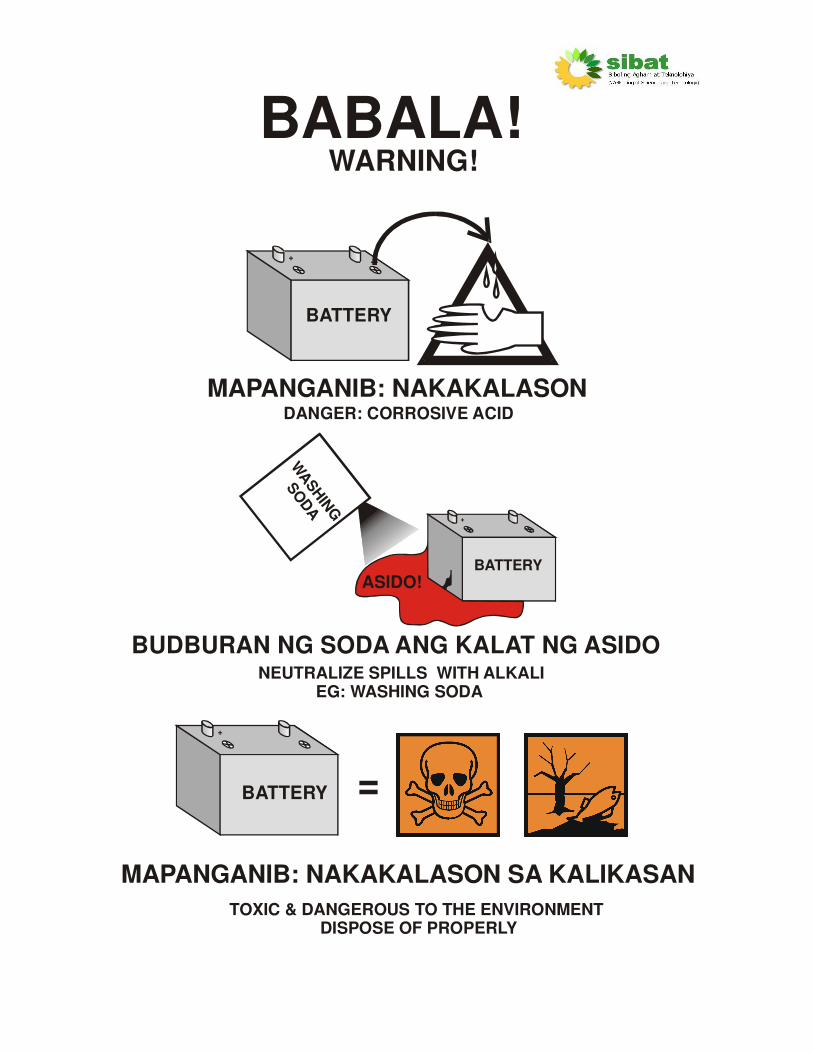
WARNING!
BATTERY
+
DO NOT SHORT
ELECTRONICS(INVERTER ETC)
KEEP ELECTRICS DRY
BATTERY
+
NO FLAMES
BAWAL MANIGARILYO+
HEAVY! CAREFUL LIFTING
!
MABIGAT!INGAT SA PAGBUHAT
BABALA!
PANATILIHING TUYO
HUWAG LALAPATANNG METAL
BABALA!
BATTERY
+
DANGER: CORROSIVE ACID
MAPANGANIB: NAKAKALASON
TOXIC & DANGEROUS TO THE ENVIRONMENT DISPOSE OF PROPERLY
MAPANGANIB: NAKAKALASON SA KALIKASAN
+
=BATTERY
WARNING!
NEUTRALIZE SPILLS WITH ALKALIEG: WASHING SODA
BATTERY
+
ASIDO!
WASH
ING
SO
DA
BUDBURAN NG SODA ANG KALAT NG ASIDO

Maintenance
Testing voltage: Do this every day.
The system voltage meter shows the system (battery bank) voltage.
This voltage is the most important system parameter. If the pump is NOT running then this voltage shows how full the battery bank is. This shown here:
13121110 14 15 16
FULL
OVER-CHARGE
EMPTY
DO NOT RUN PUMP
SYSTEM VOLTAGE
If the battery voltage is below 13V or there is no green light displayed on the charge controller then do not run the pump. If the voltage is lower than 11V for a length of time, even with sun or wind, then something is wrong – contact SIBAT. If the voltage stays over 16V for a length of time (more than half and hour) then something is wrong – contact SIBAT.
Clean batteries:
Do this every month. Warning: there could be battery acid present. Wear goggles and acid-resistant gloves. Wipe the tops with a slightly damp cloth then dry thoroughly.
Check battery water levels: Do this every month.
Warning: there could be battery acid present. Wear goggles and acid-resistant gloves.
Take each battery in turn. Remove the caps from the battery If any grey metal can be seen, then the levels are too low. The battery should be filled nearly to the top with DISTILLED water. Then replace the lids.
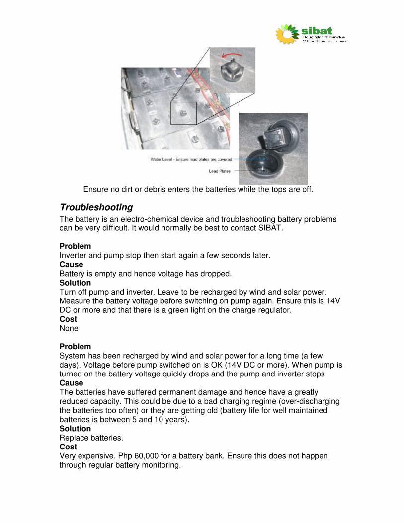
Ensure no dirt or debris enters the batteries while the tops are off.
Troubleshooting
The battery is an electro-chemical device and troubleshooting battery problems can be very difficult. It would normally be best to contact SIBAT. Problem Inverter and pump stop then start again a few seconds later. Cause Battery is empty and hence voltage has dropped. Solution Turn off pump and inverter. Leave to be recharged by wind and solar power. Measure the battery voltage before switching on pump again. Ensure this is 14V DC or more and that there is a green light on the charge regulator. Cost None Problem System has been recharged by wind and solar power for a long time (a few days). Voltage before pump switched on is OK (14V DC or more). When pump is turned on the battery voltage quickly drops and the pump and inverter stops Cause The batteries have suffered permanent damage and hence have a greatly reduced capacity. This could be due to a bad charging regime (over-discharging the batteries too often) or they are getting old (battery life for well maintained batteries is between 5 and 10 years). Solution Replace batteries. Cost Very expensive. Php 60,000 for a battery bank. Ensure this does not happen through regular battery monitoring.

Controls The controls ensure that the system works correctly. The various components are shown here along with a basic description of their purpose.
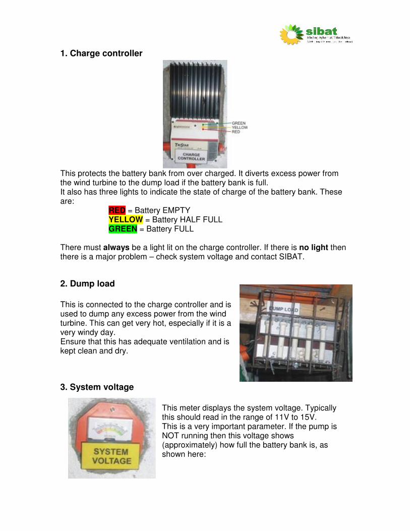
1. Charge controller
This protects the battery bank from over charged. It diverts excess power from the wind turbine to the dump load if the battery bank is full. It also has three lights to indicate the state of charge of the battery bank. These are:
RED = Battery EMPTY YELLOW = Battery HALF FULL GREEN = Battery FULL
There must always be a light lit on the charge controller. If there is no light then there is a major problem – check system voltage and contact SIBAT.
2. Dump load
This is connected to the charge controller and is used to dump any excess power from the wind turbine. This can get very hot, especially if it is a very windy day. Ensure that this has adequate ventilation and is kept clean and dry.
3. System voltage
This meter displays the system voltage. Typically this should read in the range of 11V to 15V. This is a very important parameter. If the pump is NOT running then this voltage shows (approximately) how full the battery bank is, as shown here:

13121110 14 15 16
FULL
OVER-CHARGE
EMPTY
DO NOT RUN PUMP
SYSTEM VOLTAGE
If the battery voltage is below 13V or there is no green light displayed on the charge controller then do not run the pump. If the voltage is lower than 11V for a length of time, even with sun or wind, there is a problem – contact SIBAT. If the voltage stays over 16V for a length of time (more than half and hour) then there is a problem – contact SIBAT.
4. Solar current
This meter shows the current (and hence power) coming from the solar panels. If there is sunlight on the panels then this meter should have a reading of between 5 and 30A. When dark, there will be no current generated so the meter will read zero. If it is a sunny day but there is no reading on this meter then firstly check the fuses on the solar panel regulator. If a fuse is blown try replacing with a 30A (green) blade-type automotive fuse. If this fuse blows as well then there is a problem - contact SIBAT.
5. Solar panel regulator
This ensures that the batteries do not get over-charged by the solar panels. This component can get very hot. Ensure that there is adequate ventilation around this component. There are four lights on this device.
Yellow sun = Generating power Green battery = full battery Red battery = empty battery Green light bulb = NOT USED The yellow light should be lit if there is any current shown on the solar current

WT Rectifier
meter. The green and red battery lights should indicate the approximate state of charge of the battery, similar to the charge controller.
6. Wind current
This meter shows the current (and hence power) coming from the wind turbine. If there is wind and the wind turbine blades are spinning then this meter should have a reading of between 0 and 80A. If there is no or very light wind then there will be no current generated so the meter will read zero. If it is a windy day and the wind turbine blades are spinning around but there is no reading on this meter then there is a problem – contact SIBAT.
7. Wind turbine rectifier
This converts the AC (alternating current) output of the wind turbine into the DC (direct current) level for required the batteries. This unit is placed at the top of the wind turbine tower. This will get hot in normal operation. The windier it is, the hotter this will get. The heatsink fins on the unit are designed to dissipate the heat generated. Ensure adequate ventilation (to do this the unit has been placed at the top of the tower, in the flow of the wind).
8. Pump current
This displays the current supplied to the pump at the bottom of the well. This should display approximately 8A when the pump is running (after a short start-up time of approximately 30 seconds) and zero if the pump is switched off.
9. Pump controls
This controls the operation of the pump. It ensures that the pump does not run dry and that it does not pump to overflow the storage tanks. When the pump is switched on the relays will make a ‘clicking’ sound. This is normal.
Maintenance
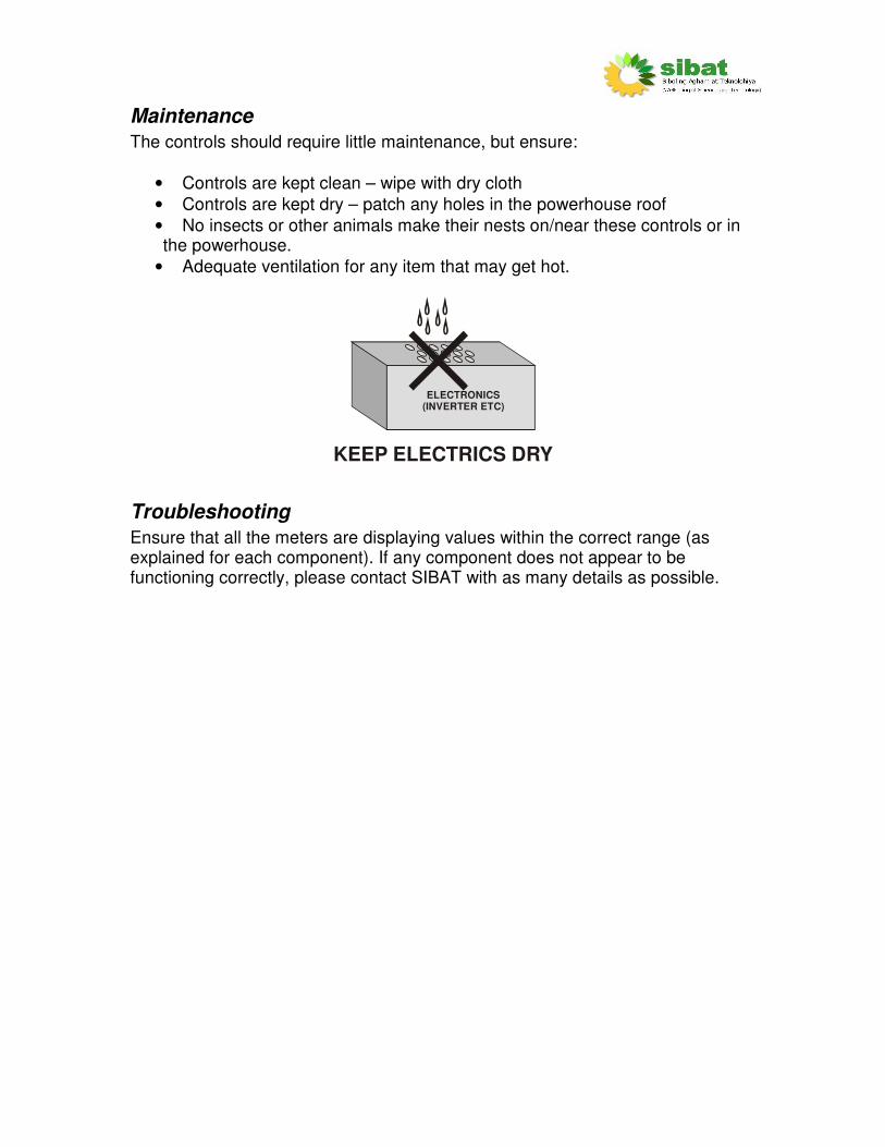
The controls should require little maintenance, but ensure:
• Controls are kept clean – wipe with dry cloth
• Controls are kept dry – patch any holes in the powerhouse roof
• No insects or other animals make their nests on/near these controls or in the powerhouse.
• Adequate ventilation for any item that may get hot.
ELECTRONICS(INVERTER ETC)
KEEP ELECTRICS DRY
Troubleshooting
Ensure that all the meters are displaying values within the correct range (as explained for each component). If any component does not appear to be functioning correctly, please contact SIBAT with as many details as possible.

Inverter The inverter converts the battery voltage to the voltage required by the pump. It is a complicated electronic device which should only be operated by the trained system operator.
Main controls
NOT USEDNOT USED
DOADJUST
NOT
DOADJUST
NOT
DOADJUST
NOT
DOADJUST
NOTDOADJUST
NOT
1POWERON/OFF
2GREEN
= OK
4NO LIGHT
= OK
3NO LIGHT
= OK
5NO LIGHT
= OK The only control that need to be checked or used by the system operator are:
1 Power ON/OFF button Press once, for approximately 1 second, to switch the inverter ON. Press again to switch the inverter OFF.

2 Inverter mode indicator This light will be GREEN if the inverter is ON and OK.
3 Overload indicator This light indicates an overload condition. If OFF then the inverter is OK. If GREEN then the inverter is overloaded. Check the pump current – this should not be greater than 9A.
4 Battery high/low indicator If OFF then the inverter is OK. If RED then the voltage is too high – check the system voltage meter. If possible, run the pump until this light is not lit. If GREEN then the voltage is too low – check the system voltage meter. Do not run the pump is this occurs.
5 Battery charger indicator This light should always be OFF.
Maintenance
The inverter should require little maintenance, but ensure:
• It is kept clean – wipe with dry cloth
• It is kept dry – patch any holes in the powerhouse roof
• No insects or other animals make their nests on/near these controls or in the powerhouse.
• Adequate ventilation as it may get hot – DO NOT cover any ventilation holes.
• NEVER open this device – it contains no user-serviceable parts.
ELECTRONICS(INVERTER ETC)
KEEP ELECTRICS DRY
Troubleshooting
Problem No lights on inverter Cause This could be caused by:
• No power
• Broken inverter
• Very low batteries Solution

This may require some input from SIBAT engineers, but firstly:
• Check system voltage – Is this in the correct range?
• Check breaker to unit closed – Is the inverter connected to the battery? Otherwise contact SIBAT. Cost Unable to say. Replacement inverter cost is approx. Php 70,000. Problem Inverter and pump stop then start again a few seconds later. Cause Battery is empty and hence voltage has dropped. Solution Turn off pump and inverter. Leave to be recharged by wind and solar power. Measure battery voltage before switching on pump. Ensure this is 14V DC or more and that there is a green light on the charge regulator. Cost None. Problem Inverter and pump stop then start again a few seconds later. With the overload light lit in GREEN. Cause The inverter is overloaded. Solution Check the current to the pump. Is this more than 9A? If yes – then stop and check the pump and water pipe. Is there a blockage? If no – then contact SIBAT. Cost Unable to say.
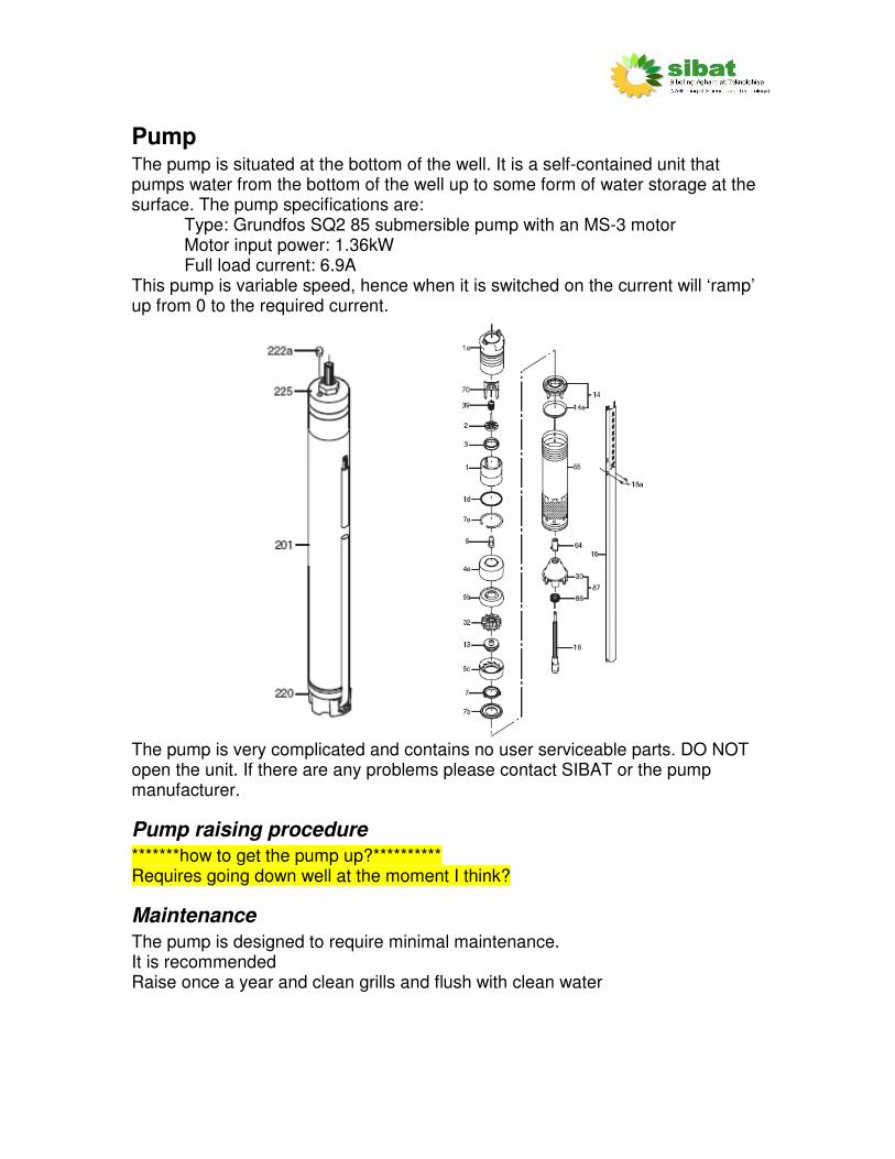
Pump The pump is situated at the bottom of the well. It is a self-contained unit that pumps water from the bottom of the well up to some form of water storage at the surface. The pump specifications are:
Type: Grundfos SQ2 85 submersible pump with an MS-3 motor Motor input power: 1.36kW Full load current: 6.9A
This pump is variable speed, hence when it is switched on the current will ‘ramp’ up from 0 to the required current.
The pump is very complicated and contains no user serviceable parts. DO NOT open the unit. If there are any problems please contact SIBAT or the pump manufacturer.
Pump raising procedure
*******how to get the pump up?********** Requires going down well at the moment I think?
Maintenance
The pump is designed to require minimal maintenance. It is recommended Raise once a year and clean grills and flush with clean water

Troubleshooting
Problem Pump stops then starts again a few seconds later. Cause Battery is empty and hence voltage has dropped. Solution Turn off pump and inverter. Leave to be recharged by wind and solar power. Measure battery voltage before switching on pump. Ensure this is 14V DC or more and that there is a green light on the charge regulator. Cost None Problem Water flow reduced or pump current is too high. Cause Blockage somewhere in the pipe. Solution Check pump and piping. Cost Unknown
Tools • All tools should be stored in the locked powerhouse.
• They should be cleaned and well maintained.
• Lending of the tools to members of the community may lead to ownership issues and reduce the life that the tools can be used for the project.
• It is always best to use the correct tool for the job. This will reduce the time taken and reduce the possibility of damage or injury occurring.
Tools for tower erection
*****Images of them*******
• Chain block This is used to raise and lower the wind turbine tower. It is VERY IMPORTANT that this item is kept in good condition The chain block should be cleaned and lubricated regularly (when ever used).
• Spanners These are used to undo and tighten the cable clamps to loosen the guy wires on the wind turbine. 13mm spanners are required for the cable clamps.
Tools for wind turbine servicing
In order to take apart the main wind turbine body the following tools may be required. *****Images of them*******
• Adjustable spanners
• Bamboo raisers (non-magnetic to take off rotor)
• Grease
• Screwdriver (cross-head)
• Hammer
Tools for electrical systems
It is not expected that any work should be carried out on the electrical system, but the following tools may be useful. *****Images of them*******
• Insulated spanner This is to tighten battery connections
• Multimeter
• Distilled water
• Acid resistant gloves
• Goggles
• Screw drivers (various sizes, cross and flat head)
• Self-amalgamating tape
Appendices Additional documents required include:
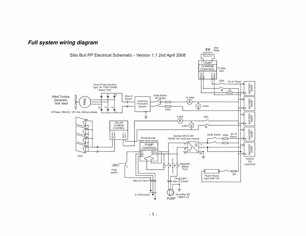
• Full system wiring diagram
• Component suppliers and contact details
• Manual for Tristar C-60 charge controller
• Manual for Trace SW1512 inverter
• Manual for Grundfos SQ2 85 submersible pump
- 1 -
Full system wiring diagram
V
PUMP
Power HouseLight 20W 12V
A
V
Dump
+ -
PM
G
A
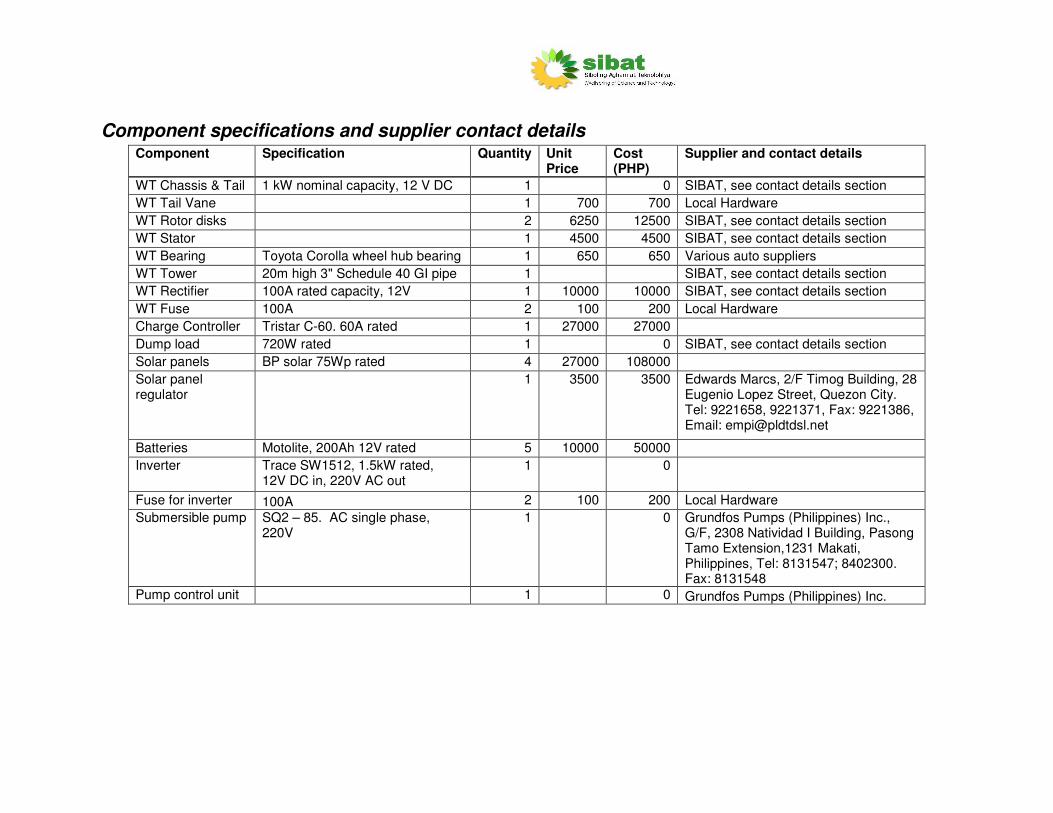
Component specifications and supplier contact details Component Specification Quantity Unit
Price Cost (PHP)
Supplier and contact details
WT Chassis & Tail 1 kW nominal capacity, 12 V DC 1 0 SIBAT, see contact details section
WT Tail Vane 1 700 700 Local Hardware
WT Rotor disks 2 6250 12500 SIBAT, see contact details section
WT Stator 1 4500 4500 SIBAT, see contact details section
WT Bearing Toyota Corolla wheel hub bearing 1 650 650 Various auto suppliers
WT Tower 20m high 3" Schedule 40 GI pipe 1 SIBAT, see contact details section
WT Rectifier 100A rated capacity, 12V 1 10000 10000 SIBAT, see contact details section
WT Fuse 100A 2 100 200 Local Hardware
Charge Controller Tristar C-60. 60A rated 1 27000 27000
Dump load 720W rated 1 0 SIBAT, see contact details section
Solar panels BP solar 75Wp rated 4 27000 108000
Solar panel regulator
1 3500 3500 Edwards Marcs, 2/F Timog Building, 28 Eugenio Lopez Street, Quezon City. Tel: 9221658, 9221371, Fax: 9221386, Email: [email protected]
Batteries Motolite, 200Ah 12V rated 5 10000 50000
Inverter Trace SW1512, 1.5kW rated, 12V DC in, 220V AC out
1 0
Fuse for inverter 100A 2 100 200 Local Hardware
Submersible pump SQ2 – 85. AC single phase, 220V
1 0 Grundfos Pumps (Philippines) Inc., G/F, 2308 Natividad I Building, Pasong Tamo Extension,1231 Makati, Philippines, Tel: 8131547; 8402300. Fax: 8131548
Pump control unit 1 0 Grundfos Pumps (Philippines) Inc.