operation and maintenance manual s200 series centrifugal … files/spx - waukesha... · operation...
TRANSCRIPT

Operation and Maintenance ManualS200 Series Centrifugal Pumps
Read and understand this manualprior to installing, operating or servicing this equipment.

Table of Contents
Waukesha Cherry-Burrell Warranty ........................................................ 6Shipping Damage or Loss .............................................................................6Warranty Claim .............................................................................................6
Safety ............................................................................................................. 7Care of Stainless Steel .................................................................................. 8
Stainless Steel Corrosion ..............................................................................8Alloy 88 ........................................................................................................8Elastomer Seal Replacement Following Passivation ....................................8
Introduction .................................................................................................. 9Manual Content .............................................................................................9Factory Inspection .........................................................................................9Receiving Your Pump ...................................................................................9
Receiving and Inspection ........................................................................... 9Pump Characteristics ....................................................................................9S200 Series Base Mount Description ...........................................................10
Base Mount Components ........................................................................... 10Motor Adapter ............................................................................................ 10Stand .......................................................................................................... 10Base (Optional) .......................................................................................... 10
Performance Characteristics .........................................................................13Quality Control .......................................................................................... 13Authorization ............................................................................................. 13Standard Construction ................................................................................ 13Construction Options ................................................................................. 13
Operating Parameters ....................................................................................13S200 Series Capacities ..................................................................................14Dimensions ...................................................................................................15Centrifugal S200 Series Pump and Pedestal Weights ..................................21
Installation .................................................................................................... 23Pump Location ..............................................................................................23Pump Leveling ..............................................................................................23Supply and Discharge Piping/Valves ...........................................................23Installations That May Cause Operation Problems ......................................24Electrical Connections .................................................................................25Flush Seal Option ..........................................................................................25Type 4 Seal ...................................................................................................25Before First Startup .......................................................................................25
Clean Pump and Piping .............................................................................. 25Cleaning Safety Procedures ..........................................................................26
Manual Cleaning ........................................................................................ 26Cleaning-In-Place (CIP) ............................................................................. 26
Preliminary Test Run ....................................................................................26Ammeter Test ...............................................................................................26
Page 4 95-03080 January 2005

Table of Contents
Operation .......................................................................................................27Starting the Pump ..........................................................................................27Priming the Pump .........................................................................................27
Priming the Pump With the Feed Source Above Pump Level ................... 27Priming the Pump With the Feed Source Below Pump Level ................... 27
Stopping the Pump ........................................................................................27Maintenance ..................................................................................................28
Scheduled Maintenance ................................................................................28Routine Maintenance .................................................................................. 28
Disassembly of Pump With a Type 1 Seal ...................................................28Removal of the Water Cascade .....................................................................28
Inspect Parts ............................................................................................... 29Assembly of Pump With a Type 1 Seal ........................................................30
Backplate Assembly ................................................................................... 30Backplate/Impeller Assembly .................................................................... 30
Disassembly Type 4 Seal ..............................................................................33Removal of the Water Cascade .................................................................. 33
Standard Seal Dimensions ............................................................................37Disassembly of Modular Base Mounted Pumps ...........................................38
Disassembling The Outer Seal Assemblies ................................................ 38Assembling the Outer Seal Assemblies ...................................................... 39
Pre-assembled (Cartridge) Seals ...................................................................39Disassembly of Pre-assembled (Cartridge) Seals ....................................... 39Assembly of a Pump With Pre-assembled (Cartridge) Seals ..................... 40
Pedestal Base Mounted Pump Housing Lubrication ....................................42Lubrication Schedule .................................................................................. 42
Cartridge Seal ...............................................................................................43Servicing the Electric Motor .........................................................................44
General Service Information ...................................................................... 44Motor Lubrication Instructions .................................................................. 44
Parts Lists ......................................................................................................45Seal Kits ........................................................................................................45
Basic Seal Kit - Type 1 Seal - Sanitary Pump Model ................................ 45Complete Seal Kit - Type 1 Seal - Sanitary Pump Model .......................... 45
Basic Seal Kit - Type 4 Seal - Sanitary Pump Model ...................................46Complete Seal Kit - Type 4 Seal - Sanitary Pump Model ............................46
Troubleshooting ............................................................................................67
January 2005 95-03080 Page 5

Warranty Waukesha Cherry-Burrell
Page 6 95-03080 January 2005
Waukesha Cherry-Burrell Warranty
Seller warrants its products to be free from defect in materials and workmanship for a period of one (1) year from the date of shipment. This warranty shall not apply to products which require repair or replacement due to normal wear and tear or to products which are subjected to accident, misuse or improper maintenance. This warranty extends only to the original Buyer. Products manufactured by others but furnished by Seller are exempted from this warranty and are limited to the original manufacturer’s warranty.
Seller’s sole obligation under this warranty shall be to repair or replace any products that Seller determines, in its discretion, to be defective. Seller reserves the right either to inspect the products in the field or to request their prepaid return to Seller. Seller shall not be responsible for any transportation charges, duty, taxes, freight, labor or other costs. The cost of removing and/or installing products which have been repaired or replaced shall be at Buyer’s expense.
Seller expressly disclaims all other warranties, express or implied, including without limitation any warranty of merchantability of fitness for a particular purpose. The foregoing sets forth Seller’s entire and exclusive liability, and Buyer’s exclusive and sole remedy, for any claim of damages in connection with the sale of products. In no event shall Seller be liable for any special consequential incidental or indirect damages (including without limitation attorney’s fees and expenses), nor shall Seller be liable for any loss of profit or material arising out of or relating to the sale or operation of the products based on contract, tort (including negligence), strict liability or otherwise.
Shipping Damage or Loss
If equipment is damaged or lost in transit, file a claim at once with the delivering carrier. The carrier has signed the Bill of Lading acknowledging that the shipment has been received from WCB in good condition. WCB is not responsible for the collection of claims or replacement of materials due to transit shortages or damages.
Warranty Claim
Warranty claims must have a Returned Goods Authorization (RGA) from the Seller before returns will be accepted.
Claims for shortages or other errors, exclusive of transit shortages or damages, must be made in writing to Seller within ten (10) days after delivery. Failure to give such notice shall constitute acceptance and waiver of all such claims by Buyer.

Waukesha Cherry-Burrell Safety
January 2005 95-03080 Page 7
SafetyREAD AND UNDERSTAND THIS MANUAL
PRIOR TO INSTALLING, OPERATING OR SERVICING THIS EQUIPMENT
Waukesha Cherry-Burrell recommends users of our equipment and designs follow the latest Industrial Safety Standards. At a minimum, these should include the industrial safety requirements established by:
1. Occupational Safety and Health Administration (OSHA), Title 29 of the CFR Section 1910.212- General Requirements for all Machines
2. National Fire Protection Association, ANSI/NFPA 79 ANSI/NFPA 79- Electrical Standards for Industrial Machinery
3. National Electrical Code, ANSI/NFPA 70 ANSI/NFPA 70- National Electrical Code ANSI/NFPA 70E- Electrical Safety Requirement for Employee Workplaces
4. American National Standards Institute, Section B11
Attention: Servicing energized industrial equipment can be hazardous. Severe injury or death can result from electrical shock, burn, or unintended actuation of controlled equipment. Recommended practice is to disconnect and lockout industrial equipment from power sources, and release stored energy, if present. Refer to the National Fire Protection Association Standard No. NFPA70E, Part II and (as applicable) OSHA rules for Control of Hazardous Energy Sources (Lockout-Tagout) and OSHA Electrical Safety Related Work Practices, including procedural requirements for:
• Lockout-tagout
• Personnel qualifications and training requirements
• When it is not feasible to de-energize and lockout-tagout electrical circuits and equipment before working on or near exposed circuit parts
Locking and Interlocking Devices: These devices should be checked for proper working condition and capability of performing their intended functions. Make replacements only with the original manufacturer’s renewal parts or kits. Adjust or repair in accordance with the manufacturer’s instructions.
Periodic Inspection: Industrial equipment should be inspected periodically. Inspection intervals should be based on environmental and operating conditions and adjusted as indicated by experience. At a minimum, an initial inspection within 3 to 4 months after installation is recommended. Inspection of the electrical control systems should meet the recommendations as specified in the National Electrical Manufacturers Association (NEMA) Standard No. ICS 1.3, Preventative Maintenance of Industrial Control and Systems Equipment, for the general guidelines for setting-up a periodic maintenance program.
Replacement Equipment: Use only replacement parts and devices recommended by the manufacturer to maintain the integrity of the equipment. Make sure the parts are properly matched to the equipment series, model, serial number, and revision level of the equipment.
Warnings and cautions are provided in this manual to help avoid serious injury and/or possible damage to equipment:
DANGER: marked with a stop sign. Immediate hazards which WILL result in severe personal injury or death.
WARNING: marked with a warning triangle. Hazards or unsafe practices which COULD result in severe personal injury or death.
CAUTION: marked with a warning triangle. Hazards or unsafe practices which COULD result in minor personal injury or product or property damage.

Care of Stainless Steel Waukesha Cherry-Burrell
Page 8 95-03080 January 2005
Care of Stainless Steel
Stainless Steel Corrosion
Corrosion resistance is greatest when a layer of oxide film is formed on the surface of stainless steel. If film is disturbed or destroyed, stainless steel becomes much less resistant to corrosion and may rust, pit or crack.
Corrosion pitting, rusting and stress cracks may occur due to chemical attack. Use only cleaning chemicals specified by a reputable chemical manufacturer for use with 300 series stainless steel. Do not use excessive concentrations, temperatures or exposure times. Avoid contact with highly corrosive acids such as hydrofluoric, hydrochloric or sulfuric. Also avoid prolonged contact with chloride-containing chemicals, especially in presence of acid. If chlorine-based sanitizers are used, such as sodium hypochlorite (bleach), do not exceed concentrations of 150 ppm available chlorine, do not exceed contact time of 20 minutes, and do not exceed temperatures of 104°F (40°C).
Corrosion discoloration, deposits or pitting may occur under product deposits or under gaskets. Keep surfaces clean, including those under gaskets or in grooves or tight corners. Clean immediately after use. Do not allow equipment to set idle, exposed to air with accumulated foreign material on the surface.
Corrosion pitting may occur when stray electrical currents come in contact with moist stainless steel. Ensure all electrical devices connected to the equipment are correctly grounded.
Alloy 88
Waukesha Alloy 88 is the standard rotor material for Universal I, Universal II, Universal Lobe, Universal 420/520 and 5000 Series Rotary PD pumps. This alloy was developed specifically for corrosion resistance and close operating clearance requirements of high performance rotary positive displacement pumps. Alloy 88 is a nickel based, corrosion-resistant, non-galling or seizing material. The ASTM designation is A494 Grade CY5SnBiM (UNS N26055), and the material is listed in the 3-A Sanitary Standards as acceptable for product contact surfaces.
The above properties make Alloy 88 the ideal material for Waukesha stainless steel PD pumps. The non-galling rotors permit close operating clearances in the liquid end. This provides low slip and minimum shear damage. The rotors will not gall or seize if they come in contact with the body or cover during operation.
The corrosion resistance of Alloy 88 is approximately equal to AISI 300 Series Stainless Steel. However, Alloy 88 has limited resistance to certain aggressive chemicals that may be commonly used in contact with AISI 300 Series Stainless Steel.
Do not use Alloy 88 in contact with nitric acid. Nitric acid is commonly used to passivate new installations of stainless steel equipment. Do not allow nitric acid based passivation chemicals to contact Alloy 88 rotors. Remove the rotors during passivation and use a separate pump to circulate the passivation chemicals. Also, if nitric acid-based CIP cleaning chemicals are used, remove the rotors prior to CIP cleaning and clean them separately by hand in a mild detergent.
If you have questions regarding other aggressive chemicals, please contact Waukesha Cherry-Burrell Application Engineering for assistance.
Elastomer Seal Replacement Following Passivation
Passivation chemicals can damage product contact areas of WCB equipment. Elastomers (rubber components) are most likely to be affected. Always inspect all elastomer seals after passivation is completed. Replace any seals showing signs of chemical attack. Indications may include swelling, cracks, loss of elasticity or any other noticeable changes when compared with new components.

Introduction Waukesha Cherry-Burrell
IntroductionManual Content
Maintenance procedures in this manual do not cover aseptic or high pressure pump applications. These are covered in special addendums available from your Waukesha Cherry-Burrell representative.
Factory Inspection
Each Waukesha pump is shipped completely assembled, lubricated and ready for use. (Make sure you review “Operation” on page 27 before operating your pump).
Receiving Your Pump
All ports are covered at the factory to keep out foreign objects during transit. If the covers are missing or damaged, a thorough inspection of fluid head, by removing the pump cover, is recommended. Be sure pumping head is clean and free of foreign material before rotating shaft.
Receiving and Inspection1. WCB equipment is run tested or inspected prior to
shipment. When leaving the factory, it is well crated for normal transportation procedures. WCB cannot, however, guarantee safe arrival. Therefore, upon receipt of this equipment, check the received items against the packing list for damaged or missing parts. Check the packing material thoroughly for small parts.
2. Visually inspect for damage or loss. Damage or loss should be reported immediately to the delivery carrier while present. Following the immediate notification of the lost or damaged parts, a detailed description of the loss or damage, and a cash value should be claimed against the carrier. WCB's responsibility terminates F.O.B. point of manufacture unless otherwise specified per the General Terms and Conditions of Sale as published by WCB and amended from time to time. Contact WCB Order Services if shipping information is required for handling claims.
3. In the case of damage or loss to the equipment, WCB may perform three major functions:
• Manufacturer Function - WCB manufactures quality equipment and stands behind the WCB Standard Warranty. Refer to the Standard Warranty.
• Assessor Function - WCB offers assessment services for filing claims. The WCB assessor will accurately determine the extent of the damage (or loss), and cost of repairs to the equipment. Reimbursement for this service will be agreed upon prior to the assessment.
• Repair House Function -WCB offers services for repairing the damage(s) or replacement of loss(es) to the equipment. WCB has the option to alter the Standard Warranty on refurbished or replacement parts. The cost of this service will be dependent upon the assessment that is made.
Pump Characteristics
The Waukesha S200 Series Pump is built for extremely durable service. The casing, backplate and impeller/stub shaft are machined from 316L stainless steel for extra strength and resistance to line shock and corrosion. Large bearings and shaft provide positive alignment and minimize vibration.
The casing is clamped to the motor adapter bracket (close coupled) or bearing housing (base mount) for easy disassembly while permitting 360 degree rotation of the discharge port.
S200 Series pumps are available with three standard seal types.
• Type 1- Single mechanical seal, external mounted and balanced.
• Type 1C- Single mechanical seal with water cascade flush.
• Type 4 - Double mechanical seal with flush housing.
All seal components are interchangeable between models. All seal assemblies utilize an externally mounted, balanced rotary seal for longer seal life and better sealing capability. The stationary seal face is reversible and replaceable.
S200 Series pumps are designed for a broad range of sanitary and industrial applications. Sanitary models are designed for clean-in-place and meet U.S.D.A. and 3A Standards.
Issued Date: January 2005 95-03080 Page 9 Revised Date: June 2005

Waukesha Cherry-Burrell Introduction
S200 Series Base Mount DescriptionThe Waukesha S200 Series Modular Base Mounted Centrifugal Pump design consists of four components (in addition to pump and motor). These components are used in various combinations and arrangements to provide flexibility to meet various needs.
Base Mount ComponentsBearing Housing (Pump Adapter)• Bearing housing is made of epoxy coated cast iron w/
316 SS shaft, ball bearings.
• The adapter mounts to the pump components (same components used for close coupled pumps).
• Bearing housing also includes coupling for motor shaft plus guards used in style "B" & "C" arrangements.
Style "B" Arrangement The style "B" arrangement is composed of the bearing housing, motor adapter and pedestal stand attached to bearing housing; for use with NEMA C-face motors. All motors must have feet for attachment of supports. (Figure 1).
Style "C" ArrangementThe style "C" arrangement is composed of the bearing housing , guard and pedestal stand attached to bearing housing; for use with foot mounted T- frame motors. Pump and motor are mounted and supported independently. (Figure 2).
Motor Adapter• The motor adapter is made of epoxy coated cast iron.
• The motor adapter is used to mount a std. NEMA C-face motor onto bearing housing.
• The motor adapter is used to provide an accurate, rigid shaft alignment.
• The motor adapter is used in style "B" arrangements.
Stand• The stand (pedestal) is made of epoxy coated cast
iron.
• The stand attaches under motor adapter or bearing housing.
Base (Optional)• The epoxy coated channel base - used in style "B" &
"C" arrangements. See “Table of Base Size Used On Pedestal Mounted Centrifugal Pumps” on page 19.
Figure 1 - Style B
Figure 2 - Style C
Page 10 95-03080 Issued Date: January 2005 Revised Date: June 2005

Introduction Waukesha Cherry-Burrell
Figure 3 - Common Part Identification
A. Motor Shims H. O-ringB. Motor Adaptor J. ImpellerC. Lock Washer K. O-ringD. Cap Screws L. Impeller Retainer E. Seal Guard M. ClampF. Seals (detail not shown) N. CasingG. Backplate
Figure 4 - Common Part Identification
A. Motor Shims G. Rotary SealB. Deflector H. Cap ScrewsC. Spring Retainer J. Seat RetainerD. Springs K. Stationary SealE. Tabbed Washer L. L-gasket F. O-ring M. Water Cascade Block
Issued Date: January 2005 95-03080 Page 11 Revised Date: June 2005

Waukesha Cherry-Burrell Introduction
Figure 5 - Common Part Identification
A. Motor Shims L. Tabbed Washer
B. Slinger M. O-ring
C. L-gasket N. Rotary Seal
D. Stationary Seal P. Stationary Seal
E. Rotary Seal R. L-gasket
F. O-ring S. O-ring
G. Tabbed Washer T. Housing
H. Springs U. O-ring
J. Spring Retainer V. Seat Retainer
K. Springs W. Cap Screws
Page 12 95-03080 Issued Date: January 2005 Revised Date: June 2005

Introduction Waukesha Cherry-Burrell
Performance CharacteristicsQuality Control Each pump undergoes a performance test for design flow rate and design pressure prior to shipment.
Authorization3A/USDA (Sanitary Models)
Standard Construction• Casing: 316L Stainless Steel.
• Port Connections: S-Line.
• Backplate: 316L Stainless Steel.
• Impeller W/Integral Shaft: 316L Stainless Steel.
• Impeller Retainer: 316L Stainless Steel.
• Shaft Seal: Single Mechanical, external balanced (Type 1).
• Rotary Seal Material: Carbon.
• Stationary Seal: Purebide
• Elastomers: FDA approved FKM.
• Finish: All product contact surfaces provided with a sanitary polish (20Ra mechanical). The motor adapter bracket is Nedox coated cast iron.
• Mounting: Close coupled for JM shafted motors.
Construction OptionsPorts
ButtweldFlange 150# MSSFlange 150# ASADINDIN Form ASMS
Seal Type • Water Cascade (Type 1C).
• Double Mechanical w/flush (Type 4 Shaft Seal).
• WFI - Special Type 4 shaft seal for water for injection applications.
• Commercially available seals (Contact your WCB representative for details).
Rotary Seal MaterialPurebideSilicone CarbideTungsten Carbide
Stationary Seal Silicone CarbideTungsten Carbide
ElastomersEPDM (FDA approved)Silicone (FDA approved)Teflon Encapsulated (FDA approved)FKMFFKM
Finishes/Product Contact Surfaces 15RA 20RA Electropolish
Leg KitSee “Motor Mounts” on page 60.
Base Mounting Footed C-face motorsT-Frame motors. Note: T-Frame motors can be con-figured with or without bases, couplings or coupling covers.
Pedestal MountedTwo types of stands see “Base Mount Components” on page 10.
MotorsNEMA JM (standard) totally enclosed fan cooled (TEFC) for close-coupled pumps.
1750 or 3500 RPM single phase 115/230 volt and 3 phase 230/460 volt.
Optional EnclosuresWashdownExplosion proofSevere Duty/Chemical Duty
Operating Parameters
Nominal CapacityUp to 900 U.S. GPM (204 Cubic Meters/Hr.)
Viscosity Up to 1500 CPS
Differential PressureUP to 340 Feet (100 Meters)
TemperatureUp to 450°F (230°C)
Nominal Speeds1450 or 2900 RPM - 50HZ1750 or 3500 RPM - 60HZ
Issued Date: January 2005 95-03080 Page 13 Revised Date: June 2005

Waukesha Cherry-Burrell Introduction
S200 Series CapacitiesSANITARYMODEL
INLETSIZE
INCH (MM)
OUTLETSIZE
INCH (MM)
MAXIMUMCAPACITY
GPM (M3/HR)
S20451.5 (40) 1.5 (40) 190 GPM (43)
2.0 (50) 1.5 (40) 190 GPM (43)
S2065LV
1.5 (40) 1.5 (40) 195 GPM (44)
2.0 (50) 1.5 (40) 195 GPM (44)
2.5 (65) 1.5 (40) 194 GPM (44)
S2065 2.5 (65) 2.0 (50) 400 GPM (91)
S2065HV 3.0 (75) 2.0 (50) 500 GPM (114)
S2075 3.0 (75) 1.5 (40) 300 GPM (68)
S2085LV 2.0 (50) 1.5 (40) 140 GPM (32)
S20853.0 (75) 2.5 (65) 900 GPM (204)
4.0 (100) 2.5 (65) 900 GPM (204)
S2092 3.0 (75) 2.0 (50) 700 GPM (159)
Page 14 95-03080 Issued Date: January 2005 Revised Date: June 2005

Introduction Waukesha Cherry-Burrell
DimensionsNOTE: Figure 6 dimensions for the Inlet, Outlet, items X,Y and Z are listed in Table 4 on page 17.
Figure 6 - Foot Print Dimensions
Table 1: Table of Dimensions for Figure 6
FrameA
inch (mm)
Oinch(mm)
Dinch(mm)
Finch(mm)
ABinch(mm)
145JM 9.32 (237) 7.1 (180) 3.5 (89) .88 (22) 5.73 (145)
182JM 9.32 (237) 8.1 (206) 4.5 (114) .88 (22) 5.73 (145)
184JM 11.11 (282) 8.49 (216) 4.5 (114) 1.09 (28) 6.87 (174)
213JM 13.18 (335) 10.39 (264) 5.25 (133) 1.38 (35) 8.04 (204)
215JM 13.18 (335) 10.39 (264) 5.25 (133) 1.38 (35) 8.04 (204)
254JM 15.34 (390) 11.39 (289) 6.25 (159) 1.38 (35) 9.40 (239)
256JM 15.34 (390) 11.39 (289) 6.25 (159) 1.38 (35) 9.40 (239)
284JM 20.78 (528) 14.44 (367) 7.0 (178) 2.0 (51) 13.12 (333)
286JM 20.49 (520) 14.44 (367) 7.0 (178) 2.0 (51) 13.12 (333)
324JM 23.05 (585) 16.25 (413) 8.0 (203) 2.5 (63) 14.61 (371)
326JM 23.05 (585) 16.25 (413) 8.0 (203) 2.5 (63) 14.61 (371)
Issued Date: January 2005 95-03080 Page 15 Revised Date: June 2005

Waukesha Cherry-Burrell Introduction
Pa
Table 2: Table of Dimensions for Figure 6
FRAME
PUMP SIZE
S2045 S2065 S2065LV S2065HV
LP CP LP CP LP CP LP CP
Inches (mm)
Inches (mm)
Inches (mm)
Inches (mm)
Inches (mm)
Inches (mm)
Inches (mm)
Inches (mm)
145JM 2.92 (74) 18.18 (461) 2.71 (69) 18.43 (468) 2.71 (69) 17.93 (455) 2.71 (69) 18.85 (479)
182JM 2.92 (74) 19.56 (497) 2.71 (69) 19.81 (503) 2.71 (69) 19.31 (490) 2.71 (69) 20.23 (514)
184JM 2.92 (74) 20.81 (529) 2.71 (69) 21.01 (534) 2.71 (69) 20.56 (522) 2.71 (69) 21.43 (544)
213JM - - 2.97 (75) 22.81 (579) 2.97 (75) 22.31 (567) 2.97 (75) 23.23 (590)
215JM - - 2.97 (75) 23.94 (608) 2.97 (75) 23.44 (595) 2.97 (75) 24.36 (618)
254JM - - 3.97 (101) 26.07 (662) 3.97 (101) 25.57 (649) 3.97 (101) 26.49 (673)
256JM - - 3.97 (101) 27.83 (707) 3.97 (101) 27.33 (694) 3.97 (101) 28.25 (718)
284JM - - 3.97 (101) 31.43 (798) 3.97 (101) 30.93 (786) 3.97 (101) 31.85 (809)
286JM - - 3.97 (101) 31.64 (804) 3.97 (101) 31.14 (791) 3.97 (101) 32.06 (814)
324JM - - - - - - - -
326JM - - - - - - - -
Table 3: Table of Dimensions for Figure 6
FRAME
PUMP SIZE
S2075 S2085 S2085LV S2092
LP CP LP CP LP CP LP CP
Inches (mm)
Inches (mm)
Inches (mm)
Inches (mm)
Inches (mm)
Inches (mm)
Inches (mm)
Inches (mm)
145JM 2.75 (70) 18.17 (461) 2.75 (70) 18.84 (478) 2.75 (70) 18.17 (461) 2.75 (70) 18.78 (477)
182JM 2.75 (70) 19.55 (497) 2.75 (70) 21.21 (513) 2.75 (70) 19.55 (497) 2.75 (70) 20.16 (512)
184JM 2.75 (70) 20.80 (528) 2.75 (70) 21.46 (545) 2.75 (70) 20.80 (528) 2.75 (70) 21.41 (544)
213JM 2.84 (72) 22.39 (569) 2.84 (72) 23.06 (586) 2.84 (72) 22.39 (569) 2.84 (72) 23.00 (584)
215JM 2.84 (72) 23.52 (597) 2.84 (72) 24.19 (614) 2.84 (72) 23.52 (597) 2.84 (72) 24.13 (613)
254JM 3.84 (98) 25.65 (651) 3.84 (98) 26.32 (668) 3.84 (98) 25.65 (651) 3.84 (98) 26.26 (667)
256JM 3.84 (98) 27.41 (696) 3.84 (98) 28.08 (713) 3.84 (98) 27.41 (696) 3.84 (98) 28.02 (712)
284JM 3.84 (98) 31.01 (788) 3.84 (98) 31.68 (805) 3.84 (98) 31.01 (788) 3.84 (98) 31.62 (803)
286JM 3.84 (98) 31.22 (793) 3.84 (98) 31.89 (810) 3.84 (98) 31.22 (793) 3.84 (98) 31.83 (808)
324JM 3.84 (98) 33.11 (841) 3.84 (98) 33.78 (858) 3.84 (98) 33.11 (841) - -
326JM 3.84 (98) 33.11 (841) 3.84 (98) 33.78 (858) 3.84 (98) 33.11 (841) - -
ge 16 95-03080 Issued Date: January 2005 Revised Date: June 2005

Introduction Waukesha Cherry-Burrell
Table 4: Table of Dimensions for Figure 6
ModelInletinch(mm)
Outletinch(mm)
Xinch(mm)
Yinch(mm)
Zinch(mm)
MPinch (mm)
S2045 1.5 (38) 1.5 (38) 3.88 (99) 2.56 (65) 1.99 (51) 4.08 (104)
2.0 (51) 1.5 (40) 3.88 (99) 2.56 (65) 1.99 (51) 4.08 (104)
S2065 2.5 (64) 2.0 (51) 4.94 (125) 2.68 (68) 2.88 (73) 4.53 (115)
S2065LV
1.5 (38) 1.5 (38) 4.94 (125) 2.43 (62) 3.13 (79) 4.03 (102)
2.0 (51) 1.5 (38) 4.94 (125) 2.43 (62) 3.13 (79) 4.03 (102)
2.5 (64) 1.5 (38) 4.94 (125) 2.43 (62) 3.13 (79) 4.03 (102)
S2065HV 3.0 (76) 2.0 (51) 4.94 (125) 3.04 (77) 2.88 (73) 4.96 (126)
S2075 3.0 (76) 1.5 (40) 6.69 (170) 2.70 (69) 4.32 (110) 4.24 (108)
S20853.0 (76) 2.5 (64) 5.75 (146) 2.93 (74) 3.82 (97) 4.91 (125)
4.0 (102) 2.5 (64) 5.75 (146) 2.93 (74) 3.82 (97) 4.91 (125)
S2085LV 2.0 (51) 1.5 (40) 6.69 (170) 2.70 (69) 4.32 (110) 4.24 (108)
S2092 3.0 (76) 2.0 (51) 6.64 (169) 3.09 (78) 4.62 (117) 4.85 (123)
Issued Date: January 2005 95-03080 Page 17 Revised Date: June 2005

Waukesha Cherry-Burrell Introduction
NOTE: Dimensions X,Y, B apply to pumps with clamp connections.
Figure 7 - Style "B" and "C" Less Base Plate
Table 5: Callout Table for Figure 7
Model Inletinch
(mm)
Outletinch
(mm)
B D
Sm Boreinch
(mm)
Lg Boreinch
(mm)
Sm Boreinch
(mm)
Lg Boreinch
(mm)
PS2045 1.5 (40) 1.5 (40) 15.0 (381) --- 2.7 (69) ---
2.0 (50) 1..5 (40) 15.0 (381) --- 2.7 (69) ---
PS2065LV
1.5 (40) 1.5 (40) 14.9 (378) 18.6 (472) 1.7 (43) 4.9 (124)
2.0 (50) 1.5 (40) 14.9 (378) 18.6 (472) 1.7 (43) 4.9 (124)
2.5 (65) 1.5 (40) 14.9 (378) 18.6 (472) 1.7 (43) 4.9 (124)
PS2065 2.5 (65) 2.0 (50) 15.1 (384) 18.9 (480) 1.7 (43) 4.9 (124)
PS2065HV 3.0 (75) 2.0 (50) 15.2 (386) 18.9 (480) 1.7 (43) 4.9 (124)
PS2075 3.0 (75) 1.5 (40) 14.7 (373) 18.4 (472) .6 (15) 3.9 (99)
PS2085LV 2.0 (50) 1.5 (40) 14.7 (373) 18.4 (472) .6 (15) 3.9 (99)
PS20853.0 (75) 2.5 (65) 15.1 (384) 18.9 (480) .6 (15) 3.9 (99)
4.0 (100) 2.5 (65) 15.1 (384) 18.9 (480) .6 (15) 3.9 (99)
PS2092 3.0 (75) 2.0 (50) 14.9 (378) 18.6 (472) .6 (15) 3.9 (99)
Page 18 95-03080 Issued Date: January 2005 Revised Date: June 2005

Introduction Waukesha Cherry-Burrell
SM.B. = Small Base
LG.B. = Large Base
Table 6: Table of Base Size Used On Pedestal Mounted Centrifugal Pumps
MOTOR HP & RPM
SANITARY AND INDUSTRIAL MODELS
PS2045 PS2065LV PS2065/PS2065HV PS2075 PS2085LV PS2085 PS2092
Up to 5HP 1750 RPM SM.B. SM.B. SM.B. SM.B. SM.B. SM.B. SM.B.
Up to 5HP 3500 RPM SM.B. SM.B. SM.B.
7½HP 1750 RPM SM.B. SM.B.
7½HP 3500 RPM SM.B. SM.B. SM.B. SM.B. SM.B. SM.B.
10HP 1750 RPM SM.B. SM.B.
10HP 3500 RPM SM.B. SM.B. SM.B. SM.B. SM.B. SM.B.
15HP 1750 RPM
15HP 3500 RPM SM.B. SM.B. SM.B. SM.B. SM.B.
20HP 1750 RPM
20HP 3500 RPM SM.B. SM.B. SM.B. SM.B. SM.B.
25HP 1750 RPM
25HP 3500 RPM
30HP 1750 RPM
30HP 3500 RPM LG.B. LG.B.
40HP 1750 RPM
40HP 3500 RPM LG.B. LG.B.
50HP 1750 RPM
50HP 3500 RPM LG.B. LG.B.
60HP 3500 RPM LG.B. LG.B.
75HP 3500 RPM LG.B. LG.B.
Issued Date: January 2005 95-03080 Page 19 Revised Date: June 2005

Waukesha Cherry-Burrell Introduction
Baseplates are available in carbon steel channel base, carbon steel baseplate with feet or stainless steel baseplate with feet.
Carbon Steel Channel Base10 x 2612 x 3215 x 3215 x 4016 x 4118 x 4018 x 50
Carbon Steel Baseplate12 x 2614.6 x 3217 x 4117 x 50
Stainless Steel Baseplate12 x 3217 x 4117 x 50
Figure 8 - Base Channel Dimensions for Pedestal Mounted Centrifugal Pumps
Page 20 95-03080 Issued Date: January 2005 Revised Date: June 2005

Introduction Waukesha Cherry-Burrell
Centrifugal S200 Series Pump and Pedestal WeightsFigure 9 - Close Coupled Pump
Table 7: Close Coupled Pump (Less Motor and Legs)
MOTOR FRAME
PUMP MODEL
S2045LBS (KG)
S2065LVLBS (KG)
S2065LBS (KG)
S2065HVLBS(KG)
S2075LBS(KG)
S2085LVLBS (KG)
S2085LBS (KG)
S2092 LBS (KG)
143-184JM 21(9.5)
31(14)
33(14.9)
39(17.7)
57(25.8)
57(25.8)
51(23.1)
51(23.1)
213-215JM 35(15.8)
37(16.7)
39(17.6)
64(29)
54(24.4)
54(24.4)
78(35.3)
78(35.3)
254-256JM 37(16.7)
39(17.6)
41(18.5)
67(30.4)
57(25.8)
57(25.8)
79(35.8)
79(35.8)
284-326JM 51(23.1)
53(24)
71(32.2)
68(30.8)
82(37.1)
82(37.1)
Add 5LB. For Pumps With Double Seals
Figure 10 - Legs
Table 8: Add Listed Weight for Legs
MOTOR FRAME
WEIGHTLBS (KG)
143-213JM 10.5 (4.7)
215-254JM 12.5 (5.6)
254-326JM 42.5 (19.2)
Issued Date: January 2005 95-03080 Page 21 Revised Date: June 2005

Waukesha Cherry-Burrell Introduction
Figure 11 - Pedestal Pump (Less Base and Motor)
Table 9: Pedestal Pump (Less Base and Motor)
PUMP MODEL
PEDESTAL S2045 LBS (KG)
S2065LVLBS (KG)
S2065LBS (KG)
S2065HVLBS (KG)
S2075LBS (KG)
S2085LVLBS (KG)
S2085LBS (KG)
S2092LBS (KG)
SMALL BORE 92 (41) 106 (48) 108 (48.9) 114 (51.7) 131 (59.4) 131 (59.4) 125 (56.6) 125 (56.6)
LARGE BORE 235 (106.5) 235 (106.5)
Figure 12 - Base Weight
Table 10: Channel Base Weight (Add to Pedestal Weight)
MOTORSMALL BORE
LBS (KG)
LARGE BORE
LBS (KG)
56 30 (13.6)
143/145T 31 (14.6)
182/184T 32 (14.5) 50 (22.6)
213/215T 33 (14.9) 50 (22.6)
254/256T 40 (18.1) 52 (23.5)
284/286T 35 (15.8) 62 (28.1)
284/286TS 64 (29.0)
324/326T 65 (29.4)
324/326TS 65 (29.4)
364TS 65 (29.4)
Page 22 95-03080 Issued Date: January 2005 Revised Date: June 2005

Installation Waukesha Cherry-Burrell
Installation
Unpack all parts of your equipment and inspect for damages that may have occurred during shipping. Report any damage to the carrier.
All ports are covered at the factory to keep out foreign objects during transit. If the covers are missing or damaged, remove the pump cover and thoroughly inspect the fluid head. Be sure the pump head is clean and free of foreign material before rotating shaft.
Pump Location
The following considerations should be addressed when determining a location for the installation of your pump.
• Locate pump as near as practical to the liquid supply.
• Keep supply piping short and straight to keep pump supplied with liquid and prevent damaging cavitation.
• Pump should be accessible for service and inspection during operation.
• Motor must be protected from flooding.
Pump Leveling
Level the pump by loosening the set screws (Figure 13, item A) to adjust the length of the legs.
Supply and Discharge Piping/Valves
The following considerations should be addressed when determining supply/discharge piping and valve installation of your pump.
• Use line size equal to, or larger than, connection size on pump, especially the inlet supply line.
• Keep supply line as short and straight as possible and use as few elbows, valves or other types of restriction as possible. Avoid up and down rises which will trap air.
• Be certain all joints in the suction line are well sealed to prevent air leaks.
• Maintain a straight length of pipe (Figure 14, item A) at least 8 diameters long at the pump inlet.
• The pump casing may be rotated with the discharge connection pointing in any direction. The best pump performance will be with the outlet up, to the left or positions in between; these positions insure a flooded casing and prevent problems due to air in the system. (Figure 14).
Figure 13 - Leveling Leg Set Screw Location
Figure 14 - Straight Pipe Length
Figure 15 - Recommended Discharge Positions
January 2005 95-03080 Page 23

Waukesha Cherry-Burrell Installation
Pa
• All joints in suction line must be well sealed to prevent air from being sucked into the system.
• Support supply and discharge piping near the pump so that no strain is put on the pump casing.
• If an expansion joint is used, install a pipe anchor between the joint and the pump.
• If a reducer is connected to inlet, use eccentric type to prevent problems due to trapped air. (Figure 17)
• Line slope will depend on application requirements; best pump operation is with supply line sloped slightly upward toward pump to prevent trapping air. If system must drain into pump casing, keep downward slope to a minimum or priming problems may occur.
• Install shutoff valves to isolate pump from supply and discharge lines. This will allow pump service without draining the system.
• This pump is not self priming. If pump is installed above supply liquid level, install foot valve or other system check valve to keep system flooded for priming. (Figure 18, item A).
• A throttling valve may be required to control pump flow rate to prevent motor overload. Always install throttling valve (Figure 18, item B) in discharge piping and at least 10 diameters from pump outlet.
• Never install throttling valve in supply piping. (Figure 18, item C).
Installations That May Cause Opera-tion Problems
• Any system throttling valves or similar devices to control flow rate must be installed in the discharge line. Do not install any system throttling valves or similar devices to control flow rate in the supply line. Restriction in the supply line may cause cavitation and pump damage.
• "Water hammer" in the system can damage the pump and other system components. Water hammer often occurs when valves in the system are suddenly closed causing lines to move violently and with a loud noise. When this condition is present, find and eliminate the source of the water hammer. One way to eliminate water hammer is to slow down the actuation speed of the valve.
• Do not expose pump to freezing temperatures with liquid in casing. Frozen liquid in casing will damage pump. Drain casing before exposing to freezing temperatures.
Figure 16 - Pipe Supports
Figure 17 - Correct Eccentric Installation
DANGER: caution
The pump and piping may contain sharp edges. Wear gloves during installation and service of the pump to help avoid injuries from these hazards.
Figure 18 - Valve Piping Installation
ge 24 95-03080 January 2005

Installation Waukesha Cherry-Burrell
Electrical Connections
• Read motor manufacturer's instructions before making installation. Follow manufacturer's lubrication schedules.
• Check motor nameplate to be sure motor is compatible with electrical supply and all wiring, switches, starters. Make sure all overload protections are correctly sized. (Figure 19).
• Check pump rotation following electrical installation. Correct rotation is counterclockwise when facing pump inlet connection. (Figure 15) and Figure 19.
Flush Seal OptionWhen this option is ordered, a fitting assembly (Part Number 60112) (Figure 20, item B) is supplied for directing a flow of water onto the backplate/seal area.
• The water cascade block (Figure 20, item A) must be above the seal on the assembled backplate to flow water onto the seal face.
• The connection is 1/4 inch O.D. tubing.
• Required flow is approximately 5 U.S. gallons per hour.
• The recommended water supply is cool and filtered. If product solidifies at cool temperature, warm or hot water can be used.
NOTE: To prevent hose contact with rotating shaft and seal parts during operation, pull excess hose to outside of seal guard.
Type 4 Seal(Double mechanical with flush)
Attach seal flush supply to the bottom 1/4-inch pipe threaded hole in the flush housing. Drain tubing attached to the top hole allows moderate pressure to be supplied to the seals and continuous flooding. (Figure 21).
Before First StartupClean Pump and PipingDisassemble pump and clean all product contact parts and seal parts prior to first operation. Follow instructions in the "Cleaning Safety Procedures" on this page and “Routine Maintenance” on page 28. The pump should be thoroughly cleaned of any materials which could have accumulated during installation.
DANGER: warning
To avoid electrocution, ALL electrical installation should be done by a registered Electrician, following Industry Safety Standards. All power must be OFF and LOCKED OUT during installation.
Figure 19 - Replaceable Label Location
Figure 20 - Cascade System Installation
Figure 21 - Type 4 Flush Housing
January 2005 95-03080 Page 25

Waukesha Cherry-Burrell Installation
Pa
Cleaning Safety Procedures
Manual CleaningThe following considerations should be addressed when manually cleaning your pump.
• Do not use toxic and/or flammable solvents.
• Lock out electrical power and shut off all air prior to cleaning equipment.
• Keep electrical panel covers closed and power off when washing equipment.
• Clean up spills as soon as possible.
• Never attempt cleaning equipment while it is operating.
• Wear proper protective clothing.
Cleaning-In-Place (CIP)When performing CIP do the following:
1. Make certain that all connections in cleaning circuit are properly applied and tight to avoid contact with hot water or cleaning solutions.
2. When cleaning cycle is controlled from remote or automated cleaning center, establish safe procedures to avoid automatic start-up while servicing equipment in the circuit.
Preliminary Test Run
The system should be tested using a preliminary run with the materials that will be pumped. DO NOT run the pump at this time to produce final product.
See “Starting the Pump” on page 27.
Check For Possible Motor Overload Conditions
Certain combinations will overload motor when operated with open unrestricted discharge which results in too high flow rate. Additional discharge restriction may be required to lower flow rate and lower horsepower requirement. DO NOT add restriction to supply line. If pump was incorrectly selected, a smaller impeller may be required or a higher motor horsepower may be required.
If uncertain about pump selection and application, temporarily install an ammeter in the electrical service.
Ammeter Test
Operate pump under process conditions and check motor amp draw versus nameplate full load rating. If amp draw exceeds motor rating, a system change or pump change is required.
If process conditions and/or liquid changes (higher viscosity, higher specific gravity) recheck motor amp draw.
DANGER: warning
To prevent an accidental start-up the power source should be locked out using your lock and key.
DANGER: warning
To avoid electrocution and equipment damage, only a qualified electrician should install the ammeter.
ge 26 95-03080 January 2005

Operation Waukesha Cherry-Burrell
January 2005 95-03080 Page 27
OperationBefore proceeding make sure your pump has been cor-rectly installed as described in “Installation” on page 23.
Starting the PumpThe following is the procedure for starting the pump.
1. If pump has the flush seal option, start flow of flush water (approximately 5 US gallons per hour recommended rate) before operating the pump.
2. Prime the pump by flooding the pump casing with liquid BEFORE starting pump to avoid damage to pump parts. See “Priming the Pump With the Feed Source Above Pump Level” on page 27 or “Priming the Pump With the Feed Source Below Pump Level” on page 27.
3. Start pump motor and check rotation of motor to make sure it’s the same as the arrow on the pump.
4. Check the pump to see that liquid is flowing and that all piping connections and seals are leak free.
5. Make sure that the pump is not operating against a closed discharge. Continued operation against a closed discharge will heat liquid in casing to boiling and lead to pump damage.
6. Slowly open discharge valve until desired flow is obtained. Observe pressure gauges and if pressure is not attained quickly, stop pump and prime again.
Priming the PumpPriming the Pump With the Feed Source Above Pump Level1. Fill supply tank with liquid; open supply line valve
(suction) (Figure 22, item B).
2. Vent any air trapped in supply line or casing by opening the discharge valve. (Figure 22, item A).
3. Start the pump.
Priming the Pump With the Feed Source Below Pump LevelThe pump will not self prime if liquid supply is below pump level. When liquid supply is below pump level an outside source must be provided for priming.
1. Close discharge valve (Figure 23, item C) and open air vents.
2. Open the valve installed in the outside supply line (Figure 23, item A) until liquid flows from vent valves.
3. Close vent valves.
4. Close outside supply line.
NOTE: Use a check valve system (Figure 23, item B) to keep supply line and pump casing flooded with liquid. Otherwise the pump must be primed before each operation.
Stopping the Pump
1. To stop pump, shut off power to pump motor.
NOTE: Liquid in system can flow freely through the pump; the pump does not act as a shutoff valve.
2. Shut off supply and discharge lines.
Figure 22 - Pump Below Supply
Figure 23 - Pump Above Supply

Waukesha Cherry-Burrell Maintenance
MaintenanceScheduled Maintenance
A routine maintenance program can extend the life of your pump. Make sure to keep maintenance records. These records will help pinpoint potential problems and causes.
Routine MaintenanceYour scheduled routine maintenance should include the following items:
• Check for unusual noise, vibration and bearing temperatures.
• Inspect pump and piping for leaks.
• Check Mechanical Seal area for leakage. No leakage is desired.
• Check backplate gasket for wear/damage.
• Bearing lubrication (See motor manufacturer for correct specifications).
• Seal Monitoring.
• Vibration analysis.
• Check discharge pressure.
• Temperature monitoring.
Disassembly of Pump With a Type 1 Seal
The following procedure covers the disassembly a of pump with a type 1 seal.
1. Shut off product flow to pump and relieve any product pressure.
2. Shut off and lockout power to pump.
3. Disconnect the suction and discharge pipe fittings.
4. Remove casing clamp and casing.
5. Slide O-ring off of backplate.
6. Remove impeller retainer bolt and shaft O-ring.
NOTE: Retainer bolt has standard right hand threads.
Removal of the Water Cascade
1. Loosen socket head screws holding water cascade block on the stationary seat retainer and remove plastic hose.
2. Pull off impeller/backplate assembly and place on a clean flat surface with impeller shaft up.
NOTE: If assembly cannot be removed from motor shaft by hand contact Waukesha Cherry-Burrell Customer Service.
3. Locate shims on motor shaft and remove.
NOTE: Motor shaft shims may fall off motor shaft or hang-up inside the deflector. Be sure to place all shims back on motor shaft.
4. Remove deflector. (Figure 25, item B).
5. Loosen set screws (2) (Figure 25, item D) in spring retainer (Figure 25, item C) and slide retainer and washer (Figure 25, item F) off shaft. Save springs (3) (Figure 25, item E).
Figure 24 - Removal of the Water Cascade System
DANGER: CAution
Handle the impeller/backplate assembly with care to prevent damage to seal components.
Figure 25 - Type 1 Seal Items
Page 28 95-03080 January 2005

Maintenance Waukesha Cherry-Burrell
6. Use backplate to slide rotary seal up the impeller shaftapproximately 1-1/2 inches. (Figure 26).
7. With the backplate resting on the impeller, push the rotary seal toward the backplate until the O-ring is free. (Figure 27).
8. Remove O-ring, then lift rotary seal off shaft. (Figure 25, items G and H).
9. Lift the backplate off the impeller.
10. Remove four 1/4" hex bolts and stationary seat retainer ring. (Figure 28, items A and B).
11. Pull the stationary seal and L-gasket out of backplate. (Figure 28, items C and D).
NOTE: The stationary seal is brittle. Prying or hammering on the seal plate can shatter the seal. If the stationary seal cannot be removed by hand, place a 2-1/4 inch diameter plastic or wood rod on the impeller side of the seal and apply even pressure to dislodge the seal.
Inspect Parts Once disassembly is complete perform the following inspections.
• Examine all seal surfaces and replace seals that become scratched, cracked and/or braised.
• Inspect all O-rings and O-ring seats for abrasions, cuts or other wear that could cause leakage.
• Clean all seat areas and alignment surfaces.
NOTE: Stationary seals are reversible. Use both sidesbefore replacing.
NOTE: Replace the rotary seal when the seal face extends less than 1/32 inch (1mm) from the body (Figure 29)..
Figure 26 - Moving the Rotary Seal up the Shaft
Figure 27 - Push Rotary Seal Down Until the O-ring is Released.
DANGER: Caution
To avoid seal failure, DO NOT place fingers on the carbon seal face.
Figure 28 - Removing Stationary Seal
Figure 29 - Replace Rotary Seal if Less Than Minimum
January 2005 95-03080 Page 29

Waukesha Cherry-Burrell Maintenance
Assembly of Pump With a Type 1 SealThe following procedure covers the assembly of a pump with a Type 1 seal.
Backplate Assembly
1. Lightly lubricate both sides of the L-gasket (Figure 30, item D) with a sanitary lubricant and insert into the backplate seal cavity.
2. Place the stationary seal into the L-gasket. (Figure 30, items C and D).
3. Place the seat retainer over the stationary seal and secure retainer with four 1/4-20 x 1/2 inch hex head cap screws. (Figure 30, items B and A).
4. Tighten the cap screws evenly.
Backplate/Impeller Assembly1. Place impeller on a clean flat surface, shaft end up,
and slide the assembled backplate onto the impeller shaft.
NOTE: Avoid hitting the stationary seal against the impeller shaft. It could break the seal.
2. Carefully place the rotary seal in position over the impeller shaft and down against the stationary seal.
3. Lubricate and slide the seal O-ring onto the impeller shaft. (Use the spring retainer as a tool to push the O-ring into the rotary seal). (Figure 42).
4. Slide the tabbed washer (Figure 30, item F) over the impeller shaft and engage the tabs of the washer into notches on the outside of rotary seal. (Figure 32, items F and H ).
5. Install the three seal springs into holes in the spring retainer. (Figure 32, items C and E). Hold the springs in place with RTV silicone sealant.
6. Slide the spring retainer over the impeller shaft until the slots in the spring retainer engage the drive tabs on washer and springs rest against the washer. (Figure 32).
7. With the backplate against the impeller, push the spring retainer down to compress the springs until the length of visible spring is approximately 1/8".
8. Lock the spring retainer in place by tightening the set screws. (Figure 32, item D).
9. Install the deflector on to the impeller shaft. (Figure 32, item B).
Figure 30 - Stationary Seal Assembly
Figure 31 - Installing O-ring Using the Spring Retainer.
Figure 32 - Type 1 Seal Assembly
Page 30 95-03080 January 2005

Maintenance Waukesha Cherry-Burrell
10. If your system has a water cascade, thread watercascade hose through the guard and install cascade block on backplate. (Figure 33, items A and B).
11. Slide the motor shims onto the shaft. The same number of shims that where removed when the pump was disassembled must be used.
12. Install the impeller assembly on the stub shaft of the motor.
13. Hand tighten the impeller retainer bolt on the shaft.
14. Check the space between the back of the impeller and the backplate with a feeler gauge (.030 nominal) while holding the backplate tight against the bearing housing flange. (Any axial movement of the shaft should not be added to the .030 nominal clearance). (Figure 34). If needed, change this clearance by adding or removing shims. Shims (Figure 35, item A) are added on the drive shaft (Figure 35, item C) behind the impeller shaft (Figure 35, item B).
15. Confirm operating clearances by clamping the casing to the bearing housing flange and rotating the shaft/impeller manually to be sure the impeller does not touch the casing or backplate.
16. When proper shim pack is confirmed, remove backplate/impeller assembly leaving the shim pack on the shaft.
17. Apply anti-sieze or equal compound to the motor shaft and install key.
18. Install backplate/impeller assembly and lock in place using o-ring and impeller retainer nut. Wrench tighten.
19. Install casing O-ring on backplate and clamp casing in place. (Figure 36).
NOTE: Rotate impeller manually to insure it does not rub on the backplate or casing.
Figure 33 - Installing the Water Cascade System
Figure 34 - Clearance Between Impeller and Backplate
Figure 35 - Locations of Shims
Figure 36 - Install Casing
January 2005 95-03080 Page 31

Waukesha Cherry-Burrell Maintenance
Type 4 Double SealThe Type 4 Seal is essentially two Type 1 seals assembled back to back in a chamber which bolts to the backplate in place of the stationary seat retainer. Except for the additional components, (e.g. chamber, seals) Type 1 and Type 4 components are interchangeable. (Figure 37).
Figure 37 - Type 4 Seal Components
Table 11: Callouts for Figure 37
A. Impeller F. O-ring L. Rotary Seal S. Stationary Seal
B. Backplate G. Washer M. O-ring T. L-gasket
C. L-gasket H. Spring Retainer N. NPT Port U. Seat Retainer
D. Stationary Seal J. Spring P. Flush Housing V. Hex Head Screw (4)
E. Rotary Seal K. Washer R. O-ring W. Set Screw
DANGER: CAution
Handle the impeller/backplate assembly with care to prevent damage to seal components.
Page 32 95-03080 January 2005

Maintenance Waukesha Cherry-Burrell
Disassembly Type 4 Seal The following procedure covers the disassembly of a pump with a Type 4 seal.1. Shut off product flow to pump and relieve any product pressure.
2. Shut off and lockout power to pump.
3. Disconnect the suction and discharge pipe fittings.
4. Remove casing clamp and casing. Slide O-ring off of backplate.
5. Remove impeller retainer bolt and shaft O-ring.
NOTE: Retainer bolt has standard right hand threads.
Removal of the Water CascadeIf your system is equipped with a water cascade system, it is necessary to remove it befor proceeding.
1. Loosen socket head screws holding water cascade block on the stationary seat retainer and remove plastic hose.
2. Pull off impeller/backplate assembly and place on a clean flat surface with impeller shaft up.
NOTE: If assembly cannot be removed from motor shaft by hand contact Waukesha Cherry-Burrell Customer Service.
3. Locate shims on motor shaft and remove.
NOTE: Motor shaft shims may fall off motor shaft or hang-up inside the deflector. Be sure to place all shims back on motor shaft.
4. Place impeller assembly Face Down (on impeller vanes) and remove hex head screws (Figure 37, item V) from back of seal assembly.
5. Carefully lift off seat retainer, O-ring, L-gasket, stationary seal and flush housing (Figure 37, items P, R, T, S and U).
6. Loosen (2) set screws in the spring retainer. (Figure 37, items W and H).
7. Lift off rotating seal components:
Rotary Seal (Figure 37, item L)O-ring (Figure 37, item M)Washer (Figure 37, item K)Spring Retainer (Figure 37, item H)Springs (six total, 3 up and 3 down) (Figure 37, item J)Washer (Figure 37, item G)
8. Use backplate to slide rotary seal up the impeller shaft approximately 1-1/2 inches. (Figure 39).
9. With the backplate resting on the impeller, push the rotary seal toward the backplate until the O-ring is free. (Figure 40).
10. Remove stationary seal and L-gasket from backplate. (Figure 37, items D and C).
NOTE: The stationary seal is brittle. Prying or hammering on the seal plate can shatter the seal. If the stationary seal cannot be removed by hand, place a 2-1/4 inch diameter plastic or wood rod on the impeller side of the seal and apply even pressure to dislodge the seal.
11. Inspect and replace all damaged and worn parts.
Figure 38 - Removal of the Water Cascade System
DANGER: CAution
Handle the impeller/backplate assembly with care to prevent damage to seal components.
Figure 39 - Moving the Rotary Seal up the Shaft
Figure 40 - Push Rotary Seal Down Until O-ring is Released.
January 2005 95-03080 Page 33

Waukesha Cherry-Burrell Maintenance
Assembly of Type 4 SealThe following procedure covers the assembly of a pump with a Type 4 seal.
1. Clean all parts and lubricate all elastomer (Rubber-like) parts.
2. Install L-gasket in backplate. (Figure 41, items B and C).
3. Install L-gasket in seat retainer. (Figure 41, item T).
4. Install stationary seals (Figure 41, item S) in L-gaskets.
5. Place backplate and rotary seal onto impeller shaft.
6. Temporarily put 0.03" shims between the impeller vane and back plate to preset clearance. Be sure to remove shims before final assembly. (Figure 42).
7. Place O-ring (Figure 41, item F) on shaft and use
Figure 41 - Type 4 Seal Components
Table 12: Callouts for Figure 41
A. Impeller F. O-ring L. Rotary Seal S. Stationary Seal
B. Backplate G. Washer M. O-ring T. L-gasket
C. L-gasket H. Spring Retainer N. NPT Port U. Seat Retainer
D. Stationary Seal J. Spring P. Flush Housing V. Hex Head Screw (4)
E. Rotary Seal K. Washer R. O-ring W. Set Screw
DANGER: CAution
Handle the impeller/backplate assembly with care to prevent damage to seal components.
Figure 42 - Place Shims Between Impeller and Back-plate
Page 34 95-03080 January 2005

Maintenance Waukesha Cherry-Burrell
spring retainer to push O-ring into rotary seal. (Figure43).
8. Place washer (Figure 41, item G) over rotary seal with tabs in the outside diameter notches.
9. Place three springs (Figure 41, item J) in one side of spring retainer (hold them in place with silicone sealer) and slide the spring retainer (with the springs down) onto impeller shaft against washer.
10. Place the remaining three (3) springs in the spring retainer.
11. Slide the washer and O-ring (Figure 41, items K and F) onto the shaft against the spring retainer.
12. Use the spring retainer to press the O-ring into the rotary seal.
13. Remove 1/4 NPT plug from center port on flush housing. (Figure 41, item N).
14. Install an O-ring (Figure 41, items R and M) in both ends of housing.
15. Install L-gasket in seat retainer. (Figure 41, items T and U).
16. Install stationary seal (Figure 41, item S) in L-gasket.
17. Install housing over seal assembly.
18. With flush ports facing away from the backplate place seat retainer (Figure 41, item U) on housing.
19. Tighten seat retainer in place with four (4) hex screws (Figure 41, item V).
NOTE: Be sure to tighten screws evenly until full metal to metal contact is made on backplate and seat retainer.
20. Install original shims on the motor adaptor shaft.
21. Install backplate with seal assembly and impeller on motor shaft.
22. Check impeller/backplate clearance with the backplate held firmly in position against motor adapter. Check the space between the back of the impeller and the backplate with a feeler gauge (.030 nominal) while holding the backplate tight against the bearing housing flange. (Any axial movement of the shaft should not be added to the .030 nominal clearance). (Figure 44). If needed, change this clearance by adding or removing shims. Shims (Figure 45, item A) are added on the drive shaft (Figure 45, item C) behind the impeller shaft (Figure 45, item B).
23. Confirm operating clearances by clamping the casing to the bearing housing flange and rotating the shaft/impeller manually to be sure the impeller does not touch the casing or backplate.
Figure 43 - Installing the O-ring using the Spring Retainer.
Figure 44 - Clearance Between Impeller and Backplate
Figure 45 - Locations of Shims
January 2005 95-03080 Page 35

Waukesha Cherry-Burrell Maintenance
24. Tighten set screws in the spring retainer through 1/4NPT center port in flush housing. (Figure 41, item N).
25. Insert plug in port and tighten.
26. Remove backplate/impeller assembly and apply anti-seize or equal compound to the motor shaft and install key.
27. Install backplate/impeller assembly and lock in place using O-ring and impeller retainer bolt.
28. Install casing O-ring on backplate and clamp casing in place. (Figure 46).
NOTE: Rotate impeller manually to insure it does not rub on the backplate or casing.
Figure 46 - Install Casing
Page 36 95-03080 January 2005

Maintenance Waukesha Cherry-Burrell
Standard Seal DimensionsFigure 47 - Installed Seal Length (For Aid of Assembly)
January 2005 95-03080 Page 37
Waukesha Cherry-Burrell Maintenance
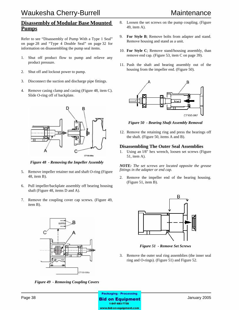
Disassembly of Modular Base Mounted PumpsRefer to see “Disassembly of Pump With a Type 1 Seal” on page 28 and “Type 4 Double Seal” on page 32 for information on disassembling the pump seal items.
1. Shut off product flow to pump and relieve any product pressure.
2. Shut off and lockout power to pump.
3. Disconnect the suction and discharge pipe fittings.
4. Remove casing clamp and casing (Figure 48, item C). Slide O-ring off of backplate.
5. Remove impeller retainer nut and shaft O-ring (Figure 48, item B).
6. Pull impeller/backplate assembly off bearing housing shaft (Figure 48, items D and A).
7. Remove the coupling cover cap screws. (Figure 49, item B).
8. Loosen the set screws on the pump coupling. (Figure 49, item A).
9. For Style B; Remove bolts from adapter and stand. Remove housing and stand as a unit.
10. For Style C; Remove stand/housing assembly, than remove end cap. (Figure 53, item C on page 39).
11. Push the shaft and bearing assembly out of the housing from the impeller end. (Figure 50).
12. Remove the retaining ring and press the bearings off the shaft. (Figure 50, items A and B).
Disassembling The Outer Seal Assemblies1. Using an l/8" hex wrench, loosen set screws (Figure
51, item A).
NOTE: The set screws are located opposite the grease fittings in the adapter or end cap.
2. Remove the impeller end of the bearing housing. (Figure 51, item B).
3. Remove the outer seal ring assemblies (the inner seal ring and O-rings). (Figure 51) and Figure 52.
Figure 48 - Removing the Impeller Assembly
Figure 49 - Removing Coupling Covers
Figure 50 - Bearing Shaft Assembly Removal
Figure 51 - Remove Set Screws
Page 38 95-03080 January 2005

Maintenance Waukesha Cherry-Burrell
Assembling the Outer Seal AssembliesReverse the above disassembly procedure with the added step of installing new O-rings in the seal rings.NOTE: Figure 52 shows seal position at motor end. Seals at pump end face inward. Make sure to tighten set screws when installing outer seal assemblies. (Figure 53).
NOTE: It is recommended that all rubber parts be replaced whenever a unit is dismantled for inspection or repair. Lubricate rubber parts with an approved/sanitary lubricant prior to assembly.
Pre-assembled (Cartridge) Seals
Pre-assembled (Cartridge) seals have all of the seal components mounted to a flange. They are pre-adjusted at the factory. Follow the seal manufacturer's (John Crane, A. W. Chesterton, etc.) recommendations regarding application, operation and maintenance.
NOTE: The cartridge seal comes with a set of removable lugs/spacers in place that are used to hold the assembly together until installation is final. Do not remove these lugs until installation is complete and you are told to do so in step 17 on page 42.
Disassembly of Pre-assembled (Cartridge) SealsThe following procedure covers the disassembly of pre-assembled (cartridge) seals.
1. Remove all flush connections and fittings.
2. Remove the casing clamp, casing and O-ring from the housing flange. (Figure 54).
3. Remove the impeller retainer nut and O-ring; then loosen the seal set screws. (Figure 55, item A).
.
Figure 52 - Seal Configuration
Figure 53 - Outer Seal Assemblies
Table 13: Call Outs for Figure 53
A. Outer Seal Assembly D. Set Screw
B. Set Screw E. Adaptor
C. End Cap F. Stand
Figure 54 - Remove Casing Clamp, Casing and O-ring
Figure 55 - Removal of Wet End
January 2005 95-03080 Page 39

Waukesha Cherry-Burrell Maintenance
4. Pull the impeller, backplate and seal off the bearingshaft as a unit. Set the assembly face down (on the impeller).
NOTE: The clearance shims that position the impeller within the casing are at the end of the impeller hub (inside the seal.) Keep shims together as a set for reassembly. (Figure 56).
5. Remove cap screws (Figure 56, item B) holding the cartridge seal to the seal adapter. (Figure 56, items C and E).
6. Remove seal unit from the backplate assembly.
7. Pull seal from seal adapter. (Figure 56, items C and E).
8. Remove seal adapter by removing socket head cap screws (Figure 56, item D) holding adapter to the back plate.
Assembly of a Pump With Pre-assembled (Cartridge) SealsThe following procedure covers the disassembly of pre-assembled (cartridge) seals.
1. Place shims, backplate and impeller on the shaft assembly. Hand tighten the impeller retainer bolt on the shaft.
2. Check impeller/backplate clearance with the backplate held firmly in position against motor adapter. Check the space between the back of the impeller and the backplate with a feeler gauge (.030 nominal) while holding the backplate tight against the bearing housing flange. (Any axial movement of the shaft should not be added to the .030 nominal clearance). (Figure 57). If needed, change this clearance by adding or removing shims. Shims (Figure 56, item A) are added on the drive shaft behind the impeller shaft (Figure 56, item G).
3. Confirm operating clearances by clamping the casing to the bearing housing flange and rotating the shaft/impeller manually to be sure the impeller does not touch the casing or backplate.
4. When proper shim pack is confirmed remove the casing, impeller and backplate leaving the shim pack on the shaft.
5. Insert L-gasket into the backplate. (Figure 58, items B and C).
Figure 56 - Remove Seal Assembly.
Table 14: Callouts For Figure 56
A. Shims E. Adaptor
B. Cap Screw F. Backplate
C. Cartridge Seal G. Impeller
D. Socket Head Screw
Figure 57 - Clearance Between Impeller and Backplate
Page 40 95-03080 January 2005

Maintenance Waukesha Cherry-Burrell
6. Insert cartridge adapter (Figure 58, item A) into thebackplate (Figure 58, item C) and tighten with four socket head cap screws.(Figure 58, item D).
7. Install the cartridge seal unit and use retaining bolts (Figure 59, item B) and flat washers (Figure 59, item A) to secure unit to the cartridge adapter. Make sure to not tighten the retaining bolts yet.
8. Apply FDA approved anti-seize compound to the shaft.
9. Install and position the seal guard. (Figure 60).
10. Slide the impeller, backplate and seal unit onto the shaft.
NOTE: Be sure the flushing ports in the cartridge seal are positioned with the inlet toward the bottom and the outlet toward the top. (Figure 62, item C).
11. Install the impeller key. (Figure 61, item A).
12. Install the O-ring on the impeller retainer bolt. (Figure 61, item C).
13. Install impeller retainer nut and tighten. (Figure 61,
item B).
14. Hold the backplate in place and tighten the cartridge seal into the cartridge adapter by tightening the cap screws (Figure 62, item E).
NOTE: The backplate and seal can be rotated to give access to the bolts through the holes in the guard.
Figure 58 - Insert L-gasket and Fasten Adapter in Place
Figure 59 - Fasten Seal Unit in Place
DANGER: Caution
Be sure the removable lugs/spacers that position the rotating part of the seal in the housing are in place at this time.
Figure 60 - Installing the Guard
Figure 61 - Installing Impeller Assembly
January 2005 95-03080 Page 41

Waukesha Cherry-Burrell Maintenance
15. Install O-ring and casing; clamp in place. (Figure 63).
16. Tighten the two set screws to the shaft. (Figure 62, item B).
17. Remove the lugs/spacers. (Figure 62, item A). NOTE: Keep lugs/spacers to reinstall on seal cartridge if removal is ever required.
18. Connect flushing fluid and flood seal.
19. Turn the shaft manually to be sure shaft rotates without the impeller hitting or binding.
Pedestal Base Mounted Pump Housing Lubrication
Waukesha Series S200 Pedestal Pumps are lubricated with GOA Micro-Plate 555 Lithium Complex Grease. Use only NLGI grade 2 Lithium Complex thickened greases to replenish bearing grease supply. Grease fittings indicated in Figure 64.
NOTE: Mixing greases that will not mix with the above products can change the viscosity/consistency of the grease resulting in bearing damage. If there is doubt remove the bearings, clean and re-pack.
For compatible lubricants contact Waukesha Application Engineering at
Telephone:
1-800-252-5200
Or 262-728-1900
Lubrication Schedule
NOTE: If operating temperatures are over 158°F. (70°C.) reduce hours by half for every 27°F.(15°C.) over the operating temperature.
Figure 62 - Typical Cartridge Seal
Table 15: Call Outs For Figure 62
A. Lugs/Spacers D. Seal Adaptor
B. Set Screw (2) E. Cap Screws
C. Flush Pots
Figure 63 - Install O-ring, Casing And Clamp
Figure 64 - Grease Fittings on the Pedestal Pump
Table 16: Lubrication Schedule
Size/RPM Hours
Small Bore/1750 RPM 4400
Small Bore/3500 RPM 2000
Large Bore/1750 RPM 2000
Large Bore/3500 RPM 1000
Page 42 95-03080 January 2005

Maintenance Waukesha Cherry-Burrell
Cartridge SealThe following pictorial list of cartridge seals is provided to assist in identifying some of the seals provided with the Model 200 centrifugal pumps. Use of these cartridges requires a cartridge seal adapter.
Figure 65 - Installed Cartridge Seal
Figure 66 - Typical Cartridge Seal Installation
Table 17: Call Outs for Figure 66
A. Socket Head Cap Screw
B. Cartridge Seal Assembly
C. Set Screw (2)
D. Cap Screw
E. Bearing Shaft
F. Clearance Shims
January 2005 95-03080 Page 43

Waukesha Cherry-Burrell Maintenance
Servicing the Electric MotorSee the motors manufacturer’s instructions for specific service information.
General Service InformationInspect units at regular intervals.
Keep units clean, and ventilation openings clear of dust, dirt or other debris.
Lubricate units per manufacturer’s instructions and instruction plate on Unit.
Motor Lubrication InstructionsSome small motors have sealed for life bearings which require no lubrication.
Greasable bearings are shipped with a high quality wide temperature range grease in the bearings.
Some motors can be greased. Refer to the motor manufacturer’s instructions for more information regarding lubrication procedures and additional service procedures.
DANGER: CAution
Do not over grease. Excessive lubrication may damage the unit.
DANGER: warning
Disconnect all power sources to the unit and discharge all parts which may retain an electrical charge before attempting any maintenance or repair. Screens and covers must be maintained in place when unit is in operation.
Page 44 95-03080 January 2005

Waukesha Cherry-Burrell Parts Lists
Parts Lists
Seal Kits
Basic Seal Kit - Type 1 Seal - Sanitary Pump Model
Complete Seal Kit - Type 1 Seal - Sanitary Pump Model
*Includes LV and HV models
KIT CONTAINS QTYMODEL
S2045 S2065* S2085* S2092
CARBON SEAL (FKM & EPDM) 1 9-225A 9-225A 9-225A 9-225A
SEAL O-RING (FKM) 1 V70224 V70224 V70224 V70224
SEAL O-RING (EPDM) 1 E70224 E70224 E70224 E70224
CASING O-RING (FKM) 1 V70252 V70439 V70446 V70450
CASING O-RING (EPDM) 1 E70252 E70439 E70446 E70450
IMPELLER O-RING (FKM) 1 V70214 V70220 V70220 V70220
IMPELLER O-RING (EPDM) 1 E70214 E70220 E70220 E70220
KIT ORDER # (FKM) 309-241 309-242 309-243 309-244
KIT ORDER # (EPDM) 309-241E 309-242E 309-243E 309-244E
KIT CONTAINS QTYMODEL
S2045 S2065* S2085* S2092
CARBON SEAL (FKM & EPDM) 1 9-225A 9-225A 9-225A 9-225A
SEAL O-RING (FKM) 1 V70224 V70224 9 10V V70224
SEAL O-RING (EPDM) 1 E70224 E70224 E70224 E70224
CASING O-RING (FKM) 1 V70252 V70439 V70446 V70450
CASING O-RING (EPDM) 1 E70252 E70439 E70446 E70450
IMPELLER O-RING (FKM) 1 V70214 V70220 V70220 V70220
IMPELLER O-RING (EPDM) 1 E70214 E70220 E70220 E70220
STATIONARY SEAL (FKM & EPDM) 1 23-17 23-17 23-17 23-17
L - GASKET (FKM & EPDM) 1 9-37 9-37 9-37 9-37
KIT ORDER # (FKM) 309-245 309-246 309-247 309-248
KIT ORDER # (EPDM) 309-245E 309-246E 309-247E 309-248E
Issued Date: January 2005 95-03080 Page 45 Revision Date: June 2005

Parts Lists Waukesha Cherry-Burrell
Basic Seal Kit - Type 4 Seal - Sanitary Pump Model
Complete Seal Kit - Type 4 Seal - Sanitary Pump Model
*Includes LV and HV models
KIT CONTAINS QTYMODEL
S2045 S2065* S2075 S2085* S2092
CARBON SEAL (FKM & EPDM) 2 9-225A 9-225A 9-225A 9-225A 9-225A
SEAL O-RING (FKM) 2 V70224 V70224 V70224 V70224 V70224
SEAL O-RING (EPDM) 2 E70224 E70224 E70224 E70224 E70224
CASING O-RING (FKM) 1 V70252 V70439 V70446 V70446 V70450
CASING O-RING (EPDM) 1 E70252 E70439 E70446 E70446 E70450
IMPELLER O-RING (FKM) 1 V70214 V70220 V70220 V70220 V70220
IMPELLER O-RING (EPDM) 1 E70214 E70220 E70220 E70220 E70220
HOUSING O-RING (FKM) 2 V70039 V70039 V70039 V70039 V70039
HOUSING O-RING (EPDM) 2 E70039 E70039 E70039 E70039 E70039
KIT ORDER # (FKM) 309-249 309-250 309-251 309-251 309-252
KIT ORDER # (EPDM) 309-249E 309-250E 309-251E 309-251E 309-252E
KIT CONTAINS QTYMODEL
S2045 S2065* S2075 S2085* S2092
CARBON SEAL (FKM & EPDM) 2 9-225A 9-225A 9-225A 9-225A 9-225A
SEAL O-RING (FKM) 2 V70224 V70224 V70224 V70224 V70224
SEAL O-RING (EPDM) 2 E70224 E70224 E70224 E70224 E70224
CASING O-RING (FKM) 1 V70252 V70439 V70446 V70446 V70450
CASING O-RING (EPDM) 1 E70252 E70439 E70446 E70446 E70450
IMPELLER O-RING (FKM) 1 V70214 V70220 V70220 V70220 V70220
IMPELLER O-RING (EPDM) 1 E70214 E70220 E70220 E70220 E70220
HOUSING O-RING (FKM) 2 V70039 V70039 V70039 V70039 V70039
HOUSING O-RING (EPDM) 2 E70039 E70039 E70039 E70039 E70039
STATIONARY SEAL (FKM & EPDM) 2 23-17 23-17 23-17 23-17 23-17
L - GASKET (FKM & EPDM) 2 9-37 9-37 9-37 9-37 9-37
KIT ORDER # (FKM) 309-253 309-254 309-255 309-255 309-256
KIT ORDER # (EPDM) 309-253E 309-254E 309-255E 309-255E 309-256E
Page 46 95-03080 Issued Date: January 2005 Revision Date: June 2005

Waukesha Cherry-Burrell Parts Lists
Class VI Elastomer Kits
**Class VI Elastomers are only sold as kits**
Motor Shaft Shims
MODELSINGLE DOUBLE
FKM EPDM FKM EPDM
S2045 118023 118069 118028 118074
S2065 118024 118070 118029 118075
S2075 118025 118071 118030 118076
S2085 118025 118071 118030 118076
S2092 118026 118072 118031 118077
Table 18: Motor Shaft Shim
MOTOR SHAFT SHIM PART # MOTOR NEMA FRAME SIZE QTY
.005" THK. 35-4 254JM-326JM AS REQUIRED
.010" THK. 35-5 254JM-326JM AS REQUIRED
.020" THK. 35-6 254JM-326JM AS REQUIRED
.005" THK. 35-1 143JM-215JM AS REQUIRED
.010" THK. 35-2 143JM-215JM AS REQUIRED
.020" THK. 35-3 143JM-215JM AS REQUIRED
Issued Date: January 2005 95-03080 Page 47 Revision Date: June 2005

Parts Lists Waukesha Cherry-Burrell
Seal Components All Pumps
Page 48 95-03080 Issued Date: January 2005 Revision Date: June 2005

Waukesha Cherry-Burrell Parts Lists
Seal Components All Pumps
ITEM # PART # TYPE 1/1C SEAL QTY
TYPE 4 SEAL QTY
1 Deflector 69-1 1 -Stationary Seal Purbide (1.75") 23-17 1 2
Silicone Carbide (1.75") 23-17A 1 2Ceramic (1.75") 23-17E 1 2
Tungsten Carbide (1.75") 23-17F 1 23 Seal Retainer 23-78 1 -4 1/4 -20 x 1/2" Bolt (4 each) 30-62 4 -
Rotary Seal Carbon (1.75") 9-225A 1 2Purbide (1.75") 9-225B 1 2
Silicone Carbide (1.75") 9-225C 1 2Tungsten Carbide (1.75") 9-225F 1 2
* 6 1/4-20 x 3/8" Set Screw (2 each) 30-178 2 1* 7 Spring Retainer (1.75") 23-77 1 -
L-gasket FKM (1.75") 9-37 1 2EPDM (1.75") 9-37E 1 2FFKM (1.75") 9-37K 1 2
Silicone 9-37R 1 2O-ring FKM (1.75") V70224 1 2
EPDM (1.75") E70224 1 2Chemrez® (1.75") C75224 1 2
FFKM (1.75") K75224 1 2Silicone (1.75") S75224 1 2
* 10 Washer, tabbed 43-87 1 2* 11 Spring 24-65 3 6* 12 O-ring, housing V70039 2
13 Housing, seal 23-80 114 Retainer, seat 23-79 115 1/4-20 x 3" Cap Screw 30-175 4 416 Slinger, 142-215JM 69-4 - 117 1/4" N.P.T. Plug 78-155 - 118 Block, water cascade 134-2 119 8-32 x 1/4" Socket Head 30-176 220 1/4" Plastic Hose 74-1 9"21 1/4" Hose Fitting 78-18 1
CT100-185
9*
* 8
DESCRIPTION
2
*
*
5
Issued Date: January 2005 95-03080 Page 49 Revision Date: June 2005

Parts Lists Waukesha Cherry-Burrell
S2045 Components (Close Coupled)
ITEM # 20RA 15RA 15RA EP 20RA EPS2045 1515 Solid Bar Casing S-Line CENTPT00501 CENTPT00015 CENTPT00014 CENTPT00016
Buttweld CENTPT00502 CENTPT00018 CENTPT00017 CENTPT00019150# Flange CENTPT00503 CENTPT00021 CENTPT00020 CENTPT00022
DIN CENTPT00504 CENTPT00024 CENTPT00023 CENTPT00025S2045 2015 Solid Bar Casing S-Line CENTPT00501 CENTPT00027 CENTPT00026 CENTPT00028
Buttweld CENTPT00502 CENTPT00030 CENTPT00029 CENTPT00031150# Flange CENTPT00503 CENTPT00033 CENTPT00032 CENTPT00034
DIN CENTPT00504 CENTPT00036 CENTPT00035 CENTPT000372 S2045 Impellers Small Bore CENTPT00702 CENTPT00703 CENTPT00704 CENTPT00447
S2045 (129-773X) Retainer NutSmall Bore (142/184) CENTPT00705 CENTPT00706 CENTPT00707 CENTPT00708
10 Backplate CENTPT00709 CENTPT00710 CENTPT00711 CENTPT00441CT100-186a
DESCRIPTION
1
3
Page 50 95-03080 Issued Date: January 2005 Revision Date: June 2005

Waukesha Cherry-Burrell Parts Lists
S2045 Components (Close Coupled)
*Recommended spare parts. See “Seal Components All Pumps” on page 48 for metric seal kits.
ITEM # PART # QTY
O-ring FKM V70214 1EPDM E70214 1FFKM T80214 1
5 Adapter, motor 2-235 16 Seal guard (Type 1 Seal) 70-27 17 3/8-16 x 3/4" Hex screw 30-30X 48 3/8" Lock washer 43-28 4
O-ring FKM V70252 1EPDM E70252 1
Silicone S75252 1PTFE Encapsulated T80252 1
FFKM K75252 111 Casing clamp 119-71 112 Key 3/16" 184-215JM Motor Frame 65-3 1
CT100-186
*
*
DESCRIPTION
9
4
Issued Date: January 2005 95-03080 Page 51 Revision Date: June 2005

Parts Lists Waukesha Cherry-Burrell
S2065/S2065LV/S2065HV Components (Close Coupled)
ITEM # 20RA 15RA 15RA EP 20RA EPS2065LV 1515 Solid Bar Cas ing S-Line CENTPT00483 CENTPT00039 CENTPT00038 CENTPT00040
Buttweld CENTPT00509 CENTPT00042 CENTPT00041 CENTPT00043150# Flange CENTPT00510 CENTPT00045 CENTPT00044 CENTPT00046
DIN CENTPT00511 CENTPT00048 CENTPT00047 CENTPT00049S2065LV 2015 Solid Bar Cas ing S-Line CENTPT00269 CENTPT00051 CENTPT00050 CENTPT00052
Buttweld CENTPT00512 CENTPT00054 CENTPT00053 CENTPT00055150# Flange CENTPT00513 CENTPT00057 CENTPT00056 CENTPT00058
DIN CENTPT00514 CENTPT00060 CENTPT00059 CENTPT00061S2065LV 2515 Solid Bar Cas ing S-Line CENTPT00515 CENTPT00063 CENTPT00062 CENTPT00064
Buttweld CENTPT00516 CENTPT00066 CENTPT00065 CENTPT00067150# Flange CENTPT00517 CENTPT00069 CENTPT00068 CENTPT00070
DIN CENTPT00518 CENTPT00072 CENTPT00071 CENTPT00073S2065 2520 Solid Bar Cas ing S-Line CENTPT00519 CENTPT00075 CENTPT00074 CENTPT00076
Buttweld CENTPT00520 CENTPT00078 CENTPT00077 CENTPT00079150# Flange CENTPT00521 CENTPT00081 CENTPT00080 CENTPT00082
DIN CENTPT00522 CENTPT00084 CENTPT00083 CENTPT00085S2065HV 3020 Solid Bar Cas ing S-Line CENTPT00787 CENTPT00805 CENTPT00809 CENTPT00813
Buttweld CENTPT00790 CENTPT00806 CENTPT00810 CENTPT00814150# Flange CENTPT00792 CENTPT00807 CENTPT00811 CENTPT00815
DIN CENTPT00788 CENTPT00808 CENTPT00812 CENTPT00816S2065LV Im pellers Sm all Bore CENTPT00393 CENTPT00304 CENTPT00299 CENTPT00403
Large Bore CENTPT00712 CENTPT00713 CENTPT00714 CENTPT00715S2065 Im pellers Sm all Bore CENTPT00262 CENTPT00716 CENTPT00717 CENTPT00333
Large Bore CENTPT00718 CENTPT00719 CENTPT00720 CENTPT00334S2065HV Im pellers Sm all Bore CENTPT00796 CENTPT00798 CENTPT00800 CENTPT00803
Large Bore CENTPT00797 CENTPT00799 CENTPT00801 CENTPT00804Standard (129-771X) Retainer Nut
Sm all Bore (143/215) CENTPT00538 CENTPT00539 CENTPT00540 CENTPT00541Standard (129-772X) Retainer Nut
Large Bore (324/365TC, 254/326JM) CENTPT00543 CENTPT00544 CENTPT00542 CENTPT0045110 S2065LV/S2065/S2065HV Backplate CENTPT00317 CENTPT00738 CENTPT00308 CENTPT00434
CT10 0 -18 7a
DESCRIPTION
3
1
2
Page 52 95-03080 Issued Date: January 2005 Revision Date: June 2005
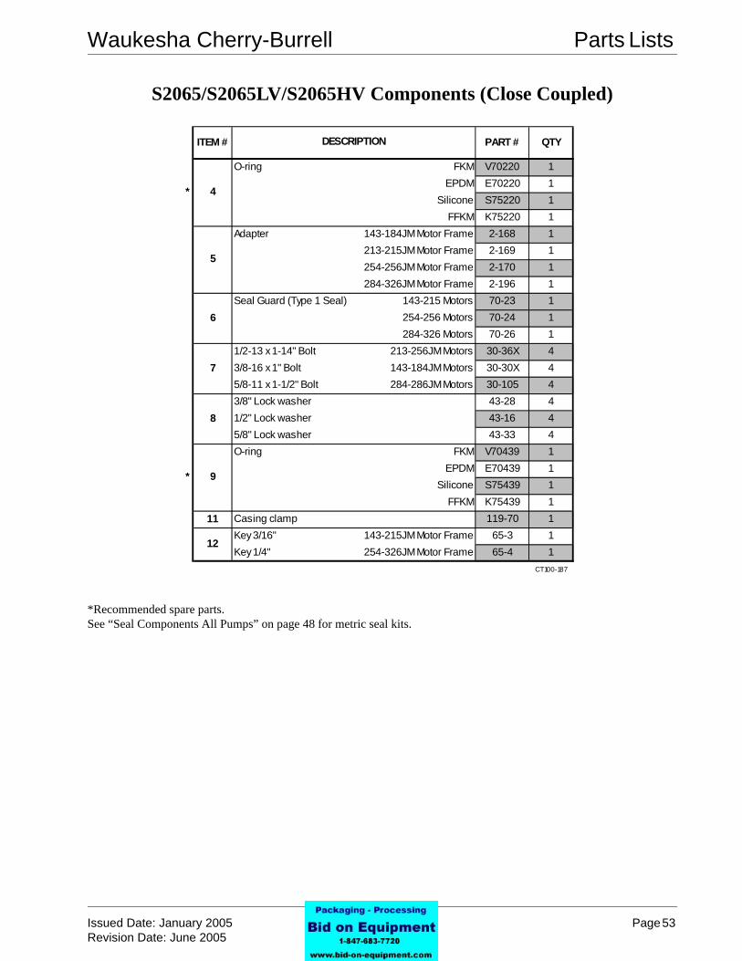
Waukesha Cherry-Burrell Parts Lists
S2065/S2065LV/S2065HV Components (Close Coupled)
*Recommended spare parts. See “Seal Components All Pumps” on page 48 for metric seal kits.
ITEM # PART # QTY
O-ring FKM V70220 1EPDM E70220 1
Silicone S75220 1FFKM K75220 1
Adapter 143-184JM Motor Frame 2-168 1213-215JM Motor Frame 2-169 1254-256JM Motor Frame 2-170 1284-326JM Motor Frame 2-196 1
Seal Guard (Type 1 Seal) 143-215 Motors 70-23 1254-256 Motors 70-24 1284-326 Motors 70-26 1
1/2-13 x 1-14" Bolt 213-256JM Motors 30-36X 43/8-16 x 1" Bolt 143-184JM Motors 30-30X 45/8-11 x 1-1/2" Bolt 284-286JM Motors 30-105 43/8" Lock washer 43-28 41/2" Lock washer 43-16 45/8" Lock washer 43-33 4O-ring FKM V70439 1
EPDM E70439 1Silicone S75439 1
FFKM K75439 111 Casing clamp 119-70 1
Key 3/16" 143-215JM Motor Frame 65-3 1Key 1/4" 254-326JM Motor Frame 65-4 1
CT100-187
* 9
12
7
8
*
5
6
DESCRIPTION
4
Issued Date: January 2005 95-03080 Page 53 Revision Date: June 2005

Parts Lists Waukesha Cherry-Burrell
S2075 Components (Close Coupled)
ITEM # 20RA 15RA 15RA EP 20RA EPS2075 3015 Solid Bar Casing S-Line CENTPT00487 CENTPT00486 CENTPT00485 CENTPT00488
Buttweld CENTPT00687 CENTPT00688 CENTPT00689 CENTPT00690150# Flange CENTPT00691 CENTPT00692 CENTPT00693 CENTPT00694
DIN CENTPT00695 CENTPT00696 CENTPT00697 CENTPT00698S2075 Impellers Small Bore CENTPT00499 CENTPT00495 CENTPT00493 CENTPT00497
Large Bore CENTPT00500 CENTPT00496 CENTPT00494 CENTPT00498S2075 (129-771X) Retainer Nut Small Bore CENTPT00538 CENTPT00539 CENTPT00540 CENTPT00541S2075 (129-772X) Retainer Nut Large Bore CENTPT00543 CENTPT00544 CENTPT00542 CENTPT00451
10 Backplate CENTPT00492 CENTPT00490 CENTPT00489 CENTPT00491CT100-192
DESCRIPTION
2
3
1
Page 54 95-03080 Issued Date: January 2005 Revision Date: June 2005

Waukesha Cherry-Burrell Parts Lists
S2075 Components (Close Coupled)
*Recommended spare parts.See “Seal Components All Pumps” on page 57 for metric seal kits.
ITEM # PART # QTY
O-ring FKM V70220 1EPDM E70220 1
Silicone S75220 1FFKM K75220 1
Adapter 143-184JM Motor Frame 2-171 1213-215JM Motor Frame 2-172 1254-256JM Motor Frame 2-173 1
284JM and Larger Motor Frame 2-174 1Seal Guard 143-215JM Motors 70-23 1
254-256 JM Motors 70-24 1284-324JM Motors 70-26 1
284JM and Larger Motors 114508 13/8-16 x 1" Bolt 143-184JM Motors 30-30 41/2-13 x 1 1/4" Bolt 213-256JM Motors 30-36X 45/8-11 x 1-1/2" Bolt 284JM and Larger Motors 30-105 43/8" Lock washer 43-28 41/2" Lock washer 43-16 45/8" Lock washer 43-33 4O-ring FKM V70373 1
EPDM E70373 1Silicone S75373 1
FFKM K75373 111 Casing clamp 119-69 1
Key 3/16" 143-215JM Frame Motors 65-3 1Key 1/4" 254-326JM Frame Motors 65-4 1
CT100-188
DESCRIPTION
4
5
12
*
*
8
9
6
7
Issued Date: January 2005 95-03080 Page 55 Revision Date: June 2005

Parts Lists Waukesha Cherry-Burrell
S2085/2085LV Components (Close Coupled)
ITEM # 20RA 15RA 15RA EP 20RA EPS2085LV 2015 Solid Bar Casing S-Line CENTPT00300 CENTPT00087 CENTPT00086 CENTPT00088
Buttweld CENTPT00523 CENTPT00090 CENTPT00089 CENTPT00091150# Flange CENTPT00524 CENTPT00093 CENTPT00092 CENTPT00094
DIN CENTPT00525 CENTPT00096 CENTPT00095 CENTPT00097S2085 3025 Solid Bar Casing S-Line CENTPT00526 CENTPT00099 CENTPT00098 CENTPT00100
Buttweld CENTPT00527 CENTPT00102 CENTPT00101 CENTPT00103150# Flange CENTPT00528 CENTPT00105 CENTPT00104 CENTPT00106
DIN CENTPT00529 CENTPT00108 CENTPT00107 CENTPT00109S2085 4025 Solid Bar Casing S-Line CENTPT00530 CENTPT00111 CENTPT00110 CENTPT00112
Buttweld CENTPT00531 CENTPT00114 CENTPT00113 CENTPT00115150# Flange CENTPT00532 CENTPT00117 CENTPT00116 CENTPT00118
DIN CENTPT00533 CENTPT00120 CENTPT00119 CENTPT00121S2085LV Impellers Small Bore CENTPT00728 CENTPT00306 CENTPT00302 CENTPT00729
Large Bore CENTPT00730 CENTPT00731 CENTPT00732 CENTPT00733S2085 Impellers Small Bore CENTPT00721 CENTPT00722 CENTPT00723 CENTPT00724
Large Bore CENTPT00725 CENTPT00726 CENTPT00727 CENTPT00448Standard (129-771X) Retainer Nut
Small Bore (143/215) CENTPT00538 CENTPT00539 CENTPT00540 CENTPT00541Standard (129-772X) Retainer Nut
Large Bore (324/365TC, 254/326JM) CENTPT00543 CENTPT00544 CENTPT00542 CENTPT0045110 S2085LV/S2085 Backplate CENTPT00739 CENTPT00740 CENTPT00741 CENTPT00430
CT100-188a
DESCRIPTION
3
1
2
Page 56 95-03080 Issued Date: January 2005 Revision Date: June 2005

Waukesha Cherry-Burrell Parts Lists
S2085/2085LV Components (Close Coupled)
*Recommended spare parts. See “Seal Components All Pumps” on page 48 for metric seal kits.
ITEM # PART # QTY
O-ring FKM V70220 1EPDM E70220 1
Silicone S75220 1FFKM K75220 1
Adapter 143-184JM Motor Frame 2-171 1213-215JM Motor Frame 2-172 1254-256JM Motor Frame 2-173 1
284JM and Larger Motor Frame 2-174 1Seal Guard 143-215JM Motors 70-23 1
254-256 JM Motors 70-24 1284-324JM Motors 70-26 1
284JM and Larger Motors 114508 13/8-16 x 1" Bolt 143-184JM Motors 30-30 41/2-13 x 1 1/4" Bolt 213-256JM Motors 30-36X 45/8-11 x 1-1/2" Bolt 284JM and Larger Motors 30-105 43/8" Lock washer 43-28 41/2" Lock washer 43-16 45/8" Lock washer 43-33 4O-ring FKM V70373 1
EPDM E70373 1Silicone S75373 1
FFKM K75373 111 Casing clamp 119-69 1
Key 3/16" 143-215JM Frame Motors 65-3 1Key 1/4" 254-326JM Frame Motors 65-4 1
CT100-188
*
*
8
9
6
7
DESCRIPTION
4
5
12
Issued Date: January 2005 95-03080 Page 57 Revision Date: June 2005

Parts Lists Waukesha Cherry-Burrell
S2092 Components (Close Coupled)
ITEM # 20RA 15RA 15RA EP 20RA EPS2092 3020 Solid Bar Casing S-Line CENTPT00534 CENTPT00123 CENTPT00122 CENTPT00124
Buttweld CENTPT00535 CENTPT00126 CENTPT00125 CENTPT00127150# Flange CENTPT00536 CENTPT00129 CENTPT00128 CENTPT00130
DIN CENTPT00537 CENTPT00132 CENTPT00131 CENTPT00133S2092 Impellers Small Bore CENTPT00734 CENTPT00735 CENTPT00736 CENTPT00737
Large Bore CENTPT00353 CENTPT00699 CENTPT00700 CENTPT00701Standard (129-771X) Retainer Nut (Kit) CENTPT00538 CENTPT00539 CENTPT00540 CENTPT00541
Small Bore (143/215)Standard (129-772X) Retainer Nut (Kit) CENTPT00543 CENTPT00544 CENTPT00542 CENTPT00451
Large Bore (324/365TC, 254/326JM)10 S2092 Backplate CENTPT00742 CENTPT00743 CENTPT00744 CENTPT00745
DESCRIPTION
3
1
2
Page 58 95-03080 Issued Date: January 2005 Revision Date: June 2005

Waukesha Cherry-Burrell Parts Lists
S2092 Components (Close Coupled)
*Recommended spare parts. See “Seal Components All Pumps” on page 48 for metric seal kits.
ITEM # PART # QTY
O-ring FKM V70220 1EPDM E70220 1
Silicone S75220 1FFKM K75220 1
Adapter 143-184JM Motor Frame 2-171 1213-215JM Motor Frame 2-172 1254-256JM Motor Frame 2-173 1
284JM and Larger Motor Frame 2-174 1Seal Guard 143-215JM Motors 70-23 1
254-256 JM Motors 70-24 1284-324JM Motors 70-26 1
284JM and Larger Motors 114508 13/8-16 x 1" Bolt 143-184JM Motors 30-30 41/2-13 x 1 1/4" Bolt 213-256JM Motors 30-36X 45/8-11 x 1-1/2" Bolt 284JM and Larger Motors 30-105 43/8" Lock washer 43-28 41/2" Lock washer 43-16 45/8" Lock washer 43-33 4O-ring FKM V70373 1
EPDM E70373 1Silicone S75373 1
FFKM K75373 111 Casing clamp 119-69 1
Key 3/16" 143-215JM Frame Motors 65-3 1Key 1/4" 254-326JM Frame Motors 65-4 1
CT100-188
*
*
8
9
6
7
DESCRIPTION
4
5
12
Issued Date: January 2005 95-03080 Page 59 Revision Date: June 2005

Parts Lists Waukesha Cherry-Burrell
Motor Mounts
Leg Kits
143-145JM 110256
182-184JM 110255
213-215JM 110254
254-256JM 110253
284-286JM 110252
324-326JM 110251
Page 60 95-03080 Issued Date: January 2005 Revision Date: June 2005

Waukesha Cherry-Burrell Parts Lists
Pedestal Mounted Pumps Small Bore
Issued Date: January 2005 95-03080 Page 61 Revision Date: June 2005

Parts Lists Waukesha Cherry-Burrell
ITEM # STYLE MOTOR PART #Bearing housing S2045 B,C ALL 68-6
S2065 B,C ALL 68-7S2075-S2085-S2092 B,C ALL 68-8
2 Shaft B,C ALL 62-528X3 Bearing 6309 B,C ALL 23-101
* 4 Bearing 6209 B,C ALL 23-100* 5 Retaining ring B,C ALL 43-139
6 Seal outer B,C ALL 23-907 Seal inner B,C ALL 23-89
* 9 031 O-ring inner B,C ALL N7003111 HHCS 1/2-13 x 2" ALL ALL 30-138X13 SHSS 1/4-20 x 3/8" B,C ALL 30-17814 Grease fitting B,C ALL BD009200015 Stand B,C ALL 4-3416 HHCS 1/2-13 x 1" B,C ALL 30-78X
* 17 041 O-ring outer B,C ALL N70041Cover seal S2065-S2092 B,C ALL 70-33
S2045 B,C ALL 70-3219 Cover coupling B ALL 70-3123 HHCS 1/4-20 x 1/2" LG. B,C ALL 30-62
CT100-189
18
DESCRIPTION
1
Page 62 95-03080 Issued Date: January 2005 Revision Date: June 2005

Waukesha Cherry-Burrell Parts Lists
ITEM # STYLE MOTOR PART #Adapter 56C B 56C 2-247
56C B 143TC 2-24756C B 145TC 2-247
182TC B 182TC 2-248182TC B 184TC 2-248182TC B 213TC 2-248182TC B 215TC 2-248182TC B 254TC 2-248182TC B 256TC 2-248
Spacer adapter 213TC B 213TC 43-134213TC B 215TC 43-134254TC B 254TC 43-135254TC B 256TC 43-135
Coupling half .625 W B,C 56 11-37.875 5S B,C 143 11-101.875 5S B,C 145 11-101
1.125 5S B,C 182 11-1021.125 5S B,C 184 11-1021.375 6S B,C 213-215 332201.625 7S B,C 254-256 33227
Coupling sleeve 4J B,C 56 11-295JE B,C 143/184 11-306JE B,C 213/215 11-317JE B,C 254/256 11-32
Coupling half 1.0 4J B,C 56 11-951.0 5S B,C 143/184 11-941.0 6S B,C 213/215 332171.0 7S B,C 254/256 33222
HHCS 3/8-16 x 1" B 56/145 30-30X1/2-13 x 1" B 182/184 30-78X
1/2-13 x 1-3/4" B 213/215 30-127X1/2-13 x 2-1/2" B 254/256 30-87X
32 HHCS 1/2-13 x 1-1/2" B,C ALL 30-10333 Washer 1/2" B,C ALL 43-23334 Lock washer 1/2" B,C ALL 43-1635 SHCS 1/4-20 x 1-1/2" B,C ALL 30-222X36 Adapter, cartridge seal B,C ALL 23-91X37 HHCS 1/2-13 x 1-3/4" B,C ALL 30-127X38 Flat washer 1/2" B,C ALL 43-31X
L-gasket FKM B,C ALL 9-37EPDM B,C ALL 9-37EFFKM B,C ALL 9-37K
CT100-189a
*
*
24
DESCRIPTION
25
39
28
27
30
29
Issued Date: January 2005 95-03080 Page 63 Revision Date: June 2005

Parts Lists Waukesha Cherry-Burrell
Pedestal Mounted Pumps Large Bore
Page 64 95-03080 Issued Date: January 2005 Revision Date: June 2005

Waukesha Cherry-Burrell Parts Lists
ITEM # STYLE MOTOR PART #Bearing housing S2065 B,C ALL 68-9
S2075-S2085-S2092 B,C ALL 68-102 Shaft B,C ALL 62-539X
* 3 Bearing 5311 B,C ALL 23-98* 5 Retaining ring B,C ALL 43-138
6 Seal outer B,C ALL 23-957 Seal inner motor end B,C ALL 23-948 Seal inner motor impeller end B,C ALL 23-93
* 9 035 O-ring inner B,C ALL N70035* 10 033 O-ring inner impeller B,C ALL N70033
11 HHCS 1/2-13 x 3-1/4" ALL ALL 30-221X13 SHSS 1/4-20 x 3/8" B,C ALL 30-17814 Grease fitting B,C ALL BD009200015 Stand B,C ALL 4-3516 HHCS 1/2-13 x 1-1/4" B,C ALL 30-36X
* 17 045 O-ring outer B,C ALL N7004518 Seal Guard S2065-S2085 B,C ALL 70-3319 Cover coupling adapter B ALL 70-3420 Cover coupling L.H. C ALL 70-3521 Cover coupling R.H. C ALL 70-3622 Brace, cover coupling C ALL 2-25223 HHCS 1/4-20 x 1/2" LG. B,C ALL 30-62
CT100-190
DESCRIPTION
1
Issued Date: January 2005 95-03080 Page 65 Revision Date: June 2005

Parts Lists Waukesha Cherry-Burrell
ITEM # STYLE MOTOR PART #Adapter B 213TC 2-249
B 215TC 2-249B 254TC 2-249B 256TC 2-249B 284TC 2-250B 286TC 2-250B 324TC 2-250B 326TC 2-250B 364TC 2-250B 365TC 2-250
Spacer adapter B 254TC 43-134B 256TC 43-134B 324TC 43-136B 326TC 43-136
B,C 364TC 43-137B,C 365TC 43-137
26 End cap housing LB C ALL 23-97Coupling half 1.375 6S B,C 213-215 33220
1.625 7S B,C 254-256 332271.875 7S B,C 284 332291.875 7S B,C 286 332292.125 8S B,C 324-326 332372.375 8S B,C 364 11-1072.375 8S B,C 365 11-107
Coupling sleeve 6JES B,C 213/215 11-317JES B,C 254/286 11-328JES B,C 324/326 11-338HSS B,C 364/365 33189
Coupling half 1.250 6S B,C 213/215 332191.250 7S B,C 254/286 332241.250 8S B,C 324/365 33230
HHCS 1/2-13 x 1-1/4" B 213/215 30-36X1/2-13 x 1-1/4" B 324/365 30-21
32 HHCS 1/2-13 x 1-1/2" B,C ALL 30-103X33 Washer 1/2" B,C ALL 43-31X34 Lock washer 1/2" B,C ALL 43-1635 SHCS 1/4-20 x 1-1/2" B,C ALL 30-222X36 Adapter, cartridge seal B,C ALL 23-91X37 HHCS 1/2-13 x 1-3/4" B,C ALL 30-127X38 Flat washer 1/2" B,C ALL 43-31X
L-gasket FKM B,C ALL 9-37EPDM B,C ALL 9-37EFFKM B,C ALL 9-37K
CT100-190a
39*
*
30
28
29
24
27
25
DESCRIPTION
Page 66 95-03080 Issued Date: January 2005 Revision Date: June 2005

Waukesha Cherry-Burrell Troubleshooting
TroubleshootingPROBLEM POSSIBLE CAUSE SUGGESTED ACTION
Not Enough Liquid Delivered Pump not primed. Prime pump. Install a priming system if possible.
Suction or discharge plugged or closed.
Open suction. If plugged shutdown pump and remove blockage.
Air leak in supply or at seal area. Check system for air leaks and repair as necessary. Replace seals if required.
Wrong direction of rotation. Adjust motor electrical wiring to correct rotation.
Discharge head too high. Lower discharge head requirement.
Suction lift too high. Lower pump in system until the pump is easily supplied with material.
Speed too slow (low voltage, wrong frequency, wrong motor).
Adjust voltage and frequency. Change motor if necessary.
Excessive air in material. Adjust system to remove excess air from material before it reaches the pump.
Insufficient NPSH (Net Positive Suction Head) available.
Adjust system to provide correct NPSH.
Impeller diameter too small for duty.
Contact your Waukesha Cherry-Burrell customer service representative for sizing information. WCB Customer ServiceTelephone: 1-800-252-5200Or 262-728-1900
Not Enough Pressure Air leak in supply or at seal area. Check system for air leaks and repair as necessary. Replace seals if required.
Wrong direction of rotation. Adjust motor electrical wiring to correct rotation.
Speed too slow (low voltage, wrong frequency, wrong motor).
Adjust voltage and frequency. Change motor if necessary.
Excessive air in material. Adjust system to remove excess air from material before it reaches the pump.
Impeller diameter too small for duty.
Contact your Waukesha Cherry-Burrell customer service representative for sizing information. WCB Customer ServiceTelephone: 1-800-252-5200Or 262-728-1900
Motor Overload Faulty electrical connections. Check wiring and repair/replace as necessary.
January 2005 95-03080 Page 67

Troubleshooting Waukesha Cherry-Burrell
Unrestricted discharge resulting in too high a flow rate.Add discharge restriction to lower flow rate.
Impeller interference. Disassemble pump and inspect for damage. Remove interference if still present. Replace worn/damaged parts.
Seal binding. Disassemble pump and inspect for damage. Check for material crystallization on seals.
Discharge head too low allowing pump to deliver too much liquid.
Raise discharge head until pump achieves proper resistance to flow.
Liquid heavier or more viscous than rating.
Contact your Waukesha Cherry-Burrell customer service representative for sizing information. WCB Customer ServiceTelephone: 1-800-252-5200Or 262-728-1900
Overload heaters too small for motor.
Inspect and replace as necessary.
Electrical supply, voltage, frequency, incorrect.
Adjust voltage and frequency. Change motor if necessary.
Impeller diameter too large for duty.
Contact your Waukesha Cherry-Burrell customer service representative for sizing information. WCB Customer ServiceTelephone: 1-800-252-5200Or 262-728-1900
Defective motor. Replace motor.
Vibration/Noise Pump not level. Make sure all legs are touching the floor. Level pump.
Piping not supported. Support all piping as described in the installation section.
Starved suction/Supply line blocked.
Shutdown pump and remove blockage.
Foreign material in pump. Disassemble pump, remove all foreign material and inspect for damage. Replace worn/damaged parts.
Starved suction/Insufficient NPSH (Net Positive Suction Head) available.
Adjust system to provide correct NPSH.
Impeller hub/impeller shaft worn.
Disassemble pump and inspect for damage. Replace worn parts.
Impeller shaft loose or bent. Disassemble pump and inspect for damage.
Page 68 95-03080 January 2005

Waukesha Cherry-Burrell Troubleshooting
Impeller out of balance. Disassemble pump and inspect fordamage. Replace impeller.
Motor bearings worn. Disassemble motor and inspect for damage. Replace worn parts.
Starved suction/supply line too long.
Shorten system supply line.
Starved suction/supply line too small.
Install larger supply lines.
Excessive air in material. Adjust system to remove excess air from material before it reaches the pump.
Rapid Seal Wear Incorrect impeller shaft location; excessive spring loading.
Adjust pump alignment to motor and piping.
Water Hammer. Adjust system to reduce air in system and sudden starts or stops in flow.
Impeller shaft loose or bent. Disassemble pump and inspect for damage. Replace worn/damaged parts.
Abrasive product. Contact your Waukesha Cherry-Burrell customer service representative for sizing information. WCB Customer ServiceTelephone: 1-800-252-5200Or 262-728-1900
Prolonged “dry” running. Adjust process to insure pump has a continual fresh supply of product during operation.
Abrasive solids (unfiltered) in flush water supplied to seal.
Use only filtered water in seal flush system.
Seal Leaks Gasket damaged or worn. Disassemble pump and inspect for damage.
Seal not installed correctly. Disassemble pump and inspect seal for damage (replace if necessary). Install seal correctly and assemble pump.
Carbon seal worn or damaged. Disassemble pump and inspect seal for damage (replace if necessary).
Inlet/Outlet connection loose or no gasket.
Inspect Inlet/outlet connection for gasket and tighten connection.
Casing clamp loose. Tighten clamp.
January 2005 95-03080 Page 69